problem sheet 3 the per unit system and per unit analysis ...50726f626c656d... · college of...
TRANSCRIPT
College of Engineering_ Department of Electrical
Engineering,
Fall 2011-2012
Problem sheet 3
The per unit system and per unit analysis of simple power systems
1. Express in per-unit values the following voltages with respect to a voltage base of 400kV. (i) 420kV, (ii) 395kV, (iii) 405kV
(Ans: (i) 1.05 p.u. (ii) 0.9875 p.u. (iii) 1.0125 p.u.)
2. Using a base of 100MVA, express the following apparent power flows in per-unit form. (i) 692MVA, (ii) 1000MVA
(Ans: (i) 6.92 p.u. (ii) 10 p.u.)
3. A transmission line is represented by a series impedance Z=6+j80. Express this impedance in per-unit form using base values of 132kV (line voltage) and 10MVA (three-phase power).
(Ans : Zpu = 3.44x10⁻³ +j45.9x10-3 p.u.)
4. A transmission line has a total per-phase impedance of (4+j60) and total shunt admittance of j2x10-3 S. Using the nominal line voltage (345kV) and the three-phase apparent power (100MVA) as base values, determine the per-unit impedance and per-unit admittance of the line.
(Ans: Zpu = 3.36x10⁻³ +j50.4x10-3 p.u. , Ypu = j2.38 p.u.)
5. Re-calculate the per-unit values in Q4 using new base values of 350kV and 150MVA. (Ans: Zpu = 4.89x10⁻³ +j73.45x10-3 p.u. , Ypu = j1.63 p.u.)
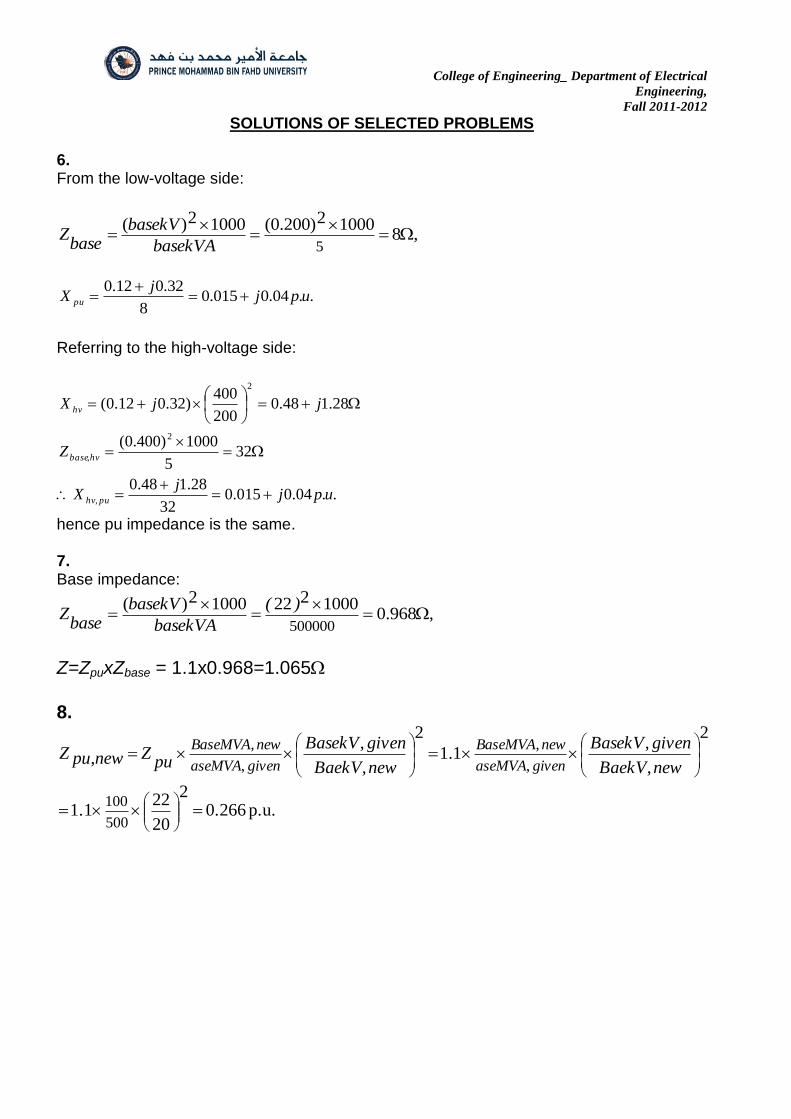
6. Show that the per-unit impedance of a single-phase, two-winding transformer calculated using rated primary voltage and primary referred impedances is the same as that calculated using rated secondary voltage and secondary referred impedances. Calculate the per-unit impedance of a 5kVA, 200/400V 50Hz transformer having an equivalent
series impedance of (0.12+j0.32)referred to the primary (low-voltage) side, using first the primary referred values and then the secondary referred values. Take the rated value of voltage as the voltage base.
7. A generator (which may be represented by an emf in series with an inductive reactance) is rated 500MVA, 22kV. Its Y-connected windings have a reactance of 1.1 p.u. . Find the ohmic value of the reactance of the windings.
(Ans: 1.065)
8. The generator of Problem 7 is in a circuit for which the bases are specified as 100MVA and 20KV. Starting with the per unit value given in Problem 7, find the per unit value of the reactance of the generator windings on the specified base.
(Ans:0.182 p.u.)
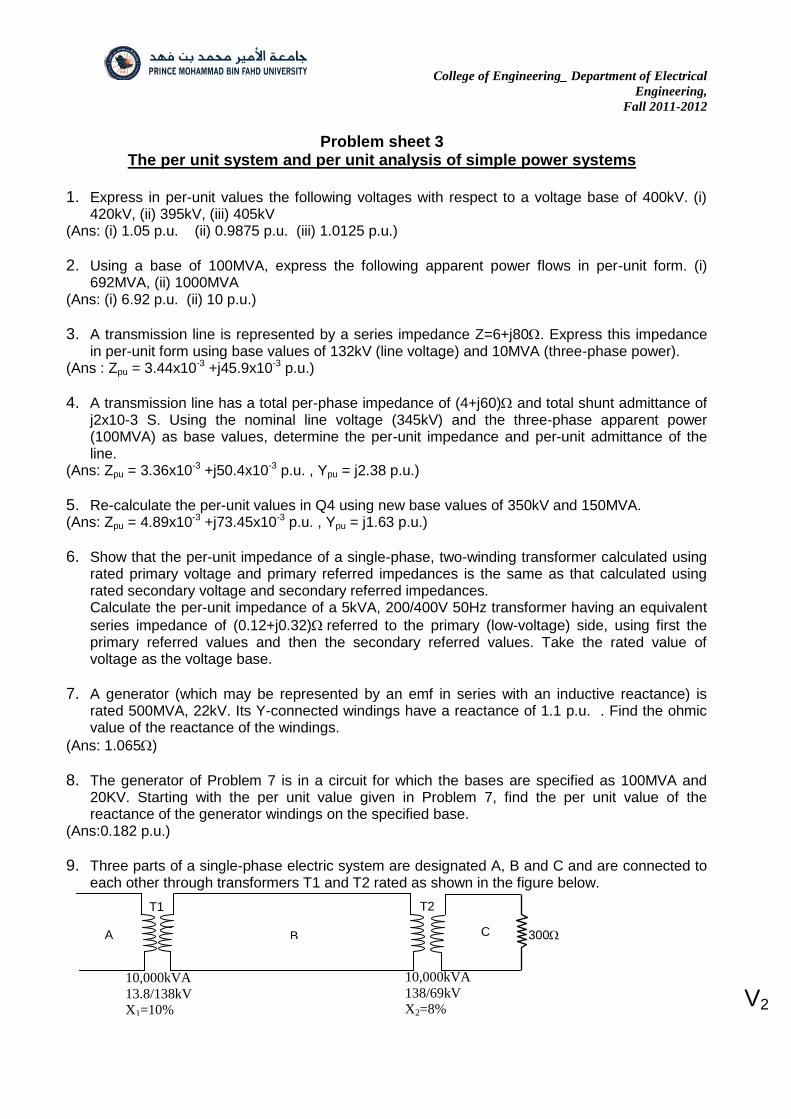
9. Three parts of a single-phase electric system are designated A, B and C and are connected to each other through transformers T1 and T2 rated as shown in the figure below.
A B C 300
T1 T2
10,000kVA
13.8/138kV
X1=10%
10,000kVA
138/69kV
X2=8% V2
College of Engineering_ Department of Electrical
Engineering,
Fall 2011-2012
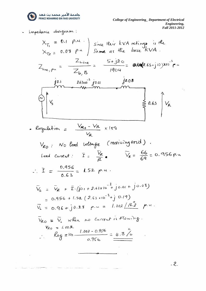
Between T1 and T2 is a line of impedance 5+j20 300 resistive load is connected to circuit C. If the base in circuit B is chosen as 10,000 KVA, 138KV, find the per unit value of the resistive load referred to circuits C, B and A. Draw an impedance diagram neglecting magnetising current and transformer resistances. Determine the voltage regulation if the voltage at the load is 66KV with the assumption that the voltage input to circuit A remains constant. (Ans: 0.63 p.u. the same for the three circuits. Per unit impedances to show in series in the impedance diagram: XT1=j0.1 p.u, Zline=0.01+j0.042 p.u., XT2=j0.08 p.u. and ZLoad=0.63 p.u. , reg=100x(Vo-V)/V=7.6%)
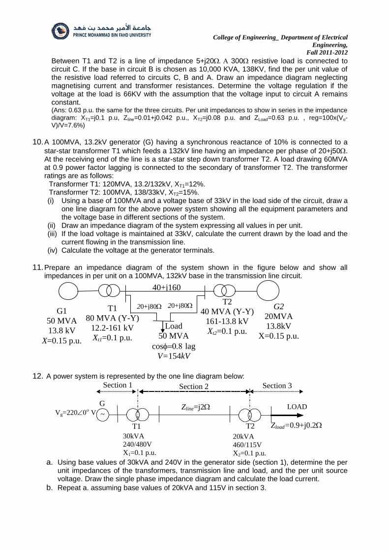
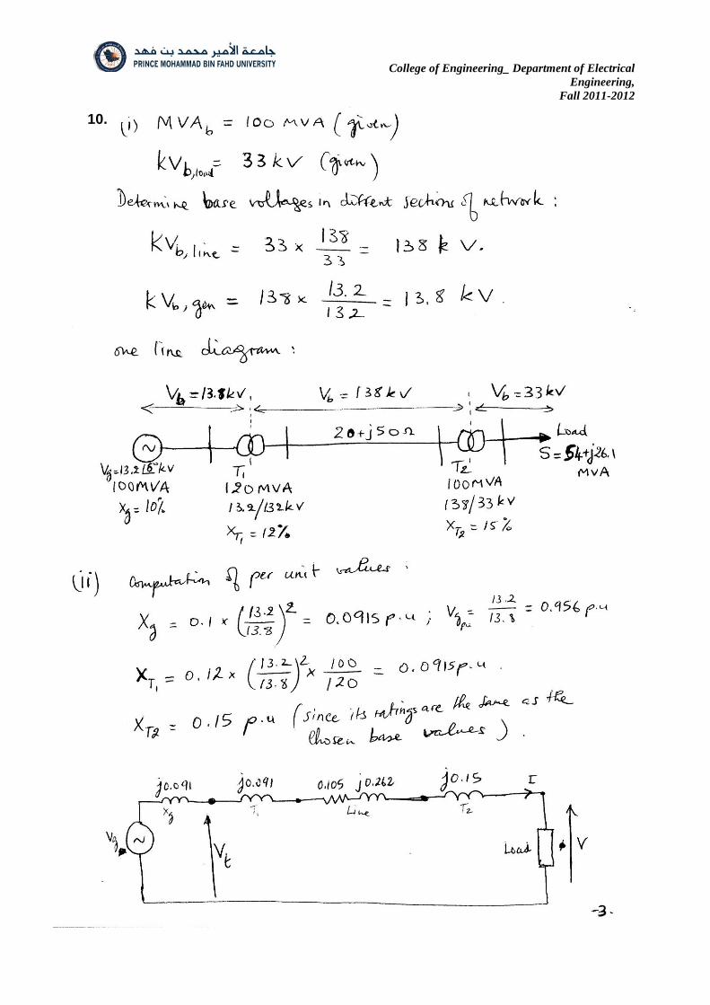
10. A 100MVA, 13.2kV generator (G) having a synchronous reactance of 10% is connected to a
star-star transformer T1 which feeds a 132kV line having an impedance per phase of 20+j50. At the receiving end of the line is a star-star step down transformer T2. A load drawing 60MVA at 0.9 power factor lagging is connected to the secondary of transformer T2. The transformer ratings are as follows:
Transformer T1: 120MVA, 13.2/132kV, XT1=12%. Transformer T2: 100MVA, 138/33kV, XT2=15%. (i) Using a base of 100MVA and a voltage base of 33kV in the load side of the circuit, draw a
one line diagram for the above power system showing all the equipment parameters and the voltage base in different sections of the system.
(ii) Draw an impedance diagram of the system expressing all values in per unit. (iii) If the load voltage is maintained at 33kV, calculate the current drawn by the load and the
current flowing in the transmission line. (iv) Calculate the voltage at the generator terminals.
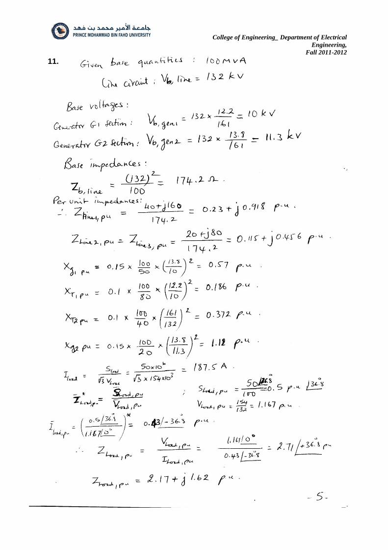
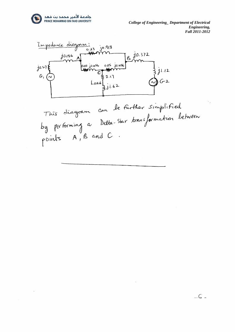
11. Prepare an impedance diagram of the system shown in the figure below and show all impedances in per unit on a 100MVA, 132kV base in the transmission line circuit.
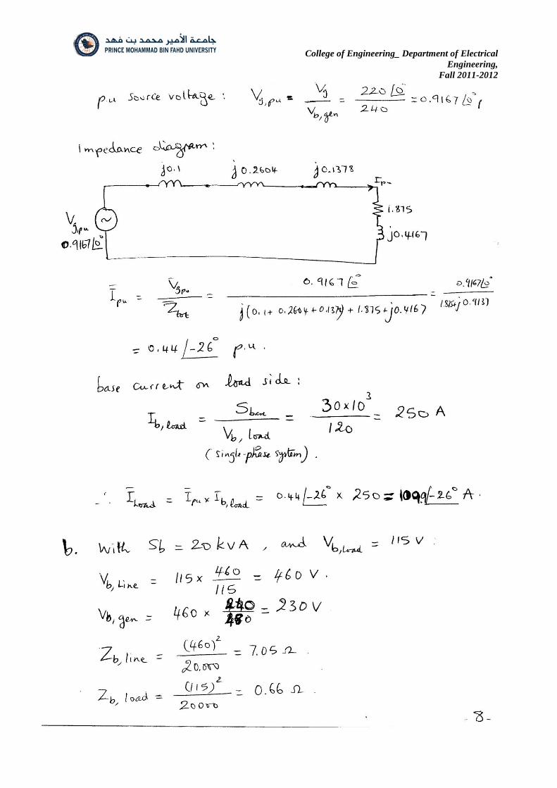
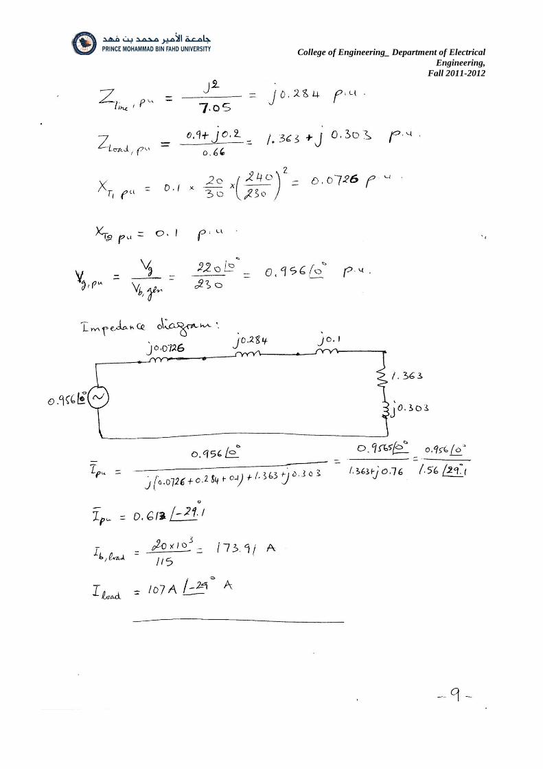
12. A power system is represented by the one line diagram below:
a. Using base values of 30kVA and 240V in the generator side (section 1), determine the per
unit impedances of the transformers, transmission line and load, and the per unit source voltage. Draw the single phase impedance diagram and calculate the load current.
b. Repeat a. assuming base values of 20kVA and 115V in section 3.
G
T1
T2
Zline=j2 Vg=220
V
LOAD
Zload=0.9+j0.2
30kVA
240/480V
X1=0.1 p.u.
Section 1 Section 2 Section 3
20kVA
460/115V
X2=0.1 p.u.
~
20+j80 20+j80 T1
80 MVA (Y-Y)
12.2-161 kV
Xt1=0.1 p.u.
T2
40 MVA (Y-Y)
161-13.8 kV
Xt2=0.1 p.u.
G2
20MVA
13.8kV
X=0.15 p.u.
40+j160
G1
50 MVA
13.8 kV
X=0.15 p.u.
Load
50 MVA
cos lag
V=154kV
College of Engineering_ Department of Electrical
Engineering,
Fall 2011-2012
SOLUTIONS OF SELECTED PROBLEMS
6. From the low-voltage side:
,810002)200.0(10002)(
5
basekVA
basekVbase
Z
..04.0015.08
32.012.0upj
jX pu
Referring to the high-voltage side:
..04.0015.032
28.148.0
325
1000)400.0(
28.148.0200
400)32.012.0(
,
2
,
2
upjj
X
Z
jjX
puhv
hvbase
hv
hence pu impedance is the same. 7. Base impedance:
,968.0100022210002)(
500000
)(
basekVA
basekVbase
Z
Z=ZpuxZbase = 1.1x0.968=1.065
8.
p.u. 0.2662
20
221.1
2
,
,1.1
2
,
,,
500
100
,
,
,
,
newBaekV
givenBasekV
newBaekV
givenBasekVpu
ZnewpuZgivenaseMVA
newBaseMVA
givenaseMVA
newBaseMVA

College of Engineering_ Department of Electrical
Engineering,
Fall 2011-2012
9.
College of Engineering_ Department of Electrical
Engineering,
Fall 2011-2012
College of Engineering_ Department of Electrical
Engineering,
Fall 2011-2012
10.

College of Engineering_ Department of Electrical
Engineering,
Fall 2011-2012
College of Engineering_ Department of Electrical
Engineering,
Fall 2011-2012
11.
College of Engineering_ Department of Electrical
Engineering,
Fall 2011-2012

College of Engineering_ Department of Electrical
Engineering,
Fall 2011-2012
12.
College of Engineering_ Department of Electrical
Engineering,
Fall 2011-2012
College of Engineering_ Department of Electrical
Engineering,
Fall 2011-2012