problem sfilename: problem set 1.pdfet 1
DESCRIPTION
Filename: Problem Set 1.pdfTRANSCRIPT

NTNU
Norwegian University of Science and Technology
TKT 4198
Structural Design – Advanced Course
Problem Set 1
Delivery Deadline: Sunday 20/09/2015
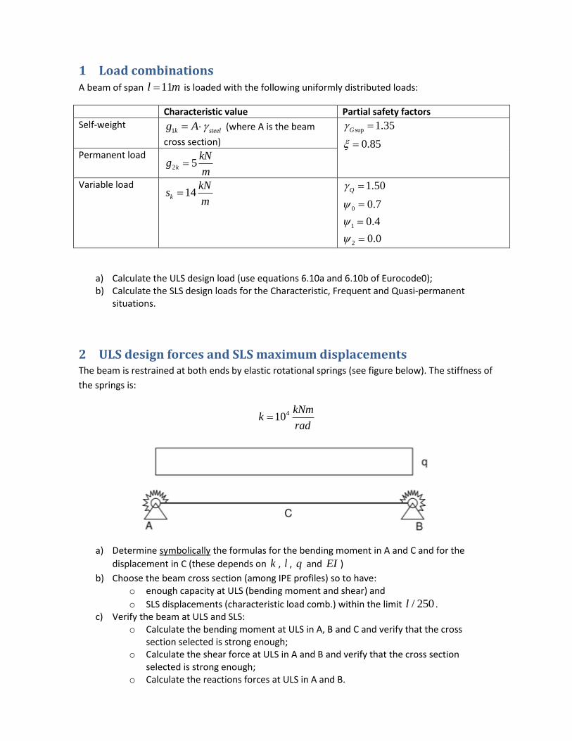
1 Load combinations A beam of span 11l m is loaded with the following uniformly distributed loads:
Characteristic value Partial safety factors
Self-weight 1k steelg A (where A is the beam
cross section)
sup 1.35
0.85
G
Permanent load 2 5k
kNg
m
Variable load 14k
kNs
m
0
1
2
1.50
0.7
0.4
0.0
Q
a) Calculate the ULS design load (use equations 6.10a and 6.10b of Eurocode0); b) Calculate the SLS design loads for the Characteristic, Frequent and Quasi-permanent
situations.
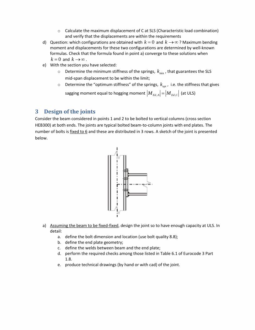
2 ULS design forces and SLS maximum displacements The beam is restrained at both ends by elastic rotational springs (see figure below). The stiffness of
the springs is:
410kNm
krad
a) Determine symbolically the formulas for the bending moment in A and C and for the
displacement in C (these depends on k , l , q and EI )
b) Choose the beam cross section (among IPE profiles) so to have: o enough capacity at ULS (bending moment and shear) and
o SLS displacements (characteristic load comb.) within the limit / 250l . c) Verify the beam at ULS and SLS:
o Calculate the bending moment at ULS in A, B and C and verify that the cross section selected is strong enough;
o Calculate the shear force at ULS in A and B and verify that the cross section selected is strong enough;
o Calculate the reactions forces at ULS in A and B.
o Calculate the maximum displacement of C at SLS (Characteristic load combination) and verify that the displacements are within the requirements
d) Question: which configurations are obtained with 0k and k ? Maximum bending moment and displacements for these two configurations are determined by well-known formulas. Check that the formula found in point a) converge to these solutions when
0k and k . e) With the section you have selected:
o Determine the minimum stiffness of the springs, mink , that guarantees the SLS
mid-span displacement to be within the limit;
o Determine the “optimum stiffness” of the springs, optk , i.e. the stiffness that gives
sagging moment equal to hogging moment , ,Ed A Ed CM M (at ULS)
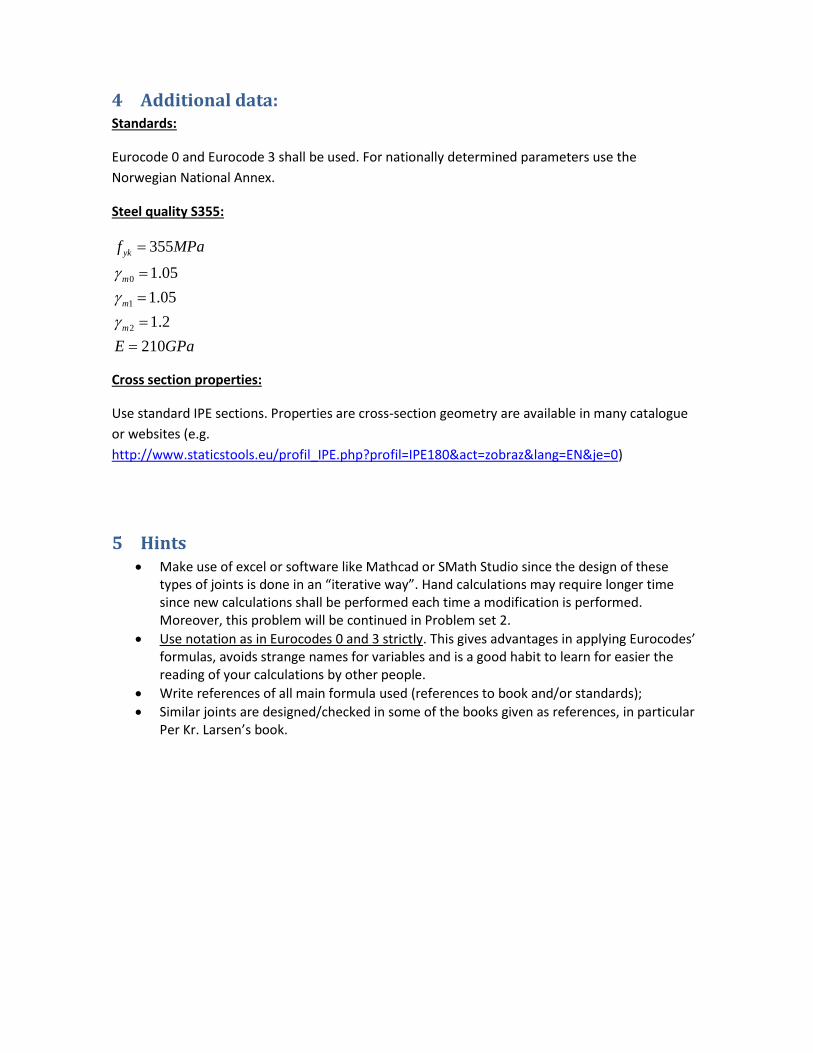
3 Design of the joints Consider the beam considered in points 1 and 2 to be bolted to vertical columns (cross section
HEB300) at both ends. The joints are typical bolted beam-to-column joints with end plates. The
number of bolts is fixed to 6 and these are distributed in 3 rows. A sketch of the joint is presented
below.
a) Assuming the beam to be fixed-fixed, design the joint so to have enough capacity at ULS. In detail:
a. define the bolt dimension and location (use bolt quality 8.8); b. define the end plate geometry; c. define the welds between beam and the end plate; d. perform the required checks among those listed in Table 6.1 of Eurocode 3 Part
1.8. e. produce technical drawings (by hand or with cad) of the joint.
4 Additional data: Standards:
Eurocode 0 and Eurocode 3 shall be used. For nationally determined parameters use the
Norwegian National Annex.
Steel quality S355:
0
1
2
355
1.05
1.05
1.2
210
yk
m
m
m
f MPa
E GPa
Cross section properties:
Use standard IPE sections. Properties are cross-section geometry are available in many catalogue
or websites (e.g.
http://www.staticstools.eu/profil_IPE.php?profil=IPE180&act=zobraz&lang=EN&je=0)
5 Hints Make use of excel or software like Mathcad or SMath Studio since the design of these
types of joints is done in an “iterative way”. Hand calculations may require longer time since new calculations shall be performed each time a modification is performed. Moreover, this problem will be continued in Problem set 2.
Use notation as in Eurocodes 0 and 3 strictly. This gives advantages in applying Eurocodes’ formulas, avoids strange names for variables and is a good habit to learn for easier the reading of your calculations by other people.
Write references of all main formula used (references to book and/or standards);
Similar joints are designed/checked in some of the books given as references, in particular Per Kr. Larsen’s book.