problem set 5: solutions - university of...
TRANSCRIPT

UNIVERSITY OF ALABAMADepartment of Physics and Astronomy
PH 126 / LeClair Fall 2009
Problem Set 5: Solutions
1. A Helmholtz coil consists of two identical circular coils of radius R separated by a distance equal to their radii,as shown at below. Each carries current I in the same direction. (a) Find the field at any point along the coil axisbetween the two coils. (b) Show that ∂B/∂z vanishes at the midpoint. (c) Show that ∂2B/∂z2 also vanishes at themidpoint of the two coils.
I I
z
We first want to find the field at an arbitrary point z somewhere between the two coils, then find dB/dz andevaluate it at the midpoint. We don’t just want the field at the midpoint; we need its spatial variation to find thederivative(s) and only then do we evaluate our quantities at the midpoint between the two coils.
Let z = 0 at the intersection of the plane of the bottom coil and the z axis. The field from the bottom coil at anarbitrary point a distance z along the axis due to the bottom coil is that of a single current loop centered on theorigin, which we have already established:
B =µoI
2R2
(z2 + R2)3/2(single loop)
At a position z, since the separation of the coils is R, we are a distance R − z from the upper coil. We need onlyreplace z with R−z in the expression above to find the field from the upper coil at a distance z < R from the bottomcoil. Since the currents are in the same directions for both coils, the magnetic fields are in the same direction, andwe may just add them together:
Btot = Blower + Bupper =µoI
2R2
(z2 + R2)3/2+
µoI
2R2[
(R − z)2
+ R2]3/2
Now we only need calculate dB/dz:

∂Btot
∂t=
µoIR2
2
d
dz
1
(z2 + R2)3/2+
d
dz
1((R − z)
2+ R2
)3/2
=
µoIR2
2
− 32
(2z)
(z2 + R2)5/2+
− 32
(2z − 2R)((R − z)
2+ R2
)5/2
=
µoIR2
2
−3z
(z2 + R2)5/2+
3R − 3z((R − z)
2+ R2
)5/2
Evaluating this at point P, where z=R/2,
∂Btot
∂t
∣∣∣∣∣z= R
2
=µoIR2
2
−3R2(
R2
4 + R2)5/2
+3R − 3R
2((R − R
2
)2+ R2
)5/2
=
µoIR2
2
[−3R
2(
5R2
4
)5/2+
3R
2(
5R2
4
)5/2
]= 0
Indeed, the derivative of the field with respect to position is zero, implying high uniformity near the center of theHelmholtz arrangement. Repeat to find the second spatial derivative:
∂2Btot
∂z2=
µoIR2
2
−3
(z2 + R2)5/2+
−3z(− 5
2
)(2z)
(z2 + R2)7/2+
3((R − z)
2+ R2
)5/2+
3 (z − R)(− 5
2
)(2z − 2R)(
(R − z)2
+ R2)7/2
=
µoIR2
2
15z2
(z2 + R2)7/2−
3
(z2 + R2)5/2−
15 (z − R)2((R − z)
2+ R2
)7/2+
3((R − z)
2+ R2
)5/2
Evaluating at z=R/2,
∂2Btot
∂z2
∣∣∣∣∣z= R
2
=µoIR2
2
15(
R2
4
)((
R2
4
)+ R2
)7/2−
3((R2
4
)+ R2
)5/2−
15(
R2
4
)((
R2
4
)+ R2
)7/2+
3((R2
4
)+ R2
)5/2
= 0
One can also show that d3B/dz3 is zero as well (but it is messy), meaning the field is extremely uniform over areasonably large volume between the two coils.
Incidentally, the field midway between the two coils, with z=R/2 is B=8µoI/53/2R, about 1.4 times the field onewould get directly at the center of a single coil. Not only is the field more uniform, it is larger. How convenient!
2. A current loop of radius R lies in the xy plane carrying a steady current I. Show that for distances large comparedto R the resulting magnetic field may be written

Br =µ0|~µ | cos θ
2πr3(1)
Bθ =µ0|~µ | sin θ
4πr3(2)
Here r is the distance from the center of the loop, and θ is relative to the z axis (which is perpendicular to the planeof the loop).
See the figure below. Let the loop lie in the xy plane, and let the vector ~r point from the source point to thefield point P . We will restrict ourselves field points in the yz plane (i.e., x=0). Since the problem is rotationallysymmetric about the z axis, this is sufficient to find the field everywhere.At the source point, a segment of the current loop d~l is located at (x,y, z)=(R cos ϕ,R sinϕ, 0) and ϕ runs from0 to 2π. Let the vector ~r p point from the origin, at the center of the current loop, to the field point P lying at(0,y, z).
P (0,y,z)
dl
r
R
dφdl
R
φ’
rP
yx
θ
I
z
We can, in principle, find the magnetic field at an arbitrary point with the Biot-Savart law using the distance ~r froma current element d~l to the source point P
~B =µoI
4π
∫d~l′ × ~r
|~r |3(3)
However, we have a bit of geometry to overcome before this is of any use. First, it is useful define an vector ~R
which lies in the xy plane and points from the origin to the element d~l . This is nothing more than the radial vectorin cylindrical coordinates, and it is easy to construct given the location of d~l :
~R = R cos ϕ x + R sinϕ y (4)
Actually, from a certain point of view we’ll be mixing cylindrical and spherical coordinates freely, which mightbe disconcerting. From another point of view it is irrelevant so long as we are careful to put everything back intocartesian coordinates before attempting any vector products. Anyway: the element d~l is just the arclength definedby R and dϕ, which is also easily defined in terms of the angular unit vector ϕ and its cartesian equivalent.
d~l′ = R dϕ ϕ = −R sinϕ dϕ x + R cos ϕ dϕ y (5)

A bit more tricky in this case is to find the vector ~r . Given a vector locating the field point ~r p and ~R , the relativeposition vector is
~r = ~r p − ~R = −R cos ϕ x + (y − R sinϕ) y + z z (6)
You can verify this in one of two ways. First, since we have ~R in component form above, one can just subtractit from ~r p which is the standard radial vector in spherical coordinates. Second, from the geometry of the figureabove, you can find the components along the x, y, and z axis with a bit of trigonometry. Either way, the result isthe same. The magnitude of the separation vector is thus
|~r |2 = R2 cos2 ϕ + y2 − 2yR sinϕ + R2 sin2 ϕ + z2 = R2 + y2 + z2 − 2Ry sinϕ (7)
Next, we can calculate the cross product d~l × ~r and simplify it a bit:
d~l′ × ~r =
∣∣∣∣∣∣∣x y z
−R sinϕ dϕ R cos ϕ dϕ 0−R cos ϕ (y − R sinϕ) z
∣∣∣∣∣∣∣ (8)
= Rz cos ϕ dϕ x + Rz sinϕ dϕ y +(−Ry sinϕ dϕ + R2 dϕ
)z (9)
= R dϕ [z cos ϕ x + z sinϕ y + (R − y sinϕ) z] (10)
That’s it: all we have to do next is set up the integral. This is where the “fun” starts of course. And by “fun” wemean “pain” as usual. The integral itself is over all the d~l making up the current loop, which in this case means anintegral over dϕ from 0 to 2π. Just plugging everything into the Biot-Savart law, we have
~B =µoI
4π
2π∫0
R dϕ [z cos ϕ x + z sinϕ y + (R − y sinϕ) z]
[R2 + y2 + z2 − 2Ry sinϕ]3/2(11)
Right off the bat, we can show that the x component vanishes, since it is a pure differential:i
Bx =µoIRz
4π
2π∫0
cos ϕ dϕ
(R2 + y2 + z2 − 2Ry sinϕ)3/2=
µoIz
4πy
1√R2 + y2 + z2 − 2Ry sinϕ
∣∣∣∣∣2π
0
= 0 (12)
This simplifies things a bit:
~B =µoI
4π
2π∫0
R dϕ [z sinϕ y + (R − y sinϕ) z]
[R2 + y2 + z2 − 2Ry sinϕ]3/2(13)
Of course, we have one more nagging point: we actually want the r and θ components of the field, not the y and z
components. No matter: first, just remember that since we have restricted the field point to the yz plane (so x=0)iConsider a change of variable u=R2 + y2 + z2 − 2yR sinϕ if you don’t see this right away.

Br = By sin θ + Bz cos θ (14)
Bθ = By cos θ − Bz sin θ (15)
r = sin θ y + cos θ z (16)
θ = cos θ y − sin θ z (17)
r2 = y2 + z2 (18)
Using these relationships and Eq. 13, we can find the radial component without too much trouble. That is, if weremember that z sin θ=y cos θ, r2 =y2 + z2, and y=r sin θ . . .
Br =µoI
4π
2π∫0
R dϕ [z sinϕ sin θ + R cos θ − y sinϕ cos θ]
[R2 + y2 + z2 − 2Ry sinϕ]3/2=
µoI
4π
2π∫0
R dϕ [sinϕ (z sin θ − y cos θ) + R cos θ]
[R2 + r2 − 2rR sin θ sinϕ]3/2
Br =µoIR2 cos θ
4π
2π∫0
dϕ
[R2 + r2 − 2rR sin θ sinϕ]3/2(19)
The angular component is not much more work, if we this time note that z cos θ + y sin θ=z2/r + y2/r=r
Bθ =µoI
4π
2π∫0
R dϕ [z sinϕ cos θ − R sin θ + y sinϕ sin θ]
[R2 + r2 − 2rR sin θ sinϕ]3/2=
µoIR
4π
2π∫0
dϕ sinϕ (z cos θ + y sin θ) − dϕ sin θ
[R2 + r2 − 2rR sin θ sinϕ]3/2
Bθ =µoIR
4π
2π∫0
dϕ (r sinϕ − R sin θ)
[R2 + r2 − 2rR sin θ sinϕ]3/2(20)
At this point, extreme displeasure sets in. It is not that our expressions for Br and Bθ seem unsightly: that muchwe could live with. What is more hideous, on closer inspection, is that both components involve elliptical integrals,which have no analytic solution. This is useless to us, so we will need an approximation. The most sensible thing isto consider large distances from the loop, such that r�R. This will simplify the nasty denominator in the integral,which is the real source of our trouble. Considering points for which R/r�1,
1
[R2 + r2 − 2rR sin θ sinϕ]3/2=
1r3
1[1 +
R2
r2−
2R
rsinϕ sin θ
]3/2≈ 1
r3
[1 −
3R2
2r2+
3R
rsinϕ sin θ
](21)
This approximation gives an analytically solvable integral for Br:
Br ≈µoIR2 cos θ
4π
2π∫0
dϕ
r3
[1 −
3R2
2r2+
3R
rsinϕ sin θ
]=
µoIR2 cos θ
4πr3
[ϕ
(1 −
3R2
2r2
)−
3R
rcos ϕ sin θ
]2π
0
Br ≈µoIR2 cos θ
4πr3(2π)
(1 −
3R2
2r2
)(22)
In the limit that R/r�1, we may safely neglect terms which are second order in R/r. If we recognize the magnetic

moment of the loop |~µ |=πR2I, we are halfway home:
Br ≈µo|~µ | cos θ
2πr3(r� R) (23)
We can just use the same approximation for the radial component, this time with the benefit of hindsight: thesecond-order term in R/r can be neglected, and any terms involving only sinϕ will integrate to zero over [0, 2π]
Bθ ≈µoIR
4πr3
2π∫0
(r sinϕ − R sin θ)
[1 −
3R2
2r2+
3R
rsinϕ sin θ
]dϕ
Bθ ≈µoIR
4πr3
2π∫0
r sinϕ
[1 −
3R2
2r2
]+ 3R sin2 ϕ sin θ − R sin θ
(1 −
3R2
r2
)−
3R2
2rsinϕ sin2 θ dϕ
Bθ ≈µoIR
4πr3
2π∫0
r sinϕ
[1 −
3R2
2r2−
3R2
2r2sin2 θ
]+ 3R sin2 ϕ sin θ − R sin θ
(1 −
3R2
r2
)dϕ
Bθ ≈µoIR
4πr3
[32R sin θ (ϕ − sinϕ cos ϕ) − Rϕ sinϕ
]2π
0
=µoIR
4πr3[3πR sin θ − 2πR sin θ]
Bθ ≈µo|~µ | sin θ
4πr3(r� R) (24)
In total, we may write the field as
~B =µo|~µ |
4πr3
(2 cos θ r + sin θ θ
)(25)
3. Find the magnetic field at point P due to the current distribution shown below. Hint: Break the loop into seg-ments, and use superposition.
I
I
I I
y
xP
a
b
The easiest way to do solve this is by superposition. Since the magnetic field obeys superposition, we can considerour odd current loop above to be the same as two semicircles plus two small straight segments. We know that themagnetic field at the center of a circular loop of radius r carrying a current I is

B =µoI
2r(loop radius r)
If you did not remember this, it is easily derived from the Biot-Savart law . . . or you could notice that problem 5actually gives you this expression if you set z = 0. As a quick reminder, for a circle of radius r, our infinitesimallength element dl is just rdθ. For a current circulating around the ring in the θ direction, a vector length elementpointing along the current direction is then d~l =rdθ θ. We can now apply the Biot-Savart law:
d~B =µoI
4π
d~l × r
r2=
µoI
4π
rdθ θ× r
r2=
µoI
4πrdθ z
~B =
∫circle
d~B =
2π∫0
µoI
4πrdθ z =
µoI
4πrdθ z (2π) =
µoI
2rz
This is the field at the center of a full circle. Since the magnetic field obeys superposition, we could just as well saythat our full circle is built out of two equivalent half circles, like the one above! The field from each half circle, bysymmetry, must be half of the total field, so the field at the center of a semicircle must simply be
B =µoI
4r(semicircle, radius r)
A more formal derivation goes just like the one above: simply replace the upper integration limit with π insteadof 2π. Fundamentally, integrating the little dB’s using the Biot-Savart law is just saying the field from any currentdistribution can be built out of the fields of infinitesimal line segments by superposition. That is what the integralis really “doing," it is building a circle out of tiny bits.
Anyway: for the problem at hand, we have two semicircular current segments contributing to the magnetic fieldat P: one of radius b, and one of radius a. The currents are in the opposite directions for the two loops, so theirfields are in opposing directions. Based on the axes given, it is the outer loop of radius b that has its field pointingout of the page in the z direction, and the inner loop of radius a in the −z direction.
What about the straight bits of wire? The Biot-Savart law tells us that the magnetic field from a segment of thestraight wire is proportional to d~l × r. For the straight segments, d~l and r are parallel, and their cross productis zero. There is no field contribution at P from the straight segments! Thus, the total field is just that due to thesemicircular bits,
~B =µoI
4bz −
µoI
4az =
µoI
4
(1b
−1a
)z
4. Consider the magnetic field of a circular current ring, at points on the axis of the ring (use the exact formula,not your approximate form above). Calculate explicitly the line integral of the magnetic field along the ring axisfrom −∞ to ∞, and check the general formula∫
~B · d~l = µoIencl (26)

Why may we ignore the “return” part of the path which would be necessary to complete a closed loop?
The magnetic field along the z axis of a current ring of radius R lying in the xy plane is
Bz =µoIR2
2 (z2 + R2)3/2(27)
If we take a path along z, then d~l =dz
∞∫−∞
~B · d~l =
∞∫−∞
Bz dz =
∞∫−∞
µoIR2
2 (z2 + R2)3/2dz =
µoIR2
2
[z
R2√
z2 + R2
]∞∞ = µoI (28)
Why does this work without a return path? Because at z = ∞ we can take a return path to z = −∞ at an infinitedistance from the ring, where the field is zero.
5. The electric field of a long, straight line of charge with λ coulombs per meter is
E =2keλ
r
where r is the distance from the wire. Suppose we move this line of charge parallel to itself at speed v. (a) Themoving line of charge constitutes an electric current. What is the magnitude of this current? (b) What is themagnitude of the magnetic field produced by this current? (c) Show that the magnitude of the magnetic field isproportional to the magnitude of the electric field, and find the constant of proportionality.
The current can be found by thinking about how much charge passes through a given region of space per unittime. If we were standing next to the wire, in a time ∆t, the length of wire that passes by us would be v∆t. Thecorresponding charge is then ∆q=λv∆t, and thus the current is
I =∆q
∆t=
λv∆t
∆t= λv
From the current, we can easily find the magnetic field a distance r from the wire.
B =µoI
2πr=
µoλv
2πr
If the wire were sitting still (or we were traveling parallel to it at the same velocity v), it would produce the electricfield given above. Rearranging the given expression, we can relate λ and E, λ = Er/2ke. Substituting this in ourexpression for the magnetic field,
B =µoλv
2πr=
µoErv
4πker= µoεovE =
v
c2E
For the last step, we noted that εo =1/4πke and c2 =1/εoµo.
6. A sphere of radius R carries the charge Q which is distributed uniformly over the surface of the sphere with adensity σ=4πR2. This shell of charge is rotating about an axis of the sphere with angular velocity ω, in radians/sec.
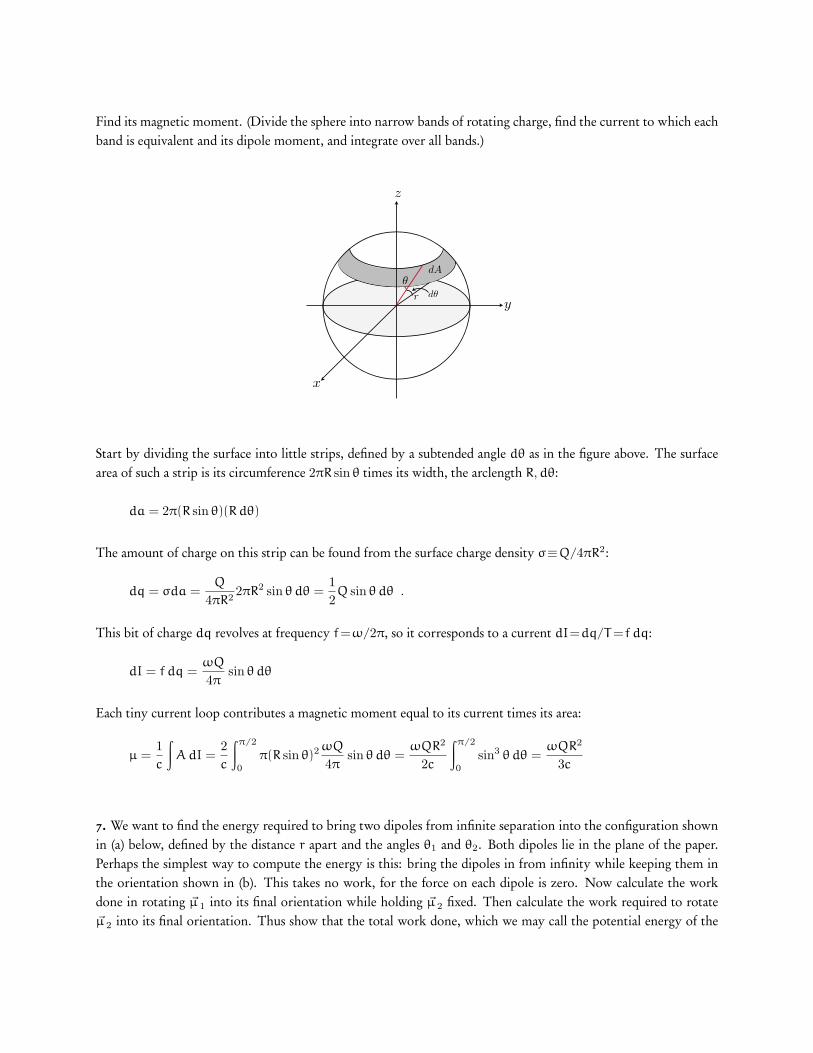
Find its magnetic moment. (Divide the sphere into narrow bands of rotating charge, find the current to which eachband is equivalent and its dipole moment, and integrate over all bands.)
d!
x
y
z
r
dA
!
Start by dividing the surface into little strips, defined by a subtended angle dθ as in the figure above. The surfacearea of such a strip is its circumference 2πR sin θ times its width, the arclength R,dθ:
da = 2π(R sin θ)(R dθ)
The amount of charge on this strip can be found from the surface charge density σ≡Q/4πR2:
dq = σda =Q
4πR22πR2 sin θ dθ =
12Q sin θ dθ .
This bit of charge dq revolves at frequency f=ω/2π, so it corresponds to a current dI=dq/T =f dq:
dI = f dq =ωQ
4πsin θ dθ
Each tiny current loop contributes a magnetic moment equal to its current times its area:
µ =1c
∫A dI =
2c
∫π/2
0
π(R sin θ)2ωQ
4πsin θ dθ =
ωQR2
2c
∫π/2
0
sin3 θ dθ =ωQR2
3c
7. We want to find the energy required to bring two dipoles from infinite separation into the configuration shownin (a) below, defined by the distance r apart and the angles θ1 and θ2. Both dipoles lie in the plane of the paper.Perhaps the simplest way to compute the energy is this: bring the dipoles in from infinity while keeping them inthe orientation shown in (b). This takes no work, for the force on each dipole is zero. Now calculate the workdone in rotating ~µ 1 into its final orientation while holding ~µ 2 fixed. Then calculate the work required to rotate~µ 2 into its final orientation. Thus show that the total work done, which we may call the potential energy of the

system, is
U =µ1µ2 (sin θ1 sin θ2 − 2 cos θ1 cos θ2)
r3(29)
!µ1
!µ !!1
!2
r
!µ1
!µ !
!2
(a)
(b )
The potential of a single dipole in a magnetic field, up to an overall constant (which we can choose to be zero) is
U = −~µ · ~B
Since we are worried about the net work done, the choice of zero for potential energy is irrelevant:
W = Uf − Ui
In the initial configuration, the field due to dipole µ2 at dipole µ1 is
B2 =µ2
r3
The work required to rotate µ1 from a 90◦ orientation to an angle θ1 is thus
W1 = Uf − Ui = −µ1B2 cos(90 + θ1) − 0 = µ1B2 sin θ1 =µ1µ2
r3sin θ1
To next rotate µ2, we break up the field from µ1 into two parts, along the radial and angular parts (see problem 2;an infinitesimal current loop is essentially a magnetic dipole!)
B1 =2µ1 cos θ1
r3B ′
1 =µ1 sin θ1
r3.

�µ2
θ2
r
�µ1
�µ2 B2
θ1�µ1
µ1sin
θ1
µ1cos
θ1
B1
B�1
The work to rotate µ2 is then
W2 = Uf − Ui = [−µ2B1 cos θ2 − µ2B′1 cos(90 + θ2)] − [−µ2B
′1 cos π]
= −µ2B1 cos θ2 + µ2B′1 sin θ2 − µ2B
′1
= −2µ1µ2
r3cos θ1 cos θ2 +
µ1µ2
r3sin θ1 sin θ2 −
µ1µ2
r3sin θ1 .
the total work is thus the sum of the work required to rotate both dipoles:
W = W1 + W2 =µ1µ2
r3(sin θ1 sin θ2 − 2 cos θ1 cos θ2) .
8. A metal crossbar of mass m slides without friction on two long parallel rails a distance b apart. A resistor R isconnected across the rails at one end; compared with R, the resistance of the bar and rails is negligible. There is auniform field ~B perpendicular to the plane of the figure. At time t= 0, the crossbar is given a velocity vo towardthe right. What happens then? (a) Does the rod ever stop moving? If so, when? (b) How far does it go? (c) Howabout conservation of energy? Hint: first find the acceleration, and make use of an instantaneous balance of power.
X
X
X
X
X
X
X
X
X
X
X
X
X
X
X
X
X
X
Bin X
X
X
X
X
X
X
X
X
X
X
X
X
X
X
X
X
X
X
X
vo
bR
Figure 1: Problem 5
Let the position of the rod be x, with the x direction being to the right, and the y direction upward. This meansthe magnetic field points in the −z direction, giving in a magnitude −B. At time t = 0, we will say the rod hasvelocity vo and position xo. For any time t, we will just call the velocity v and position x, since we don’t knowwhat they are yet.

As we discussed in class, the charges in the moving conducting bar will experience a magnetic force Fb =qvB. Thiswill cause positive charges to experience a force in the y direction, and negative charges in the −y direction. Sincecharges are mobile in a conductor, this will cause positive charge to accumulate at the top of the rod, and negativecharge at the bottom. This charge separation, over the width of the rod b, will lead to an electric field across therod over the distance b. This electric field will serve to pull the charges back together.
Once an equilibrium is reached, the magnetic force separating the charges will be perfectly balanced by the electricforce pulling them back together:
Fb = qvB = Fe = qE =⇒ E = vB (30)
Since electric field in a conductor is necessarily uniform, this implies a constant potential difference between theendpoints of the rod, given by ∆V =Eb, with the top of the rod being at the higher potential (since positive chargeaccumulates there). Thus,
∆V = Bvb (31)
The induced voltage - which is also applied to the resistor, since the rails are perfectly conducting - will lead to acounterclockwise current in the loop.
∆V = Bbv = IR
The presence of a current in the conducting rod will lead to a magnetic force. Since the field is into the page (−z
direction), and the current is flowing up through through the rod (y direction), the force must be in the y direction.
~F B = I~L × ~B = IbB y× (−z) = −IbB x = −B2b2v
R= ma
Recall that the direction of ~L is the same as the direction of the current. Since the magnetic force is the only forceacting on the rod (in the absence of friction), it must also give the acceleration of the rod, as indicted in the laststep. Incidentally, we could have gotten here much more quickly with a little intuition. If we recognize that theremust be a current flowing in the resistor due to the induced voltage caused by the motion of the rod, then we knowthere is power dissipated in the resistor. This power must be the same as that supplied to the rod. The mechanicalpower is ~F · ~v , and the electrical power is I2R. Conservation of energy requires that these two powers be equal,which along with the motional voltage leads directly to the equation above.
Anyway: now we have a small equation relating v and its rate of change, dv/dt=a. We can solve it by separationof variables, which is totally cool since none of our quantities are zero. Dividing by zero is not cool.
−B2b2v
R= m
dv
dtmR
B2b2
dv
v= −dt

Now we’ve got something we can integrate. Our starting condition is velocity vo at time t== 0, going until somelater time t where the velocity is v.
v∫vo
mR
B2b2
dv
v=
t∫0
−dt
mR
B2b2ln v
∣∣∣∣vvo
= −t
∣∣∣∣t0
mR
B2b2ln
v
vo= −t
=⇒ v = voe−t/τ with τ =mR
B2b2
The velocity is an exponentially decreasing function of time, which means it never stops moving - the velocityapproaches, but does not reach, zero. The rod will also approach a final target displacement in spite of this fact,which we can find readily by integrating the velocity.
∆x =
∞∫o
v dt =
∞∫o
voe−t/τ = vo
(−τe−t/τ
) ∣∣∣∣∞o
= voτ =mRvo
B2b2
Once again, if you note that 1 T=1 kg/s2 · A and 1 V · 1 A=1 W, you should be able to make the units come outcorrectly.
Finally, we can calculate the total electrical energy expended. The electrical power dissipated in the resistor isP =dU/dt= I2R, so the tiny bit of potential energy dU expended in a time dt is dU= I2R dt. We can integrateover all times to find the total potential energy.
U =
∞∫0
I2R dt =
∞∫0
(Bbv
R
)2
R dt =B2b2
R
∞∫0
v2 dt
=B2b2v2
o
R
∞∫0
e−2t/τ dt =B2b2v2
o
R
(−
τ
2e−2t/τ
) ∣∣∣∣∞0
=B2b2v2
o
R
(mR
2B2b2
)
=12mv2
0
As we would expect from conservation of energy, all of the initial kinetic energy of the conducting bar ends updissipated in the resistor.