problem 29 - university of british columbiamccutche/phys153_lec/lecture13_08w_term2.pdf · but by...
TRANSCRIPT

Problem 29.53
A flexible circular loop 6.50 cm in
diameter lies in a magnetic field with
magnitude 0.950 T, directed into the
plane of the page, as shown. The loop
is pulled at the points indicated by the
arrows, forming a loop of zero area in
0.250 s.
(a) Find the average induced emf in the
circuit.
(b) What is the direction of the current in
Fig. 29.46
PHYS 153 08W 1PHYS 153 08W 11PHYS 153 08W
(b) What is the direction of the current in
R, from a to b, or from b to a? Explain your
reasoning.

A dc generator and back emf in a motor
Fig. 29.10
PHYS 153 08W 2PHYS 153 08W 2PHYS 153 08W 2
In this example, steps are taken to make the emf which is generated always
positive. Due to the commutator, the brushes switch sides when the induced
emf changes direction, and hence the current produced will always be in the
same directions. The ‘bumpiness’ can be smoothed out by using a large
number of coils and commutator segments.
When using the slip rings (ac alternator), the emf had both positive and negative
values, and . With the commutator, the emf is never negative, and the
average value is positive.
0=aveε

This motor’s back emf is just the emf induced by the changing magnetic flux
through the rotating coil. For N coils in the loop,
aveave tBAN |sin| ωωε =
ωπ
ωω ∫
=
2/
0sin
|sin|
T
ave
tdtt where ω
π=2
T
πω
π
πω
ωπ
ωω
ωπ
ω ωπω
π
2]0cos)[cos1(|cos)1(sin0
0 =−−
=−
=∫ ttdt
PHYS 153 08W 3PHYS 153 08W 3PHYS 153 08W 3
ωωω
πω
εBAN
ave
2=∴
Slidewire generator (motional emf)
Fig. 29.11
This is a simple version of a dc generator,
and although it is not very useful practically,
it is useful pedagogically.

The cause of the induced emf is the increase in area.
Choose to point into the page, parallel to . →
A→
B
BABAABB ==•=Φ→→
φcos
BLvdt
LvdtB
dt
dAB
dt
d B −=−=−=Φ
−=∴ε
Note, to oppose the change that is causing the induced emf, the current
must flow counterclockwise. (Check this with the R.H. rule).
If v is constant, and the rod stays on the rails, the emf generated will be constant.
PHYS 153 08W 4PHYS 153 08W 4PHYS 153 08W 4
If v is constant, and the rod stays on the rails, the emf generated will be constant.
This is a d.c. generator.
But we now have a current in a conductor
which is moving in a magnetic field. Hence
There will be a force on it pointing opposite
to . Thus, work must be done to move
the rod to the right.
Fig. 29.12
v
For a resistance in the circuit, energy
will be dissipated from the losses.
RRI 2

How does the work done compare to the energy losses?
To keep the rod moving, a force , equal to the resisting force, must be applied in
the direction of .
→
Fv
The force is given byR
vLBLB
R
BLvLB
RILBF
22||====
ε
Hence, the rate at which work is done is R
vLBFv
222
=
The energy dissipated is R
vLBR
R
BLvRI
22222 )( ==
PHYS 153 08W 5PHYS 153 08W 5PHYS 153 08W 5
RR
The work done is equal to the energy dissipated.
The situation of the sliding rod in the slidewire generator can be analyzed in a
different way. As the rod in Fig. 29.11 moves to the right, charged particles
in it experience a force
→→→
= BxvqF which creates an excess of positive charge at the top of the rod.
(Assume that the rails on which the rod slides are insulators for the moment).
An electric field will then be created which points from top to bottom on the rod.
In equilibrium, the downward electrostatic force will equal the upward magnetic
force.
qvBqE =The difference in potential between top and bottom,
vBLELVVV bottomtop ==−=∆
The moving rod has become like a battery, with a potential difference between
the ends, and hence a source of emf. When the rest of the circuit (here, just a
PHYS 153 08W 6PHYS 153 08W 6
the ends, and hence a source of emf. When the rest of the circuit (here, just a
rectangle) is a conductor, this emf drives current around it, in the counter-
clockwise direction shown.
vBLV ==∆ ε (motional emf)
The emf (magnitude and direction) has been determined now in two
ways, Faraday’s law / Lenz’s law, and by analysis of the motion of the rod
(motional emf). Both are the same.
ε

We can generalize this.
Suppose the circuit is not a simple rectangle, and that the magnetic field is not
perpendicular to the plane of the area, and not uniform.
From above,
→→→
= BxvE
→→→→→
•=•= ldBxvldEd )(ε→→→
•=∴ ∫ ldBxv )(ε (motional emf)
PHYS 153 08W 7PHYS 153 08W 7
∫This is equivalent to the original statement of Faraday’s law,
dt
d BΦ−=ε →
B
I
Consider again a conducting loop which
encloses a magnetic field which can vary
with time.

If the strength of the field shown is increasing in time, then an emf will be
induced which drives a current in the direction shown.
What makes the charges move so that a current flows?
The conductor is not moving in a magnetic field, so there are no
magnetic forces. The conductor may not even be in a magnetic field
(but just encloses it).
What is the only thing that makes electric charges move? It is an electric
field. So the changing magnetic field must induce an electric field. →
B→
E→
EElectric fields are not only produced by charges,
but by time varying magnetic fields.
PHYS 153 08W 8PHYS 153 08W 8
→
E
Ebut by time varying magnetic fields.
dt
dldE BΦ−==•→→
∫ ε
Integrating around the loop, we get
If the loop is a conductor, and a charge q moves once
around the loop, then there is work done.
εqldEq =•→→
∫
This electric field is very different from the electrostatic field that we first
studied.
Recall, for an electrostatic field, 0=•→→
∫ ldE
Such a field is conservative, and for conservative fields we could define
a potential.
Our new electric field, produced by a changing magnetic field, is
nonconservative, and is a nonelectrostatic field.
However, the fundamental force law, , applies to both
fields., conservative and nonconservative.
→→
= EqF
PHYS 153 08W 9PHYS 153 08W 9
fields., conservative and nonconservative.
Consider this. Suppose the loop in the previous slide is nonconducting. In
fact, suppose the loop is just imaginary. Is an electric field still produced?
Applications of magnetically induced electric fields.
•Power generating stations
•Alternators in cars
•Computer disk drives
•Magnetic tapes

Problem 29.7
The current in the long straight wire AB
is upward and is increasing steadily at a
rate
(a) At an instant when the current is ,
what are the magnitude and direction of
the field at a distance r to the right of
the wire?
(b) What is the flux through the narrow
shaded strip?
idt
di
→
B
BdΦ
PHYS 153 08W 10PHYS 153 08W 10
Fig. 29.27
(c) What is the total flux through the loop?
(d) What is the induced emf in the loop?
What is the direction?
(e) If a=12.0 cm, b=36.0 cm, L=24.0 cm,
and = 9.60 A/s, calculate the value of
the induced emf. dt
di

Problem 29.67
The magnetic field , at all points within
a circular region of radius R, is uniform in
space and directed into the plane of the page.
(the region could be a cross section inside the
windings of a long, straight solenoid). If the
magnetic field is increasing at a rate ,
what are the magnitude and direction
of the force on a stationary positive point charge
q located at points a, b, and c?
→
B
dtBd→
Fig. 29.54
PHYS 153 08W 11
Fig. 29.54
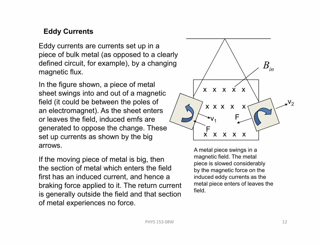
Eddy Currents
v1
v2
F
x x x x x
x x x x x
inB
Eddy currents are currents set up in a
piece of bulk metal (as opposed to a clearly
defined circuit, for example), by a changing
magnetic flux.
In the figure shown, a piece of metal
sheet swings into and out of a magnetic
field (it could be between the poles of
an electromagnet). As the sheet enters
or leaves the field, induced emfs are
PHYS 153 08W 12
Fx x x x x
A metal piece swings in a
magnetic field. The metal
piece is slowed considerably
by the magnetic force on the
induced eddy currents as the
metal piece enters of leaves the
field.
or leaves the field, induced emfs are
generated to oppose the change. These
set up currents as shown by the big
arrows.
If the moving piece of metal is big, then
the section of metal which enters the field
first has an induced current, and hence a
braking force applied to it. The return current
is generally outside the field and that section
of metal experiences no force.

If the piece of metal has slots cut into it, the
large eddy current loops are broken up, and
the braking action greatly reduced.
Eddy currents can have undesirable effects.
Eddy currents in cores of transformers (which
we will study later) waste energy through
RI 2 heating losses.
Advantages:
• damp unwanted oscillations, for
PHYS 153 08W 13
If the metal sheet has of slots cut
into it, the eddy currents are
confined to narrow slots and
are greatly reduced. The braking
on the ‘pendulum’ is greatly
reduced.
• damp unwanted oscillations, for
example in sensitive mechanical
balances.
• magnetic braking in some rapid
transit cars. Electromagnets positioned
in the car over the rails can induce eddy
currents in the rails.
One particularly interesting example of the
effects if eddy currents occurs in Io, the
large moon of Jupiter.
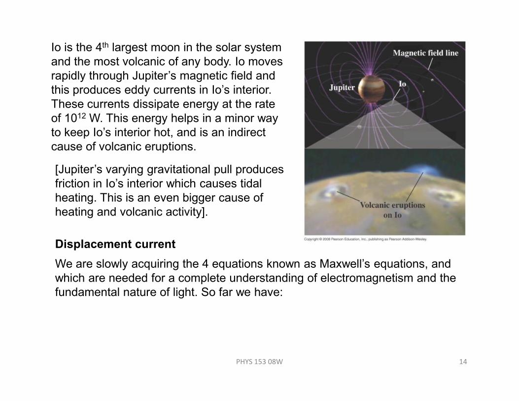
Io is the 4th largest moon in the solar system
and the most volcanic of any body. Io moves
rapidly through Jupiter’s magnetic field and
this produces eddy currents in Io’s interior.
These currents dissipate energy at the rate
of 1012 W. This energy helps in a minor way
to keep Io’s interior hot, and is an indirect
cause of volcanic eruptions.
[Jupiter’s varying gravitational pull produces
friction in Io’s interior which causes tidal
heating. This is an even bigger cause of
PHYS 153 08W 14
heating. This is an even bigger cause of
heating and volcanic activity].
Displacement current
We are slowly acquiring the 4 equations known as Maxwell’s equations, and
which are needed for a complete understanding of electromagnetism and the
fundamental nature of light. So far we have:

0εenclQ
AdE =•→→
∫ (Gauss’s law)
0=•→→
∫ AdB (Gauss’s law for magnetism)
enclildB 0µ=•→→
∫ (Ampere’s law)
It turns out that the 3rd equation (Ampere’s law) is incomplete and we must
→→
•=Φ
−= ∫ ldEdt
d Bε (Faraday’s law)
PHYS 153 08W 15
generalize Ampere’s law by completing it.
Fig. 29.22
Imagine a circuit with a charging
capacitor. Current flows into
the left hand side, and out the right. The
electric field increases in the space
between the capacitor plates.
Ci
→
E

Apply Ampere’s law to the circular path shown.
→→
• ldB around the path shown equals (where is the conduction
current flowing through the area bounded by that path). In this case, the
conduction current flows through the flat area bounded by the path.
Ci0µ Ci
CiBut the bulging surface to the right is also an area bounded by the same
path. The current through that surface is zero. So, Ampere’s law seems to
be fine for the flat surface but not for the bulging surface.
Ampere’s law is incomplete. There is an equivalent current between the
PHYS 153 08W 16
Ampere’s law is incomplete. There is an equivalent current between the
capacitor plates and it is related to the changing field.
For a parallel plate capacitor, with plates of area separated by d, and
filled with material of permittivity
→
E
The charge on the capacitor at any time is
ε
d
AC
ε=
A
EEAEdd
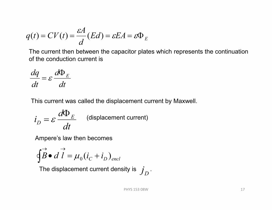
AtCVtq Φ==== εε
ε)()()(
The current then between the capacitor plates which represents the continuation
of the conduction current is
dt
d
dt
dq EΦ= ε
This current was called the displacement current by Maxwell.
PHYS 153 08W 17
dt
di ED
Φ= ε (displacement current)
Ampere’s law then becomes
enclDC iildB )(0 +=•→→
∫ µThe displacement current density is .
Dj
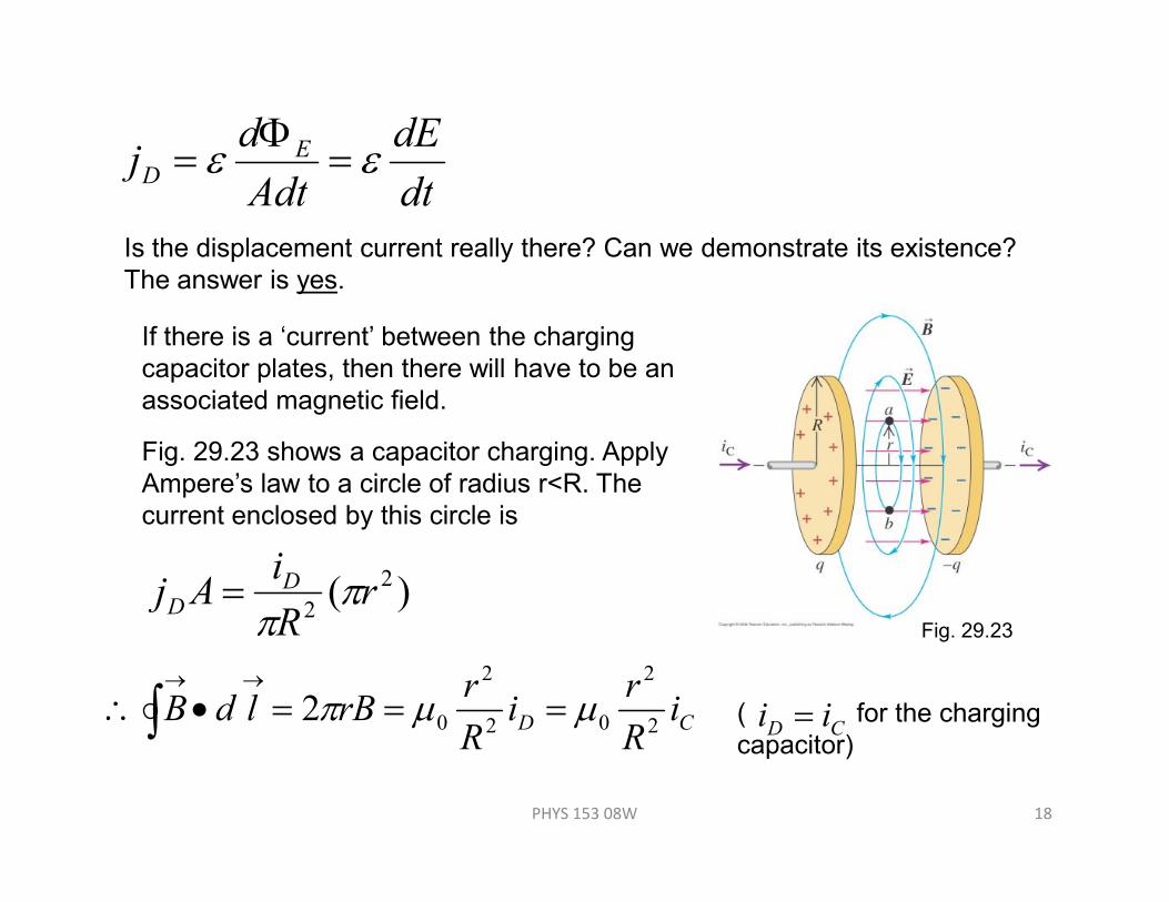
dt
dE
Adt
dj ED εε =
Φ=
Is the displacement current really there? Can we demonstrate its existence?
The answer is yes.
If there is a ‘current’ between the charging
capacitor plates, then there will have to be an
associated magnetic field.
Fig. 29.23 shows a capacitor charging. Apply
PHYS 153 08W 18
Fig. 29.23
Fig. 29.23 shows a capacitor charging. Apply
Ampere’s law to a circle of radius r<R. The
current enclosed by this circle is
)( 2
2r
R
iAj D
D ππ
=
CD iR
ri
R
rrBldB
2
2
02
2
02 µµπ ===•∴→→
∫ CD ii =( for the charging
capacitor)
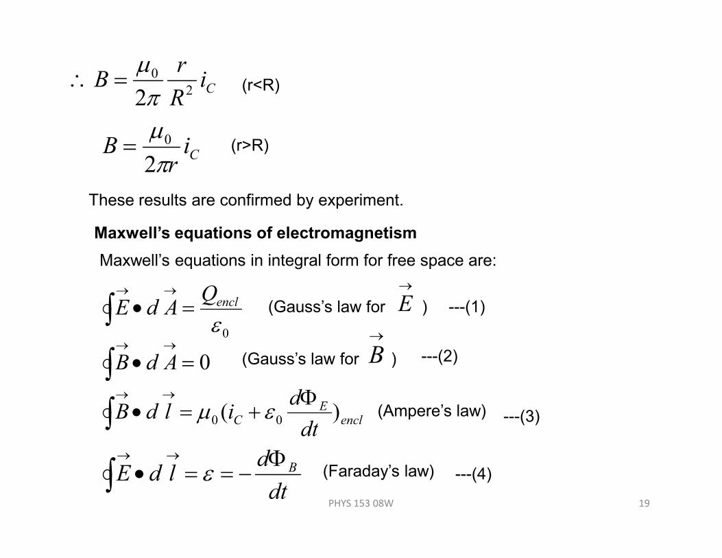
CiR
rB
2
0
2πµ
=∴ (r<R)
Cir
Bπµ2
0= (r>R)
These results are confirmed by experiment.
Maxwell’s equations of electromagnetism
Maxwell’s equations in integral form for free space are:
→
PHYS 153 08W 19
0εenclQ
AdE =•→→
∫ (Gauss’s law for )
→
E
0=•→→
∫ AdB (Gauss’s law for )
→
B
enclE
Cdt
dildB )( 00
Φ+=•
→→
∫ εµ (Ampere’s law)
dt
dldE BΦ−==•→→
∫ ε (Faraday’s law)
---(1)
---(2)
---(3)
---(4)
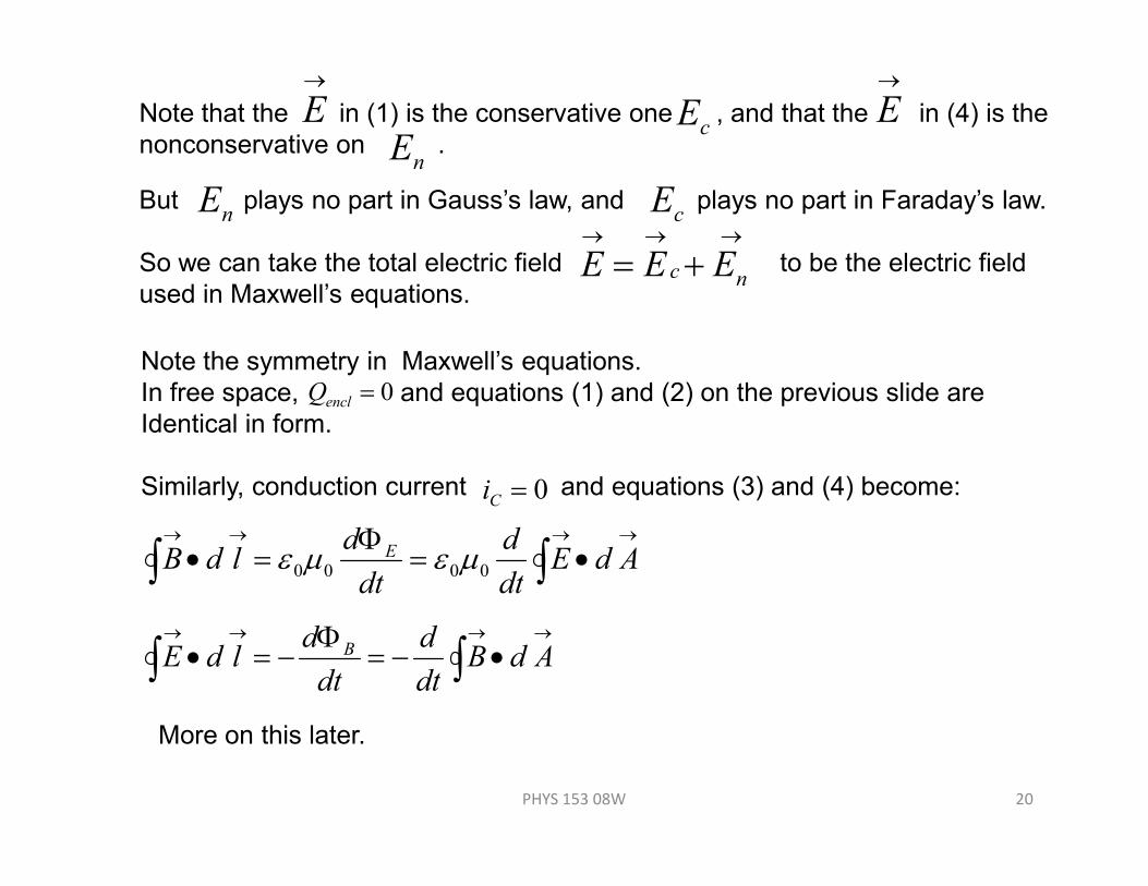
Note that the in (1) is the conservative one , and that the in (4) is the
nonconservative on .
→
E→
EcE
nE
But plays no part in Gauss’s law, and plays no part in Faraday’s law.
So we can take the total electric field to be the electric field
used in Maxwell’s equations.
nE cE→→→
+= nc EEE
Note the symmetry in Maxwell’s equations.
In free space, and equations (1) and (2) on the previous slide are
Identical in form.
0=enclQ
PHYS 153 08W 20
Similarly, conduction current and equations (3) and (4) become: 0=Ci
→→→→
•=Φ
=• ∫∫ AdEdt
d
dt
dldB E
0000 µεµε
→→→→
•−=Φ
−=• ∫∫ AdBdt
d
dt
dldE B