pro-moteweb.science.mq.edu.au/~rdale/teaching/itec810/2009h1/... · · 2009-06-05the glovepie...
TRANSCRIPT
Pro-MOTE 3D Interactive Whiteboard for Scientific
Collaboration
Shweta Jain Department of Computing
Macquarie University Sydney, Australia
Under Supervision of
Manolya Kavalki Department of Computing
Macquarie University Sydney, Australia

2 |
Abstract
In the era of internet, virtual collaboration for presentation, lectures or discussion, through Microsoft Meeting, VNC, or virtual whiteboard are common forms of communication in research and industry. Most of these present technologies focus on 2D virtual environment depicting a chalk-and-board classroom. However with the advent of 3-D visualization techniques, and gesture recognition methods, it’s possible to create a 3D virtual environment, which can be used for more intuitive communication. This work proposes to create a 3D whiteboard, where several collaborators can draw and edit 3-D objects using hand-gestures. In this paper, we discuss the system architecture for the development of this 3D whiteboard (Pro-MOTE), integrating Wiimote for motion capture, GlovePIE as a platform for algorithmic computation and interface builder, and Blender to render/recreate the 3D objects intended to be drawn. Interactive nature of this 3-D whiteboard makes it possible for multiple users to edit these 3D objects simultaneously. These virtually created 3D objects can then be viewed by special eyewear and used by any scientific community for discussion, debates, education and collaboration.
3 |
Acknowledgments
I would like to express my gratitude towards my advisor Manolya Kavakli for her kind and patient advice and support. I would like to thank John Porte for helping me understand Wiimote interface with Windows system and GlovePIE.
I would also like to thank Robert Dale for useful feedback on this work. And also I would like to thanks to all those who gave me the possibility to complete this work.
4 |
Table of Contents Abstract ......................................................................................................................................2
1. Introduction ........................................................................................................................5
1.1 Goal: [What?] ...................................................................................................................5
1.2 Significance: [Why?] ......................................................................................................5
1.3 Challenges [How?]: ............................................................................................................6
1.4. Report Structure: ..............................................................................................................6
2. Literature Review ................................................................................................................8
2.1 Scientific collaboration: .....................................................................................................8
2.2 Gesture Recognition ..........................................................................................................8
3. Methodology .....................................................................................................................15
3.1. Motion Capture: .............................................................................................................15
3.2. Gesture recognition: .......................................................................................................15
3.3 3-D Object Recreation: ....................................................................................................16
3.4 Efficient Remote communication:....................................................................................16
3.5. The Pro-MOTE: ...............................................................................................................17
4. Implementation.................................................................................................................18
4.1 The Wiimote: ...................................................................................................................18
4.2. The GlovePIE ..................................................................................................................20
4.3 Blender: ...........................................................................................................................24
4.4 Integrated Pro-MOTE System: .........................................................................................33
5. Experimentation ................................................................................................................34
5.1 Lab Experimentation: ......................................................................................................34
5.2 Human Ethics approval: ...................................................................................................35
6. Conclusion and Future work ..............................................................................................36
References ................................................................................................................................37
Appendix - A..............................................................................................................................40

5 |
1. Introduction
1.1 Goal: [What?]
Pro-MOTE is an interactive multi-user virtual 3-D whiteboard. To its users, Pro-MOTE offers a
platform for a more intuitive distant communication with 3-D visual aids. Using this system,
researchers far away can engage in communication as if they are in the same room, and can
view and edit diagrams, flow-charts, a virtual 3-D space.
1.2 Significance: [Why?] We are just at the beginning of an era of essential partnerships, alliances, and coalitions. We are learning to build community beyond the walls of the organization, with the same kind of initiative and energy we have used in building the organization within the walls.
Frances Hesselbein
Collaboration expedites solutions, reduces re-invention, reaches beyond the boundaries of
individual knowledge and finally helps innovations. Problem solving is often accelerated with
involvement of multiple people with relevant expertise. However, it is not always possible to
gather all the relevant people in the same room. Distant communication, therefore assume a
significant importance for collaborative work.
Communication technologies relevant to scientists and collaborators can be broadly categorized as text based, voice based, voice and video based, and shared platform based. While the conventional text/voice/video based technologies form the base of communication, there has been significant development in recent years to create common platforms which can be viewed or edited by several collaborators, either asynchronously or in ‘real-time’. Examples of such asynchronous shared platforms include “Google Docs”, an online document sharing engine; Wiki, where multiple users can contribute development of single or multiple web-pages, resulting in truly worthwhile projects such as Wikipedia. Real-time communication platforms include Group Chat clients, where single window is duplicated by each client, and can be controlled by multiple users; a VNC client-server system,
6 |
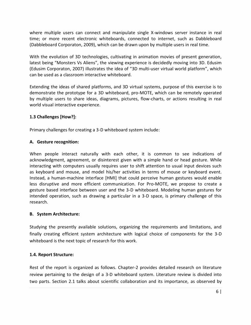
where multiple users can connect and manipulate single X-windows server instance in real time; or more recent electronic whiteboards, connected to internet, such as Dabbleboard (Dabbleboard Corporaton, 2009), which can be drawn upon by multiple users in real time. With the evolution of 3D technologies, cultivating in animation movies of present generation, latest being “Monsters Vs Aliens”, the viewing experience is decidedly moving into 3D. Edusim (Edusim Corporaton, 2007) illustrates the idea of “3D multi-user virtual world platform”, which can be used as a classroom interactive whiteboard. Extending the ideas of shared platforms, and 3D virtual systems, purpose of this exercise is to demonstrate the prototype for a 3D whiteboard, pro-MOTE, which can be remotely operated by multiple users to share ideas, diagrams, pictures, flow-charts, or actions resulting in real world visual interactive experience. 1.3 Challenges [How?]:
Primary challenges for creating a 3-D whiteboard system include: A. Gesture recognition: When people interact naturally with each other, it is common to see indications of acknowledgment, agreement, or disinterest given with a simple hand or head gesture. While interacting with computers usually requires user to shift attention to usual input devices such as keyboard and mouse, and model his/her activities in terms of mouse or keyboard event. Instead, a human-machine interface [HMI] that could perceive human gestures would enable less disruptive and more efficient communication. For Pro-MOTE, we propose to create a gesture based interface between user and the 3-D whiteboard. Modeling human gestures for intended operation, such as drawing a particular in a 3-D space, is primary challenge of this research.
B. System Architecture:
Studying the presently available solutions, organizing the requirements and limitations, and
finally creating efficient system architecture with logical choice of components for the 3-D
whiteboard is the next topic of research for this work.
1.4. Report Structure:
Rest of the report is organized as follows. Chapter-2 provides detailed research on literature
review pertaining to the design of a 3-D whiteboard system. Literature review is divided into
two parts. Section 2.1 talks about scientific collaboration and its importance, as observed by

7 |
various researchers. Section 2.2 details the present systems and technologies for hand gesture
recognition. Chapert-3 derives the methodology we adopt for the design of Pro-MOTE, based
on the discussions on presently available technology choices. Chapter-4 first provides details of
the components used for the implementation of Pro-MOTE, and then illustrates how these
components are integrated to create Pro-MOTE system. Chapter-5 outlines the
experimentations performed using Pro-MOTE. We conclude with list of achievements and
future work in Chapter-6. References are included in the end for further study, and Appendix
section goes into details of some of the implementation scripts and programs.

8 |
2. Literature Review
2.1 Scientific collaboration: "Collaboration among organizations is rapidly becoming common in scientific research as globalization and new communication technologies make it possible for researchers from different locations and institutions to work together on common projects." (Shrum et al, 2007).
Advances in scientific collaboration have been well documented and researched in the past years (Edadi and Utterback, 1984; Hara et al, 2003). Concepts such as "Collaboratories”, aptly defined as “centers without walls” (Johnston, 2000), have been proposed on various forums for organized approach towards joint scientific efforts. Social engineering and improved means for distant communication, to exchange ideas and share resources and tools, remain the central theme behind such efforts. Rapid growth in scientific innovations in last few decades, as compared to the previous ones, has been largely attributed to the better and faster and more intuitive means of communication. Further, in the era of internet, innovators can share knowledge, resources and tools with their peers, faster and more effectively, regardless of physical distances. Means of interaction have been transformed from text, voice and video based communication to virtual platforms, which allow multiple users to manipulate and control a single platform. Most of the present virtual platforms focus on 2-D environments with conventional inputs from devices such as mouse and keyboard (Shrum et al, 2007). Developments in the field of virtual reality (such as, Kavakli, 2008; Gao and Kavakli, 2006), specifically, hand gesture recognition, and 3D rendering and viewing, make it possible to communicate remotely with gestures in a 3D virtual world, making the interaction more intuitive. Our aim is to develop 3D Virtual Whiteboard (Pro-MOTE) as a platform for scientists to interact with each other using a virtual pointer, so that the diagram created in real time can be displayed on a head mounted display worn by each user. Pro-MOTE is intended to improve the quality of collaboration between remotely located professional and research groups. 2.2 Gesture Recognition
People frequently use gestures to communicate. Gestures are used for everything from pointing at a
person to get their attention to conveying information (Adam Kendon, 1990). Evidence indicates that

9 |
gesturing does not simply decorate spoken language, but is part of the language generation process (D.
McNeill et al, 1982)
Primary goal of gesture recognition research is to create a system which can identify specific
human gestures and use them to convey information or for device control. Gestures can
originate from any bodily motion or state but commonly originate from the face and hand.
Gesture Recognition enables humans to interface with the machine and interact naturally,
rather than limited to mice-movements, or touch screen based controls.
As a topic of interest to sociologist, linguist, mathematicians, and computer scientists, several
theories have been proposed for natural definition of gestures and that to capture those
gestures in most efficient ways, and further use them to build a better Human Machine
Interface [HMI]. This study particularly deals with hand gesture recognition.
While interpretation of hand gesture to human mind is largely intuitive and vague, definite
recognition of same by machine needs large amount of computations. Recognition of gesture
with a system would primarily comprise of three components, the hardware to sense the
gesture, the logic or algorithm, to convert the gestures into lexicon, finally the purpose or
outcome of the system, which could be either to control another device or system.
Accordingly, the rest of the study is organized in four sections. Next section [II] deals with
various devices and techniques available for hand gesture recognition, section-III outlines
various software methods used to accurately interpret the gestures. Section-IV presents the
application and systems using such gesture recognition. Section-V details the issue at hand,
namely 3D whiteboard collaboration, and justifies the choice of Wii remote system for the
same. Section VI provides specifications of Wii remote.
Since we focus more on the use of Wii-remote system with the application in mind to build 3D
whiteboard collaboration systems, the details of several parallel systems and application is
omitted in the interest of usefulness. Following material still tries to capture the broader areas
of interests and present and past works in the exciting field of gesture recognition.
2.1.1. Hand Gesture sensing technologies:
Broadly, existing sensing techniques for hand gesture recognition and interaction could be
categorized into three main groups: vision-based, EMG-based, and movement-based
techniques.

10 |
A. Vision Based
Vision-based approach comprises of one or more cameras which collect images of the user’s
hands. The cameras grab an arbitrary number of images per second and send them to image
processing routines to perform posture and gesture recognition as well as 3D triangulation to
find the hands’ position in space.
Primary performance factors of Vision based approach is to:
i. Placing the cameras such that hands are visible at all times. This includes determine optimum
number of cameras. Larger number of cameras would increase complexity of algorithms, while
a smaller number could reduce the accuracy of tracking. Kumo (1998) and Utsumi (1997) use
multiple cameras effectively in the context of 3D object manipulation and 3D scene creation,
respectively. While Starner et al (1998) shows use of one camera for hand posture recognition.
ii. Making the hands more visible to camera: This could include wearing LEDs (Sturman and
Zeltzer, 1994), or colored gloves (Hasanuzzaman et al, 2004) for easier recognition. One of the
best vision systems for tracking the naked hand was Krueger’s VIDEODESK system (Krueger,
1996), although it required complex image-processing hardware. He was able to track hand
silhouettes in order to create simple 2D and 3D shapes. Utsumi (1997) also tracked the naked
hand in his 3D scene creation system.
Vision based systems are sensitive to user’s circumstances such as background texture, color,
and lighting. This limits their extensive application. Commercial applications based on vision
based systems include motion sensing cameras with Sony Playstation, and Microsoft XboX
systems. However the usage of such system was restricted to simpler games requiring less
precise gesture recognition.
B. EMG Based
EMG measures electrical currents that are generated in a muscle during its contraction and
represent neuromuscular activities. EMG can also be used to sense isometric muscular activity
which does not translate into movement. This makes it possible to classify subtle motionless
gestures and to control interfaces without being noticed and without disrupting the
surrounding environment. On the other hand, one of the main difficulties in analyzing the EMG
signal is due to its noisy characteristics. Compared to other bio-signals, EMG contains
complicated types of noise that are caused by, for example, inherent equipment noise,
electromagnetic radiation, motion artifacts, and the interaction of different tissues. Hence,
preprocessing is needed to filter out the unwanted noises in EMG. (Oskoei, 2007; Costanza,
2005).

11 |
C. Movement Based
Movement-based approach utilizes different sensors to measure movement. Most popular
being are Glove and accelerometers.
i. Glove Based
Glove-based gesture interaction is a typical movement-based technique and it achieves good
performance especially in sign language recognition. In this approach user is required to wear a
cumbersome data glove to capture hand and finger movement.
Instrumented gloves measure finger movement through various kinds of sensor technology.
These sensors are embedded in a glove or placed on it. One of the first instrumented gloves
described in the literature was the ‘Sayre Glove’ developed by Thomas Defanti and Daniel
Sandin in a 1977 project for the National Endowment of the Arts (Defanti, 1997). This glove
used photocell technique to create 7 DOF [Degrees of Freedom]. Glove technology evolved
through Photocells, flexible phototubes, magnetic sensors, ultrasonic sensors. Current sensor
technology on glove uses analog-to-digital converters with precision sensing. One of the least
expensive gloves on the market today is the 5DT Data Glove[TM] developed by Fifth Dimension
Technologies. This glove uses five fiber optic sensors to measure the overall flexion of the four
fingers and the thumb; according to the specifications (Meta Motion. 2009), these sensors can be
sampled at ~400 Hz with eight bits of precision.
Since Gloves allow movement tracking of each finger independently including the bending of
fingers, large number of gestures can be represented and captured by the same. However
primary disadvantage of such systems is the cumbersome and glove.
ii. Accelerometer Based
An accelerometer measures the acceleration and gravity it experiences. Basically an
accelerometer behaves as a damped mass on a spring. When the accelerometer experiences an
external force such as gravity, the mass is displaced until the external force is balanced by the
spring force. The displacement is translated into acceleration. With the advent of MEMS [micro
electro-mechanical systems] technology, accelerometers can be integrated into small handheld
devices.
Modern accelerometer consists of a cantilever beam with seismic mass, damped against
residual gas. Under the influence of external accelerations the proof mass deflects from its
neutral position. This deflection is measured in an analog or digital manner. Most commonly,
the capacitance between a set of fixed beams and a set of beams attached to the proof mass is
measured. This method is simple, reliable, and inexpensive. Integrating piezo-resistors in the

12 |
springs to detect spring deformation, and thus deflection, is a good alternative, although a few
more process steps are needed during the fabrication sequence. For very high sensitivities
quantum tunneling is also used; this requires a dedicated process making it very expensive.
Optical measurement has been demonstrated on laboratory scale (Analog Devices, 2009).
Accelerometers-based [ACC] approach is now more popular movement-based technique.
Accelerometers can be made easy to wear and are helpful in providing information about hand
movements. Several commercial products including Apple iPhone, Nintedo Wii-remote use
accelerometer based technology.
D. Combination
Some recent studies have demonstrated use of multiple technologies simultaneously for
efficient gesture recognition. With the combination of EMG and Accelerometer technology,
(Zhang, X. et al, 2009) developed a system for 3D gaming environment.
2.1.2. Algorithms for gesture Recognition
Once the raw data has been collected it’s used to interpret the gestures. This section provides
brief overview of commonly used algorithmic techniques for gesture recognition. Since the
primary project of 3D-collaborative-whiteboard-system doesn't necessarily require elaborate
gesture interpretation, it being simply a conveyor of gestures from one point to other, this
section doesn't go into details of mathematics and models of the algorithms. Principle aim of
this section is to convey the challenges in the field of gesture recognition in general.
A. Extraction and analysis.
One of the simplest and most intuitive methods for gesture-data-interpretation is template
matching. Templates are created with possible data values a resulting equivalent gesture
intended, and are matched with simple Boolean function against the data collected to interpret
the gesture (Cootes et al, 1995). This method is only practical for small set of postures and
possible data values. In feature extraction and analysis, low-level information from the raw data
is analyzed to produce higher-level semantic information and then used to recognize postures
and gestures. One of the first gestural interfaces to use a feature-based system was Rubine’s 2D
single-stroke gesture recognizer (Starner and Pentland, 1996). Various mathematical
techniques such as Principle Component Analysis, Active Shape Models, Causal Analysis etc,
have been discussed in literature over WEB, which serves the purpose of reducing the raw-data
to more manageable measures to further interpret them through pattern matching or learning.

13 |
B. Learning Algorithms
Neural network systems (Fels, 1994) and Hidden Markov Models [HMM] (Mitra and Acharya,
2007) are most commonly used techniques for machine learning, such as to improve the
accuracy of gesture recognition. These are commonly used mathematical and computational
methods for several other computationally expensive problems.
2.1.3. Applications of gesture Recognition:
A. Sign Language:
One of the more intuitive applications for using hand gesture recognition is sign language. A
number of systems have been implemented that recognize various types of sign languages. For
example, Starner was able to recognize a distinct forty word lexicon consisting of pronouns,
nouns, verbs, and adjectives taken from American Sign Language with accuracies of over 90%
(Starner and Pentland, 1996). A system developed by Kadous (1991) recognized a 95 word
lexicon from Australian Sign Language and achieved accuracies of approximately 80%.
Murakami and Taguchi were able to adequately recognize 42 finger-alphabet symbols and 10
sign-language words taken from Japanese Sign Language (Murakami and Taguchi, 1991).
B. Gesture to Speech:
A gesture-to-speech interface could be useful to hearing-impaired people who wish to
communicate with people who do not know sign language. Fels (1994) and Kramer (1989) have
developed systems for converting hand gestures to speech that use gloves to collect the hand
gestures and speech synthesizers for speech output.
C. Presentation:
Baudel and Beaudouin-Lafon (1993) developed an application; they called Charade that uses
hand gesture input to control a computer while giving a presentation. The used DataGlove to
demonstrate gesture based cursor movement on a Mac, which was used to project the
presentation along with a overhead projector.
D. Virtual Environment, Gaming.
One of the earliest and most wide application of gesture recognition in the world of virtual
environment and gaming. Various arcade and simulator games are commercially available
which use some kind of gesture recognition for interactive gaming. Suggestions for Virtual
world applications (Gao & Kavakli, 2006; Szilas et al, 2007), demonstrate use of gestures for
interactive Drama. VE navigation may use hand gestures for say flying or walking through
14 |
virtual world (Mine, 1997). Typically, the user points in the direction he or she wants to go, and
perhaps uses the other hand to control velocity.
Gesture can also be used for Object interaction. Recently, research groups demonstrate use of
various hand gestures for efficiently seeking information about the object of interest in a very
intuitive and natural way (MIT, 2009).
E. 3-D modeling
3D modeling requires the user to create, manipulate and view 3D objects, and creation of these
objects requires the user to specify a particular shape with the hands. For example, Krueger’s
(1996) VIDEODESK system allows the user to create 2D and 3D objects using the silhouette of
the hand and pointing. Manipulating already created models by translation, rotation and scale
operations is also an important part of the modeling process, and he presents a series of
techniques for doing this type of object manipulation. Using 3D hand gestures for modeling is
relatively new and more research is required so that users can take advantage of their natural
everyday movements for creating 3D models.
F. 3D whiteboard collaboration
Virtual collaboration for presentation, lectures or discussion is a very common form of
communication in research and industry. Many commercial application including Microsoft
Meeting, VNC, Virtual whiteboard are available for this purpose. However most of these
applications deal with transfer of 2-dimnestional data, whether drawn on a computer screen or
on a 2-D electronic whiteboard.
With the invent of 3-D viewers, and the Hand Gesture Recognition principles explained earlier,
its possible to communicate via 3-D images and objects drawn by hand gestures. More
complex, yet intuitive visual discussions can be carried out with such systems between
collaborators in research and industry.
For this application a motion based sensor technology for gesture recognition is a natural
choice, for the ease of use and commercial viability. While a glove based motion sensing does
provide more degrees of freedom, only 3 DOF is actually required for a 3D whiteboard, hence a
3-D accelerometer based technology for motion sensing will suffice. Advent and availability of
Wii-controlled using similar technology makes it a natural choice and perhaps significant
motivation for this project.
15 |
3. Methodology
Pro-MOTE has three components: A 3D motion-capture device, software tool to identify the intended 3D objects from the raw motion data, and a system or tools to render/recreate the 3D objects. Previous section explained the methods and tools available for each of these components with their advantages and shortfalls. In this section we outline the methodology used for the implementation of Pro-MOTE. 3.1. Motion Capture: Motion capture could use any of the three popular methods, movement based, EMG-based or vision based. While choosing the method used for a 3-D whiteboard, following primary requirements and limitations were considered.
A. The motion capture device should be able to capture 3-D movement with reasonable accuracy.
B. The device should be least intrusive and hindering to the movements and gestures of the users, for wider usability.
C. The device should not require elaborate setup and equipments. One of the most popular and readily available gesture sensing devices today is the remote used by Wii gaming consoles, popularly known as Wiimote. A Wiimote has primarily two communication channels. IR based control, where buttons on the Wiimote transmit IR signals, and a 3D accelerometer which detects movement of Wiimote in 3D, and transmits the relevant data depicting movement via Bluetooth. Since Wiimote is designed primarily as an input device to gaming console Wii, usability and esthetics has been widely studied for its design. The body of the Wii Remote measures 148 mm (5.83 in) long, 36.2 mm (1.43 in) wide, and 30.8 mm (1.21 in) thick. It fits firmly in hand, and comes with a wristband, which holds the device from avoid accidentally flying off users hand. Wiimote with its features, ease of use and wide availability ensures it as a suitable choice for the controller used for Pro-MOTE. Using Wiimote button and gestures, users of pro-MOTE will be able to draw and edit on a 3-D virtual whiteboard effectively. 3.2. Gesture recognition: Once the hand movement is captured, intended gestures must be recognized and translated. This can be done with the use of software which can connect and interact with Wiimote.

16 |
Software should also provide a programmable platform, so that it can be manipulated to interact with a 3-D vision device, which forms the third component of pro-MOTE. Variety of software and drivers with Wiimote-specific libraries are available use and manipulate Wiimote generated data. One of the most commonly used Wiimote interface is GlovePIE. Glove Programmable Input Emulator (GlovePIE) was created by Carl Kenner, originally for Glove based input devices in Microsoft Windows. Now it has been extended to support a number of unconventional input devices including the Wiimote.
GlovePIE interface can be used to write an application which will be able to recognize certain
gestures as objects, intended to be drawn. For example, circular movement of hand with
Wiimote could be translated into a sphere object. A hand gesture of stroke could be translated
as an erase operation. Using GlovePIE, Wiimote can also be made to emulate a mouse
behavior, thus controlling a 3rd party application running on the same system as GlovePIE.
3.3 3-D Object Recreation:
Once the system is able to capture and recognize 3-D gestures, the gesture is now translated
into an image which can be viewed and edited by all users. There are several systems which can
create a virtual 3D environment. One of such software is Blender. Blender is widely used in
industry and academics for its wide functionalities, efficient graphical reproduction and
programmability, in addition to its available as a freeware.
3.4 Efficient Remote communication:
Pro-MOTE is intended to be used for remote communication. For such real time system, it’s
critical to reduce to system response time for enhanced user experience. To make the
communication faster over internet, the data transfer between the remote systems should be
reduced. Instead of transmitting all the data from the Wiimote, pro-MOTE filters and decodes
user’s intended gesture and command, and transmits only the relevant data to control the
remotely running blender.

17 |
I
N
T
E
R
N
E
T
USER -1
3-D
view 3-D recreation
[Blender]
Gesture sensor
[Wiimote]
Wiimote
Recognition
[GlovePIE]
USER - 2
3-D
view 3-D recreation
[Blender]
Gesture sensor
[Wiimote]
Wiimote
Recognition
[GlovePIE]
Pro-MOTE System
Architecture and usage
model
3.5. The Pro-MOTE:
Integrating the three systems, Wiimote, GlovePIE and blender and using the efficient remote
communication mechanism described above, we intend to create Pro-MOTE. The system
architecture and usability model of Pro-MOTE is illustrates in Fig-xx. Each user of Pro-MOTE has
a 3-D view system with blender, and a Wiimote. Using “Blender” as a 3-D platform [whiteboard]
and Wiimote as an input device, user can draw 3-D diagrams, graphs, flow-charts and any other
3-D object. Input from Wiimote is captured and decoded by GlovePIE running on the same
machine as the blender. GlovePIE converts user gesture inputs into blender commands and
functions which in turn create intended 3-D objects in user’s 3-D view. Further, GlovePIE
transmits these gestures over internet to other users. This data is used to control the blender
running on remote systems, to create or edit the same 3-D objects drawn on the local system.
This way the 3-D whiteboard for the users is synchronized, and represents the same image. Any
of the users now can edit this 3-D whiteboard, which is reflected in the whiteboards for each of
the users.
Figure 1 - Pro-MOTE System Architecture
18 |
4. Implementation
4.1 The Wiimote:
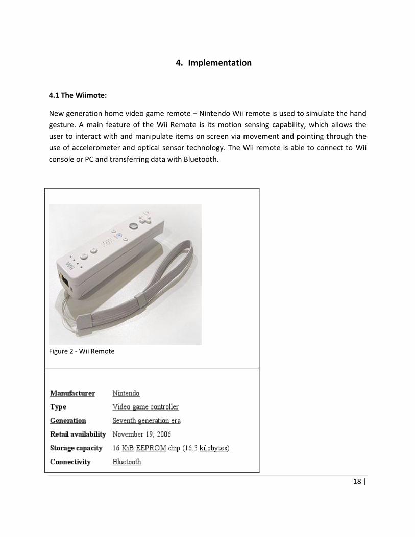
New generation home video game remote – Nintendo Wii remote is used to simulate the hand
gesture. A main feature of the Wii Remote is its motion sensing capability, which allows the
user to interact with and manipulate items on screen via movement and pointing through the
use of accelerometer and optical sensor technology. The Wii remote is able to connect to Wii
console or PC and transferring data with Bluetooth.
Figure 2 - Wii Remote

19 |
A. Functionality:
The main feature of Wii Remote is to sense acceleration along with the three axes through the
use of an ADXL330 accelerometer. With a PixArt optical sensor feature the Wii Remote point
can be determined. The Wii Remote also supports basic audio and rumble functionality. The Wii
Remote also provides an expansion port at the bottom via this various functional attachments
can be added.
B. Connection:
Wii remote is a Bluetooth controller, connecting the Wii remote to any PC or device that
support Bluetooth Human Interface Device (HID) standard can be done via Bluetooth. To open a
connection with device, Wii remote need not require any authentication to establish a
connection with HID standard device. It can be done by switch on the Wii remote into
‘discoverable’ mode by clicking ‘1’ + ‘2’ button on the remote. Once Wii remote is in
discoverable mode, Bluetooth HID driver on the PC or any other host device can find Wii
remote. Once driver is found connection is established. However, if the connection could not be
opened within 20 seconds, the discoverable mode is turn into off and the Wii remote is not able
to connect to any device.
C. Data collection:
Once the connection is established, Wii is able to send data to the host device. The HID
standard allows devices to be self-describing, using HID descriptor block. The block includes as
enumeration of reports that the host device understand. The report include different database
on different service enabled. In general, there are four data chunks and each chunk ahs two
digit number to represent the variable of the chunk. All chunks are to be collected in Wii
remote and combined into a report data, link network packet with alphabetic number. The
number of report send depends on the movement of the remote make within a second. The tag
is introduced to distinguish the report number sent.
D. Sensor Bar:
The Nintendo Wii Sensor Bar is highlighting infrared LEDs. There are two LED slots at the each
side of the back and five LEDs lights in each remote. The farthest away from the centre are
pointed slightly away from the centre and the LEDs closet to the centre are pointed slightly
inward, while others are point straight forward. The sensor bar is powered by the Wii base unit
and most important the cable from the Wii to the sensor bar only carries power, no information
is passed either to or from the sensor bar. The main purpose of setting the sensor bar is to
collect X, Y and Z coordinate using the IR camera inside of the Wii remote, so that Wii remote is

20 |
able to calculate the coordinates of two LED slots. The coordinate of LED slots are static, and it
is not charged so that Wii remote can find the X, Y and Z coordinates of the remote by finding
difference of the current location and original coordinates.
4.2. The GlovePIE Glove Programmable Input Emulator (GlovePIE) was created by Carl Kenner, originally as interface software for Glove based input devices in Microsoft Windows. Since then, it has been extended to support several other input devices including Wii Remote. System requirement for GlovePIE:
Windows 98 or above (Windows 2000 or above to emulate keys in DirectInput games or use multiple fake cursors - Windows XP or above to get input from multiple mice or keyboards individually or to read some special keys).
DirectX 8 or above.
There is other optional software you might need for certain features. See the download page for links to download them. Joystick emulation requires PPJoy. Speech requires SAPI 5.1 with Microsoft recognizer.
GlovePIE interface can be used to write an application which will be able to recognize certain
gestures as objects, intended to be drawn. For example, circular movement of hand with
Wiimote could be translated into a sphere object. A hand gesture of stroke could be translated
as an erase operation.
4.2.1 Working with Wiimote in GlovePIE
A. Setting up Bluetooth
First step towards interface between GlovePIE, running on Windows, and the Wii-MOTE is to
setup communication channel between Wii-MOTE and windows through Bluetooth. Bugs or
missing features in many Bluetooth stacks makes it difficult to connect a Wiimote with the
Windows PC. One of the frequently used Bluetooth stack for Wii-Mote interface is “BlueSoleil”.
It lets user connect a Wiimote whenever GlovePIE is loaded, just by pressing the 1+2 buttons on
the Wiimote at the same time.
Some users have experienced BlueSoleil to be unstable which may cause GlovePIE to stop
responding for a while. Sometimes it causes BlueSoleil to beep the PC speaker. If this feature
causes problems, user can disable it by checking the TroubleShooter -> No Auto-Bluetooth

21 |
Connect menu in GlovePIE. BlueSoleil window can be also seen by choosing the CP-Settings >
Bluetooth menu in GlovePIE.
In absence of BlueSoleil, user needs to start the Bluetooth program manually, and connect the
Wiimote manually. User needs to start the Bluetooth program, hold down the 1+2 buttons on
the Wiimote, tell the Bluetooth program to search for devices, and then when it finds a device
either ask it to search for services and connect to the HID service, or ask it to connect. There is
no PIN, so the Bluetooth program can be asked to skip the PIN step, or not to use a PIN. Only
after it is completely connected, user can release the 1+2 buttons.
User can disconnect a Wiimote at any time, whatever Bluetooth Stack user uses, by holding
down the Wiimote’s power button. GlovePIE does not have to be running for that. Only
connected Wiimote will show up in GlovePIE.
User can use the GUI to assign the Wiimote’s actions, or can use scripting with the “Wiimote”
object. The GUI has an automatically detect input feature which will work with the Wiimote or
keyboard, or mouse, or joystick, or P5 Glove. Simple operations can be performed directly
through GlovePIE GUI, while scripting in GlovePIE can be used to perform more complex
operations.
GlovePIE supports up to 8 Wii-motes (in theory) although only 7 per adapter. In GlovePIE
scripts, user can access particular Wiimote with “Wiimote” followed the number of the
Wiimote, followed by a dot, then followed by the Wiimote property you want to use [e.g.
Wiimote1.Home].
B. Buttons
The Wiimote has the following buttons, which are either true or false:
Up, Down, Left, Right, A, B, Minus, Home, Plus, One, Two
C. Motion Sensing
As explained earlier, the Wiimote also has three accelerometers which measure
forces/accelerations, in each of the three dimensions. In GlovePIE they are labeled as follows: X
is to the right (of the Wiimote), Y is up (from the Wiimote buttons), and Z is forwards (or
wherever the Wiimote is pointing). This is the left-handed Direct3D system.
22 |
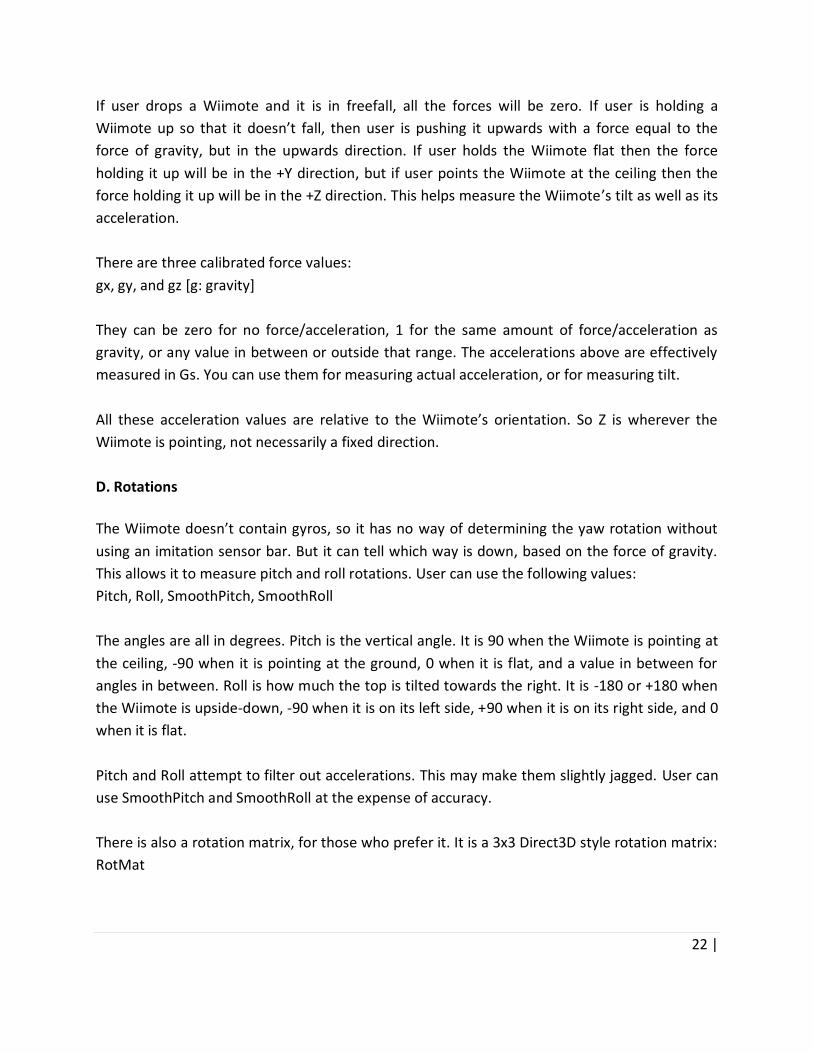
If user drops a Wiimote and it is in freefall, all the forces will be zero. If user is holding a
Wiimote up so that it doesn’t fall, then user is pushing it upwards with a force equal to the
force of gravity, but in the upwards direction. If user holds the Wiimote flat then the force
holding it up will be in the +Y direction, but if user points the Wiimote at the ceiling then the
force holding it up will be in the +Z direction. This helps measure the Wiimote’s tilt as well as its
acceleration.
There are three calibrated force values:
gx, gy, and gz [g: gravity]
They can be zero for no force/acceleration, 1 for the same amount of force/acceleration as
gravity, or any value in between or outside that range. The accelerations above are effectively
measured in Gs. You can use them for measuring actual acceleration, or for measuring tilt.
All these acceleration values are relative to the Wiimote’s orientation. So Z is wherever the
Wiimote is pointing, not necessarily a fixed direction.
D. Rotations
The Wiimote doesn’t contain gyros, so it has no way of determining the yaw rotation without
using an imitation sensor bar. But it can tell which way is down, based on the force of gravity.
This allows it to measure pitch and roll rotations. User can use the following values:
Pitch, Roll, SmoothPitch, SmoothRoll
The angles are all in degrees. Pitch is the vertical angle. It is 90 when the Wiimote is pointing at
the ceiling, -90 when it is pointing at the ground, 0 when it is flat, and a value in between for
angles in between. Roll is how much the top is tilted towards the right. It is -180 or +180 when
the Wiimote is upside-down, -90 when it is on its left side, +90 when it is on its right side, and 0
when it is flat.
Pitch and Roll attempt to filter out accelerations. This may make them slightly jagged. User can
use SmoothPitch and SmoothRoll at the expense of accuracy.
There is also a rotation matrix, for those who prefer it. It is a 3x3 Direct3D style rotation matrix:
RotMat

23 |
E. Sensor Bar
The sensor bar is a bunch of Infra Red lights which are always on. User can make fake sensor
bar with candles, Christmas tree lights, or Infra-Red remote controls with a button held down.
Further user can read the position of the infra-red dots that the Wiimote can see with:
wiimote.dot1x, wiimote.dot1y
…
wiimote.dot4x, wiimote.dot4y
F. LEDs
The four LEDs of Wiimote can be controlled simultaneously with “Wiimote.Leds”, which takes a
value between 0 and 15. Or user can set: Wiimote.Led1, Wiimote.Led2, Wiimote.Led3, and
Wiimote.Led4, to either true or false individually.
G. Force Feedback
User can activate force feedback by setting: “Wiimote.Rumble” to either true or false. This
makes Wii-Mote vibrate, thus emulating a feedback.
H. Speaker
Variables “Wiimote.frequency” and “Wiimote.volume” can be used to control the Wiimote
speakers. User can also turn the speaker on and off by setting either of these values:
Wiimote.Speaker = true/false, or Wiimote.Mute = true/false can be used to turn the speakers
on/off, or mute/unmute them.
I. Multiple Wiimotes
Wiimote.Count stores the number of Wiimote currently connected to GlovePIE. User can
access a particular Wiimote by putting a number after the word “Wiimote” and before the dot.
For example:
Enter = wiimote2.A
Wiimote.Exists can be used to figure whether connection to particular Wiimote is active.

24 |
In summary GlovePIE can be used as a scripting platform to control Wiimote, or to pass the
Wiimote gestures or buttons to program running on the same machine running GlovePIE.
Extension to such system can be attained by using internet to pass control signals from Wiimote
to remote devices through GlovePIE.
4.3 Blender: 4.3.1 History and concept: Blender was first conceived in December 1993 and born as a usable product in August 1994 as an integrated application that enables the creation of a broad range of 2D and 3D content. Blender provides a broad spectrum of modeling, texturing, lighting, animation and video post-processing functionality in one package. Through its open architecture, Blender provides cross-platform interoperability, extensibility, an incredibly small footprint, and a tightly integrated workflow. Blender is one of the most popular Open Source 3D graphics applications in the world. Aimed world-wide at media professionals and artists, Blender can be used to create 3D visualizations, stills as well as broadcast and cinema quality videos, while the incorporation of a real-time 3D engine allows for the creation of 3D interactive content for stand-alone playback. Originally developed by the company 'Not a Number' (NaN), Blender now is continued as 'Free Software', with the source code available under the GNU GPL license. It now continues development by the Blender Foundation in the Netherlands. Key Features of Blender Include:
Fully integrated creation suite, offering a broad range of essential tools for the creation of 3D content, including modeling, uv-mapping, texturing, rigging, skinning, animation, particle and other simulation, scripting, rendering, compositing, post-production, and game creation;
Cross platform, with OpenGL uniform GUI on all platforms, ready to use for all versions of Windows (98, NT, 2000, XP), Linux, OS X, FreeBSD, Irix, Sun and numerous other operating systems;
High quality 3D architecture enabling fast and efficient creation work-flow;
More than 200,000 downloads of each release (users) worldwide;
User community support by forums for questions, answers, and critique at http://BlenderArtists.org and news services at http://BlenderNation.com;
Small executable size, easy distribution;
4.3.2 Blender Interface: The concepts behind Blender's interface are specifically designed for a graphics modeling application and the vast array of features are different and differently grouped from other 3D
25 |
software packages. In particular, Windows users will need to get used to the different way that Blender handles controls such as button choices and mouse movements. Some blender features are familiar, like the top menu bar of "File", "Add"..."Help". However, many other features are quite unheard of in most (if not all) other applications. For example:
Blender windows cannot overlap and hide each other, one exception being a small number of mini-floating panels which are transparent, fold-able, small, and dock-able.
Blender relies heavily on keyboard shortcuts to speed up the work.
Blender's interface is entirely drawn in OpenGL and every window can be panned, zoomed in/out, and its content moved around.
User’s screen can be organized exactly to his/her taste for each specialized task and this organization can be named and memorized.
These key differences make Blender a unique, powerful, and very nimble application. The user interface is the vehicle for two-way interaction between the user and the program. The user communicates with the program via the keyboard and the mouse, and the program gives feedback via the windowing system. The interface can be broken down into several key areas: Windows, Contexts, Panels, and Buttons (controls). For example, The “Button window” contains Context buttons which show different groups of Panels and the Panels each show groups of Buttons.
4.3.3. Keyboard and mouse Blender can be operated by conventional keyboard/mouse interface, and can also be extended to support non-standard input devices. Following section outlines how blender can be used to create and manipulate a simple 3D view. Blender's interface is designed to be best used with a three-button mouse. A mouse wheel is quite useful, but not essential. Because Blender makes such extensive use of both mouse and keyboard, a golden rule has evolved among Blender users: Keep one hand on the mouse and the other on the keyboard. The most frequently used keys are grouped so that they can be reached by the left hand in standard position (index finger on F) on the English keyboard layout.
26 |
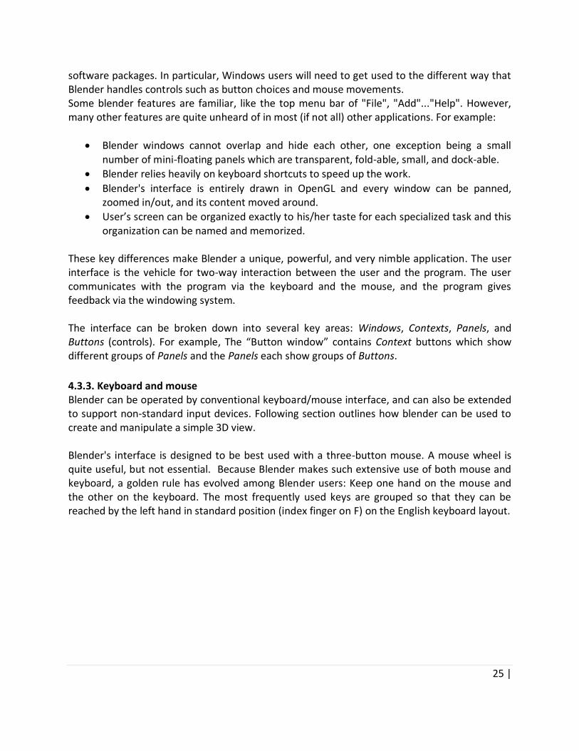
4.3.4. Blender UI: The Basics:
Figure 3 - Initial Blender Screen
Fig xx demonstrates the Blender UI:
The main menu panel is located at the top of the screen.
The main 3D view is shown as area with a grid overlaid. It shows the current scene from the top.
The menu for the 3D view is located below it.
At the bottom of the screen is the “Buttons panel”. Fix xx demonstrates a simple object, which can be manipulated in different ways in blender. The fix shows:
A cube - the square in the middle. This is selected, indicated by both having a pink outline and by having a 3D Transform manipulator (the arrows that user can drag to manipulate the object).
A light - the small round object, with dashed line.
And a camera - clipped to the bottom of the screen.

27 |
Interacting with the 3D scene
Figure 4 - Rotate Objects in Blender
Holding down the middle mouse button and dragging will rotate the cube. Figure above shows the rotated cube, until one is looking at the cube from a top. Changing the 3D scene to Perspective mode
Figure 5 - Orthographic Mode

28 |
This current view is known as an orthographic view. It can be easier to view a scene in perspective mode, which takes into account depth.
Figure 6 - Perspective Mode
To change into perspective, user can select View -> Perspective option from the 3D View menu.
Figure 7 - Change Mode in Blender
29 |
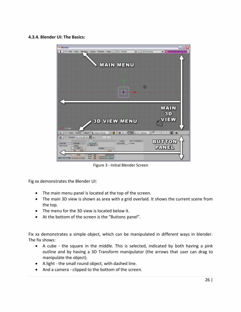
Manipulating objects within the scene
User will be able to move objects around by clicking and dragging the handles on the 3D Transform manipulator. The move, rotate and scale 3D manipulators are shown below, along with a combo 3D manipulator that includes all three.
Translate
Rotate
Scale
Combo
Figure Transformation with object To change the 3D manipulator type, user can click on the icons shown next in the 3D View menu.

30 |
Figure 8 - Manipulator Icons
Select manipulator icons.
Figure 9 - Manipulator Selection Menu
Another quick way to change the 3D manipulator type is to press Ctrl Space and select Translate, Rotate and Scale from the menu. Selecting other objects within the scene
31 |
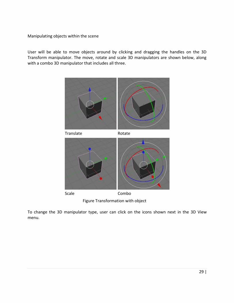
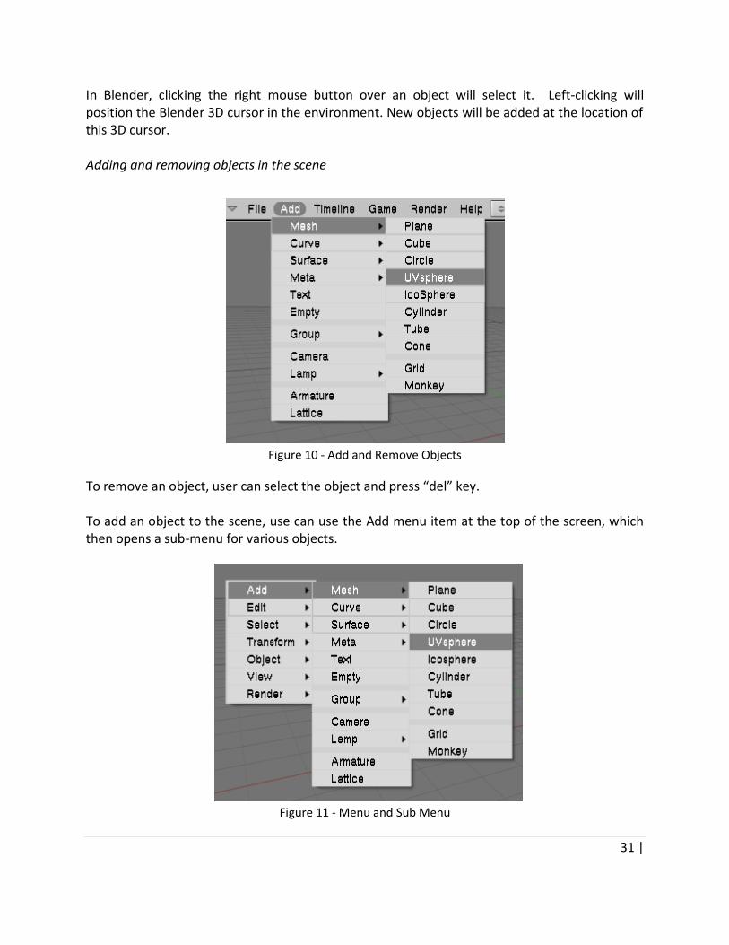
In Blender, clicking the right mouse button over an object will select it. Left-clicking will position the Blender 3D cursor in the environment. New objects will be added at the location of this 3D cursor. Adding and removing objects in the scene
Figure 10 - Add and Remove Objects
To remove an object, user can select the object and press “del” key. To add an object to the scene, use can use the Add menu item at the top of the screen, which then opens a sub-menu for various objects.
Figure 11 - Menu and Sub Menu

32 |
User can also press the Space key within the 3D view to display a menu with a number of useful functions, including the Add menu. This will then allow user to add a number of simple (or primitive) models to the scene, including planes, cubes, spheres and cylinders. User can also add Suzanne, a model of a monkey head. Fixing newly added 3D objects
Figure 12 - Newly Added Objects
The animated image shows a cube newly placed into the scene, and the steps required to have
it placed in the scene as expected.
When user adds a new object, Blender will do two things.
The new object will automatically be placed in Edit mode. Extensive editing of object meshes is outside the scope of this article, so for now user will need to press the Tab key to toggle off Edit mode and return to Object mode, every time user adds a new object into the scene.
The new object will initially be rotated as orientated to the current view. Renaming objects When user adds a new object, Blender will assign it a default name (e.g. Cube, or Cube.001 if Cube already exists). Generally it’s considered a good practice to rename objects using more relevant terms, such as player, crate, pickup, etc... This will make the view/scene a lot more readable when it gets more complex, as well as making it more readable for other people viewing it.

33 |
To rename an object, user can select the Object panel, and change the name within the OB: area.
Figure 13 - Editing Panel
Editing panel also allows for renaming of objects. 4.4 Integrated Pro-MOTE System: Pro-MOTE system integrates these three technologies, the Wii-Mote, GlovePIE and Blender to create a 3-D virtual platform, which can be used as a 3-D whiteboard. The interface between Wii-MOTE and blender is defined in two parts. A. Mouse Emulation As explained in the previous section, blender menu can be controlled to create, edit, move,
rotate and in general manipulate several 3-D objects. Further Wiimote, in combination with
GlovePIE can be used to emulate mouse operation. An integrated system thus allows a user to
create and manipulate 3-D objects in blender environment.
Moreover certain key-mappings in this implementation allows for short-cuts for certain
functions in Blender. For example, button-A of Wiimote corresponds to the pop-up menu in
Blender, and then the arrow keys can be used to browse various operations from the tool-
menu. Button-S in Wiimote is set as a shortcut to “scale”, R for “rotate” and G for “Grab” in
Blender.
B. FreeHand Drawing Second part of the Pro-MOTE interface is to use hand gestures to draw arbitrary image in 3D space. When in the free draw mode, pressing “R” button makes the Pro-MOTE go in free-draw mode. Any arbitrary movement is registered in Blender as a 3D movement. Combination of freehand drawing and Blender menu based operations can then be used to create arbitrary objects in a virtual 3D space.

34 |
5. Experimentation
5.1 Lab Experimentation:
Before the real world deployment and usage of the Pro-MOTE, a series of lab experiments were performed on the prototype system. Focus and intention of the experiments was to demonstrate the usability model of pro-MOTE.
Experimental setup was carried out with following steps: A. Wiimote setup: Communication channel between Wiimote and GlovePIE running on a Windows machine was setup by the use of “Bluesoleil” Bluetooth stack. Wiimote was made accessible to the GlovePIE by pressing “1+2” on Wiimote simultaneously. A simple script to control the LEDs of Wiimote demonstrated the successful connection. B. Mouse emulation: Using another GlovePIE script, Wiimote then was made to work as a mouse for the windows machine. The script also provides for calibration of individual Wiimote movements. Once the script is activated in GlovePIE, Wiimote movements were seen to track the mouse pointer on the windows machine accordingly. Left Mouse button and Right Mouse button were mapped to the R1/R2 button of Wiimote respectively.
C. Blender control: Now blender is run on the windows system running GlovePIE. Using the Wiimote as mouse, blender pull-down menus are shown to be controlled with gestures and R1/R2 buttons. Using these menus certain objects were shown to be created and edited. For the ease of operation certain commonly used features such as rotation were mapped to the Wiimote keys, using another GlovePIE scripts. D. Freehand Drawing: In addition to controlling blender menus to create 3-D objects, Pro-MOTE is also configured to create objects using free-hand drawing. With a GlovePIE script, and a freehand drawing board on the blender, Wiimote was shown to be used as a virtual pen to draw freehand images in 3-D view. These experiments demonstrated the usage model of Pro-MOTE system in lab environment.
35 |
5.2 Human Ethics approval: Since Pro-MOTE deals with human machine interface, Law requires us to obtain Human Ethics approval for real world experiments. We have already acquired the Ethics approval to conduct such experiments. These experiments will be conducted using a video conferencing platform (Access GRID) between geographically separated teams of scientists. Participants will be given a questionnaire to assess the quality of the 3D whiteboard system in comparison to the traditional methods. This experiment will be recorded, either by digital camera or by capturing the screen during the experiment. In either case, both the screen and the participant will be recorded. The tools that are going to be used for this experiment are either traditional design tools such as pen and paper or electronic tools such as 3D sketchpad or a virtual reality system that consists of a sensor jacket, cyber gloves, a 3D head mounted display and Wiimote. Stereoscopic devices may cause eye-strain. VR systems are known to induce motion-sickness and may trigger epileptic seizures. The likelihood is minimal in this study. However, participant CANNOT participate if they are sensitive to motion sickness OR if they ever had an epileptic seizure. A verbal warning will be given prior commencing the study. At the beginning of the experiment, participants will be given a fifteen-minute tutorial on the purpose of the experiment and how to use the necessary applications, during which time participants will be introduced to the system. They are free to ask any questions if they may have about the experiment or about the system. The design process will then continue for 15 minutes which will lead to a half an hour discussion time. The total time commitment involved is estimated to be 1 hour. Participant will be paid with a rate of 30AUD/hour for this experiment. All material, including the survey and video recordings will be kept strictly confidential and will not be made available to any persons outside this project. The researchers have no material interest in the outcome of this experiment. The results will be presented at departmental research seminars, peer-reviewed Australian and International conferences and via peer-reviewed journal articles. Participants can obtain feedback regarding the results of the project from the Interactive Systems and Virtual Reality Research Group website located at http://www.ics.mq.edu.au/~isvr/.

36 |
6. Conclusion and Future work
Collaboration expedites solutions, reduces re-invention, reaches beyond the boundaries of
individual knowledge and finally helps innovations. Problem solving is often accelerated with
involvement of multiple people with relevant expertise. However, it is not always possible to
gather all the relevant people in the same room. Distant communication, therefore assume a
significant importance for collaborative work.
Communication technologies relevant to scientists and collaborators can be broadly categorized as text based, voice based, voice and video based, and shared platform based. While the conventional text/voice/video based technologies form the base of communication, there remains a scope for development of real time editable collaborative platforms. Pro-MOTE 3D whiteboard system is such an interactive multi-user editable platform, which is intended to be used for scientific collaborations. With Pro-MOTE multiple users can simultaneously view, create, edit, and manipulate multiple 3D objects. Using this system, scientists can communicate in terms of flow charts, system diagrams, and other complex 3D objects, which are otherwise difficult to explain through conventional communication systems such as tele-conference or video-conference, or 2-D whiteboards. Our research included studying methods for hand gesture recognition, while identifying their advantages and shortcomings in the context of Pro-MOTE. We also studied various systems and platforms which can be used to model and interpret these gestures. Further, we looked into some of the systems available for 3-D editing and viewing. In the end we decided to use Wiimote, GlovePIE and blender for the implementation of Pro-MOTE. Use of Wiimote for gesture capture ensures intuitive drawing of objects in virtual 3D environment. Use of GlovePIE allows the system of be easily extended to support more features, and different 3-D environment. Blender works as a 3-D platform for editing and viewing in this system. Using this system as a precursor, we plan to support more shapes and objects to be defined on this platform for more enhanced collaboration between users. We also consider the addition of newly developed technologies such as Nvidia 3-D-vision [Nvidia Corporation, 2009] to allow rendered images to be viewed in the 3D whiteboard system.

37 |
References
Analog Devices. 2009. Accelerometer Design and Applications. [Online] Available at: http://www.analog.com/en/technical-library/faqs/design-center/faqs/CU_faq_MEMs/resources/fca.html [Accessed 5 May 2009] Baudel, T. and Beaudouin-Lafon, M. 1993. CHARADE: Remote Control of Objects using Free-Hand Gestures. Communications of the ACM, 36(7),pp.28-35. Cootes, T.F. et al. 1995. Active Shape Models – Their Training and Applications. Computer Vision and Image Understanding , 61(2). Costanza E., Inverso S.A., and Allen R. 2005. Toward subtle intimate interfaces for mobile devices using an EMG controller. In Proceedings of the SIGCHI conference on Human factors in computing systems, Portland, Oregon, USA, April 02-07, pp. 481-489. Dabbleboard Corporation. (2009). Retrieved from Dabbleboard Corporation Web site: www.dabbleboard.com. [Accessed 5 May 2009] Edadi, Y. M., & Utterback, J. M. 1984. The Effects of Communication on Technological Innovation. Management Science, 30, pp.572-585. Fels, S. 1994. Glove-TalkII: Mapping Hand Gestures to Speech Using Neural Networks – An Approach to Building Adaptive Interfaces. Ph.D. dissertation, University of Toronto,Canada. Gao, Y., and Kavakli, M. 2006. VS: Facial Sculpting in the Virtual World. Pages 35-35 in Computational Intelligence for Modeling, Control and Automation. Sydney, NSW, Australia. 28 Nov - 1 Dec 2006. GlovePIE Software and its usage. Available at: http://carl.kenner.googlepages.com/glovepie [Accessed 1 May 2009] Hara, H. Solomon, P. Kim, S. and Sonnenwald, D. 2003. An Emerging View of Scientific Collaboration. Journal American Society for Information and Technology. 54(10), pp.952-965.
Hasanuzzaman, M. and et al. 2004. Real-time Vision-based Gesture Recognition for Human Robot Interaction. Robotics and Biomimetics, 2004. ROBIO 2004. IEEE International Conference on: Shenyang, pp 413-418.
38 |
Johnston, W., 2000. Vision for Collaboratories and the DOE Science Grid. [Online]. Argonne. Available at: http://acs.lbl.gov/~johnston/Grids/DOE_Science_Grid+Collab_Grids.4up.pdf [Accessed 5 May 2009] Kawakli, M., 2008. Gesture recognition in virtual reality. Int. J. Arts and Technology, 1(2), pp215-229. Kendon, A. 1990. Conducting Interaction: Patterns of behavior in focused encounters. Cambridge University Press, Cambridge. Krueger, W. 1996. Artificial Reality II. Computing Section Technical Report No. 375, Addison-Wesley Publishing Company, New York. Kumo, et al. 1998. Vision-Based Human Interface System: Selectively Recognizing Intentional Hand Gestures. In Proceedings of the IASTED International Conference on Computer Graphics and Imaging, 219-223. Murakami, K., and Taguchi, H. 1991. Gesture Recognition Using Recurrent Neural Networks. Proceedings of the SIGCHI conference on Human factors in computing systems: Reaching
through technology, ACM Press, 237-242. McNeill, D. and Levy, E. 1982. Conceptual Representations in Language Activity and Gesture, pages 271-295. John Wiley and Sons Ltd. Meta Motion. 2009. Datagloves by 5DT. [Online] Available at: http://www.metamotion.com/hardware/motion-capture-hardware-gloves-Datagloves.htm [Accessed 5 May 2009]
Mine, M. 1997. Moving Objects in Space: Exploiting Proprioception in Virtual Environment Interaction. Proceedings of SIGGRAPH’97, ACM Press, pp.19-26. Mitra, S. and Acharya, T., 2007. Gesture Recognition: A Survey. IEEE Transactions on Systems, Man, and Cybernetics, 37(3), pp. 311-324. Nvidia 3D Vision, 2009, available at: http://www.nvidia.com/object/GeForce_3D_Vision_Main.html [Accessed 12 May, 2009] Open Cobalt Edusim edition. 2007. A new world on your SMARTBoard: Edusim 3D in your class. [Online] Available at: www.edusim3d.com. [Accessed 5 May 2009] Oskoei M. and Hu H. 2007. Myoelectric control systems—A survey. Biomedical Signal Processing and Control, 2(4), pp. 275-294.

39 |
Shrum, W., Genuth, J., & Chompalov, I. 2007. Structures of scientific collaboration. Cambridge, Mass:MIT Press. Sturman, D. J., and Zeltzer, D. 1994. A Survey of Glove-based Input. IEEE Computer Graphics and Applications, 14(1), pp 30-39. Starner, T., Pentland, A., and Weaver,J. 1998. Real-Time American Sign Language Recognition Using Desk and Wearable Computer Based Video. IEEE Transactions on Pattern Analysis and
Machine Intelligence. Washington, DC, USA, pp 1371-1375. Starner, T. and A. Pentland. 1996. Real-Time American Sign Language Recognition from Video Using Hidden Markov Models. In AAAI Fall Symposium on Disabilities. Cambridge, MA. Sturman, David J., and David Zeltzer. 1994. A Survey of Glove-based Input. IEEE Computer Graphics and Applications, 14(1), pp 30-39. Szilas, N., Barles, J. and Kavakli,M. 2007. An implementation of real-time 3D interactive drama, Computers in Entertainment. 5(1), 5. Thomas, D., and Sandin, D. 1997. Final Report to the National Endowment of the Arts. US NEA R60-34-163, University of Illinois at Chicago Circle, Chicago, Illinois. Unveiling the "Sixth Sense", game-changing wearable tech. 2009. [Video] Pattie Maes' lab at MIT. Utsumi, A. Et al. 1997. Direct Manipulation Scene Creation in 3D. SIGGRAPH’97 Electronic Garden. Waleed, K. 1995. GRASP: Recognition of Australian Sign Language Using Instrumented Gloves. Bachelor’s thesis, University of New South Wales. Zhang, X. et al. 2009. Hand Gesture Recognition and Virtual Game Control Based on 3D Accelerometer and EMG Sensors. International conference on Intelligent user interfaces. New
York, USA, pp 410-406.
40 |
Appendix - A
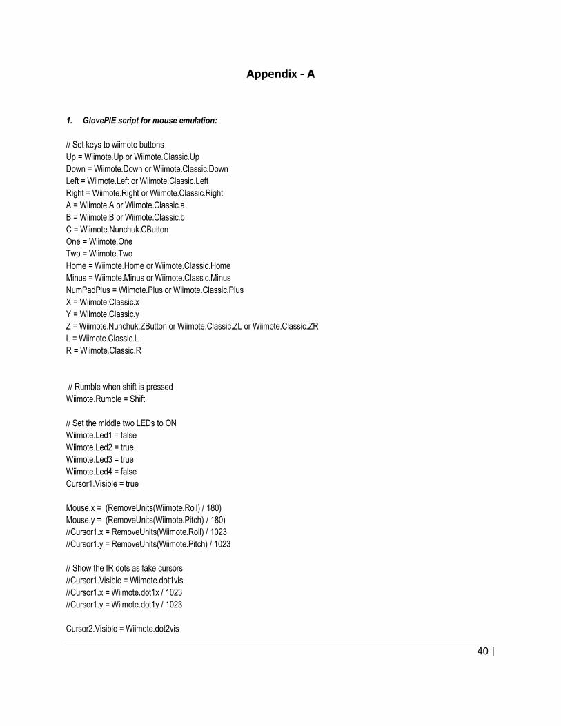
1. GlovePIE script for mouse emulation:
// Set keys to wiimote buttons
Up = Wiimote.Up or Wiimote.Classic.Up
Down = Wiimote.Down or Wiimote.Classic.Down
Left = Wiimote.Left or Wiimote.Classic.Left
Right = Wiimote.Right or Wiimote.Classic.Right
A = Wiimote.A or Wiimote.Classic.a
B = Wiimote.B or Wiimote.Classic.b
C = Wiimote.Nunchuk.CButton
One = Wiimote.One
Two = Wiimote.Two
Home = Wiimote.Home or Wiimote.Classic.Home
Minus = Wiimote.Minus or Wiimote.Classic.Minus
NumPadPlus = Wiimote.Plus or Wiimote.Classic.Plus
X = Wiimote.Classic.x
Y = Wiimote.Classic.y
Z = Wiimote.Nunchuk.ZButton or Wiimote.Classic.ZL or Wiimote.Classic.ZR
L = Wiimote.Classic.L
R = Wiimote.Classic.R
// Rumble when shift is pressed
Wiimote.Rumble = Shift
// Set the middle two LEDs to ON
Wiimote.Led1 = false
Wiimote.Led2 = true
Wiimote.Led3 = true
Wiimote.Led4 = false
Cursor1.Visible = true
Mouse.x = (RemoveUnits(Wiimote.Roll) / 180)
Mouse.y = (RemoveUnits(Wiimote.Pitch) / 180)
//Cursor1.x = RemoveUnits(Wiimote.Roll) / 1023
//Cursor1.y = RemoveUnits(Wiimote.Pitch) / 1023
// Show the IR dots as fake cursors
//Cursor1.Visible = Wiimote.dot1vis
//Cursor1.x = Wiimote.dot1x / 1023
//Cursor1.y = Wiimote.dot1y / 1023
Cursor2.Visible = Wiimote.dot2vis

41 |
Cursor2.x = Wiimote.dot2x / 1023
Cursor2.y = Wiimote.dot2y / 1023
Cursor3.Visible = Wiimote.dot3vis
Cursor3.x = Wiimote.dot3x / 1023
Cursor3.y = Wiimote.dot3y / 1023
Cursor4.Visible = Wiimote.dot4vis
Cursor4.x = Wiimote.dot4x / 1023
Cursor4.y = Wiimote.dot4y / 1023
// Show expansion and wiimote forces
debug = var.Expansion+'; Bat='+Wiimote.Battery+'; Pitch='+RemoveUnits(Wiimote.Pitch)+' Roll='+RemoveUnits(Wiimote.Roll)+';
'+Wiimote.RelAccX+', '+Wiimote.RelAccY+', '+Wiimote.RelAccZ