pro-150 digital motor controller - 4qd · 2016-04-16 · pro-150 digital motor controller ... in a...
TRANSCRIPT

www.4QD.co.uk Email to: [email protected]
“We're in Control”“We're in Control”
36 Greenfields
Earith
Cambridgeshire
PE28 3QH
Instruction Manual
Pro-150 Digital Motor ControllerMark 2
Software version 2.0
Keep this manual safe after installation in case a fault develops in your
system and you need to refer to the manual's fault finding information. The
latest version of this manual is always available from 4QD's www site.
The PRO 150 (PROgrammable 150 amp controller)
is the first of a new range of 4QD motor controllers
to benefit from digital technology.
The PRO 150 is a digital, four-quadrant motor
controller for battery operation of permanent magnet
DC motors. 4 Quadrant means that it controls speed
and direction, drive and braking.
The standard controller is suitable for 24v to 36v
batteries (14v through 42v operation). The 48v
version is suitable for battery voltages between 16V
and 48V.
The controller will not operate from 12v.
The Pro-150 can deliver a motor current of up to
150A for short periods and up to 60A continuously.
The Pro-150 is digital: it uses computer technology.
This gives two advantages:
1 controllers with the identical programming will
behave identically and reproducibly.
2 The controller is 'intelligent' and, at power-up
checks itself and its environment for faults: if it finds
a fault, it will not operate but will display a fault
code.
If all is correct, it then starts to operate and the
display (if fitted) will read the battery voltage.
When a display is not fitted, a sounder is present
which will give a coded series of pulses to indicate
the fault found. This can be particularly useful in, for
instance, diagnosing a problem over a telephone
The Pro-150 is probably the easiest controller to
program that exists.
Date printed: 27th January 2015
1 Introduction

Page 2 Pro-150 controller instructions
2 Contents
Section Page
1 Introduction 1
2 Contents 2
3 Safety 3
4 Dimensions and Mounting 4
4.1 Internal features, dimensions
and mounting of board version 5
4.2 Mounting: display 6
5 Wiring 7
5.1 Simple wiring diagram 7
5.2 Motor and battery connections 8
5.3 Control wiring 9
Input mode 10
Throttle Pot 10
Voltage following 10
Reverse switch 10
5.4 Auxiliary connector 11
5.5 Parking Brake 11
6 Operation 12
7 Altering the Performance 13
7.1 General 13
7.2 Programmable parameters 14
7.3 Programmer & display connection 14
7.4 Altering a parameter 15
Programming mode 15
Restore factory defaults 15
Software Issue Number 15
7.5 Programmable parameters 16
8 Service and Fault finding 19
8.1 Detected Faults 19
8.2 Fault Numbers and codes 20
8.3 Fault sound codes 22
8.4 Other faults 22
8.5 Fuses 22
9 Service 23
Returning a controller 23
Serial number 23
10 Specifications 24
More information and wiringOur web site www.4qd.co.uk contains more
information on this and other controllers. Anything
that is beyond the scope of these instructions is likely
to be found in the Information - Wiring
diagrams section of the www site.
This includes such details as:
radio control
double heading
Dos and Don'ts
Do
Disconnect the battery before doing anything
else to the system.
Discharge the board before handling it. The
main capacitors hold charge for a long time.
Discharge them by shorting M- to B- terminals.
Use a Pozidriv (not Philips) screwdriver for
any screws supplied.
Contact 4QD before returning a controller.
See page 23.
Read this manual enough to familiarise yourself
with its contents. You may need some of this later!
Do Not
Solder to the terminals. Soldered joints are not
reliable enough at high currents, and soldered
terminals won't fit our test jigs so are unserviceable.
Allow metal swarf or filings, water or dirt to
contaminate the board.

Page 3Pro-150 controller instructions
3 Safety
Electric motors and batteries are dangerous. Any
motor controller can only operate properly in a
properly designed and functioning environment.
The Pro-150 can deliver short-term currents in excess
of 150 amps. Batteries of the sort commonly used
can delivered a huge mount more current: faulty
wiring or components can therefore cause the
batteries, the motor and their wiring to be a potential
fire risk.
A digital controller performs checks on its wiring as
it is switched on, and also does certain checks 'on the
fly' during operation. These checks should catch
most faults (inside the controller, as well as outside)
but conditions of operation, programming and use are
outside our control and 4QD can accept no liability
for the results of any fault.
Suggestions for wiring etc are given in good faith
and will suit most customers. 4QD can however
accept no liability for the design of your particular
machine: it is up to the machine manufacturer to
make sure that the machine is safe under any and all
fault conditions.
Circuit breaker
Faults in the battery or motor wiring pose a fire risk,
as well as introducing the possibility of uncontrolled
operation. You should make sure your batteries have
adequate circuit breakers to disconnect them in the
event of such fault, or in he event of unforeseen
circumstances where the power must be
disconnected.
Mechanical braking
In a controller with regenerative braking, mechanical
brakes are hardly used. However, it is the battery that
is doing the actual braking, not the controller. Faults
in the battery or any of the power wiring can
therefore render regenerative braking inoperative.
Mechanical braking should then be fitted as a safety
precaution.
Mounting
The controller must be mounted so that water and
dirt cannot contaminate it. The metal base plate
must not be modified as this will produce metal
swarf Such contamination is likely to compromise
the controller's safety features and can make it
behave in an unsafe manner or even destroy it.
Such damage caused by contamination will not be
repaired under the guarantee.
If water or other contamination does enter the
controller you must disconnect the battery
immediately and clean or thoroughly dry out the
controller before re-connecting the battery.
The unboxed controller has no protection against
contamination, so should not be used in
environments where this is a possibility.
Metal swarf is the most dangerous kind of
contamination, therefore never cut drill file or work
metal in any way near to the controller or the motor
unless properly sealed. In particular, never modify
the base plate while it is attached to the controller!
The boxed controller, if properly mounted, has
reasonable protection against rain etc.
The unboxed controller (or without its cover) and the
display both have full battery voltage present on
them: take great care that no conducting object or
contamination touches them while the battery is
connected. This is particularly likely if you are
accessing them, for instance to alter the performance.
Handling
The capacitors in the Pro-150 can retain charge for a
long while after the battery is disconnected so
immediately after disconnecting the batteries turn on
the ignition for a few seconds to discharge them.

Page 4 Pro-150 controller instructions
4 Dimensions and Mounting
The dimensions of the controller's base plate are
shown below. It has two M5 tapped screw holes for
mounting: ideally it should be in thermal contact with
the machine's chassis which will then act as
additional heatsinking.
The controller may be mounted in any orientation.
However you should consider whether it is likely to
be subject to dust, dirt, oil or water during use and
mount it appropriately.
The best orientation is vertically with connections at
the bottom: this way is water splashes get onto leads
etc. they will simply run downwards away from the
controller. If water does splash onto the controller, it
will run down the heatsink and away harmlessly.
Otherwise mount with the heatsink at the bottom so
water cannot get onto the circuit board.
Allow plenty of space to install the controller and all
connecting wires, and mount so that the mounting
screws can be easily accessed.
Heat Sinking
During operation, depending on motor current, the
aluminium base plate of the controller can get hot.
For best sustained performance, mounting to an
external heatsink; something good at conducting heat
with a large surface area exposed to the air. This may
be the aluminium chassis of a vehicle, an aluminium
mounting plate, or any other good heatsink.
1.80" (46mm)
Ma
ch
ine
Ch
assis
50
mm
55
mm
121mm
18
1m
m76
mm
C LM
5 T
appe
dM
5 T
appe
d
tag end of circuit board

Page 5Pro-150 controller instructions
4.1 Internal features, dimensions and mounting of board version
The diagram below shown the controller without the
cover to identify the main features referred to in this
manual.
Mounting: and Heat Sinking
The aluminium block of the unboxed controller may
get hot and should be mounted in thermal contact
with a suitable heatsink if sustained high current is
required. For best results, heatsink compound should
be used between block and heatsink
The controller should be mounted by means of the
two M4 tapped holes in the metal block heatsink,
onto the chosen metal (preferably aluminium) plate.
This plate will act as an additional heatsink.
This mounting is shown in the bottom diagram.
Vehicle Chassis
Component side
Battery Negative(B-) Terminal
Motor Positive(M+) Terminal
Motor Negative(M-) Terminal
Battery Positive(B+) Terminal
3.1 (78mm)
3.9
5" (1
00.3
mm
)
Overall Height 1.7" (43.2mm)
Serial number
5.53" (140.3mm)
Control (C)Connector
1234
0.50" (12.7mm)
M4 Tapped
M4 Tapped
0.50" (12.7mm)
CL
Brake (B)Connector
View of board from component side
FEDCBA
Display (D)Connector
Aux/Program (A)Connector
Forward
Power
Reverse

Page 6 Pro-150 controller instructions
4.2 Display and Mounting
The display is supplied attached to the programmer,
as shown below.
Programmer and display may be separated at any
time - they will work separately, but it may be easier
to leave them joined and not finally mount them until
you have made any performance alterations you
require.
The controller will work without the display so you
may want to leave mounting this until later.
The display is used for four purposes: you should
consider all of these when deciding where to mount
the display:
1: In normal use, to show the battery voltage,so
you can check how far discharged they are.
2:: Adjusting the performance (see section 7)
you will need both display and programming
buttons.
3: In the event of a fault, the display will
indicate the likely nature of the problem.
4: During power up, the controller makes
system checks and shows progress on the display.
Many of these checks are too fast for a human to see!
The display connects to the controller via a 4 way
cable. See section 7.3 for connections.
The display requires a rectangular cut-out in your
panel, with two M3 clearance holes as shown above.
Supplied with the display is a red plastic bezel which
should be sandwiched between the panel and the
display as shown below.
If you apply a thin bead of silicone rubber behind
your panel before mounting the display you can
easily make this completely water tight.
Programmer
SEL + –
Panel
Screws
Bezel
Display board
NUMBER VALUE
CL
1.28"
1.0"
0.7
5"

Page 7Pro-150 controller instructions
30-9
0-0
2
PR
O-1
50
Mark
22
00
7
Permanentmagnetmotor
Speed control pot
Control box
Reverse switch
Ignition switch
Black
Green
Blue
Red
Black
Blue GreenBlue
Red
White
Yellow
Yellow
6 core cable
Fuse or circuit breaker
(optional)
Programmable 150 controller
Simple wiring diagram
Black
Yellow
Red
White
Red
Board viewed as mounted on heatsink
that the ignition switch function may beacheived by a removeable control box.
Note
Black
FEDCBA
FEDCBA
5.1 Simple wiring diagram
The diagram shows the simplest wiring for the Pro-
150. Wiring is covered in more detail in section 5.1.
Use of a reversing switch is optional: the controller
can be programmed to accept a -wig-wag-(centre
zero) pot. See section 7.5.
Display
Most installations will also include the display: this
is not necessary to operation, but as it gives a read-
out of battery fault and indicated the nature of any
fault that may be detected in the system (see section
8.1), its use is strongly advised.
Red and green of the 4 way display connector on the
controller board are effectively the same as ignition
and pot - so it is possible to wire a control panel
using these with only two extra wires for the signals.
BCM
4QD's BCM-524 or 748 can be used, connected
between white and green wires. However the voltage
here is fed via a diode so the BCM indication will be
slightly lower than standard.
Fuse or Circuit breaker
Although this is not necessary to the controller's
operation it will serve as a safety disconnect if
required and it will also help protect against some
possible faults - such as a short from motor to battery
negative, which could destroy the controller if a fuse
is not fitted. Controllers destroyed thus are generally
un-repairable. You have been warned!
For most applications a breaker of 60 amps is
adequate. A suitable circuit breaker is commonly
available from most automobile audio sellers.
5 Wiring
Page 8 Pro-150 controller instructions
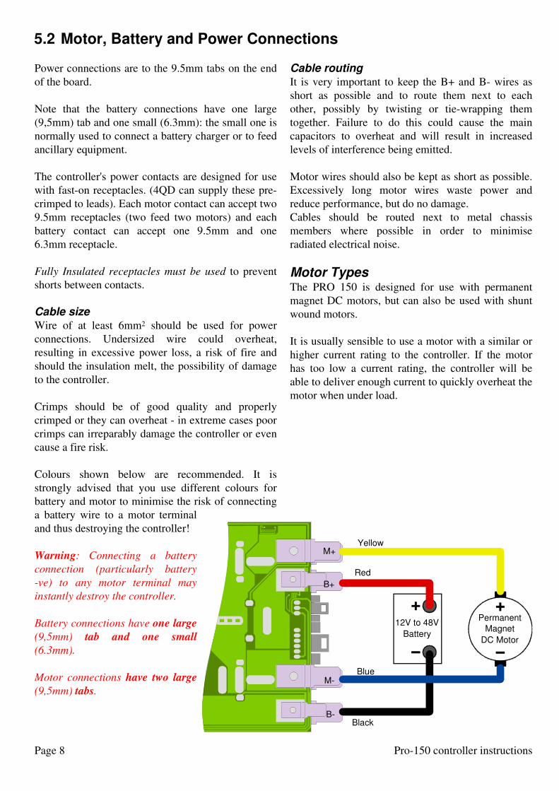
5.2 Motor, Battery and Power Connections
Power connections are to the 9.5mm tabs on the end
of the board.
Note that the battery connections have one large
(9,5mm) tab and one small (6.3mm): the small one is
normally used to connect a battery charger or to feed
ancillary equipment.
The controller's power contacts are designed for use
with fast-on receptacles. (4QD can supply these pre-
crimped to leads). Each motor contact can accept two
9.5mm receptacles (two feed two motors) and each
battery contact can accept one 9.5mm and one
6.3mm receptacle.
Fully Insulated receptacles must be used to prevent
shorts between contacts.
Cable size
Wire of at least 6mm2 should be used for power
connections. Undersized wire could overheat,
resulting in excessive power loss, a risk of fire and
should the insulation melt, the possibility of damage
to the controller.
Crimps should be of good quality and properly
crimped or they can overheat - in extreme cases poor
crimps can irreparably damage the controller or even
cause a fire risk.
Colours shown below are recommended. It is
strongly advised that you use different colours for
battery and motor to minimise the risk of connecting
a battery wire to a motor terminal
and thus destroying the controller!
Warning: Connecting a battery
connection (particularly battery
-ve) to any motor terminal may
instantly destroy the controller.
Battery connections have one large
(9,5mm) tab and one small
(6.3mm).
Motor connections have two large
(9,5mm) tabs.
Cable routing
It is very important to keep the B+ and B- wires as
short as possible and to route them next to each
other, possibly by twisting or tie-wrapping them
together. Failure to do this could cause the main
capacitors to overheat and will result in increased
levels of interference being emitted.
Motor wires should also be kept as short as possible.
Excessively long motor wires waste power and
reduce performance, but do no damage.
Cables should be routed next to metal chassis
members where possible in order to minimise
radiated electrical noise.
Motor TypesThe PRO 150 is designed for use with permanent
magnet DC motors, but can also be used with shunt
wound motors.
It is usually sensible to use a motor with a similar or
higher current rating to the controller. If the motor
has too low a current rating, the controller will be
able to deliver enough current to quickly overheat the
motor when under load.
Permanent
Magnet
DC Motor
B-
M-
B+
M+
12V to 48V
Battery
Black
Blue
Yellow
Red
+ +
− −
Page 9Pro-150 controller instructions
If the motor has a higher current rating than the
controller, the full torque output of the motor will not
be available, but the controller will not be damaged
since the motor current is automatically limited to a
safe value for the controller.
Remember that motors are generally rated in terms of
continuous current handling: for a typical motor short
term current (1 minute rating) may be 3 or 4 times as
much as continuous rating.
Use only good quality motors with brushgear and
commutator in good conditions: badly work brushes
and commutator can cause arcing (electrical noise)
which can cause controller failure. To minimise this
possibility it is desirable for the motor to to be fitted
with a suppression capacitor. If one is not present, a
10n 100V ceramic capacitor can be fitted between
brush pairs as close to the motor as possible.
Battery Type
The PRO 150 is designed for use with rechargeable
batteries of 18V to 48V nominal. The actual battery
voltage can be between 13V and 60V. This allows
plenty of room for droops or peaks in battery voltage
under heavy motoring or braking.
Be aware that the controller feeds current back to the
battery during braking, so if the battery is sensitive to
over-charging (such as Li-ion) think about what will
happen if regen braking is used when the battery is
fully charged.
A fully charged lead-acid 48v battery can normally
withstand the overcharging that can result when
regen braking dumps energy into it but under these
conditions the voltage may rise to 60v.
In nearly all cases, lead acid batteries will be used,
and these are indeed a very good choice.
There are two control connectors, the positions of
these are shown in the internal features diagram
(page 5). Most uses will only connect to the main 6
way connector which is accessible without removing
the controller's cover.
The Auxiliary connector allows some less common
controls to be fitted.
The mating connector supplied for both is suitable
only for the correct size of wire.
Acceptable wire sizes are:
7 stranded 0.22-0.25mm²
24 AWG (7/32 AWG)
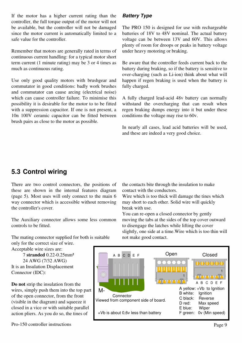
It is an Insulation Displacement
Connector (IDC):
Do not strip the insulation from the
wires, simply push them into the top part
of the open connector, from the front
(visible in the diagram) and squeeze it
closed in a vice or with suitable parallel
action pliers. As you do so, the tines of
the contacts bite through the insulation to make
contact with the conductors.
Wire which is too thick will damage the tines which
may short to each other. Solid wire will quickly
break with use.
You can re-open a closed connector by gently
moving the tabs at the sides of the top cover outward
to disengage the latches while lifting the cover
slightly, one side at a time.Wire which is too thin will
not make good contact.
5.3 Control wiring
A B C D E F ClosedOpen
D red: Max speedE blue: WiperF green: 0v (Min speed)
C black: Reverse
A yellow: +Vb to Ignition
+Vb is about 0,6v less than battery
B white: Ignition
1
1
A B C D E F
ConnectorViewed from component side of board.
M-
Page 10 Pro-150 controller instructions
Input mode
The controller can work in two modes, either single
ended (speed pot with separate switch for direction)
or Wig-Wag where the pot centre is zero speed. Pot
one way is forward and the other way is reverse.
Single ended is the default mode.
You can easily change to wig-wag either by
switching to a different mode (if a suitable one
exists) or by using the input learn feature, see
section 7.5 for altering the programming.
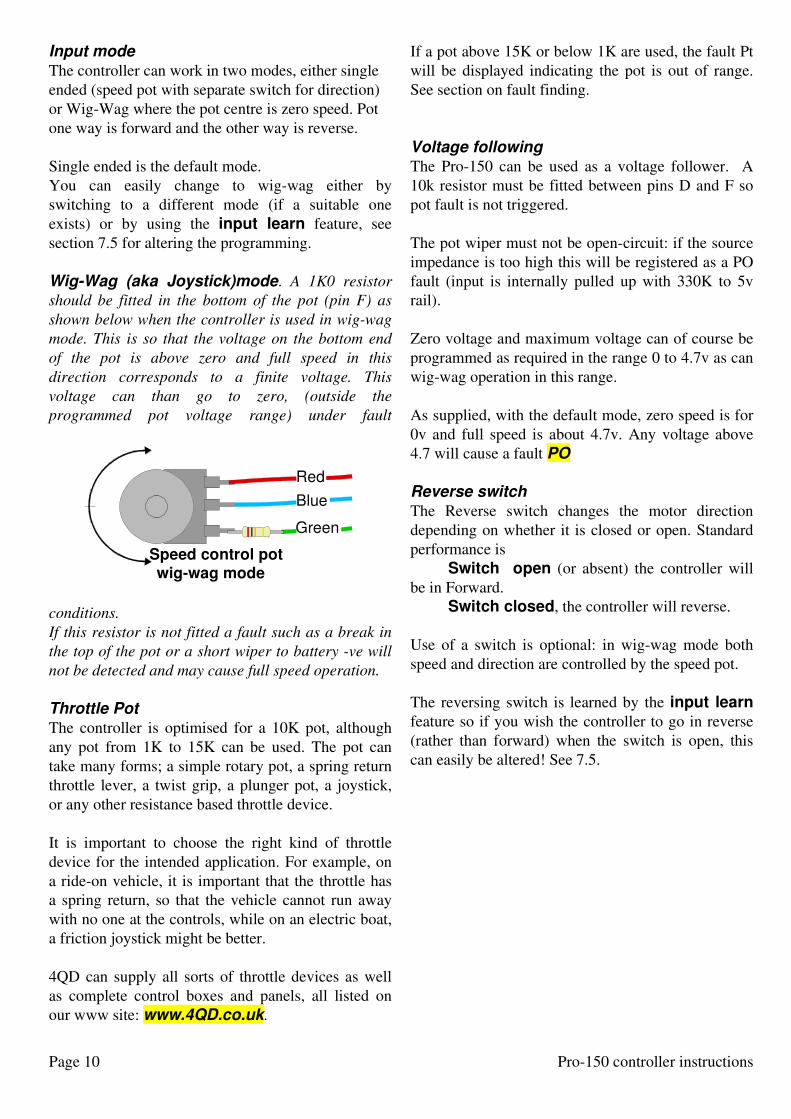
Wig-Wag (aka Joystick)mode. A 1K0 resistor
should be fitted in the bottom of the pot (pin F) as
shown below when the controller is used in wig-wag
mode. This is so that the voltage on the bottom end
of the pot is above zero and full speed in this
direction corresponds to a finite voltage. This
voltage can than go to zero, (outside the
programmed pot voltage range) under fault
conditions.
If this resistor is not fitted a fault such as a break in
the top of the pot or a short wiper to battery -ve will
not be detected and may cause full speed operation.
Throttle Pot
The controller is optimised for a 10K pot, although
any pot from 1K to 15K can be used. The pot can
take many forms; a simple rotary pot, a spring return
throttle lever, a twist grip, a plunger pot, a joystick,
or any other resistance based throttle device.
It is important to choose the right kind of throttle
device for the intended application. For example, on
a ride-on vehicle, it is important that the throttle has
a spring return, so that the vehicle cannot run away
with no one at the controls, while on an electric boat,
a friction joystick might be better.
4QD can supply all sorts of throttle devices as well
as complete control boxes and panels, all listed on
our www site: www.4QD.co.uk.
If a pot above 15K or below 1K are used, the fault Pt
will be displayed indicating the pot is out of range.
See section on fault finding.
Voltage following
The Pro-150 can be used as a voltage follower. A
10k resistor must be fitted between pins D and F so
pot fault is not triggered.
The pot wiper must not be open-circuit: if the source
impedance is too high this will be registered as a PO
fault (input is internally pulled up with 330K to 5v
rail).
Zero voltage and maximum voltage can of course be
programmed as required in the range 0 to 4.7v as can
wig-wag operation in this range.
As supplied, with the default mode, zero speed is for
0v and full speed is about 4.7v. Any voltage above
4.7 will cause a fault PO
Reverse switch
The Reverse switch changes the motor direction
depending on whether it is closed or open. Standard
performance is
Switch open (or absent) the controller will
be in Forward.
Switch closed, the controller will reverse.
Use of a switch is optional: in wig-wag mode both
speed and direction are controlled by the speed pot.
The reversing switch is learned by the input learn
feature so if you wish the controller to go in reverse
(rather than forward) when the switch is open, this
can easily be altered! See 7.5.
Speed control potwig-wag mode
Green
Blue
Red
Page 11Pro-150 controller instructions
5.4 Auxiliary connector
The Auxiliary/Programming connector (A),
inside the controller, has two functions. As
well as being the programmer connector, it can
be used for additional controls when the
programmer is not in use. Even if you are not
using this it is best to unplug the programmer
lead from the controller unless you are actually
using it.
Connections are identified in the diagram
right.
Slow / Fast
A fast /Slow switch can be fitted as shown. When
this is closed (pin A connected to Pin B) the
controller's top speed will be reduced to about half
full speed.
Inhibit
An inhibit switch may be fitted (inhibited when pin
C is shorted to pin A) : when this is closed, the
controller will not operate. Trip code 11 will be
displayed. When the inhibit is removed, the
controller's ignition must be switched off and on
again to reset it.
If Inhibit is activated during motion, the controller
will ramp down to zero speed and stop. It may thus
be used as an input for a motor overheat sensor.
This input may be used with a third connector in the
charger socket so that the controller cannot start up
when the charger is plugged in.
Slow
Fast
Inhibit
Go
Green
Blue
Red
FEDCBA
F SpareE SpareD Spare (SEL programmer)C Inhibit (+ programmer)B Slow (- programmer)A 0V (Internally connected to B-)
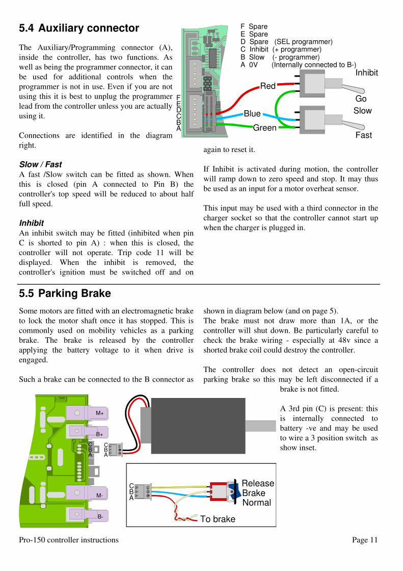
5.5 Parking Brake
Some motors are fitted with an electromagnetic brake
to lock the motor shaft once it has stopped. This is
commonly used on mobility vehicles as a parking
brake. The brake is released by the controller
applying the battery voltage to it when drive is
engaged.
Such a brake can be connected to the B connector as
shown in diagram below (and on page 5).
The brake must not draw more than 1A, or the
controller will shut down. Be particularly careful to
check the brake wiring - especially at 48v since a
shorted brake coil could destroy the controller.
The controller does not detect an open-circuit
parking brake so this may be left disconnected if a
brake is not fitted.
A 3rd pin (C) is present: this
is internally connected to
battery -ve and may be used
to wire a 3 position switch as
show inset.
B-
M-
B+
M+
A AB BC C
ABC
To brake
ReleaseBrakeNormal
1

Page 12 Pro-150 controller instructions
6 Operation
Switching On
When you turn on the ignition to start the controller
up. it performs a number of system safety checks.
During this period you may hear the three relays
clicking and the display may show a sequence - such
as C0, C1, C2, C3. C4, C5 - as it performs these
checks. However, this checking is so fast you
normally won't see it! If the display gets stuck on one
of these, there may be a problem and the display will
eventually show a fault number (see section 8.1) and
the sounder will beep a fault code.
If all is well, the display will finally show a steady
number which is a measurement of the battery
voltage. The controller is now ready to work.
If there is a problem with any of these safety checks,
the display will flash a fault number (or code), the
beeper will sound a code and the controller will not
operate.
Two most likely fault the controller may detect
during power-up is:
Pot (or pot wiring) fault
If the controller detects a fault here, it will display
Pt. See page 20.
High Pot Lock Out (HPLO)
If you do not have the speed pot at zero speed when
you switch on, the controller will not operate until
you turn the speed to zero.
If the controller detects the pot is not at zero speed, it
will display HL (and the sounder will sound a
continuous tone) until you turn the speed pot to zero.
Then the controller will display the battery voltage.
Flashing number
Other faults may of course occur and be detected. In
this case the number displayed will flash to indicate a
fault has been found.
More information on these can be found in section
8.1.
Operation
Initially, you will probably want to check out the
operation with the default 'mode'.
Once successful power-up has occurred, pot lockout
has disengaged, move the throttle to control the
speed. The further the throttle is moved, the higher
the speed will be.
If a reversing switch is used, operate the reverse
switch to choose the required motor direction.
Acceleration and deceleration rates are controlled
give a smooth throttle response.
If the throttle is moved quickly, the speed changes
smoothly at a rate depending on the ramp time
settings. The default acceleration is 4 seconds to full
forward speed, and 2 seconds to decelerate from full
forward speed to zero.
Different ramp rates apply in reverse, and full reverse
speed is normally half of full forward speed, You can
easily alter any of these rates and speeds, see section
7.2.
Dual Ramp reversing
If the machine is operating at full speed and you
change direction (probably by using the direction
switch) the controller will
1 decelerate to zero speed, (controlled by the
deceleration ramp rate)
2 pause for a fraction of a second
3 Accelerate (under control of the acceleration
ramp rate) to full speed in the opposite direction
This is therefore called 'dual ramp reversing' and is
the most useful performance in most applications.
Switching off
Turn the ignition switch off to shut the controller
down.
You will usually do this after the motor has stopped.
However, if the ignition switch is turned off while
the motor is running, the display flashes and the
controller will reduce the motor speed smoothly
down to zero before it shut itself down.

Page 13Pro-150 controller instructions
7 Altering the Performance
The Prog 150 is operated by a built-in 'micro-
computer'. This Micro can very easily be instructed
to alter the performance.
There are two features which the average user is
most likely to wish alter.
Mode. The micro has several different 'modes' built
in, to give performance matched to, for instance, a
golf buggy, or a miniature loco.
It may easily be switched from one mode to another.
Input Learn:
the standard 'default' performance is optimised for a
10K pot with a switch for direction (as shown in the
wiring on page 7). However, if you are using a
different value pot, or wish to use a wig-way input,
or some other combination, or wish to use a voltage
input - the controller can be easily taught what
control system you are using.
Programming method.
This is a brief introduction: full instructions are given
in section 7.4
Programming is done via the 3 button programmer
which is supplies attached to the display.
Programming is started by turning on the ignition
with the SEL button depressed.
The display will indicate 00. to show it is in
programming mode.
The number displayed now is the number of the
parameter you wish to alter. You can increase and
decrease it with + and - buttons.
Be aware of the difference between the number of
the parameter you are about to alter and the actual
value of that parameter. When choosing a parameter
number, the RH decimal point will flash very slowly
indicating that you are not changing anything yet, but
are simply choosing what to change.
Whether choosing a parameter to alter, or changing
the value of that parameter, the + and - buttons will
increment the number displayed.
Parameter number
When the right decimal point is flashing, the + and -
buttons will alter the display to show the parameter
numbers. There are 15 user-adjustable parameters,
00-14.
If the display is incremented above 15 it shows PG.
Pressing SEL when PG is showing causes the
microcomputer to remember the new values.
When you reach the number of the parameter you
wish to alter, press SEL and the display will change
to indicate the current value of that parameter. The
+/- buttons will alter the display so you can select a
new value.
Once the display shows the new value you want,
press SEL again to accept this value and you will be
returned to Parameter number mode so you can
alter another parameter. So pressing SEL twice
without touching +/- will simply show you the
current value of that parameter.
If you switch the ignition off during programming,
all your changes will be forgotten. This is handy
should you have second thoughts and decide to abort
the changes.
Warning
After altering anything take care to check that you
have altered what you expected: it may be best to
chock the machine up so its wheels are free and it
will not move, so you can check you did exactly
what you wanted to.
Neither the controller nor 4QD can be responsible
for you instructing it to do something which may not
be safe in your machine! Or if you do not properly
understand what you are doing!
Be aware that the values you chose for any
parameter will only effect the current mode. So if
you are using mode 03 (locomotive) and alter, for
instance, the maximum reverse speed, you will not
affect the reverse speed in any other mode.
7.1 General

Page 14 Pro-150 controller instructions
7.2 Programmable parameters
The following parameters can be altered:
No. Definition Values Default Comments
00. Change mode Number 00. - 10. See page 16
01. Forward Acceleration Ramp Time 0.1—9.9 Sec 4.0 Seconds, adjustable in deciSeconds,
02. Forward Deceleration Ramp Time 0.1—9.9 Sec 2.0 Seconds, adjustable in deciSeconds,
03. Max Forward Speed 00—99 % 99 in 1% increments
04. Reverse Acceleration Ramp Time 0.1—9.9 Sec 4.0 Seconds, adjustable in deciSeconds
05. Reverse Deceleration Ramp Time 0.1—9.9 Sec 2.0 Seconds, adjustable in deciSeconds
06. Max Reverse Speed 00—99 % 50 in 1% increments
07. Throttle Dead band 0-10 % 5%
08. Parking Brake Delay 0.1-9.9 Sec 1 sec
09. Brake threshold 0—10% 1%
10. High Pot Lockout 0—99% 2%
11. Reverse Beeper Yes/No Yes
12. Pot / direction max speed forward 00-99 Measures pot
13. Pot zero 00-99 Measures pot
14. Pot / direction max speed reverse 00-99 Measures pot
PG Accept new programmed values
View of board from component side
Programmer
Display
red
yellowblue
greenspare
red
sparespare
yellowblue
green
SEL + –
1 red
yellowblue
greenspare
red = SEL
sparespare
blue = + or Inhibityellow = - or Slowgreen = 0v
red = power (as battery)
blue = datayellow = clockgreen = 0v
red
yellowblue
green
1
7.3 Programmer and display connection

Page 15Pro-150 controller instructions
Plug in the controls you propose to use (see section
5.1), the programmer and the display (if not already
in use).
Programmer and display connect as shown in the
diagram opposite (leads are shown shortened for
clarity). It does not matter if the programmer has
been separated from the display.
The ignition must be off initially. Connect a battery
or suitable power supply. The display will also be
off. What happens now depends on which of the
programmer buttons is depressed while you turn on
the ignition. Release the button as soon as the display
registers.
Programming mode
SEL The controller will enter programming mode
Restore Factory Defaults
+ Fd will be displayed for a few seconds.
Releasing + while Fd is displayed will cause the
factory default parameters to be restored. Holding +
down will show fault 11 (Inhibit activated). Useful if
you have been altering parameters and want to forget
your alterations.
Software Issue
- The controller will display a number which is
the software version number.
Entering Programming mode 1 Press and hold down the SEL button on the
programmer while you turn on the ignition.
The controller will switch on in programming mode.
To indicate this the display shows 00. with the
decimal point flashing slowly. You are now
programming!
You are most likely to want to change parameter 00
(mode number).
Any other parameters you alter will only affect the
mode that is active when you change them.
If you do want to change the mode, skip step 2 and
go to step 3
2 Use the + and - buttons to change the
number displayed to that of the parameter you
want to alter. See table opposite for a list of
changeable parameters.
3 Press SEL to tell the micro this is the
number of the parameter you wish to alter:
the display will change to show the present
Value of this parameter.
4 Use the + and - button to increase or
decrease the number on the display to the new
value you wish to use. Each press will increment
the number by one step.
Keep your finger on a button and the display will
change automatically, speeding up as it goes.
Remove your finger when you get near the
required value, and use individual presses to get
it exact.
5 Press SEL to accept the new value and
return to Parameter Number mode.
If you wish to alter another parameter, use SEL
again (step 2). Otherwise proceed:
6 Once all parameters have been altered as you
want, increment the parameter to PG (after
parameter 14) and press SEL.
There will be a short pause as the new values are
stored. Then the controller will go through its
normal power-up routine (see section 6).
The new values you entered were accepted and
stored in the mode number you used when you
started changing them.
If you turn off the ignition at any time during
programming, the changes will not be remembered:
this is a way of cancelling your changes should you
change your mind!
Remember you can always reset the controller to the
factory default by turning on the ignition with + held
down.
7.4 Altering a parameter
Repeat as r
equired
Page 16 Pro-150 controller instructions
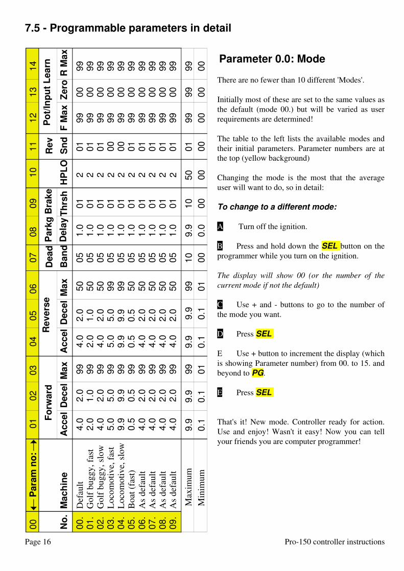
Parameter 0.0: Mode
There are no fewer than 10 different 'Modes'.
Initially most of these are set to the same values as
the default (mode 00.) but will be varied as user
requirements are determined!
The table to the left lists the available modes and
their initial parameters. Parameter numbers are at
the top (yellow background)
Changing the mode is the most that the average
user will want to do, so in detail:
To change to a different mode:
A Turn off the ignition.
B Press and hold down the SEL button on the
programmer while you turn on the ignition.
The display will show 00 (or the number of the
current mode if not the default)
C Use + and - buttons to go to the number of
the mode you want.
D Press SEL
E Use + button to increment the display (which
is showing Parameter number) from 00. to 15. and
beyond to PG.
E Press SEL
That's it! New mode. Controller ready for action.
Use and enjoy! Wasn't it easy! Now you can tell
your friends you are computer programmer!
Ma
ch
ine
Def
ault
Go
lf b
ug
gy
, fa
st
Go
lf b
ug
gy
, sl
ow
Lo
com
oti
ve,
fas
t
Lo
com
oti
ve,
slo
w
Bo
at (
fast
)
As
def
ault
As
def
ault
As
def
ault
As
def
ault
No
.
00
.01
.02
.03
.04
.05
.06
.07
.08
.09
.
Acc
el
Acc
el
Dec
el
Dec
el
Ma
xM
ax
Fo
rward
Rev
ers
e
2.0
1.0
2.0
5.0
9.9
0.5
2.0
2.0
2.0
2.0
Dea
d
Ban
dD
ela
yT
hrs
h
Park
g B
rak
e
HP
LO
Rev
Sn
d
Po
t/In
pu
t L
ea
rn
F M
ax
Zero
R M
ax
00
01
02
03
04
05
06
07
08
09
10
11
12
13
14
Para
m n
o:
4.0
4.0
4.0
4.0
4.0
2.0
4.0
5.0
9.9
0.5
2.0
1.0
2.0
5.0
9.9
0.5
2.0
2.0
2.0
2.0
4.0
4.0
4.0
4.0
4.0
2.0
4.0
5.0
9.9
0.5
50
50
50
99
99
50
50
50
50
50
05
05
05
05
05
05
05
05
05
05
1.0
1.0
1.0
1.0
1.0
1.0
1.0
1.0
1.0
1.0
01
01
01
01
01
01
01
01
01
01
2 2 2 2 2 2 2 2 2 2
99
99
99
99
99
99
99
99
99
99
00
00
00
00
00
00
00
00
00
00
99
99
99
99
99
99
99
99
99
99
0.1
0.1
0.1
0.1
9.9
9.9
9.9
9.9
9.9
01
01
99
99
99
99
99
Max
imu
m
Min
imu
m
10
10
50
00
00
00
01
00
00
00
00
0.0
99
99
99
99
99
99
99
99
99
99
00
00
01
01
01
01
01
01
01
01
7.5 - Programmable parameters in detail

Page 17Pro-150 controller instructions
Parameter 01 and 02:
Forward ramp times
These are the times for acceleration and deceleration
in forward drive. The display is in seconds, 0.1 sec to
9.9 seconds so the resolution is 1 deciSeconds (tenth
of a second).
Do not choose too fast (too small a number) an
acceleration or deceleration for your machine. If you
do, and it tips over when accelerating fast - don't
blame the controller (or 4QD!).
Fast acceleration and deceleration may also shorten
the operating life of the on-board relays.
Parameter 03: Max speed
This is the top speed. As you adjust this parameter
the display will show 00 - 99. This is the percentage
of available throttle electrical travel.
You can set this parameter in steps of 1% but low
value settings make no sense and will not work!
Generally, if your machine is too fast (so that you
need to reduce the top speed electrically) your gear
ratio is wrong.
Reducing top speed electrically causes the motor to
take more current. This can overload the controller
and the motor, so if your motor burns out (or the
controller overheats) - do not blame the controller!
Parameters 04, 05 and 06:
(reverse)
These are as parameters 01, 02 and 03, but for
reverse rather than forward.
Some machines, e.g. golf buggies, are unsafe to drive
fast in reverse, so different parameters are required.
Parameter 07: Dead band
This is most useful in joystick mode, where the
centre of movement of the joystick may have a
tendency to wander.
Default 5% of available throttle signal.
Parameter 08 and 09:
Parking brake.
These control the parking brake: ignore if your motor
does not have one fitted!
As the controller starts to apply power to the motor,
it applies power to the parking brake to release it.
Parameter 09 defines how much power is applied to
the motor before the brake is released.
Too low a value will allow the machine to roll back
on a hill start, too high a value and the motor will
start with a jerk.
As the motor stops, there is a short delay before the
brake power is removed (to allow the brake to re-
engage). Parameter 08 defines this delay. Typical
values will be 1/2 to 1 second.
Parameter 10: HPLO
If the controller's ignition is turned on with the pot
high (not at zero) the controller would start up
immediately. So a High Pot Lock Out (HPLO)
function is present.
Parameter 10 sets the pot level which is considered
high. The display will show 00-99 as the pot is
turned from dead band level to full speed. Zero
means the level is the same as the dead-band. 99 is
full pot input. If the pot is above this level at switch
on, HPLO will prevent operation until the pot is
turned low.
So if you set this to 99: there is effectively no HPLO.
If you set it to 10%, then any pot setting below 10%
at switch on will be accepted: this will probably
allow the machine to creep forward, which you may
deem desirable but it's up to you to chose a safe value
for your machine.
Generally choose a level of zero or only slightly
more.
Default (most modes) 2%.
Parameter 11: Reverse sounder
There is an on-board sounder which can be made to
bleep in reverse. This parameter tuns the function
on/off.

Page 18 Pro-150 controller instructions
Parameter 12, 13 and 14:
Pot / Input Learn
These all allow you to define how the speed pot and
direction switch affect the performance.
Select the parameter. Turn the pot (the display will
show 00-99 as you turn the pot, so finding the centre
of a wig-wag is easy!), set the direction switch
appropriately (if you are using one) and press SEL.
This indication of pot position allows you to measure
what the pot is doing which could be useful in a
factory making golf buggies, for setting up the speed
pedal zero!
It is always better to adjust the throttle pot
mechanism for correct 00-99 display on the
controller than to match the controller to a badly
adjusted throttle!
The controller is set as standard for 10K pot, will
accept 5K to 15K. However, changing the pot value
will affect slightly the speed range of the pot: these
parameters allow you to fine tune this.
You can also define whether reverse is with the
switch open or closed. Whether you want single
ended or wig-wag. If you are using a voltage input,
you can calibrate the controller to suit your input!
It is of course possible to tell the controller silly
things: if you do this and try to program (by going to
PG display), the controller will not accept the values.
If programming in wig-wag operation a 1k0 resistor
should be fitted in the bottom of the pot - see note on
page 10.
There may well be silly settings that the controller
does accept - so if you change anything it is up to
you to make sure it does what you want and is safe in
your machine!
You will normally have to adjust all three of these
parameters!
Parameter 12:
Maximum speed forward.
Adjust the pot (the display will change to show
where the pot is) and the direction switch (if you are
using one) to the position and state you require as full
speed forward. Press SEL
Parameter 13:
Zero speed.
Adjust pot to the zero speed position.
Leave the Direction switch in forward.
Press SEL
Parameter 14:
Max reverse (or zero speed).
If you are using single ended mode, simply adjust
the speed pot to zero, switch the direction switch to
reverse and press SEL
The controller will use the pot as a zero to full speed
input, with the switch for direction.
If you are using a wig-wag pot, adjust the pot to the
position you require to be maximum reverse speed
and press SEL
With a wig-wag pot, you will not, of course, be using
a direction switch.
Programming end
When you have finished programming, you need to
tell the controller "that's it - remember the new
values". Simply turning of the ignition switch will
cause the controller to forget the changes you have
made.
Adjust the Parameter number above 14: the display
will show PG.
If you have tried to re-program Pot Learn to values
which do not make sense, the controller will not
advance above 14!
Press SEL
The controller will remember the new values and go
through its start up routing, so it may well show a
fault such as HL (HPLO). Or if the pot is at zero, it
will display the battery voltage and the controller is
ready to go.

Page 19Pro-150 controller instructions
8 Service and Fault finding
The Pro-150 has sophisticated self and environment
testing so will find most faults that are likely. If such
a fault if detected, the controller will shuts down the
and will sound a pattern of beeps (see page 22) and
display an appropriate number to indicate the nature
of the fault found. The fault number will flash on and
off.
Most faults are caused by dud batteries, bad motors
or bad wiring. The controller cannot know exactly
what the problem is, but it will detect most such
faults and will respond correctly to them by not
working and by indicating a fault code.
If your controller doesn't work, you should check the
following points before contacting 4QD for
assistance.
Erratic fault displayIf noise (probably from the motor wiring) gets into
the display wiring the controller can show erratic
faults. The controller may also have cause to abort
updating the display, so erratic displays may occur.
During normal running the display may occasionally
get corrupted: the microcontroller is doing lots of
jobs and it can get interrupted while updating the
display, when garbage will result.
In either event the display should rectify after a few
seconds.
Controller is Completely DeadIf nothing is shown on the display and no pattern of
beeps is sounded (i.e. the controller is completely
dead, check
1 The battery positive and battery negative wires
are connected correctly
2 that there is adequate battery voltage
3 the ignition switch is working and wired up
properly.
4 the two on-board fuse tracks are not blown. See
section 8.5.
If these are all correct, then there may be an internal
controller fault.
Note: the display is powered from its own internal
supply (derived from the batteries, through the
controller) so that a dead display does not necessarily
indicate a dead controller!
Faults that the controller may detect are of two types:
Transient: will not damage the controller but mean
it cannot do its job. The controller will show two
letters while the fault persists and will resume
operation if the fault clears.
Permanent: These are potentially damaging faults
that cause the controller to shut down and show a
number on the display.
The micro-computer should react properly to most
likely faults and will give a high level of protection.
If the controller shuts down, note the number
displayed (or the tone pattern sounded) as this will
give a good indication of where the fault may lie.
The controller will stay shut down and display this
number until the ignition is turned off.
When the ignition is turned on after all faults are
cleared, it will start up normally.
The cyan background is the technical internal state
detected by the micro and should be ignored if you
do not understand it!
8.1 Detected faults

Page 20 Pro-150 controller instructions
8.2 Fault codes and Numbers
Transient faults.These faults do not cause a trip condition. When the
the fault is present, the controller will reduce speed ,
so the motor will decelerate to a stop if the fault
remains.
As soon as the fault is removed, the controller will
resume normal operation so will a accelerate to the
set speed.
CL (Current Limit)The controller has limited the motor current. This is
because the load on the motor (therefore the
controller) is excessive. This is not in itself a
problem for the controller and is included mainly as
user feedback. However, depending on the setting of
the current limit parameter, if such loading is
sustained for too long the controller may get hot and
switch itself off.
The on-board sounder emits a continuous series of
beeps.
HL (High pot Lockout)This occurs during power up tests if the throttle pot
is not at zero. It will also occur if the pot wiper is
open-circuit. HL will vanish when the problem is
cleared. See also page 12.
The on-board sounder emits a continuous tone.
OP and UP (Over / Under Power)These indicate Over-voltage or Under-voltage
Protection has occurred.
If the voltage at the controller's battery terminals
becomes too high or too low while the motor is
running, the over-voltage or under-voltage
protection system adjusts the motor speed to keep
the voltage within safe limits.
Under-voltage means that the motor current is
excessive for the battery or wiring, so the voltage at
the controller is dropping too low. If this happens
often, it indicates the battery is bad or the wiring is
too thin or faulty.
Over-voltage usually occurs during regeneration if
the wiring is bad, or the battery is being excessively
overcharged.
Pt (Pot top)This indicates a Pot or wiring fault or blown fuse
track (F1) such that the voltage on the top of the pot
is high (above 4.7v) or low (below 2.5v). So check
that F1 (page 23) has not been blown by a wiring
fault.
It could also be a low (less than about 1K) or high
(greater than about 19K) resistance pot, or a broken
wire or connection (either end of the pot) or a short
to the pot. The controller will behave as if the
throttle is at zero while the fault persists.
The on-board sounder emits a continuous
beep-beep-beep-beep tone. The controller will
operate normally again as soon as the fault is cleared.
PO (Pot Over)Pot over-voltage has occurred. Pot maximum speed
input acceptable voltage (on pot wiper) is set up in
parameters 12 and 13 (section 7) and PO occurs if
the voltage exceeds this level. Usually caused by a
broken earth wire to the pot. Will also be given if
pot wiper is open-circuit or too high impedance. Or
if fuse track F1 is blown (p. 23).
PU (Pot Under)Pot under-voltage has occurred. The pot voltage has
gone below the value set up for full reverse speed.
Permanent FaultsThese all cause the controller to trip out. To reset,
the ignition must be switched off then on again.
01Ignition_off (Power-up)
This occurs if the voltage on the ignition line falls
below about 16v. Possible causes include a dud
battery, bad connections in the battery wiring and
bad connections on the ignition switch.
Check also that you have not connected the battery
positive connection to a motor terminal.
02Battery voltage too low. (Power-up)
This will be given if, at switch on, the battery
voltage is too low (below about 15v). Otherwise
there is an internal controller fault.
Check you have not connected the battery + to a
motor connection.

Page 21Pro-150 controller instructions
03Over voltage detected at switch on. (Power-up)
This fault is reported if battery voltage at switch on
is over 55 volts.
04Cannot discharge main capacitors at switch on.
There is likely to be a short in the motor wiring to
battery positive.
Check also that you have not connected the battery
positive connection to a motor terminal.
Switch off, disconnect the M+ and M- connections
at the controller. Switch on again. If the fault is not
now reported (or changes) - your motor or its wiring
is faulty!
Otherwise, it could be an internal controller fault.
05Cannot pre-charge the main capacitors at power-up.
There is likely to be a short in the motor wiring to
battery negative. If your battery negative is
connected to chassis, check for shorts in motor or
wiring to chassis.
Switch off, disconnect the M+ and M- connections
at the controller. Switch on again. If the fault is not
now reported - your motor wiring is faulty!
Otherwise, it could be an internal controller fault.
06Bridge pulldown_(PWM) failed (Power-up)
Likely to be an internal controller fault.
07Bridge pull up (PWM) failed (Power-up)
Likely to be an internal controller fault.
08Overheat!
The thermal; sensor has detected over-temperature.
This happens if the internal heatsink block
temperature rises above about 90°C.
Switch off and allow the controller to cool down!
09Over voltage detected during operation.
During regen braking, power is fed back to the
battery: it is the batteries that do the braking - not
the controller! This fault is occurs if the battery
voltage, during operation, rises too high. This is
usually caused by a dud battery (that cannot accept
braking energy) or a bad battery connection.
10The parking brake is demanding excessive current
(over 1 amp).
This fault will normally occur as the throttle is
operated. The controller will not start up.
Remove the parking brake from the B connector and
turn the ignition off and then on.
If the fault no longer occurs, there is a problem
(usually a short circuit in the wiring) with the
parking brake.
11Inhibit input is active (low)
See section 5.4 for inhibit input.
The inhibit input is usually used with a battery
charger to prevent the machine starting up with the
charger plugged in.
Switch off, unplug the charger (or whatever else is
using the inhibit input) and switch on again.
12Bridge unresponsive
The microcontroller continuously checks that
MOSFETs are working properly. If this fault occurs
it probably means the micro has detected an internal
fault.
To make sure, switch the controller off, disconnect
both motor wires and switch on. If the fault still
occurs there is an internal controller fault.

Page 22 Pro-150 controller instructions
8.3 Fault sound codes
The Pro-150 is fitted with a sounder which
emits a pattern of sounds to indicate there is
a fault and where this may be. It is
particularly useful for remote diagnosis, by
telephone, to the vehicle's manufacturer.
The sound code is the number of the code,
as a 4 bit binary sound with the least
significant digit first.
The list (right) show the beep pattern
corresponding with each possible fault code.
"—" denotes a long tone and "•" a short one.
Note that not all possible fault codes have
been assigned!
8.4 Other faults
Internal Controller FaultsInternal controller faults are due to malfunctions
within the controller itself, not the wiring and
hardware it is connected to.
If an internal fault is suspected, make absolutely sure
that there is no other possible cause.
Internal faults may result from contamination, by
water or swarf for example. If the controller is
contaminated with swarf, thoroughly blow it out. It
the problem is water, dry it out and, if necessary, clan
it and carefully try it out.
Water in itself does no damage but, if the battery is
connected, electrolytic corrosion will occur. This can
well be fatal to the controller! It there is corrosion, it
is quite safe to use clean water and a mild detergent
to carefully clean the board. Make sure it is properly
dry again before re-testing it!
If there is definitely a persistent internal fault,
consider returning the controller to 4QD.
8.5 FusesTwo fuse tracks are present in the connections to the
6 pin connector:
These fuses are present to restrict damage in the
event of a wiring fault to the Control connector (C)
or Brake connector (B). The two fuse tracks are
indicated in the drawing (right): they are the long
thin tracks F1 and F2.
F1: in the earth line to pin F. This also disconnects
the earth to pin A of the brake connector. If this fuse
is blown, fault PO is indicated.
F2: in the ignition feed (pin A) and power to the
parking brake. If this track is blown then the
controller will be completely dead.
HL HPLO (p.12) Continuous tone
Pt Pot fault Continuous tone
CL Current limit — — — — — — —
Reversing — — — — — — —
01 — • • •
02 • — • •
03 — — • •
04 • • — •
05 — • — •
06 • — — •
07 — — — •
08 • • • —
09 — • • —
10 0A • — • —
11 0B — — • —
12 0C • • — —
13 0D — • — — Not used
14 0E • — — — Not used
15 0F — — — — Not used

Page 23Pro-150 controller instructions
9 Service
Returning controllersFirst, make sure you have used the fault finding
procedure (Section 8). If this is finding a fault, make
sure the fault is in the controller and not in your
batteries, motors or wiring.
Since working controllers have nothing to fix under
guarantee, a charge is made for testing and handling
so you are advised to contact us (preferably by email)
before returning!
Serial number
Controllers are serial numbered with a 4 digit
number, written on the circuit board near the
sounder. The controller in the diagram on page 5 is
numbered 1234.
Should you need to contact the factory about your
controller please quote
1 Serial number
2 Software issue number (see page 15).
3 Details of the faults the controller has reported.
4 Details of any tests you have made to locate
any fault.
If a fuse track gets blown, a self-resetting fuse
(FSR-090) may be fitted in the holes provided.
Alternatively a single copper strand from a 7/02
cable may be used, soldered between the holes
provided, although this is not guaranteed to restrict
damage if the fault re-occurs.
Fuse tracks can be repaired by anyone capable of
soldering.
A handling charge will be made on controllers
returned with blown fuse tracks.
F1 is in the earth track to the pot and brake: it can be
blown by an earth loop, see our www site for more
information.
F2 is in battery line to ignition, parking brake etc.
and can be blown by a wiring short to chassis
(battery -ve).
Do not use a strand thicker than 0.2mm diameter as
this could allow other tracks to get damaged in the
event of a fault. This may make the controller
unrepairable.
Do not repair these tracks unless you are certain
they have been blown: test first with an ohmmeter!
F1
F2
Page 24 Pro-150 controller instructions
Battery Voltage 16V to 48V nominal (self-adjusting)
Maximum allowable (at power-up) 55v
Typical Motor Current (Boxed controller. Board version will depend on mounting)
10 Seconds 120A
5 Minutes 80A
Continuous 60A
Power Terminals
Battery Double 9.5mm fast-on blades.
Motor 9.5mm and 6.3mm fast-on blades.
Control Inputs
Throttle 10k Linear Pot. Other values can be used see section 5.3
Ignition Single Pole Switch. Threshold 9v.
Reverse Single Pole Switch. Threshold 18v (Serial No < 0750)
4.7v (Serial No 0750 on)
Display 2-Digit, 7-Segment.
Programmer 3 buttons, integrated with display (may be removed)
Primary Adjustments ranges
Maximum Forward Speed 10% to 100%
Maximum Reverse Speed 10% to 100%
Forwards Acceleration Ramp 100ms to 1 minute
Reverse Acceleration Ramp 100ms to 1 minute
Forwards Deceleration Ramp 100ms to 1 minute
Reverse Deceleration Ramp 100ms to 1 minute
Fault Detection
At startup Power Relay, Full MOSFET Integrity, High Pedal Lockout.
100 times per second. MOSFET Check, Battery Voltage High or Low,
Motor Current/Time,Throttle Fault, Heatsink Temperature.
Protective Mechanisms
Reverse Polarity Protection -60V Max
Motor Current Limiting 150A to 60A, time profiled
Over Voltage Limiting 60V
Under Voltage Limiting 8V
Weight
Unboxed 320g
Boxed 630g
Power down Motor state Short circuit
10 Specifications