prisms - mhz electronics · right-angle prisms right-angle prism as a mirror aluminized hypotenuse...
TRANSCRIPT

10.2 1 Visit Us OnLine! www.mellesgriot.com
Sing
lets
Dou
blet
s &
Trip
lets
Cylin
dric
al O
ptic
sM
irro
rsPr
ism
s &
Retr
oref
lect
ors
Beam
split
ters
, W
indo
ws,
O
ptic
al F
lats
Pola
riza
tion
Com
pone
nts
Filt
ers
Hig
h En
ergy
Lase
r Opt
ics
Dio
de L
aser
Opt
ics
The index of BK7 is sufficiently high to guarantee the TIR of acollimated beam at 45 degrees internal incidence over the visible andnear infrared region. The possibility of significant TIR failure withconvergent or divergent beams should be kept in mind if polariza-tion is important. TIR can also fail if the hypotenuse face is notkept extremely clean. Even an almost invisible fingerprint can leadto TIR failure. An aluminum or silver coated hypotenuse is rec-ommended for applications where the right angle-prism is fre-quently handled, or where convergent or divergent beams are used.There is a slight loss of reflectance at all internal angles with the coat-ing, and no critical angle exists.
Prisms are blocks of optical material with flat polished sidesarranged at precisely controlled angles to each other. Prisms maybe used in an optical system to deflect or deviate a beam of light.They can invert or rotate an image, disperse light into its compo-nent wavelengths, and be used to separate states of polarization.
PRISM ORIENTATION
The orientation of a prism determines its effect on a beam of lightor image.
A viewer looks through a prism at an object and sees a virtualimage (see figure at top right). This image may be displaced fromthe original object, or it may coincide with the object if a dove prismis used. Furthermore, image orientation may differ from the object;in this case, the right angle prism shown has reversed left and right.
A real image (see figure at bottom right) can be formed only ifimaging optics are present in the system. Without imaging optics,the image is virtual. A virtual image has the same orientation as thereal image shown, but it can be viewed by the observer only bylooking back through the prism system.
ABERRATIONS FOR PRISMS
Prisms will introduce aberrations when used with convergentor divergent beams of light. Using prisms with collimated or nearlycollimated light will help minimize aberrations. Conjugate distancesthat include prisms should be long.
TOTAL INTERNAL REFLECTION
Rays internally incident upon an air/glass boundary at anglesgreater than the critical are reflected with 100% efficiency regard-less of their initial polarization state. The critical angle is given by:
and depends on the refractive index, which is a function of wave-
length. If, at some wavelength, the refractive index should fall to less
than √}}2≈ 1.414, the critical angle will exceed 45 degrees, and total
internal reflection (TIR) will fail for a collimated beam internally
incident at 45 degrees on the hypotenuse face of a right-angle prism.
Reflectance decreases rapidly at angles of incidence less than the
critical angle.
Prisms
object
right-angle prism
exitface
hypotenuseface
entranceface
virtual image of object:visible only to observer
Virtual imaging using a prism
object
right-angle prism
exitface
hypotenuseface
entranceface
Real imaging using a prism
v ll
c arc sin1
n( ) =
Chpt. 10 Final 8/28/99 2:20 PM Page 10.2

Visit Us Online! www.mellesgriot.com 1 10.3
SingletsD
oublets & Triplets
Cylindrical Optics
Mirrors
Prisms &
RetroreflectorsBeam
splitters,W
indows,
Optical Flats
PolarizationCom
ponentsFilters
High Energy
Laser Optics
Diode Laser O
pticsAvailable in:
✔ Production Quantities
Dove prisms are used as image rotators. As the prism is rotated,the image passing through will rotate at twice the angular rate ofthe prism.
$ Dove prisms can be used with parallel or collimated light.
$ Normally used in TIR mode with the hypotenuse faceunaluminized.
$ The useful aperture can be doubled by aluminizing or silver-ing the hypotenuse face of two identical prisms with theirfaces cemented together.
$ Single layer, HEBBAR™, and V-coatings are available forentrance and exit faces. For HEBBAR coating, please specifythe /079 coating suffix since it is specifically designed for a45-degree angle of incidence.
SPECIFICATIONS: DOVE PRISMS
Dimension Tolerance: 80.15 mm
Design Index: 1.5168
Design Wavelength: 587.6 nm
Surface Flatness:l/2 at 632.8 nm over 90% of edge dimension
Angle: 83 arc minutes
Material: BK7, grade A fine annealed
Surface Quality: 60–40 scratch and dig
Clear Aperture: 90% of dimension A
Coating: Optional, see Chapter 5, Optical Coatings
Dove Prisms
CA
BA
Dove prism
Unaluminized Dove Prisms (TIR)
A
(mm)
B
(mm)
C*
(mm)
PRODUCT
NUMBER
1.2
2.0
2.5
3.6
6.0
10.0
15.0
20.0
1.7
2.8
3.5
5.1
8.5
14.1
21.2
28.3
5.07
8.54
10.56
15.22
25.37
42.28
63.41
84.55
01 PDE 401
01 PDE 403
01 PDE 405
01 PDE 407
01 PDE 409
01 PDE 001
01 PDE 003
01 PDE 005
*To theoretical sharp edges (unbeveled).
Chpt. 10 Final 10/11/99 9:24 AM Page 10.3

10.4 1 Visit Us OnLine! www.mellesgriot.com
Sing
lets
Dou
blet
s &
Trip
lets
Cylin
dric
al O
ptic
sM
irro
rsPr
ism
s &
Retr
oref
lect
ors
Beam
split
ters
, W
indo
ws,
O
ptic
al F
lats
Pola
riza
tion
Com
pone
nts
Filt
ers
Hig
h En
ergy
Lase
r Opt
ics
Dio
de L
aser
Opt
ics
Right-angle prisms can be used to direct a beam of light at90 degrees from the incident or to retroreflect a beam. A right-angle prism may also be used as a front surface mirror.
$ High transmission can be achieved, using the hypotenuse facein total internal reflection (TIR), with an antireflection coatingon the entrance and exit faces.
$ The prism can be used as an internal or external mirror byspecifying a metallic coating on the hypotenuse.
Most of the coatings described in Chapter 5, Optical Coatings,can be applied to prism surfaces. The commonly specified antire-flection coatings and high-reflection coatings are listed here foryour convenience. Please specify which surfaces require coatings.
SPECIFICATIONS: RIGHT-ANGLE PRISMS
Dimension Tolerance: 80.15 mm
Surface Flatness: l/2 at 632.8 nm over clear aperture
Angle: See table (polished to polished surfaces)
Material: BK7, grade A fine annealed
Surface Quality: 60-40 scratch and dig
Clear Aperture: 90% of edge dimension
Chamfer: Slight protective bevel at 45º
Coatings: Optional antireflection and reflection
Right-Angle Prisms
Right-Angle Prism as a MirrorAluminized hypotenuse is coated with /011 protectedaluminum and an overcoat of black paint which isacetone soluble for easy removal.
Right-Angle Prism as a RetroreflectorAn antireflection coating on the hypotenuseimproves the efficiency of the prism as aretroreflector as long as acceptance angle limitationsfor TIR on the roof faces are not exceeded.
ARcoating
point of TIR
point of TIR
APPLICATION NOTE
Coatings for Right-Angle Prisms
Type COATING SUFFIX
Antireflection
MgF2HEBBAR™ for Visible
HEBBAR™ for Diode Lasers
V-Coating for 632.8 nm
Reflective
Protected Aluminum
Enhanced Aluminum
MAXBRIte™ for Visible
MAXBRIte™ for Diode Lasers
Internal Silver
/066
/078
/076
/123
/011
/023
/001
/003
/036
Note: Please refer to Chapter 5, Optical Coatings, for additional coating options.
A
B C
Available in:✔ Production Quantities
Chpt. 10 Final 8/28/99 2:20 PM Page 10.4

Visit Us Online! www.mellesgriot.com 1 10.5
SingletsD
oublets & Triplets
Cylindrical Optics
Mirrors
Prisms &
RetroreflectorsBeam
splitters,W
indows,
Optical Flats
PolarizationCom
ponentsFilters
High Energy
Laser Optics
Diode Laser O
ptics
Right-Angle Glass Prisms, Aluminized Hypotenuse with Black Overcoat
A=B=C
(mm) 830 arc sec 83 arc min
3.2
4.0
4.8
5.0
6.4
8.0
10.0
12.7
15.0
16.5
18.0
20.0
25.0
25.4
30.0
35.0
38.1
40.0
45.0
50.0
50.8
55.0
63.5
76.2
100.0
—
—
—
01 PRT 003
—
—
01 PRT 009
01 PRT 011
—
—
—
01 PRT 019
—
01 PRT 021
01 PRT 023
—
—
01 PRT 029
—
—
01 PRT 035
—
—
—
—
01 PRA 001
01 PRA 411
01 PRA 413
01 PRA 003
01 PRA 005
01 PRA 007
01 PRA 009
01 PRA 011
01 PRA 013
01 PRA 015
01 PRA 017
01 PRA 019
01 PRA 020
01 PRA 021
01 PRA 023
01 PRA 025
01 PRA 027
01 PRA 029
01 PRA 033
01 PRA 034
01 PRA 035
01 PRA 037
01 PRA 041
01 PRA 045
01 PRA 055
PRODUCT NUMBER
Uncoated Right-Angle Glass Prisms
A=B=C
(mm) 830 arc sec 83 arc min
0.7
1.0
1.3
2.0
2.7
3.2
4.0
4.8
5.0
6.4
8.0
10.0
12.7
15.0
16.5
18.0
20.0
25.0
25.4
30.0
35.0
38.1
40.0
45.0
50.0
50.8
55.0
63.5
76.2
100.0
—
—
—
—
—
—
—
—
01 PRP 003
—
—
01 PRP 009
01 PRP 011
—
—
—
01 PRP 019
—
01 PRP 021
01 PRP 023
—
—
01 PRP 029
—
—
01 PRP 035
—
—
—
—
01 PRS 401
01 PRS 403
01 PRS 405
01 PRS 407
01 PRS 409
01 PRS 001
01 PRS 411
01 PRS 413
01 PRS 003
01 PRS 005
01 PRS 007
01 PRS 009
01 PRS 011
01 PRS 013
01 PRS 015
01 PRS 017
01 PRS 019
01 PRS 020
01 PRS 021
01 PRS 023
01 PRS 025
01 PRS 027
01 PRS 029
01 PRS 033
01 PRS 034
01 PRS 035
01 PRS 037
01 PRS 041
01 PRS 045
01 PRS 055
PRODUCT NUMBER
Note: For antireflection coatings on prism legs, append coating suffix.
Note: For antireflection coatings on prism legs, append coating suffix.
Chpt. 10 Final 9/18/99 11:50 AM Page 10.5

10.6 1 Visit Us OnLine! www.mellesgriot.com
Sing
lets
Dou
blet
s &
Trip
lets
Cylin
dric
al O
ptic
sM
irro
rsPr
ism
s &
Retr
oref
lect
ors
Beam
split
ters
, W
indo
ws,
O
ptic
al F
lats
Pola
riza
tion
Com
pone
nts
Filt
ers
Hig
h En
ergy
Lase
r Opt
ics
Dio
de L
aser
Opt
ics
Available in:✔ Production Quantities
Melles Griot high precision right-angle prisms are manufac-tured to more stringent specifications than standard right-angleprisms.
$ Recommended for critical applications
$ Better surface flatness and wavefront distortion than standardright-angle prisms
$ UV-grade fused silica and BK7 material options available
$ Available with aluminized or unaluminized hypotenusesurfaces
$ Entrance and exit faces are of identical shape: A=B=C
$ Antireflection and metallic coatings also available forall polished surfaces. (See Chapter 5, Optical Coatings)
SPECIFICATIONS:HIGH PRECISION RIGHT-ANGLE BK7 PRISMS
Dimension Tolerance: 80.10 mm
Surface Flatness: l/8 at 632.8 nm over 90% of edge dimension
Angle: 830 arc seconds (polished to polished surfaces)
Material: BK7, grade A fine annealed
Surface Quality: 20–10 scratch and dig
Clear Aperture: 90% of edge dimension
Chamfer: Slight protective bevel at 45º
Coatings: Optional
SPECIFICATIONS:HIGH PRECISION RIGHT-ANGLE UV FUSED SILICA PRISMS
Dimension Tolerance: 80.15 mmSurface Flatness: l/4 at 632.8 nm over 90% of edge dimensionAngle: 830 arc seconds (polished to polished surfaces)
Material: UV-grade synthetic fused silicaSurface Quality: 40–20 scratch and digClear Aperture: 90% of edge dimensionChamfer: Slight protective bevel at 45ºCoatings: Optional
High PrecisionRight-Angle Prisms
High-Precision Right-Angle BK7 Prisms
A=B=C
(mm)
Unaluminized
Hypotenuse
Aluminized
Hypotenuse
3.2
5.0
10.0
12.7
20.0
25.4
38.1
01 PRB 001
01 PRB 003
01 PRB 009
01 PRB 011
01 PRB 019
01 PRB 021
01 PRB 027
01 PRC 001
01 PRC 003
01 PRC 009
01 PRC 011
01 PRC 019
01 PRC 021
01 PRC 027
PRODUCT NUMBER
High Precision Right-Angle UV Fused Silica Prisms
A=B=C
(mm)
Unaluminized
Hypotenuse
Aluminized
Hypotenuse
10.0
12.7
25.4
01 PQB 000
01 PQB 001
01 PQB 002
01 PQA 000
01 PQA 001
01 PQA 002
PRODUCT NUMBER
Note: For coatings, append coating suffix from Chapter 5 and specify faces to be coated.
Note: For coatings, append coating suffix from Chapter 5 and specify faces to becoated.
POST-MOUNTED PRISM/BEAMSPLITTER TABLES
Post mounted prism/beamsplitter tables can be usedfor mounting these prisms, see Chapter 25,Mirror/Beamsplitter Mounts and Prism Tables.
Chpt. 10 Final 10/11/99 9:25 AM Page 10.6

Visit Us Online! www.mellesgriot.com 1 10.7
SingletsD
oublets & Triplets
Cylindrical Optics
Mirrors
Prisms &
RetroreflectorsBeam
splitters,W
indows,
Optical Flats
PolarizationCom
ponentsFilters
High Energy
Laser Optics
Diode Laser O
ptics
The roof or Amici prism deviates or deflects the image throughan angle of 90 degrees. It is a right-angle prism whose hypotenusehas been replaced by a 90-degree TIR roof. Glass that does notcontribute to the clear aperture has been trimmed away to reducesize and weight.
$ Roof prisms are suitable for applications that demand bothright-angle deflection and image erection (a combination left-to-right angle deflection and top-to-bottom inversion,equivalent to a 180 degree rotation about the optical axis).
$ These are normally uncoated for use in TIR mode.
$ Protected aluminum or internal silver coatings may bespecified for roof surfaces when used in wide fieldapplications beyond TIR limits.
$ Antireflection coated entrance and exit faces are also available.
SPECIFICATIONS: ROOF PRISMS
Dimension Tolerance: 80.15 mmSurface Flatness:
l/2 at 632.8 nm over 90% of edge dimensionRoof Angles: 85 arc secondsOther Angles: 830 arc secondsMaterial: BK7, grade A fine annealedSurface Quality: 60–40 scratch and digCoatings: Optional
Note: Sides are fine ground. All edges are lightly beveled.
Roof Prisms
23
23 31.523
31.5
dimensions in mm
Type COATING SUFFIX
Antireflection
MgF2HEBBAR™ for Visible
HEBBAR™ for Diode Lasers
V-Coating for 632.8 nm
Reflective
Protected Aluminum
Enhanced Aluminum
MAXBRIte™ for Visible
MAXBRIte™ for Diode Lasers
Internal Silver
/066
/078
/076
/123
/011
/023
/001
/003
/036
Coatings for Roof Prisms
Roof prism
01 PRF 001 roof prism
Note: Other coating options available in Chapter 5, Optical Coatings.Call for availability.
A
(mm)
B
(mm)
C
(mm)
PRODUCT
NUMBER
23.0 23.0 31.5 01 PRF 001
Roof Prisms, Uncoated
Available in:✔ Production Quantities
Chpt. 10 Final 8/28/99 2:20 PM Page 10.7

10.8 1 Visit Us OnLine! www.mellesgriot.com
Sing
lets
Dou
blet
s &
Trip
lets
Cylin
dric
al O
ptic
sM
irro
rsPr
ism
s &
Retr
oref
lect
ors
Beam
split
ters
, W
indo
ws,
O
ptic
al F
lats
Pola
riza
tion
Com
pone
nts
Filt
ers
Hig
h En
ergy
Lase
r Opt
ics
Dio
de L
aser
Opt
ics
Penta prisms deviate beams by 90 degrees. The deviation isindependent of prism orientation. Melles Griot supplies prismswith two levels of deviation tolerance. Due to geometry, the reflectingsurfaces must be coated with a metallic or MAX-R coating. Penta-prisms come standard with an /011 protected aluminum coating.Alternative metal and MAX-R coatings are available and can beordered by appending the coating suffix to the product number.Coatings are specified in Chapter 5, Optical Coatings.
$ Image is neither inverted nor reversed as it is deviated by90 degrees.
$ 90-degree deviation angle applies to all rays transmitted bythe useful aperture, regardless of the angles between these raysand the optical axis (or entrance and exit face normals).
$ Antireflection coatings are available for entrance and exitfaces and can be ordered by appending the appropriatecoating suffix.
SPECIFICATIONS: PENTA PRISMS
Dimension Tolerance: 80.15 mm
90 Degree Deviation Tolerance:Standard Series: <3 arc minutesPrecision Series: <10 arc seconds
Surface Flatness:Standard Series: l/2 at 632.8 nm over 90% of edge dimensionPrecision Series: l/4 at 632.8 nm over 90% of edge dimension
Reflectivity: >88% per face from 400 to 800 nm
Material: BK7, grade A fine annealed
Surface Quality: 60–40 scratch and dig
Coating: Bare aluminum with black lacquer overcoat
Note: Pentagonal surfaces are fine ground. All edges are beveled.
Penta Prisms
C
B
A
D
67 °30'
01 PPA/PPS penta prism
Aluminized Penta Prisms, Standard
Aluminized Penta Prisms, Precision
A
(mm)
B=C
(mm)
D
(mm)
PRODUCT
NUMBER
10.0
8.5
12.0
10.0
15.0
20.0
25.0
10.0
12.0
13.0
15.0
15.0
20.0
25.0
10.8
13.0
14.0
16.0
16.0
22.0
27.1
01 PPA 001
01 PPA 003
01 PPA 005
01 PPA 007
01 PPA 009
01 PPA 011
01 PPA 013
A=B=C
(mm)
D
(mm)
PRODUCT
NUMBER
10.0
12.5
20.0
25.0
10.8
13.7
21.6
27.1
01 PPS 003
01 PPS 005
01 PPS 009
01 PPS 011
Available in:✔ Production Quantities
Chpt. 10 Final 8/28/99 2:21 PM Page 10.8

SingletsD
oublets & Triplets
Cylindrical Optics
Mirrors
Prisms &
RetroreflectorsBeam
splitters,W
indows,
Optical Flats
PolarizationCom
ponentsFilters
High Energy
Laser Optics
Diode Laser O
pticsVisit Us Online! www.mellesgriot.com 1 10.9
Equilateral dispersing prisms are used for wavelength separationapplications. A light ray is twice refracted passing through the prismwith total deviation denoted by vd in the figure below. Deviation isa function of refractive index, and hence wavelength. Angulardispersion ∆vd is the difference in deviation for light rays having dif-ferent wavelengths and varies with prism orientation.
$ Reflection losses are minimized for unpolarized rays travelingparallel to the base of the prism. This condition is calledminimum deviation.
$ Minimum deviation occurs when the ray and wavelengthangle of incidence at the entrance surface are equal to theangle of emergence (both angles measured with respect to thesurface normals).
$ Available in BK7 and F2 glass material. BK7 is more durableand has superior transmission, F2 offers superior dispersionbut is more fragile and sensitive to staining.
$ Antireflection coatings help reduce polarization at the prismsurfaces by increasing total transmittance.
SPECIFICATIONS: EQUILATERAL DISPERSING PRISMS
Dimension Tolerance: 80.2 mm
Surface Flatness: l/2 at 632.8 nm over 90% of edge dimensions
Angles: 60º83 arc minutes
Materials:Crown: BK7, grade A fine annealedFlint: F2, grade A fine annealed
Surface Quality: 60–40 scratch and dig
Coatings (optional):Single layer MgF2 (/066) or HEBBAR™ (/078);append the appropriate coating suffix.Call for availability.
EquilateralDispersing Prisms
whitelight red
orangeyellow
greenblue
violet
vd ∆vd
01 PEH/PES equilateral dispersing prisms
Equilateral Dispersing Prisms
Edge
Dimensions
(mm) BK 7 (Crown) F2 (Flint)
25.0
30.0
40.0
45.0
50.0
60.0
01 PES 001
01 PES 003
01 PES 005
01 PES 007
01 PES 009
01 PES 011
01 PEH 010
01 PEH 011
01 PEH 013
01 PEH 015
01 PEH 017
01 PEH 019
PRODUCT NUMBER
Available in:✔ Production Quantities
Chpt. 10 Final 8/28/99 2:21 PM Page 10.9

10.10 1 Visit Us OnLine! www.mellesgriot.com
Sing
lets
Dou
blet
s &
Trip
lets
Cylin
dric
al O
ptic
sM
irro
rsPr
ism
s &
Retr
oref
lect
ors
Beam
split
ters
, W
indo
ws,
O
ptic
al F
lats
Pola
riza
tion
Com
pone
nts
Filt
ers
Hig
h En
ergy
Lase
r Opt
ics
Dio
de L
aser
Opt
ics
Wedge Prisms
Wedge PrismsThe wedge apex angle necessary to produce a givenminimum deviation or deflection (d for a ray passingthrough the wedge) is determined by
vv
vw
d
d
arc tansin
n cos=
5
where n is the refractive index.
Power (D) of a prism is measured in diopters and isdefined as the deflection of 1 cm at a distance of onemeter from the prism. Thus:
D= 100 tan(vd).
By combining two wedges of equal power in nearcontact, and by independently rotating them aboutan axis parallel to the normals of their adjacent faces,a ray can be steered in any direction within thenarrow cone. The deviation angle is specified withthe assumption that the input beam is normal to theperpendicular face. Deviation will change with inputangle. The equation to determine the deviationangle for the same input direction but otherwavelengths is:
vd = arcsin (nsinvw ) 4 vw
where vd is the deviation angle, vw is the wedgeangle, and n is the nominal index for BK7 at theappropriate wavelength.
vd
4vd
3mm
vw
vd
f
SPECIFICATIONS: WEDGE PRISMS
Dimension Tolerance: 80.2 mmThin Edge of Wedge: 3.0 mmSurface Flatness:
l/4 at 632.8 nm over central 90% of edge dimensionWedge Angle: 830 arc secondsMaterial: BK7, grade A fine annealedSurface Quality: Pitch polished, 60–40 scratch and digCoatings (optional):
Single layer MgF2 (/066), HEBBAR™ (/078), or variousV-coatings; append the coating suffix
APPLICATION NOTE
Wedge prisms are used as beamsteering elements in optical systems.
$ The apex angle is manufactured to tight tolerances
$ Antireflection coatings can be ordered by appending the coat-ing suffix to the product number. (See Chapter 5, OpticalCoatings.)
02 PRW wedge prisms
Wedge prisms used in beamsteering application
Wedge Prisms
Diameter
f
(mm)
Nominal
Deviation
for 632.8 nm
vd (degrees)
Wedge
Angle
vw
Power
(Prism
Diopters)
D
PRODUCT
NUMBER
25.0
25.0
25.0
25.0
25.0
25.0
1
2
4
6
8
10
1º56´
3º52´
7º40´
11º21´
14º51´
18º8´
1.75
3.50
7.00
10.50
14.00
17.60
02 PRW 001
02 PRW 003
02 PRW 005
02 PRW 007
02 PRW 009
02 PRW 011
Available in:✔ Production Quantities
Chpt. 10 Final 8/28/99 2:21 PM Page 10.10
Visit Us Online! www.mellesgriot.com 1 10.11
SingletsD
oublets & Triplets
Cylindrical Optics
Mirrors
Prisms &
RetroreflectorsBeam
splitters,W
indows,
Optical Flats
PolarizationCom
ponentsFilters
High Energy
Laser Optics
Diode Laser O
ptics
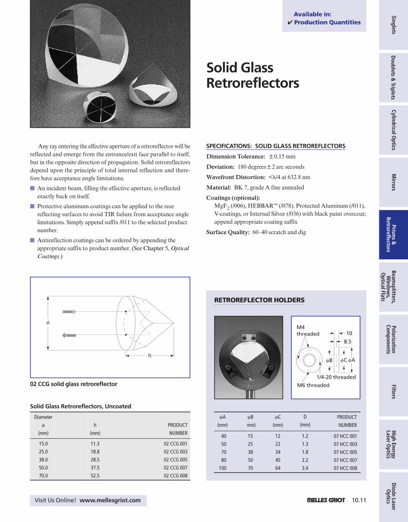
Any ray entering the effective aperture of a retroreflector will bereflected and emerge from the entrance/exit face parallel to itself,but in the opposite direction of propagation. Solid retroreflectorsdepend upon the principle of total internal reflection and there-fore have acceptance angle limitations.
$ An incident beam, filling the effective aperture, is reflectedexactly back on itself.
$ Protective aluminum coatings can be applied to the rearreflecting surfaces to avoid TIR failure from acceptance anglelimitations. Simply append suffix /011 to the selected productnumber.
$ Antireflection coatings can be ordered by appending theappropriate suffix to product number. (See Chapter 5, OpticalCoatings.)
SPECIFICATIONS: SOLID GLASS RETROREFLECTORS
Dimension Tolerance: 80.15 mm
Deviation: 180 degrees82 arc seconds
Wavefront Distortion: <l/4 at 632.8 nm
Material: BK 7, grade A fine annealed
Coatings (optional):MgF2 (/006), HEBBAR™ (/078), Protected Aluminum (/011),V-coatings, or Internal Silver (/036) with black paint overcoat;append appropriate coating suffix
Surface Quality: 60–40 scratch and dig
Solid GlassRetroreflectors
h
f
02 CCG solid glass retroreflector
Solid Glass Retroreflectors, Uncoated
Diameter
f
(mm)
h
(mm)
PRODUCT
NUMBER
15.0
25.0
38.0
50.0
70.0
11.3
18.8
28.5
37.5
52.5
02 CCG 001
02 CCG 003
02 CCG 005
02 CCG 007
02 CCG 008
RETROREFLECTOR HOLDERS
fB fC fA
M6 threaded
10
8.5
M4 threaded
1/4-20 threaded
fA
(mm)
fB
(mm)
D
(mm)PRODUCT
NUMBER
40
50
70
80
100
15
25
38
50
70
1.2
1.3
1.8
2.2
3.4
07 HCC 001
07 HCC 003
07 HCC 005
07 HCC 007
07 HCC 008
fC
(mm)
12
22
34
45
64
Available in:✔ Production Quantities
Chpt. 10 Final 8/28/99 2:21 PM Page 10.11

10.12 1 Visit Us OnLine! www.mellesgriot.com
Sing
lets
Dou
blet
s &
Trip
lets
Cylin
dric
al O
ptic
sM
irro
rsPr
ism
s &
Retr
oref
lect
ors
Beam
split
ters
, W
indo
ws,
O
ptic
al F
lats
Pola
riza
tion
Com
pone
nts
Filt
ers
Hig
h En
ergy
Lase
r Opt
ics
Dio
de L
aser
Opt
ics
Hollow retroreflectors consist of three flat mirrors assembled intoa mutually orthogonal inside corner. Since the optical path for theseretroreflectors is air, they are usable throughout the entire opticalspectrum from the ultraviolet to the far-infrared.
$ These reflectors eliminate wavelength dispersion effects.
$ Aluminum with a protective overcoat is standard on theseretroreflectors to ensure high reflectivity over the visiblespectrum. A gold coating for improved IR performance and aUV-enhanced aluminum coating can also be provided on aspecial order basis.
$ These retroreflectors are available with an excellent wavefrontdistortion specification up to l/8, along with a tight beamdeviation specification of 0.5 arc seconds.
$ Hollow retroreflectors are used to construct delay lines forfemtosecond applications. Other applications includepollution detection and measurement applications, laserranging, conventional and FTIR spectroscopy, distancemeasurement, holography, and interferometric applications.
SPECIFICATIONS:BROADBAND HOLLOW RETROREFLECTORS
Coating: Aluminum with protective overcoat
Mirror Substrates: Low expansion borosilicate glass
Surface Quality: 80–50 scratch and dig
Housing: Black anodized aluminum
Mounting:Base plate with M6 and ¼-20 hole patterns(both ¼-20 and M6 screws are included)
Broadband HollowRetroreflectors
33 12.7
12.5
1 hole threadedM6 x 1.0 deep
4 holes f7 thrucounterboredf11 x 7 deep
f41
66 50.6
7.7 50.6
66
1 hole threaded1/4-20 x 1.0 deep
7.7
1 hole M6 thru 1 hole 1/4-20 thru
f25.4
33
12.0
dimensions in mm
02 CCH 001–007 broadband hollow retroreflectors
Broadband Hollow Retroreflectors
Entrance
Aperture
(mm)
Beam
Deviation
(arc sec)
Wavefront
Distortion
(at 632.8 nm)
PRODUCT
NUMBER
25.4
25.4
25.4
63.5
63.5
63.5
127
30
5
1
30
5
1
30
3l
1l
l/6
3l
1l
l/6
3l
02 CCH 001
02 CCH 003
02 CCH 005
02 CCH 009
02 CCH 011
02 CCH 013
02 CCH 017
Chpt. 10 Final 8/28/99 2:21 PM Page 10.12

SingletsD
oublets & Triplets
Cylindrical Optics
Mirrors
Prisms &
RetroreflectorsBeam
splitters,W
indows,
Optical Flats
PolarizationCom
ponentsFilters
High Energy
Laser Optics
Diode Laser O
pticsVisit Us Online! www.mellesgriot.com 1 10.13
1 hole threadedM6 x 1.0 deep
4 holes f7 thrucounterboredf11 x 7 deep
1 hole 1/4-20x 1.0 deep
M6 x thru
71.56
35.78
12.22
12.22
35.78
71.5696
44.8
12.0
f82.5
f63.5
4 holes 1/4-20 thru on f2.0 bolt circle 90° apart
dimensions in mm
02 CCH 009–013 broadband hollow retroreflectors
4 holes threaded 1/4-20 thruon f4 bolt circlecountersink f7 x 90° both sides
f127
17085
152.476.2
160
80
101.6
50.8
120.812.7
f152.4
4 holes threaded M6 thruon f4 bolt circlecountersink f7 x 90° both sides
4 holes f7 thru f11.0 counterbored7.0 deepwill accommodate metric and inchhole patterns
dimensions in mm
02 CCH 017 broadband hollow retroreflector
Chpt. 10 Final 8/28/99 2:21 PM Page 10.13

10.14 1 Visit Us OnLine! www.mellesgriot.com
Sing
lets
Dou
blet
s &
Trip
lets
Cylin
dric
al O
ptic
sM
irro
rsPr
ism
s &
Retr
oref
lect
ors
Beam
split
ters
, W
indo
ws,
O
ptic
al F
lats
Pola
riza
tion
Com
pone
nts
Filt
ers
Hig
h En
ergy
Lase
r Opt
ics
Dio
de L
aser
Opt
ics
10.14 1 Visit Us OnLine! www.mellesgriot.com10.14 1 Visit Us OnLine! www.mellesgriot.com
Post-Mounted Prism Holders Precision Prism Tables
Miniature Prism Table Retroreflector Holders
Allows post mounting of prisms up to 50 mm (2 inch)in size, and permit precise tilt adjustment in two axes.
This miniature prism table allows tilt adjustment and360° rotation for components of up to 15 mm in size.
For precision applications, this table mounted prismholder provides fine adjustment in all three tilt axes.
Post mounted holders are available for all standardretroreflectors. By retaining the retroreflector near theedge, they ensure that total internal reflection is notdisturbed.
PRISM HOLDERS
Prisms frequently have to be positioned and aligned to tight tolerances, however, their odd shapes often make this difficult to accomplish. Melles Griot offers a number of prism holders to facilitate this task in the laboratory.See Chapter 25, Mirrors/Beamsplitter Mounts and Prism Tables.
Chpt. 10 Final 8/28/99 2:21 PM Page 10.14