prisma optical networks ancillary modules - mymyia · 2 prisma optical networks - ancillary modules...
TRANSCRIPT
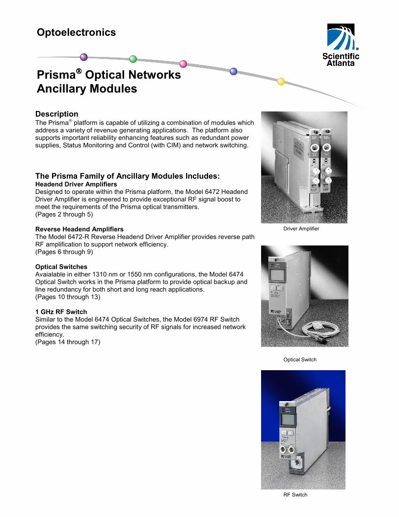
Description The Prisma platform is capable of utilizing a combination of modules which address a variety of revenue generating applications. The platform also supports important reliability enhancing features such as redundant power supplies, Status Monitoring and Control (with CIM) and network switching. The Prisma Family of Ancillary Modules Includes: Headend Driver Amplifiers Designed to operate within the Prisma platform, the Model 6472 Headend Driver Amplifier is engineered to provide exceptional RF signal boost to meet the requirements of the Prisma optical transmitters. (Pages 2 through 5) Reverse Headend Amplifiers The Model 6472-R Reverse Headend Driver Amplifier provides reverse path RF amplification to support network efficiency. (Pages 6 through 9) Optical Switches Avaialable in either 1310 nm or 1550 nm configurations, the Model 6474 Optical Switch works in the Prisma platform to provide optical backup and line redundancy for both short and long reach applications. (Pages 10 through 13) 1 GHz RF Switch Similar to the Model 6474 Optical Switches, the Model 6974 RF Switch provides the same switching security of RF signals for increased network efficiency. (Pages 14 through 17)
Optoelectronics
Prisma Optical Networks Ancillary Modules
Driver Amplifier
Optical Switch
RF Switch
2
Prisma Optical Networks - Ancillary Modules
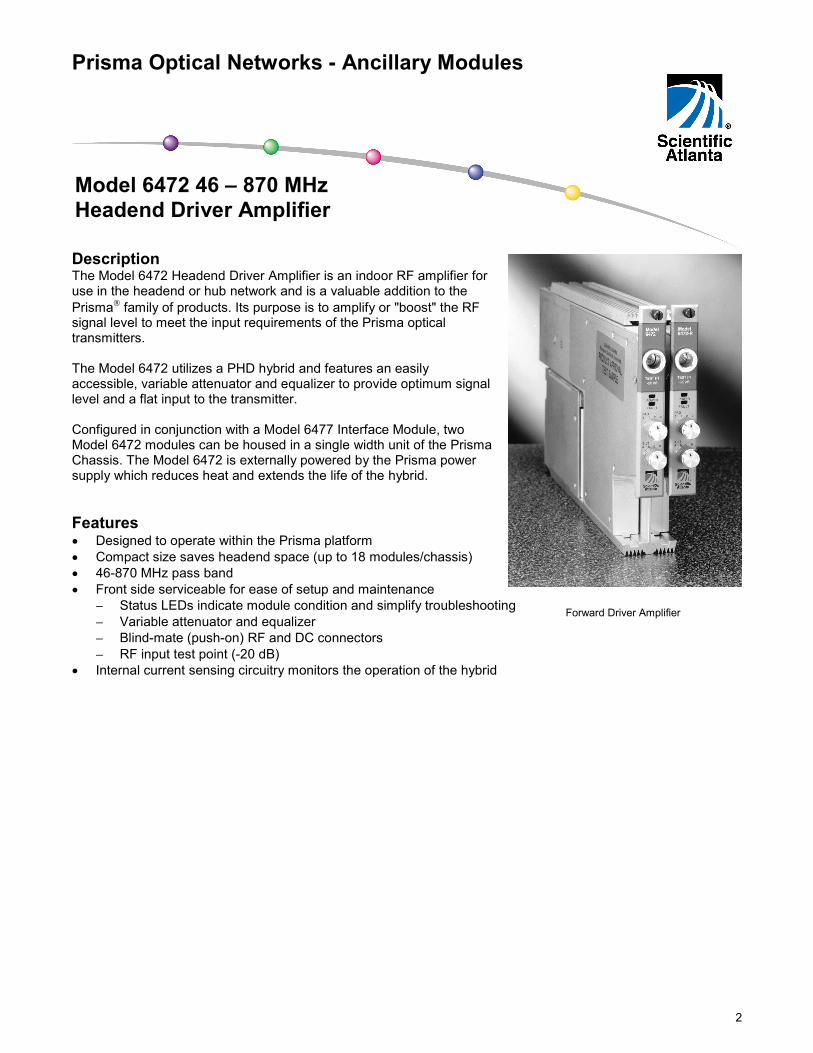
Description The Model 6472 Headend Driver Amplifier is an indoor RF amplifier for use in the headend or hub network and is a valuable addition to the Prisma family of products. Its purpose is to amplify or "boost" the RF signal level to meet the input requirements of the Prisma optical transmitters. The Model 6472 utilizes a PHD hybrid and features an easily accessible, variable attenuator and equalizer to provide optimum signal level and a flat input to the transmitter. Configured in conjunction with a Model 6477 Interface Module, two Model 6472 modules can be housed in a single width unit of the Prisma Chassis. The Model 6472 is externally powered by the Prisma power supply which reduces heat and extends the life of the hybrid. Features • Designed to operate within the Prisma platform • Compact size saves headend space (up to 18 modules/chassis) • 46-870 MHz pass band • Front side serviceable for ease of setup and maintenance
− Status LEDs indicate module condition and simplify troubleshooting − Variable attenuator and equalizer − Blind-mate (push-on) RF and DC connectors − RF input test point (-20 dB)
• Internal current sensing circuitry monitors the operation of the hybrid
Model 6472 46 – 870 MHz Headend Driver Amplifier
Forward Driver Amplifier
3
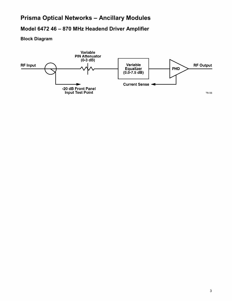
Prisma Optical Networks – Ancillary Modules Model 6472 46 – 870 MHz Headend Driver Amplifier Block Diagram
4
Prisma Optical Networks – Ancillary Modules Model 6472 46 – 870 MHz Headend Driver Amplifier Specifications RF Units Notes RF Bandwidth MHz 46 – 870 Frequency Response (deviation from flat response) dB ± 0.55 Return Loss (minimum) Input Typical
dB 17 @ 46 – 750 MHz 16 @ 750 – 860 MHz 15 @ 860 – 870 MHz
3
Return Loss (minimum) Output Typical
dB 14.5 @ 46 – 600 MHz 14 @ 600 – 860 MHz 13 @ 860 – 870 MHz
4
Noise Figure (maximum) dB 10.5 @ 50 MHz 12.5 @ 750 MHz 13.5 @ 870 MHz
3
Module Gain (minimum) (typical)
dB 13.5 14.0
Variable Attenuator 0 – 3 dB in 1 dB steps Variable Equalizer 0 – 7.5 dB in 1.5 dB steps Distortions Composite Triple Beat Composite Second Order Cross Modulation
TYPICAL 83.5 75.0 89.0
MINIMUM 82.0 73.0 86.0
1
RF Test Points dB -20.0 ± 1.0 dB Electrical Units Notes Operating Temperature Range °C
°F 0 to 50 +32 to +122
5
Power Supply (nominal) V DC 24 Power Consumption W DC 17.0 maximum Mechanical Units Notes Physical Dimensions Depth
in. cm
12.0 30.5
2
Width in. cm
1.6 4.1
2
Height in. cm
6.4 16.3
2
Weight lbs kg
3.0 1.4
2
Notes: 1. Distortions measured with 110 unmodulated (CW) NTSC analog channels at 30 dBmV flat output (46-870 MHz).
Distortions may degrade 0.5 dB at high temperature. 2. With Model 6477 Interface Module and two Model 6472 HEDAs. 3. With attenuator and equalizer set to 0.0 dB. 4. Return loss can degrade by 1 dB at high temperature. 5. Recommended for use only in non-condensing environments.
Unless other wise notes, specifications are based on measurements made in accordance with NCTA Practices for Measurements on Cable Television Systems using standard frequency assignments and are referenced to 30°C (86°F) at the inlet to the Chassis cooling fans.
5
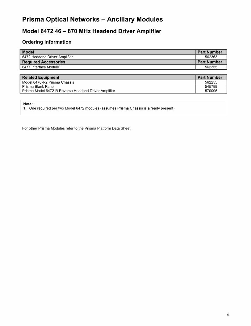
Prisma Optical Networks – Ancillary Modules Model 6472 46 – 870 MHz Headend Driver Amplifier Ordering Information Model Part Number 6472 Headend Driver Amplifier 562363 Required Accessories Part Number 6477 Interface Module1 562355 Related Equipment Part Number Model 6470-R2 Prisma Chassis 562255 Prisma Blank Panel 545799 Prisma Model 6472-R Reverse Headend Driver Amplifier 570096 For other Prisma Modules refer to the Prisma Platform Data Sheet.
Note: 1. One required per two Model 6472 modules (assumes Prisma Chassis is already present).

6
Prisma Optical Networks – Ancillary Modules
Description The Prisma platform is capable of utilizing a combination of modules which address a variety of revenue generating applications. The platform also supports important reliability enhancing features such as redundant power supplies, Status Monitoring and Control (with CIM) and network switching. The Model 6472-R Reverse Headend Driver Amplifier is designed to add to this flexibility. The Model 6472-R provides amplification in the reverse path RF bandwidth and is typically an integral part of the reverse combining network. Ease of installation, setup, and maintenance are inherent with the Model 6472-R and are of great benefit in both complex and basic 2-way systems. When used with other Prisma modules, such as the Model 6971-DR Dual Reverse Receiver, the Model 6472-R can provide advanced RF signal level control for deployment of advanced reverse path services. Features • Designed to operate within the Prisma platform • Compact size saves headend space • 5 - 200 MHz pass band • Front side serviceable for ease of setup and maintenance
− Status LEDs indicate module condition and simplify troubleshooting − Variable attenuator and equalizer − Blind-mate (push-on) RF and DC connectors − RF input test point (-20 dB)
• Internal current sensing circuitry monitors the operation of the hybrid
Model 6472-R 5 – 200 MHz Reverse Headend Driver Amplifier
Reverse Driver Amplifier

7
Prisma Optical Networks – Ancillary Modules Model 6472-R 5 – 200 MHz Reverse Headend Driver Amplifier Block Diagram
8
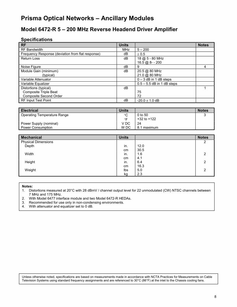
Prisma Optical Networks – Ancillary Modules Model 6472-R 5 – 200 MHz Reverse Headend Driver Amplifier Specifications RF Units Notes RF Bandwidth MHz 5 – 200 Frequency Response (deviation from flat response) dB ± 0.5 Return Loss dB 18 @ 5 - 80 MHz
16.5 @ 8- - 200
Noise Figure dB 9 4 Module Gain (minimum) (typical)
dB 20.5 @ 80 MHz 21.0 @ 80 MHz
Variable Attenuator 0 – 3 dB in 1 dB steps Variable Equalizer 0.5 – 5.5 dB in 1 dB steps Distortions (typical) Composite Triple Beat Composite Second Order
dB 75 72
1
RF Input Test Point dB -20.0 ± 1.0 dB Electrical Units Notes Operating Temperature Range °C
°F 0 to 50 +32 to +122
3
Power Supply (nominal) V DC 24 Power Consumption W DC 8.1 maximum Mechanical Units Notes Physical Dimensions Depth
in. cm
12.0 30.5
2
Width in. cm
1.6 4.1
2
Height in. cm
6.4 16.3
2
Weight lbs kg
5.0 2.3
2
Notes: 1. Distortions measured at 20°C with 28 dBmV / channel output level for 22 unmodulated (CW) NTSC channels between
7 MHz and 175 MHz. 2. With Model 6477 interface module and two Model 6472-R HEDAs. 3. Recommended for use only in non-condensing environments. 4. With attenuator and equalizer set to 0 dB.
Unless otherwise noted, specifications are based on measurements made in accordance with NCTA Practices for Measurements on Cable Television Systems using standard frequency assignments and are referenced to 30°C (86°F) at the inlet to the Chassis cooling fans.
9
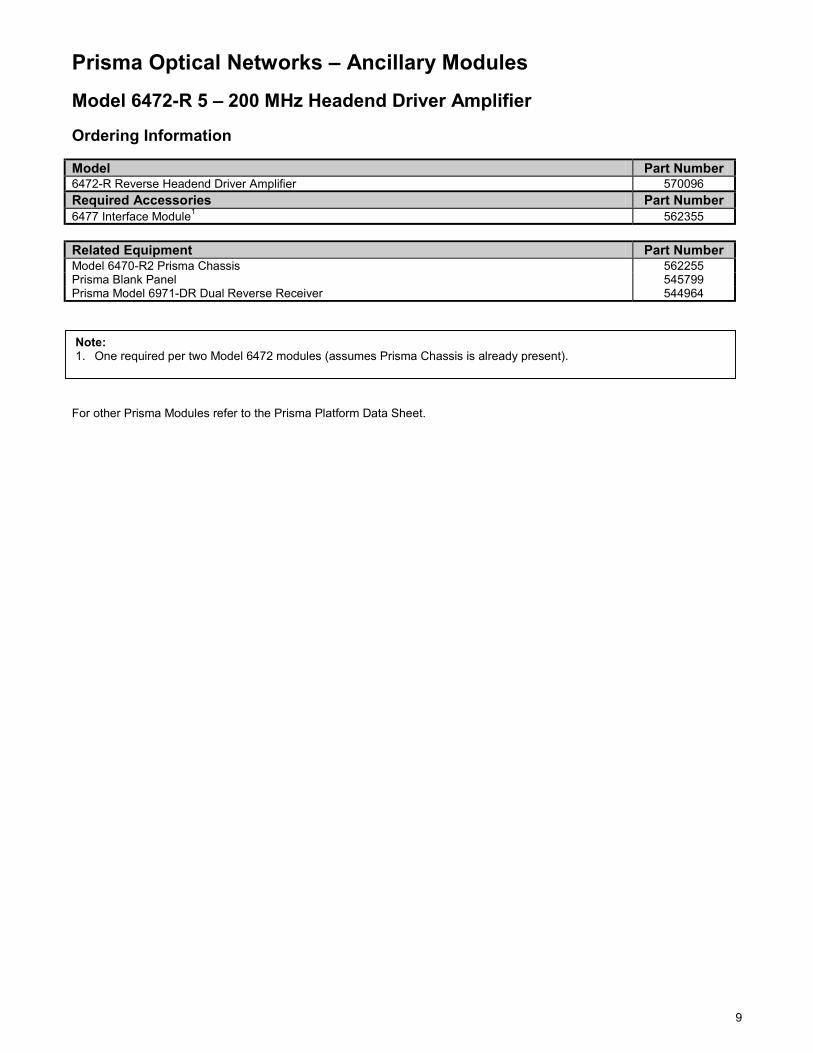
Prisma Optical Networks – Ancillary Modules Model 6472-R 5 – 200 MHz Headend Driver Amplifier Ordering Information Model Part Number 6472-R Reverse Headend Driver Amplifier 570096 Required Accessories Part Number 6477 Interface Module1 562355 Related Equipment Part Number Model 6470-R2 Prisma Chassis 562255 Prisma Blank Panel 545799 Prisma Model 6971-DR Dual Reverse Receiver 544964 For other Prisma Modules refer to the Prisma Platform Data Sheet.
Note: 1. One required per two Model 6472 modules (assumes Prisma Chassis is already present).

10
Prisma Optical Networks – Ancillary Modules
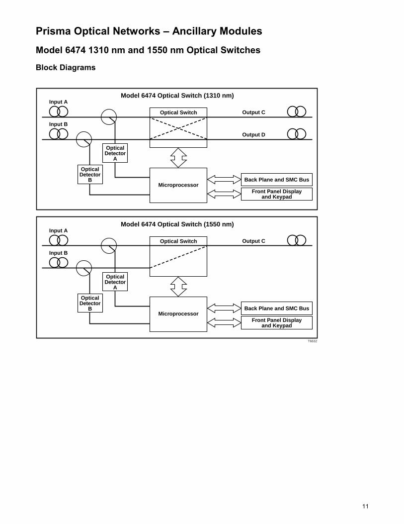
Description The Prisma platform is capable of using a combination of modules which address a variety of revenue-generating applications. The platform also supports important reliability enhancing features such as redundant power supplies, Status Monitoring and Control (with CIM), and network switching. The Model 6474 1550 and 1310 nm Optical Switches add to the reliability of the Prisma platform by providing optical backup and redundancy. The 1550 nm wavelength is typically used in high power / long-haul systems which employ externally modulated transmitters and in-line optical amplifiers. The 1550 nm optical switch provides backup for both these devices. The 1310 nm wavelength is typically used in HFC type networks with relatively short optical spans. The 1310 nm optical switch provides for transmitter, receiver, and/or optical path redundancy. Both the 1310 and 1550 nm optical switches can be switched by any one of four methods: loss of light, front panel (manual) operation, status monitoring and control, or external alarm input. Another important feature is switch hysteresis. These two user definable values prevent the switch from going back to the primary input until it is completely stable. Features • Designed to operate within the Prisma platform (single-width module) • Provides redundancy for long or short haul links • Loss of optical power detection • Large optical power dynamic range (-13 to +18 dBm) • Front side serviceable for ease of setup and maintenance
− Advanced LCD display − Status LEDs indicate module condition and simplify troubleshooting − Blind-mate (push-on) RF and DC connectors
• Time out setting (set by user) that prevents false reactivation of the switch before a reliable signal has been restored
• Input power threshold (set by user) to determine when a switch occurs • Both automatic and manual switch modes • Status Monitoring and Control capable • Can be connected to an external alarm system
Model 6474 1310 nm and 1550 nm Optical Switches
Optical Switch
11
Prisma Optical Networks – Ancillary Modules Model 6474 1310 nm and 1550 nm Optical Switches Block Diagrams
Optical Switch
T6632
Input A
Output C
Model 6474 Optical Switch (1310 nm)
OpticalDetector
A
Input B
Output D
OpticalDetector
BMicroprocessor
Back Plane and SMC Bus
Front Panel Displayand Keypad
Optical Switch
Input A
Output C
Model 6474 Optical Switch (1550 nm)
OpticalDetector
A
Input B
OpticalDetector
BMicroprocessor
Back Plane and SMC Bus
Front Panel Displayand Keypad

12
Prisma Optical Networks – Ancillary Modules Model 6474 1310 nm and 1550 nm Optical Switches Specification Optical Units Notes Optical Interface Pigtail SC/APC SC/UPC FC/UPC E2000/APC
Standard Optional Optional Optional
4
Nominal Optical Wavelength nm 1290 – 1330 nm for P/N 568000 1530 – 1570 nm for P/N 567999
Optical Input Power Range dBm -13 to +18 1 Return Loss dB ≥ 60 3 Insertion Loss dB 0.85 @ 1310 nm
1.35 @ 1550 nm 3
Cross Talk dB >20 @ 1310 nm >50 @ 1550 nm
Electrical Units Notes Sense and Switch Time ms <60 Operating Temperature Range °C
°F 0 to +50 +32 to +122
2
Power Consumption W DC 4W maximum (when switching) 2W typical
Switching Threshold dB 1 – 10 (user changeable) Restore Threshold dB 0.5 – 9.5 (user changeable) Wait Time Minutes 0 – 12 in 0.5 minute steps Mechanical Units Notes Physical Dimensions Depth
in. cm
12.0 30.5
Width in. cm
1.6 4.1
Height in. cm
6.4 16.3
Weight lbs kg
6 2.7
Notes: 1. Optical input power of -3.0 dBm or greater is required to maintain the full user-controlled threshold range. When the
optical input power is less than -3 dBm there is a 1 for 1 reduction in threshold range. 2. Recommended for use only in non-condensing environments. 3. For the optical switch only, without optical connectors. When used with an optical connector, the module return losses
and insertion losses are determined by the performance of the optical connector. 4. Pigtail is approximately 3 meters long.
Unless otherwise noted, specifications are based on measurements made in accordance with NCTA Practices for Measurements on Cable Television Systems using standard frequency assignments and are referenced to 30°C (86°F) at the inlet to the Chassis cooling fans.
13
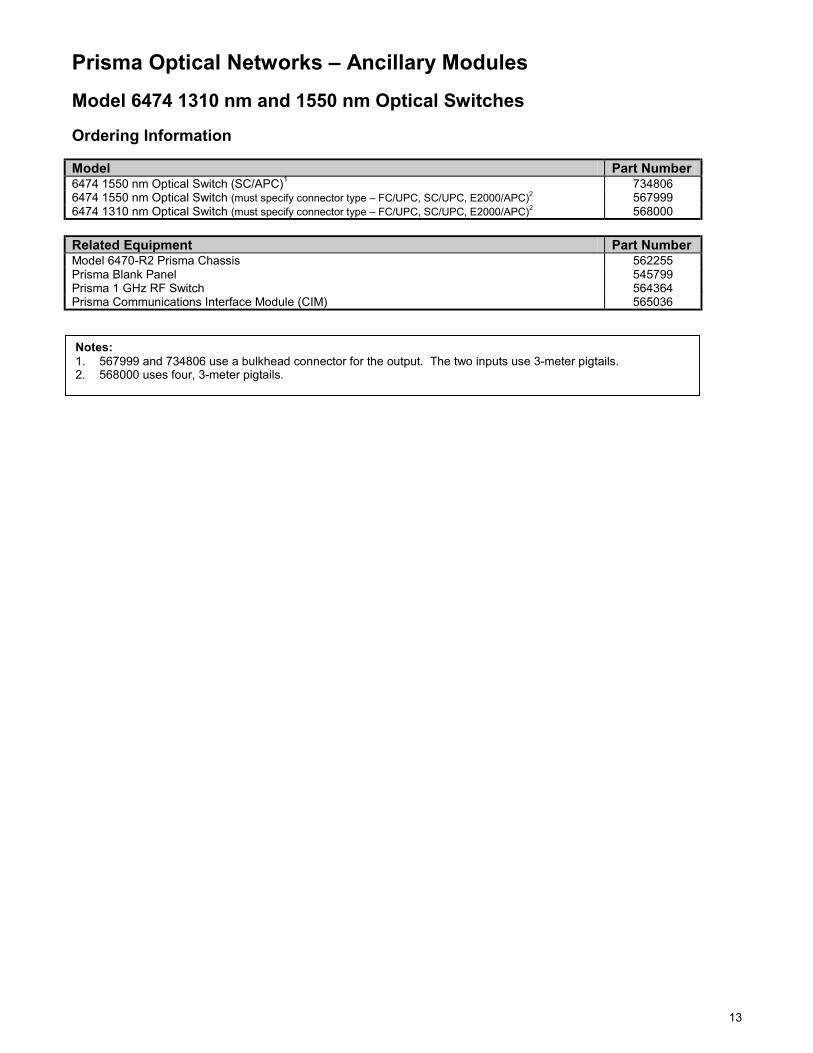
Prisma Optical Networks – Ancillary Modules Model 6474 1310 nm and 1550 nm Optical Switches Ordering Information Model Part Number 6474 1550 nm Optical Switch (SC/APC)1 734806 6474 1550 nm Optical Switch (must specify connector type – FC/UPC, SC/UPC, E2000/APC)2 567999 6474 1310 nm Optical Switch (must specify connector type – FC/UPC, SC/UPC, E2000/APC)2 568000 Related Equipment Part Number Model 6470-R2 Prisma Chassis 562255 Prisma Blank Panel 545799 Prisma 1 GHz RF Switch 564364 Prisma Communications Interface Module (CIM) 565036
Notes: 1. 567999 and 734806 use a bulkhead connector for the output. The two inputs use 3-meter pigtails. 2. 568000 uses four, 3-meter pigtails.
14
Prisma Optical Networks – Ancillary Modules
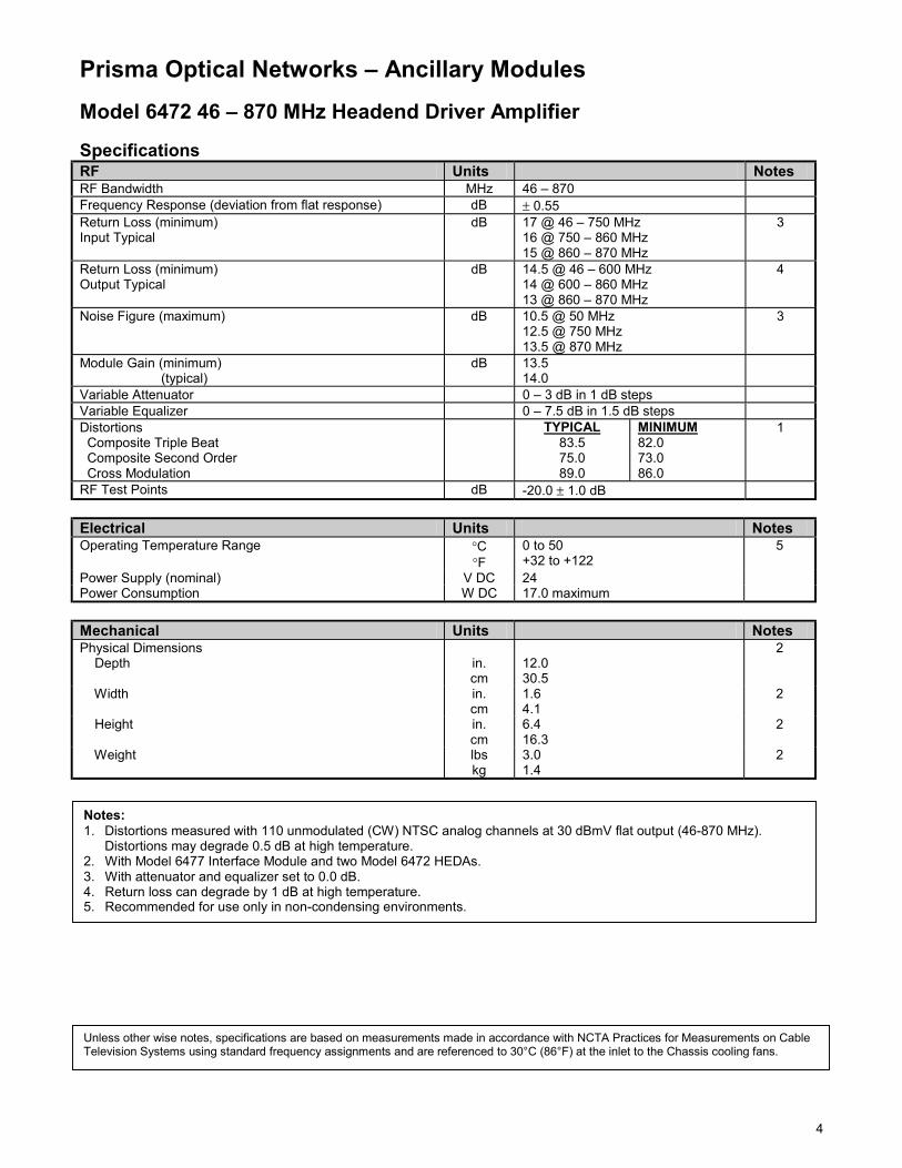
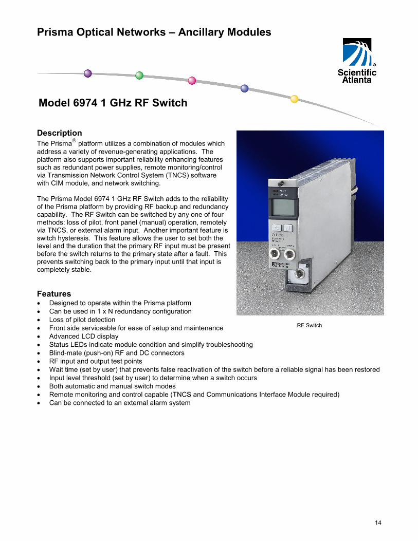
Description The Prisma platform utilizes a combination of modules which address a variety of revenue-generating applications. The platform also supports important reliability enhancing features such as redundant power supplies, remote monitoring/control via Transmission Network Control System (TNCS) software with CIM module, and network switching. The Prisma Model 6974 1 GHz RF Switch adds to the reliability of the Prisma platform by providing RF backup and redundancy capability. The RF Switch can be switched by any one of four methods: loss of pilot, front panel (manual) operation, remotely via TNCS, or external alarm input. Another important feature is switch hysteresis. This feature allows the user to set both the level and the duration that the primary RF input must be present before the switch returns to the primary state after a fault. This prevents switching back to the primary input until that input is completely stable. Features • Designed to operate within the Prisma platform • Can be used in 1 x N redundancy configuration • Loss of pilot detection • Front side serviceable for ease of setup and maintenance • Advanced LCD display • Status LEDs indicate module condition and simplify troubleshooting • Blind-mate (push-on) RF and DC connectors • RF input and output test points • Wait time (set by user) that prevents false reactivation of the switch before a reliable signal has been restored • Input level threshold (set by user) to determine when a switch occurs • Both automatic and manual switch modes • Remote monitoring and control capable (TNCS and Communications Interface Module required) • Can be connected to an external alarm system
Model 6974 1 GHz RF Switch
RF Switch

15
Prisma Optical Networks – Ancillary Modules Model 6974 1 GHz RF Switch Block Diagram
Input A
Input B
Pad
Pad
Plug-InFilter Detector
To Controller
Plug-InFilter Detector
To Controller
From Controller
From Controller
From Controller
To Test Point B
To Test Point A
To OutputTest Point
RFOutput

16
Prisma Optical Networks – Ancillary Modules Model 6974 1 GHz RF Switch Specifications General RF Performance Units Notes Passband MHz 5 - 1000 Frequency Response dB ± 0.4 RF Input Range dBmv 15 -50 2,3 Return Loss 5 - 1000 MHz dB 15 RF Isolation - port to port dB > 60 3 Insertion Loss See Chart (below) 1 RF Test Points Input relative to RF output port ± 1.5 dB Output relative to RF output port ± 1.0 dB
dB dB
-30 -30
Sense and Switch time ms > 60 Switch Hysterisis Switch level Detector Accuracy Return Level Return Time
dB dB dB
Min.
1 - 10 in 0.5 dB steps
± 0.5 0.5 - 9.5 in 0.5 dB steps
0 - 12 in 0.5 Minute steps
2 2 2
RF Detector Pilot Frequency MHz See Ordering Information Electrical Units Notes Operating Temperature Range °C
°F 0 to 50 +32 to +122
4
Power Consumption W DC 7.6 Mechanical Units Notes Physical Dimensions Depth
in. cm
12.0 30.5
Width in. cm
1.6 4.1
Height in. cm
6.4 16.3
Weight lbs kg
6.0 2.7
Insertion Losses Frequency (MHz) 5 40 50 65 70 88 550 750 870 1000 Typical 1.49 1.06 1.06 1.07 1.05 0.97 1.58 1.86 2.06 2.33 Maximum 1.52 1.07 1.07 1.08 1.07 0.99 1.59 1.88 2.10 2.40
Notes: 1. With 0 dB plug-in pads. 2. When the RF input level is below +25 dBmV the detection accuracy for switching threshold is 1.5 dB. 3. RF input levels must be within 20 dB of each other to maintain 60 dB minimum isolation. 4. Recommended for use in non-condensing environments.
Unless otherwise noted, the above specifications reflect typical station performance in the recommended operating configuration (s). Specifications are based on measurements made in accordance with NCTA Recommended Practices for Measurements on Cable Television Systems using standard frequency assignments and are referenced to 20°C (68°F) at the inlet to the chassis cooing fans

17
Prisma Optical Networks – Ancillary Modules Model 6974 1 GHz RF Switch Ordering Information Model Part Number 6974 RF Switch (w/448.00 MHz Pilot filter) 570571 6974 RF Switch (w/445.25 MHz Pilot filter) 715816 Related Equipment Part Number Model 6470-R2 Prisma Chassis 562255 Prisma Blank Panel 545799 Model 6474 Optical Switch 1310 nm 568000 Model 6474 Optical Switch 1550 nm 567999 Model 6478 Communications Interface Module (CIM) 565036
Scientific-Atlanta, the Scientific-Atlanta logo, and Prisma are registered trademarks of Scientific-Atlanta, Inc. Specifications and product availability are subject to change without notice. 2001 Scientific-Atlanta, Inc. All rights reserved. Scientific-Atlanta, Inc. 1-800-722-2009 or 770-903-6900 www.scientificatlanta.com Part Number 747915 Rev A June 2001