print preview - c:docume~1 ernamelocals~1temp ...bweb.brp-jp.com/pdf/skpd2016-4 en.pdf · important...
TRANSCRIPT

PRE-DELIVERYBULLETIN
SKI-DOO®
June 2015 Subject:Ski-Doo REV-XS and REV-XM PredeliveryInspection
No. 2016-4
YEAR MODEL
2016 REV-XS and REV-XM
TABLE OF CONTENTSPage Page
IMPORTANT NOTICE ..... . . . . . . . . . . . . . . . . . . 3High altitude calibration... . . . . . . . . . . . . . . . . . . . . . 3
UPDATE SUMMARY.... .. . . . . . . . . . . . . . . . . . . 4
MODEL LISTING..... . . . . . . . . . . . . . . . . . . . . . . . . 4
PREDELIVERY KIT PARTS LIST ..... . . . . . 5
1- UNCRATING...... . . . . . . . . . . . . . . . . . . . . . . . . . 8Crate Cover.. . . . . . . . . . . . . . . . . . . . . . . . . . . . . . . . . . . . . 8Crate Brackets .. . . . . . . . . . . . . . . . . . . . . . . . . . . . . . . . . 8Crate Disposal. . . . . . . . . . . . . . . . . . . . . . . . . . . . . . . . . . . 9Rear Suspension Shipping Hook(s) . . . . . . . . . . 9
2- PARTS TO BE INSTALLED ...... . . . . . . . 10Front Shock Absorbers ... . . . . . . . . . . . . . . . . . . . . . 10Skis .. . . . . . . . . . . . . . . . . . . . . . . . . . . . . . . . . . . . . . . . . . . . . . 13Ski flotation extension .. . . . . . . . . . . . . . . . . . . . . . . . 16Battery ... . . . . . . . . . . . . . . . . . . . . . . . . . . . . . . . . . . . . . . . . 16Handlebar ... . . . . . . . . . . . . . . . . . . . . . . . . . . . . . . . . . . . . . 18Steering Cover .. . . . . . . . . . . . . . . . . . . . . . . . . . . . . . . . . 19Handlebar Wind Deflector (ApplicableModels) .. . . . . . . . . . . . . . . . . . . . . . . . . . . . . . . . . . . . . . . . . 20Tools and Emergency Starting Rope... . . . . . . 21Heated Visor Extension (Expedition, GrandTouring and Renegade Enduro) .. . . . . . . . . . . . . . 22Drive Belt Installation .. . . . . . . . . . . . . . . . . . . . . . . . . 22Passenger Seat Installation (Expedition Sportand Grand Touring Sport) . . . . . . . . . . . . . . . . . . . . . . 23Passenger Seat and Heated Handholds (GrandTouring Models). . . . . . . . . . . . . . . . . . . . . . . . . . . . . . . . . 24Tunnel Bag (Grand Touring SE) .. . . . . . . . . . . . . . 26Saddlebags (Grand Touring SE) .. . . . . . . . . . . . . . 26
Hitch (Expedition Sport and Grand TouringSport Europe) . . . . . . . . . . . . . . . . . . . . . . . . . . . . . . . . . . . 26Snow Guard ... . . . . . . . . . . . . . . . . . . . . . . . . . . . . . . . . . . 27Rear Bumper .. . . . . . . . . . . . . . . . . . . . . . . . . . . . . . . . . . . 27Side Reflectors... . . . . . . . . . . . . . . . . . . . . . . . . . . . . . . . 27Front Reflector (European Models) . . . . . . . . . . 27Snowboard and Ski Rack (Summit BurtonModel). . . . . . . . . . . . . . . . . . . . . . . . . . . . . . . . . . . . . . . . . . . . 29
3- FLUIDS ..... . . . . . . . . . . . . . . . . . . . . . . . . . . . . . . . . 29General Guidelines ... . . . . . . . . . . . . . . . . . . . . . . . . . . 29Fuel .. . . . . . . . . . . . . . . . . . . . . . . . . . . . . . . . . . . . . . . . . . . . . . 29Engine Coolant... . . . . . . . . . . . . . . . . . . . . . . . . . . . . . . . 30Chaincase Oil. . . . . . . . . . . . . . . . . . . . . . . . . . . . . . . . . . . . 30Injection Oil. . . . . . . . . . . . . . . . . . . . . . . . . . . . . . . . . . . . . . 31Brake Fluid Level .. . . . . . . . . . . . . . . . . . . . . . . . . . . . . . 31Engine Oil (600 ACE, 900 ACE and 12004-TEC) .. . . . . . . . . . . . . . . . . . . . . . . . . . . . . . . . . . . . . . . . . . . 32
4- UPPER BODY MODULE INSTALLA-TION...... . . . . . . . . . . . . . . . . . . . . . . . . . . . . . . . . . . . . . . 32
Front Storage Compartment Cover ... . . . . . . . 33Console Wind Deflectors (if Equipped) .. . . . . 33Windshield.. . . . . . . . . . . . . . . . . . . . . . . . . . . . . . . . . . . . . . 34Mirrors (Grand Touring Models) .. . . . . . . . . . . . . 34
5- SET-UP ..... . . . . . . . . . . . . . . . . . . . . . . . . . . . . . . . . 34Doing All Recalls and All Other ModificationsRequested by BRP ... . . . . . . . . . . . . . . . . . . . . . . . . . . 34Programming Using B.U.D.S. .. . . . . . . . . . . . . . . . 34Track.. . . . . . . . . . . . . . . . . . . . . . . . . . . . . . . . . . . . . . . . . . . . . 36
Printed in Canada. (mbl2016-002 en ML)©2015 Bombardier Recreational Products Inc. and BRP US Inc. All rights reserved.
1 / 39®™ and the BRP logo are trademarks of Bombardier Recreational Products Inc. or its affiliates.

6- ADJUSTMENTS (CUSTOMERPREFERENCE) ..... . . . . . . . . . . . . . . . . . . . . . . . . . . . 38
Rear Suspension Adjustments .. . . . . . . . . . . . . . 38
7- FINAL INSPECTION...... . . . . . . . . . . . . . . . . 39Controls, Equipments, Movement andOperation Inspection... . . . . . . . . . . . . . . . . . . . . . . . . 39Test Run Snowmobile .. . . . . . . . . . . . . . . . . . . . . . . . 39Snowmobile Cleaned and in ShowroomCondition.. . . . . . . . . . . . . . . . . . . . . . . . . . . . . . . . . . . . . . . . 39Vehicle Delivery .. . . . . . . . . . . . . . . . . . . . . . . . . . . . . . . . 39
2 / 39 2016-4 PREDELIVERY

IMPORTANT NOTICE
IMPORTANT NOTICEThis bulletin must be used in conjunction with check list enclosed in bag with OPERATOR’S GUIDE. Makesure that PREDELIVERY CHECK LIST is completed and signed.
WARNING
To obtain limited warranty coverage, predelivery procedures must be performed by an autho-rized BRP Ski-Doo snowmobile dealer/distributor. Apply all necessary torques as indicated.
NOTE: The information and components/system descriptions contained in this document are correctat time of publication. Bombardier Recreational Products Inc. (BRP) however, maintains a policy ofcontinuous improvement of its products without imposing upon itself any obligation to install them onproducts previously manufactured.Due to late changes, there might be some differences between manufactured product and descriptionsand/or specifications in this document. BRP reserves the right at any time to discontinue or changespecifications, designs, features, models or equipment without incurring obligation.The illustrations in this document show typical construction of different assemblies and may notreproduce full detail or exact shape of parts. However, they represent parts that have same or similarfunction.Content of this bulletin is designed as a guideline only. All mechanics performing predelivery proceduresshould have attended current model year service training.Further information or inquiries should be directed to your distributor service representative and/orspecific SHOP MANUAL sections.Please complete PREDELIVERY CHECK LIST for each snowmobile and retain a customer signed copy.Make sure customer receives OPERATOR’S GUIDE, PREDELIVERY CHECK LIST signed copy andSAFETY DVD VIDEOThere is a tag attached to ignition key, only customer must remove it. This label will remind cus-tomer to ask dealer/distributor to perform suspension adjustments according to riding style andvehicle load.
WARNING
Torque wrench tightening specifications must strictly be adhered to. Where specified, install newlocking devices (e.g. lock tabs, elastic stop nuts). If the efficiency of a locking device is impaired,it must be renewed.
High altitude calibrationNOTE:
– Summit North American models are factory calibrated to be ridden at altitudes ranging from600 m to 2 400 m (2,000 ft to 8,000 ft).
– European Summit models and all other models are factory calibrated for sea level riding unless themodel is specifically stated as a High altitude model.
– If not re-calibrated for proper altitude use, severe engine damage may occur.– ALWAYS refer to model year HIGH ALTITUDE SERVICE BULLETIN.
PREDELIVERY 2016-4 3 / 39
MODEL LISTING
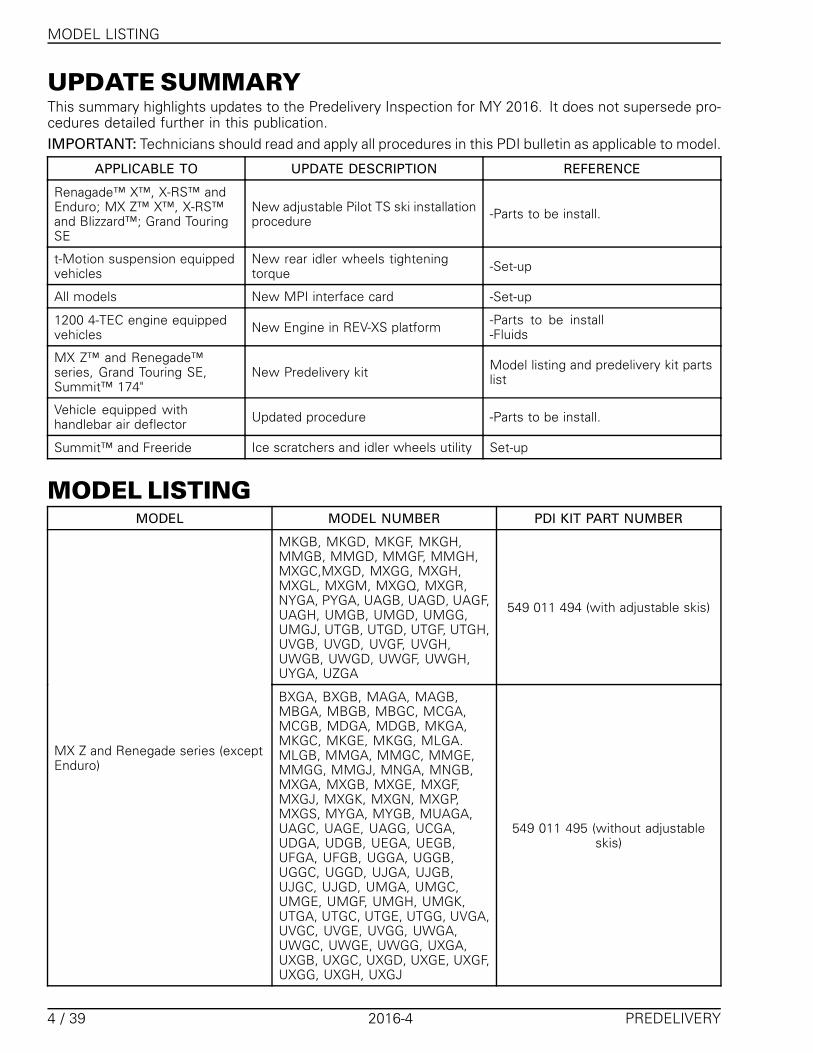
UPDATE SUMMARYThis summary highlights updates to the Predelivery Inspection for MY 2016. It does not supersede pro-cedures detailed further in this publication.IMPORTANT: Technicians should read and apply all procedures in this PDI bulletin as applicable to model.
APPLICABLE TO UPDATE DESCRIPTION REFERENCE
Renagade™ X™, X-RS™ andEnduro; MX Z™ X™, X-RS™and Blizzard™; Grand TouringSE
New adjustable Pilot TS ski installationprocedure -Parts to be install.
t-Motion suspension equippedvehicles
New rear idler wheels tighteningtorque -Set-up
All models New MPI interface card -Set-up
1200 4-TEC engine equippedvehicles New Engine in REV-XS platform -Parts to be install
-Fluids
MX Z™ and Renegade™series, Grand Touring SE,Summit™ 174"
New Predelivery kit Model listing and predelivery kit partslist
Vehicle equipped withhandlebar air deflector Updated procedure -Parts to be install.
Summit™ and Freeride Ice scratchers and idler wheels utility Set-up
MODEL LISTINGMODEL MODEL NUMBER PDI KIT PART NUMBER
MKGB, MKGD, MKGF, MKGH,MMGB, MMGD, MMGF, MMGH,MXGC,MXGD, MXGG, MXGH,MXGL, MXGM, MXGQ, MXGR,NYGA, PYGA, UAGB, UAGD, UAGF,UAGH, UMGB, UMGD, UMGG,UMGJ, UTGB, UTGD, UTGF, UTGH,UVGB, UVGD, UVGF, UVGH,UWGB, UWGD, UWGF, UWGH,UYGA, UZGA
549 011 494 (with adjustable skis)
MX Z and Renegade series (exceptEnduro)
BXGA, BXGB, MAGA, MAGB,MBGA, MBGB, MBGC, MCGA,MCGB, MDGA, MDGB, MKGA,MKGC, MKGE, MKGG, MLGA.MLGB, MMGA, MMGC, MMGE,MMGG, MMGJ, MNGA, MNGB,MXGA, MXGB, MXGE, MXGF,MXGJ, MXGK, MXGN, MXGP,MXGS, MYGA, MYGB, MUAGA,UAGC, UAGE, UAGG, UCGA,UDGA, UDGB, UEGA, UEGB,UFGA, UFGB, UGGA, UGGB,UGGC, UGGD, UJGA, UJGB,UJGC, UJGD, UMGA, UMGC,UMGE, UMGF, UMGH, UMGK,UTGA, UTGC, UTGE, UTGG, UVGA,UVGC, UVGE, UVGG, UWGA,UWGC, UWGE, UWGG, UXGA,UXGB, UXGC, UXGD, UXGE, UXGF,UXGG, UXGH, UXGJ
549 011 495 (without adjustableskis)
4 / 39 2016-4 PREDELIVERY

PREDELIVERY KIT PARTS LIST
MODEL MODEL NUMBER PDI KIT PART NUMBER
Renegade Enduro UBGA, UBGB, UNGA, UNGB,URGA, USGA 549 011 497
Expedition® Sport KCGA, KDGA, KDGB 549 011 445
ERGA 549 011 493 (with adjustable skis)Grand Touring series
EAGA, EPGA, ESGA, ETGA, ETGB 549 011 478 (without adjustableskis)
Freeride and Summit series (except174")
CDGA, CDGB, CDGC, CDGD,CDGE, CEGA, CEGB, CEGC, CEGD,CEGE, CEGF, CFGA, CFGB, CFGC,CFGD, CFGE, CFGF, CCGA, CCGB,CCGC, CCGD, CCGE, CCGF, CGGA,CGGB, CGGC, CGGD, CHGA,CHGB, CHGC, CHGD, CXGA,CXGB, CXGC, CXGD, CXGE, CXGF,TCGA, TCGB, TDGA, TDGB, TDGC,TDGD, TDGE, TDGF, TDGG, TDGH,TDGJ, TDGK, TDGL, TDGM, TJGA,TJGB, TJGC, TKGA, TKGB, TKGC,TKGD, TKGE, TKGF, TKGG, TKGH,TKGJ, TKGK, TKGL, TKGM, VAGA,VAGB, VAGC, VBGA, VBGB, VBGC,VBGD, VCGA, VCGB, VCGC, VCGD
549 011 480
Summit 174"
TEGA, TEGB, TEGC, TEGD, TEGE,TEGF, TEGG, TEGH, TEGJ,TEGK,TEGL, TEGN, CKGA, CKGB, CKGC,CKGD
549 011 496
PREDELIVERY KIT PARTSLIST
KIT 549 011 497 (RENEGADE ENDURO MODEL)
WHERE USED DESCRIPTION PART NUMBER QTY
Accessories Heated visor wire 515 175 851 1
Rear suspension Wheel Cap 503 192 771 2
M10 Washer 503 192 496 2Front suspension and skis
M10 flanged nut 233 201 464 6
Steering Torx screw 250 000 760 2
Rear bumper M6 X 18 Torx screw 250 000 779 4
3/16 pop rivet 293 150 108 4Snow guard
Washer 517 124 300 4
PREDELIVERY 2016-4 5 / 39

PREDELIVERY KIT PARTS LIST
KIT 549 011 478 (GRAND TOURING MODELS WITHOUT ADJUSTABLE SKIS)
WHERE USED DESCRIPTION PART NUMBER QTY
Accessories Heated visor wire 515 175 851 1
Rear suspension Wheel Cap 503 192 771 2
M10 Washer 503 192 496 2
M10 flanged nut 233 201 464 6Front suspension and skis
Ski stopper 505 072 594 2
Steering Torx screw 250 000 760 2
Washer 224 061 201 2
M6 X 16 screw 207 361 644 2Passenger seat
M6 X 30 screw 207 563 044 2
Washer 224 061 201 8Rear bumper
M6 X 18 Torx screw 250 000 779 8
3/16 pop rivet 293 150 108 4Snow guard
Washer 517 124 300 4
KIT 549 011 493 (GRAND TOURING MODELS WITH ADJUSTABLE SKIS)
WHERE USED DESCRIPTION PART NUMBER QTY
Accessories Heated visor wire 515 175 851 1
Rear suspension Wheel Cap 503 192 771 2
M10 Washer 503 192 496 2Front suspension and skis
M10 flanged nut 233 201 464 6
Steering Torx screw 250 000 760 2
Washer 224 061 201 2
M6 X 16 screw 207 361 644 2Passenger seat
M6 X 30 screw 207 563 044 2
Washer 224 061 201 8Rear bumper
M6 X 18 Torx screw 250 000 779 8
3/16 pop rivet 293 150 108 4Snow guard
Washer 517 124 300 4
KIT 549 011 494 (MX Z, AND RENEGADE MODELS WITH ADJUSTABLE SKIS EXCEPT ENDURO)
WHERE USED DESCRIPTION PART NUMBER QTY
Rear Suspension Wheel Cap 503 192 771 2
M10 Washer 503 192 496 2Front suspension and skis
M10 nuts 233 201 464 6
Washer 224 061 201 6Rear bumper
M6 X 18 Torx screw 250 000 779 4
3/16 pop rivet 293 150 108 4Snow guard
Washer 517 124 300 4
6 / 39 2016-4 PREDELIVERY

PREDELIVERY KIT PARTS LIST
KIT 549 011 495 (MX Z, AND RENEGADE MODELS WITHOUT ADJUSTABLE SKIS)
WHERE USED DESCRIPTION PART NUMBER QTY
Rear Suspension Wheel Cap 503 192 771 2
M10 Washer 503 192 496 2
M10 nuts 233 201 464 6Front suspension and skis
Ski stopper 505 072 594 2
Washer 224 061 201 6Rear bumper
M6 X 18 Torx screw 250 000 779 4
3/16 pop rivet 293 150 108 4Snow guard
Washer 517 124 300 4
KIT 549 011 445 (EXPEDITION MODELS)
WHERE USED DESCRIPTION PART NUMBER QTY
Accessories Heated visor wire 515 175 851 1
Rear suspension Wheel Cap 503 192 771 2
M10 Washer 503 192 496 2
M10 flanged nut 233 201 464 6Front suspension and skis
Ski stopper 505 072 594 2
M6 X 18 Torx screw 250 000 779 6Rear bumper
Washer 224 061 201 2
Washer 224 061 201 2
M6 X 16 screw 207 361 644 2Passenger seat
M6 X 30 screw 207 563 044 2
3/16 pop rivet 293 150 101 4Snow guard
Washer 517 124 300 4
KIT 549 011 480 (SUMMIT MODELS EXCEPT 174")
WHERE USED DESCRIPTION PART NUMBER QTY
Rear Suspension Wheel Cap 503 192 771 2
M10 Washer 503 192 496 2
M10 nuts 233 201 464 6Front suspension and skis
Ski stopper 505 072 594 2
Washer 224 061 201 10Rear bumper
M6 X 18 Torx screw 250 000 779 10
3/16 pop rivet 293 150 108 4Snow guard
Washer 517 124 300 4
PREDELIVERY 2016-4 7 / 39

1- UNCRATING
KIT 549 011 496 (SUMMIT 174"MODEL)
WHERE USED DESCRIPTION PART NUMBER QTY
Rear Suspension Wheel Cap 503 192 771 2
M10 Washer 503 192 496 2
M10 nuts 233 201 464 6Front suspension and skis
Ski stopper 505 072 594 2
Washer 224 061 201 6Rear bumper
M6 X 18 Torx screw 250 000 779 6
3/16 pop rivet 293 150 108 4Snow guard
Washer 517 124 300 4
Additional provided hardware:– Black hardware for ski and front shock absorbers (should be used to enhance the look of this model).
1- UNCRATINGCrate Cover1. Carefully lay crate on its bottom.
NOTICE Allowing crate to drop may cause se-rious damage to vehicle.
2. Remove all screws retaining crate top to side-walls.
mbl2015-002-001_a
3. Remove screws securing sidewalls to cratebase.
4. Unscrew sidewalls one at the time.
mbl2015-002-002_a
5. Remove polyethylene foam sheets.
NOTICE Do not remove protective wrappinguntil delivery to customer.
6. Remove parts to be installed from vehicle orcrate base.
Crate Brackets
CAUTION Make sure vehicle is properlysupported before removing ski legs and rearsuspension from crate brackets.1. Cut locking ties and remove ski leg wood pro-
tectors (if applicable).2. Detach ski legs from crate shipping brackets.3. Discard shipping washers, spacers and nuts.Keep ski leg screws and ski stance spacers (if ap-plicable) for skis installation.Discard shipping bracket.
8 / 39 2016-4 PREDELIVERY

1- UNCRATING
mbl2016-002-001_a
TYPICAL - MODELS WITHOUT ADJUSTABLE STANCE1. Ski screw (keep)2. Shipping spacers (discard)3. Nut (discard)4. Washer (discard)
mbl2013-002-001_a
TYPICAL - MODELS WITH ADJUSTABLE STANCE1. Ski screw (keep)2. Stance setting spacer3. Shipping spacers (discard)4. Nut (discard)5. Shipping bracket (discard)
All except Summit X and SP with T3 package4. Using a pry bar, remove wood blocks retaining
track to crate base.
mbl2010-003-001_a
1. Track2. Wood block
Summit X and SP with T3 package5. Cut the strap retaining the track to crate base.6. Remove vehicle from crate base.
Crate DisposalNOTE: The ECO crate is designed to be disassem-bled easily in order to be stacked with very lowheight or to be disposed as per environmental reg-ulations.1. Pull canvas off wood structures.2. Stack or dispose as per local environmental reg-
ulations.
Rear Suspension ShippingHook(s)
NOTICE Rear bumper must be installed be-fore removing the shipping hooks.
NOTICE:NEVER APPLY PRESSURE ON
REAR END OF TUNNEL WHILE REARBUMPER IS NOT INSTALL
Irreversible damage to the chassis may occurif this notice is not respected
WARNING
Shipping hooks must be removed to havesnowmobile suspension operational.
WARNING
Before removing hooks, always verify thatvehicle is properly supported and that park-ing brake is applied.
1. Apply parking brake.2. Install snow guard. Refer to SNOW GUARD fur-
ther in this document.
PREDELIVERY 2016-4 9 / 39

2- PARTS TO BE INSTALLED
3. Install rear bumper. Refer to REAR BUMPERfurther in this document.
4. Lift rear of vehicle so that a block or a box canbe positioned under front idler wheels.
5. Ask another person to apply pressure onto rearsuspension.
6. Remove front hook(s) from suspension.
mbl2009-010-200_a
TYPICAL1. Idler wheel2. Front hook
7. Lift front of vehicle to position bumper approx-imately 1 m (39 in) above the ground.
NOTICE Never stand on the seat.
8. Apply pressure onto rear suspension and asksomeone to remove rear hook.
2- PARTS TO BEINSTALLEDFront Shock AbsorbersAccess to Upper Front Shock AbsorberBoltsTo access the shock upper bolts, remove the up-per body module as follows:1. Remove the gauge.
mbl2012-008-001_a
Step 1: UnlockStep 2: Tilt
2. Disconnect the gauge connector.3. Disconnect the headlights connector.
mbl2012-008-002_a
1. Headlights connector
4. Open side panels.
NOTICE The removal of side panels is notrequired but its a good practice to avoidscratching them during vehicle preparation.When side panels are removed, make sure toplace them in a safe place.
mbl2015-002-008_a
Step 1: UnlatchStep 2: Pull to release side panel pinStep 3: slightly lift and open panel
10 / 39 2016-4 PREDELIVERY

2- PARTS TO BE INSTALLED
5. Remove the drive belt guard.6. Disconnect the air intake connector tube.
mmr2008-010-004_a
Step 1: Lift tabStep 2: Twist tubeStep 3: Pull forward
7. Disconnect air temperature sensor (ATS) on topof connector tube.
mbl2012-008-003_a
1. ATS connector
8. Open RH side panel.9. Disconnect the APS hose at the ECM.
mbl2012-008-004_a
1. ECM2. APS hose
10. On both sides, remove the upper body moduleretaining screws.
mbl2013-002-010_a
RH SIDE SHOWN1. Retaining screws
11. Remove the upper body module.
mbl2013-002-011_a
SLIDE TOWARDS FRONT
mbl2012-008-007_a
1. LH upper shock (shipping bracket) bolt
Front Suspension Shipping BracketsRemoval1. Remove and discard spring clips
PREDELIVERY 2016-4 11 / 39

2- PARTS TO BE INSTALLED
2. Keep washer, upper M10 x 65 and lower M10x 55 bolts for front shock absorbers installation.
42
2
31
mbl2015-006-001_a
1. Shipping brackets2. Spring clips3. Washers and upper bolt4. Lower bolt
3. Remove and discard shipping brackets.
Front Shock Absorber InstallationInstall front shock absorbers using the previouslyremoved M10 screws and washer, and new M10flanged nuts (predelivery kit). Refer to followingtable for correct shock orientation.
SHOCK ABSORBER ORIENTATION
SHOCKABSORBER TYPE MODEL POSITION
HPG, HPG Plus,HPG Plus R,KYB PRO 40
Expedition Sport (Europe)FreerideMX Z series(except Sport model)Renegade series(except Sport model)Summit seriesGrand Touring LE/SE
Body UP
Motion Control(MC)
ExpeditionSport (CAN/US)MX Z SportRenegade SportGrand Touring Sport
BodyDOWN
mbl2012-005-001_a
TYPICAL - MC SHOCK1. Body down
mbl2012-005-004_a
ALL SHOCKS EXCEPT MC1. Body up
Tighten flanged nut to specification.
TIGHTENING TORQUE
Front shock absorberretaining nuts 48 N•m (35 lbf•ft)
MX Z X-RS and FreerideInstall the shock absorbers as per following tablein order to place the reservoirs outwards and to-wards front.
12 / 39 2016-4 PREDELIVERY

2- PARTS TO BE INSTALLED
mbl2010-003-007_a
MX Z X-RS AND FREERIDE (NARROW STANCE)1. Reservoir (outwards and towards front)
MX Z X-RS AND RENEGADE X-RSSHOCK ABSORBERS
SHOCK P/N VEHICLE SIDE
(P/N 505 073 612) LH
(P/N 505 073 613) RH
FREERIDE SHOCK ABSORBERS
SHOCK P/N VEHICLE SIDE
(P/N 505 073 123) LH
(P/N 505 073 124) RH
SkisSki without Adjustable Stance / RunnerEnsure ski leg bushings are still on ski legs.1. Install ski stopper on the ski.NOTE: Position indicator at front and make surethe bump in the ski is in the groove of the ski stop-per.
mmr2008-049-028_a
TYPICAL1. Ski stopper2. Bushings
2. Install ski on ski leg using the hardware asshown.
mbl2016-002-002_a
1. Ski stopper (predelivery kit)2. M10 x 130 bolt (previously removed)3. M10 flat washer (predelivery kit)4. M10 flanged nut (predelivery kit)5. Ski leg bushings6. Ski leg sleeve7. Ski leg stopper
Tighten flanged nut to specification.
TIGHTENING TORQUE
Ski retaining nut 48 N•m (35 lbf•ft)
Ski with Adjustable StanceEnsure ski leg bushings are still on ski legs.1. Install ski stopper on the ski.NOTE: Position indicator at front and make surethe bump in the ski is in the groove of the ski stop-per.
mmr2008-049-028_a
TYPICAL1. Ski stopper2. Bushings
2. Install ski on ski leg using the hardware asshown.
SKI STANCE SETTING
Narrow Place spacer on the inside of ski leg
Wide Place spacer on the outside of ski leg
PREDELIVERY 2016-4 13 / 39

2- PARTS TO BE INSTALLED
mbl2015-002-013_a
LH SIDE SHOWN1. Ski stopper (predelivery kit)2. M10 x 130 bolt3. M10 flat washer (predelivery kit)4. M10 flanged nut (predelivery kit)5. Ski axel6. Narrow adjustment7. Wide adjustment
Tighten flanged nut to specification.
TIGHTENING TORQUE
Ski retaining nut 48 N•m (35 lbf•ft)
Ski with Adjustable Runner (Pilot TS)
Ski InstallationEnsure ski leg bushings are still on ski legs.
mbl2016-002-003_a
1. Ski stoppers (ski kit)2. Ski bushings
mbl2016-002-004_a
1. Rubber bushing (ski kit)2. Ski leg bushings
mbl2016-002-005
ADJUSTER
mbl2016-002-006_a
1. Adjuster bushings (ski kit)2. Ski leg sleeve (previously removed)
14 / 39 2016-4 PREDELIVERY

2- PARTS TO BE INSTALLED
mbl2016-002-007_a
1. Carbide runner (ski kit)2. Pin (ski kit)
msi2016-005-002_a
mbl2016-002-008_a
1. Ski screw (previously removed)2. Nut (predelivery kit)
TIGHTENING TORQUE
Ski retaining nuts 48 N•m (35 lbf•ft)
Ski Runner AdjustmentSki lateral grip is adjustable. Turning handle clock-wise (+) make the runner protruding more bellowski sole and so increase lateral grip.
mbl2016-002-009_a
ADJUSTMENT KNOB
mmo2016-003-300_a
PILOT TS SKIS ADJUSTMENT KNOB1. Position 12. Position 5
PILOT TS SKI ADJUSTABILITY
Position Lateral grip Handling Possibleundersteering
Possibleoversteering
1 * * ***
2(1) ** ** **
3 *** *** * *
PREDELIVERY 2016-4 15 / 39

2- PARTS TO BE INSTALLED
PILOT TS SKI ADJUSTABILITY
4 **** **** **
5 ***** ***** ***
(1)Recommended position for delivery to customer (Similar reaction as Pilot 5,7 skis)
Ski flotation extensionCondition UtilizationThe key to the adjustable nose is to reduce thetip-hop that can slow down the vehicle.In snow conditions with less than 41 cm (16 in) offresh powder, specially when there is a crust, thenarrow tip stays in the snow - which helps to main-tain a carve. Also, when side hilling, and crossinga snowmobile rut, the narrow shape moves theimpact point - where a change in snow densityacts to tip-up the ski - more towards the spindle.This reduces kick back by 50% compared to thewider configuration, minimizing its impact on theattitude of the snowmobile holding a side hill.In snow conditions with more than 41 cm (16 in)of fresh powder, the wider tip configuration is de-sirable, as it increases flotation and will bring thenose of the snowmobile up.
Ski Flotation Extension Installation1. Slide the extension on the ski.
mmr2015-143-018_b
2. Make sure the extension is correctly installedand use its holes on the back as a template todrill the ski. Use a 6.5 mm (1/4 in) drill bit.
mbl2015-002-014_a
3. Install extension fasteners with nuts towardsup and tighten to specification.
TIGHTENING TORQUE
Extension nuts 3 N•m (27 lbf•in)
BatteryModels With Electric Starter
Battery Removal (if Shipped Installed)
WARNING
Battery BLACK ( – ) cable must always bedisconnected first and connected last. Nevercharge or boost battery while installed onvehicle.
1. Open the right side panel of the vehicle.
E-TEC Engine Models2. Remove the battery bracket.
16 / 39 2016-4 PREDELIVERY

2- PARTS TO BE INSTALLED
mbl2013-002-005_a
REAR OF BATTERY1. Lower bracket screw
mbl2013-002-004_a
FRONT OF BATTERY1. Upper bracket screw
3. Remove the battery.
ACE and 4-TEC Engine Models4. Remove screw on RH side bottom pan panel.
mmr2014-011-107_a
5. Remove battery bracket screws.
mbl2015-002-007_a
6. Pull slightly on the bottom pan panel and re-move the battery with the bracket.
Battery PreparationRefer to the latest edition of SKI-DOO BAT-TERIES ACTIVATION, CHARGING AND MAIN-TENANCE BULLETIN for proper activating,charging and maintenance procedure.
NOTE: It is recommended to always have a fullycharged battery in the workshop, ready to be in-stalled.
Battery Installation1. Properly position the charged battery on its
rack.2. Install the bracket.3. Connect the RED ( + ) cable to the battery pos-
itive terminal.NOTE: Position the RED cable terminal vertically.
mbl2013-002-013_a
E-TEC ENGINE
PREDELIVERY 2016-4 17 / 39
2- PARTS TO BE INSTALLED
mbl2015-002-004_a
ACE AND 4-TEC ENGINE
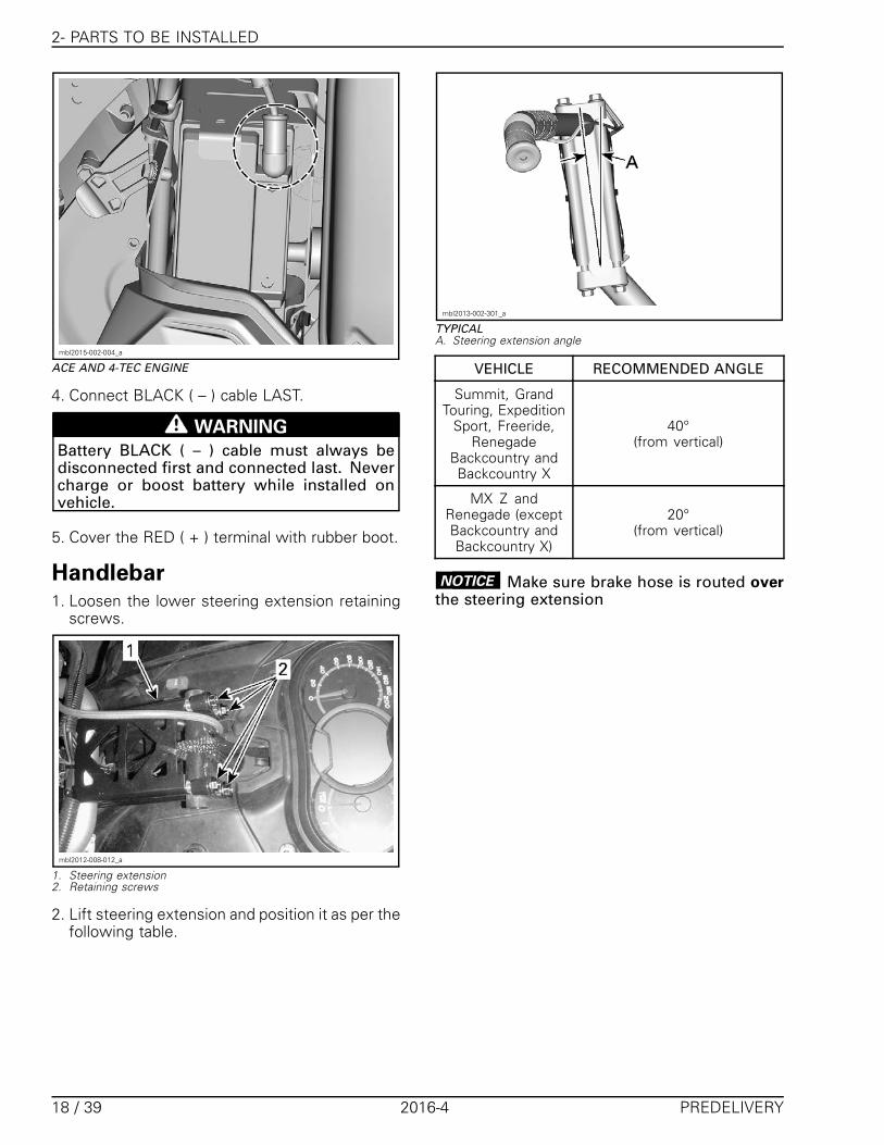
4. Connect BLACK ( – ) cable LAST.
WARNING
Battery BLACK ( – ) cable must always bedisconnected first and connected last. Nevercharge or boost battery while installed onvehicle.
5. Cover the RED ( + ) terminal with rubber boot.
Handlebar1. Loosen the lower steering extension retaining
screws.
mbl2012-008-012_a
1. Steering extension2. Retaining screws
2. Lift steering extension and position it as per thefollowing table.
mbl2013-002-301_a
TYPICALA. Steering extension angle
VEHICLE RECOMMENDED ANGLE
Summit, GrandTouring, Expedition
Sport, Freeride,Renegade
Backcountry andBackcountry X
40°(from vertical)
MX Z andRenegade (exceptBackcountry andBackcountry X)
20°(from vertical)
NOTICE Make sure brake hose is routed overthe steering extension
18 / 39 2016-4 PREDELIVERY
2- PARTS TO BE INSTALLED
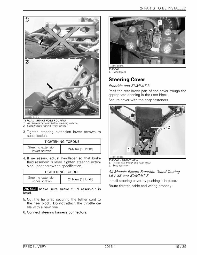
mbl2009-010-209_c
TYPICAL - BRAKE HOSE ROUTING1. As delivered (routed below steering column)2. Correct hose routing when set up
3. Tighten steering extension lower screws tospecification.
TIGHTENING TORQUE
Steering extensionlower screws 24 N•m (18 lbf•ft)
4. If necessary, adjust handlebar so that brakefluid reservoir is level, tighten steering exten-sion upper screws to specification.
TIGHTENING TORQUE
Steering extensionupper screws 24 N•m (18 lbf•ft)
NOTICE Make sure brake fluid reservoir islevel.
5. Cut the tie wrap securing the tether cord tothe riser block. Do not attach the throttle ca-ble with a new one.
6. Connect steering harness connectors.
mbl2012-008-014_a
TYPICAL1. Connectors
Steering CoverFreeride and SUMMIT XPass the rear lower part of the cover trough theappropriate opening in the riser block.Secure cover with the snap fasteners.
mbl2012-005-005_a
TYPICAL - FRONT VIEW1. Lower part trough the riser block2. Snap fasteners
All Models Except Freeride, Grand TouringLE / SE and SUMMIT XInstall steering cover by pushing it in place.Route throttle cable and wiring properly.
PREDELIVERY 2016-4 19 / 39

2- PARTS TO BE INSTALLED
mbl2013-002-006_a
TYPICAL1. Steering cover2. Throttle cable3. RH wiring
Grand Touring LE / SEInstall steering cover with screw holes towardsrear.Fasten steering cover using the 2 Torx screwssupplied in predelivery kit.
mbl2015-002-003
Handlebar Wind Deflector(Applicable Models)On each side:1. Insert arm into deflector.
msi2015-004-001_b
2. Position trim tab inside slot on deflector.
msi2015-004-002_b
3. Slide trim into place along deflector and overarm.
msi2015-004-003_b
4. Secure deflector assembly using K50 x 20 Torxscrew.
20 / 39 2016-4 PREDELIVERY

2- PARTS TO BE INSTALLED
msi2015-004-004_b
5. Cut the handlebar wiring locking ties.6. Place the arm against the handlebar.7. Install the clamp with screws but do not tighten
yet.
mbl2015-002-005_a
8. Set the deflector horizontally and tightenscrews to specification.
mbl2015-002-006_a
TIGHTENING TORQUE
Wind deflector screws 3.5 N•m (31 lbf•in)
9. Secure handlebar wiring with new locking ties.
WARNING
Turn handlebar completely from side to sidemaking sure that wind deflectors do not inter-fere with handlebar controls and accessories(throttle lever, brake lever, emergency enginestop switch, windshield, etc).
Tools and Emergency StartingRopeSecure the tools on the drive belt guard.
mbl2012-008-015
TOOL KIT
mbl2012-008-011
TOOLS STOWED
Stow the emergency starting rope in the openingon the LH of bottom pan.
mbl2012-008-016_a
1. Emergency starting rope2. Opening
PREDELIVERY 2016-4 21 / 39

2- PARTS TO BE INSTALLED
Heated Visor Extension(Expedition, Grand Touringand Renegade Enduro)1. Connect heated visor extension (predelivery kit)
to heated visor jack.
Drive Belt Installation1. Remove tether cord cap (D.E.S.S. key).2. Open LH side panel.3. Remove drive belt guard.4. Insert the driven pulley expander provided in
the tool kit in the threaded hole on the adjusterhub as shown.
mbl2011-004-001_a
1. Pulley expander
5. Open the driven pulley by screwing the tool in.6. Clean pulleys before installing drive belt using
PULLEY FLANGE CLEANER (P/N 413 711 809).7. Slip the belt over the drive pulley, then over the
driven pulley.
NOTICE Do not force or use tools to pry thebelt into place, as this could cut or break thecords in the belt.
NOTE: The maximum drive belt life span is ob-tained when belt is installed with arrows in thedirection of rotation.
mmo2011-002-006_a
TYPICAL1. To be pointed in the direction of rotation
8. Unscrew and remove the driven pulley ex-pander from the pulley.
9. Rotate the driven pulley several times to prop-erly set the belt between the sheaves.
Adjust drive belt as follows:1. Loosen the clamping screw.
mmo2011-003-010_a
1. Adjuster hub2. Clamping screw
2. Using the suspension adjustment tool providedin the tool kit, turn the ring 1/4 turn at a timethen rotate the driven pulley to properly set thebelt between the pulley sheaves.
mmo2011-003-011_a
1. Suspension adjustment tool
NOTE: The adjustment ring has left hand treads.
900 ACE and 1200 4-TEC Models withElectromechanical ReverseRepeat step 2 until the external surface of drivebelt is even with the driven pulley edge.
22 / 39 2016-4 PREDELIVERY
2- PARTS TO BE INSTALLED
mmo2012-006-906_b
TYPICAL - PRELIMINARY SETTING1. Cogs are even with pulley
Belt Without CogsRepeat step 2 until the drive belt is even with thedriven pulley edge.
mmo2012-005-981_a
PRELIMINARY SETTING1. Drive belt flush with driven pulley edge
Belt With CogsRepeat step 2 until the lowest portion of the cogson the external surface of drive belt is even withthe driven pulley edge.
mmo2012-006-905_a
TYPICAL - PRELIMINARY SETTING1. Lowest portion of cogs even with external surface of drive belt
All belt typesNOTE: Turning the ring counterclockwise lowersthe belt in the pulley. Turning the ring clockwiseraises the belt in the pulley.3. Firmly tighten the clamping screw. If
possible, tighten to 5.5 N•m ± 0.5 N•m(49 lbf•in ± 4 lbf•in) using a torque wrench.
4. Install belt guard.5. Close side panel.
NOTE: This setting is correct as a preliminary ad-justment for most models and belt types. In somecases, when starting the engine, the vehicle couldcreep, indicating that the belt is too tight.If the vehicle creeps, lower the drive belt, installbelt guard and side panel, then start engine. Re-peat until creeping stops.
Reverse ActivationNOTE: The reverse may not activate or may beharder to activate if the belt is positioned too highin the driven pulley. If reverse activation does notwork properly, ensure the drive belt is properly ad-justed. Adjust the drive belt lower in the drivenpulley if needed.
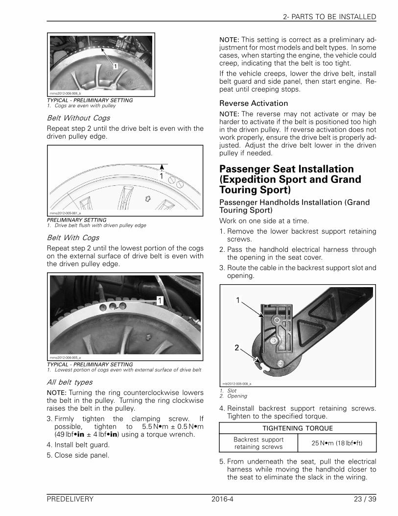
Passenger Seat Installation(Expedition Sport and GrandTouring Sport)Passenger Handholds Installation (GrandTouring Sport)Work on one side at a time.1. Remove the lower backrest support retaining
screws.2. Pass the handhold electrical harness through
the opening in the seat cover.3. Route the cable in the backrest support slot and
opening.
mbl2012-005-008_a
1. Slot2. Opening
4. Reinstall backrest support retaining screws.Tighten to the specified torque.
TIGHTENING TORQUE
Backrest supportretaining screws 25 N•m (18 lbf•ft)
5. From underneath the seat, pull the electricalharness while moving the handhold closer tothe seat to eliminate the slack in the wiring.
PREDELIVERY 2016-4 23 / 39

2- PARTS TO BE INSTALLED
6. Position the handhold on the backrest support.
mbl2012-005-009_a
1. Backrest support2. Handhold
7. Secure the handhold using the retaining plateand screw. Tighten to the specified torque.
mbl2012-005-010_a
1. Retaining plate2. Screw
TIGHTENING TORQUE
Handhold retainingscrew 25 N•m (18 lbf•ft)
8. From underneath the seat, attach connectors tothe retaining clips each side.
mbl2009-005-012_a
TYPICAL1. Clip2. Connector
9. Connect heated grip connectors to passengerseat electrical harness.
Passenger Seat Installation1. Place passenger seat over mounting holes in
tunnel.
mbl2010-003-006_a
1. Passenger seat mounting holes
2. Secure seat using the provided hardware (pre-delivery kit).– Use M6 X 30 flanged screws at rear.– Use M6 X 16 screws and washers at front.
Passenger Seat and HeatedHandholds (Grand TouringModels)1. Remove bolts and curved plates from heated
handles.
24 / 39 2016-4 PREDELIVERY

2- PARTS TO BE INSTALLED
mbl2009-005-009_a
1. Heated handle2. Bolts3. Curves plates
2. On each side of passenger seat, pull seat coverjust enough to clear wire loom holes.
mbl2009-005-010_a
1. Pull seat cover2. Wire loom hole
3. Position each handle toward front and insertelectrical connectors into wire loom holes.
NOTE: The 2 passenger heated handles have dif-ferent size connectors. Make sure you install han-dles on the proper side.
mbl2009-005-011_a
1. Insert connector
4. From under the seat, attach connectors to theretaining clips each side.
mbl2009-005-012_a
1. Clip2. Connector
5. Connect heated grips to passenger seat wireharness.
mbl2009-005-013_a
1. Passenger seat wire harness2. Heated handle connector
6. Insert handles on the rods each side of passen-ger seat and fasten with previously removedbolts and curved plates, as shown.
mbl2009-005-014_a
1. Bolts2. Curved plates3. Heated handle
Torque to 31.5 N•m (23 lbf•ft) .
PREDELIVERY 2016-4 25 / 39

2- PARTS TO BE INSTALLED
Install passenger seat:7. Put the passenger seat behind the driver's seat.
Let enough space between the seats to con-nect the accessories connector.
mbl2009-005-015_a
1. Accessories connector (behind driver's seat)2. Accessories connector (passenger seat)
8. Slightly incline the passenger seat towardsfront and engage seat hooks in the tunnel slotslocated behind the driver's seat.
mmo2009-005-013 _a
1. Driver's seat2. Tunnel slot
9. Push the front portion of the passenger seat to-wards the driver's seat and firmly push the rearportion down to lock the passenger seat in po-sition.
NOTE: A distinctive snap will be felt. Doublecheck that the seat is secure by giving it a tug toconfirm proper latching.
Tunnel Bag (Grand Touring SE)Secure to the rack using the hook and loops strapsas shown.
msi2009-085-002_a
1. Velcro strap2. Rear rack
The retaining hook and loops straps can be hiddenin side pouches. The side pouches flaps are hid-den in the bottom lining of the tunnel bag.
Saddlebags (Grand Touring SE)1. Insert the metal tabs, located on the rear
bumper, in the saddlebag slots.2. Firmly push the top of the saddlebag towards
the vehicle. A "snap" will be felt when the sad-dlebag is properly secured. Make sure the sad-dle bags are properly secured before getting un-derway.
msi2009-029-012_b
Step 1: Insert tabsStep 2: Push towards vehicle
Hitch (Expedition Sport andGrand Touring Sport Europe)Install hitch using the mounting holes in the rearbumper.
TIGHTENING TORQUE
Hitch bolts 31 N•m (23 lbf•ft)
26 / 39 2016-4 PREDELIVERY

2- PARTS TO BE INSTALLED
Snow GuardFrom underneath the rear portion of tunnel, re-move screws securing tail light.Secure the snow guard using the 3/16 pop rivetsand washers (predelivery kit).Reinstall previously removed screws.
TIGHTENING TORQUE
Tail light retaining screws 0.4 N•m (4 lbf•in)
Rear Bumper1. Align holes of rear bumper with frame holes.
Standard Bumper2. Secure rear bumper to frame using M6 x 16
Torx screws (predelivery kit).
mbl2015-006-003
25.4 MM (1 IN) HEIGHT BUMPER SECTION
Heavy-Duty Bumper3. Secure rear bumper to frame using M6 x 18
Torx screws and washers (predelivery kit).
mbl2015-006-004
42 MM (1-21/32 IN) HEIGHT BUMPER SECTION
4. Tighten screws to specification.
TIGHTENING TORQUE
Rear bumper screws 16 N•m (142 lbf•in)
Side ReflectorsApply reflectors on both sides. Make sure theyare visible.
fmbl2013_002_002_a
TYPICAL REFLECTOR INSTALLATION1. LH reflector
Front Reflector (EuropeanModels)1. Using the following information, drill two holes
of 4.5 mm (3/16 in) through the bottom pancover.
mbl2013-002-200_a
A. 20 mm (25/32 in)
mbl2013-002-201_a
A. 30 mm (1-3/16 in)
PREDELIVERY 2016-4 27 / 39

2- PARTS TO BE INSTALLED
mbl2013-002-204
2. Insert locking ties in the reflector support slotsas shown.
mbl2011-003-002
3. Install the reflector support on vehicle. Makesure locking ties are installed tightly so that theydon't exceed the support recesses.
mbl2013-002-202_a
4. Clean reflector support with isopropyl alcoholand stick the reflector on the support.
mbl2013-002-203
Other Models1. Insert locking ties in the reflector support slots
as shown.
mbl2011-003-002
2. Place the reflector support centered on thefront bumper, then attach the locking ties.
mbl2011-003-003
3. Install the locking ties tightly so that they don'texceed the support recesses.
28 / 39 2016-4 PREDELIVERY

3- FLUIDS
mbl2011-003-004_a
LOCKING TIE INCORRECTLY TIGHTENED
mbl2011-003-005
LOCKING TIE CORRECTLY TIGHTENED (NOT EXCEEDINGRECESSES)
4. Stick the reflector on the support.Make sure the support is still centered on thebumper.
Snowboard and Ski Rack(Summit Burton Model)To install the snowboard and ski rack providedwith the vehicle, refer to the instruction sheet(P/N 487 801 810) included in the kit, or on Knowl-edge Center.
tbl2015-004-003_a
3- FLUIDSGeneral GuidelinesAll fluids (except fuel) have already been filled atfactory, it is only necessary to check the levels.However, if refill is needed, refer to the appropri-ate Ski-Doo SHOP MANUAL for the proper proce-dure.
FuelRecommended FuelUse unleaded gasoline containing MAXIMUM10% ethanol. The gasoline must have the follow-ing minimum octane requirements.
FUELTYPE
ENGINEMIN. OCTANE
RATING
600 ACE900 ACE
1200 4-TEC
87 AKI(RON+MON)/2
92 RONFuelwith NOethanol 600 HO E-TEC
800R E-TEC
91 AKI(RON+MON)/2
95 RON
Fuelwhichmay
containup to10%MAX
ethanol
600 ACE900 ACE
600 HO E-TEC800R E-TEC1200 4-TEC
91 AKI(RON+MON)/2
95 RON
PREDELIVERY 2016-4 29 / 39

3- FLUIDS
NOTICE Never experiment with other fuels.Engine or fuel system damages may occurwith the use of an inadequate fuel.
Fuel Antifreeze AdditivesWhen using oxygenated fuel, additional gas lineantifreeze or water absorbing additives are not re-quired and should be not used.When using non-oxygenated fuel, we highlyrecommend the use of isopropyl base gas lineantifreeze in a proportion of 150 ml (5 U.S. oz) ofgas line antifreeze added to 40 L (10.6 U.S. gal.)of gas.This precaution is in order to reduce the risk offrost buildup in fuel system components whichmay lead, in certain cases, to severe damage toengine.NOTE: Use only methyl hydrate free gas line an-tifreeze.
Engine CoolantRecommended CoolantThe cooling system can be filled with distilled wa-ter and antifreeze solution (50% distilled water,50% antifreeze).
NOTICE Always use ethylene-glycol an-tifreeze containing corrosion inhibitors specif-ically for internal combustion aluminum en-gines.
For best performance, use the following recom-mended product.
RECOMMENDED ANTIFREEZE
Finland, Norway and SwedenLONG LIFE
ANTIFREEZE(F)(P/N 619 590 204)
All Other CountriesLONG LIFE
ANTIFREEZE(P/N 219 702 685)
Coolant Level VerificationCheck coolant level at room temperature with thecap removed.Liquid should be at cold level line (engine cold) ofcoolant tank.NOTE: When checking level at low temperature itmay be slightly lower then the mark.Add if necessary.
mbl2013-002-015_a
1. COLD LEVEL line
Chaincase OilRecommended Chaincase Oil
RECOMMENDED CHAINCASE OIL
XPS SYNTHETIC CHAINCASE OIL (P/N 413 803 300)
Chaincase Oil Level Verification1. With the vehicle on a level surface, check the
oil level by removing the check plug on the leftside of chaincase. Oil level must be equal withthe lower edge.
mmo2011-003-017_a
TYPICAL - 600 ACE, 900 ACE AND 1200 4-TEC MODELS1. Check plug
30 / 39 2016-4 PREDELIVERY

3- FLUIDS
mmr2008-047-002_a
TYPICAL - 600HO E-TEC MODELS AND 800R E-TEC1. Check plug
To add oil, remove the filler cap on chaincasecover.
mbl2009-010-204_a
TYPICAL1. Filler cap
2. Pour recommended oil in chaincase by the fillerhole until oil comes out by the check plug hole.
CHAINCASE OIL CAPACITY
600 HO ETEC and800R E-TEC Models 350 ml (12 U.S. oz)
600 ACE, 900 ACE and1200 4-TEC Models 500 ml (17 U.S. oz)
Reinstall check plug and torque to specification.
CHECK PLUG TORQUE
6 N•m (53 lbf•in)
Injection OilRecommended OilAlways maintain a sufficient amount of recom-mended injection oil in the injection oil reservoir.
WARNING
Do not overfill. Reinstall cap and fullytighten. Wipe off any oil spills. Oil is highlyflammable when heated.
RECOMMENDED INJECTION OIL
XPS SYNTHETIC 2-STROKE OIL(P/N 293 600 132)
NOTICE The engine of this snowmobile hasbeen developed and validated using the rec-ommended BRP XPS oil. BRP strongly recom-mends the use of its recommended XPS oil atall times. Damages caused by oil which is notsuitable for the engine will not be covered bythe BRP limited warranty.
Brake Fluid LevelRecommended Brake Oil
RECOMMENDED BRAKE OIL
BRAKE FLUID GTLMA DOT4 (P/N 293 600 131)
Brake Oil Level Verification1. Check brake fluid in reservoir for proper level.2. Add brake fluid as required.
WARNING
Use only DOT 4 brake fluid from a sealed con-tainer. To avoid serious damage to the brak-ing system, do not use fluids other than therecommended one, nor mix different fluidsfor topping up.
NOTICE Brake fluid can damage painted andplastic parts. Handle with care. Rinse thor-oughly in case of spillage.
PREDELIVERY 2016-4 31 / 39

4- UPPER BODY MODULE INSTALLATION
mmo2008-008-018_a
1. Minimum2. Maximum3. Operating range
Engine Oil (600 ACE, 900 ACEand 1200 4-TEC)Recommended Engine Oil
RECOMMENDED ENGINE OIL
XPS 4-STROKE SYNTHETIC OIL (ALL CLIMATE)(P/N 293 600 112)
NOTICE The engine of this snowmobile hasbeen developed and validated using the rec-ommended BRP XPS™ oil. BRP strongly rec-ommends the use of its recommended XPS oilat all times. Damages caused by oil which isnot suitable for the engine will not be coveredby the BRP limited warranty.
If the recommended oil is not available, use SAE0W-40 synthetic-based oil that meets or exceedsthe requirements for API service classificationSM.
Engine Oil Level Verification
NOTICE Check level every 10 hours of use andrefill if necessary. Do not overfill. Operatingthe engine with an improper level may se-verely damage engine. Wipe off any spillage.
Make sure the engine is at normal operating tem-perature.NOTE: The engine reaches normal temperaturewhen the rear radiator gets warm indicating thethermostat has opened.Place vehicle on a level surface and proceed asfollows to check oil level:1. Let engine run at idle for approximately 30 sec-
onds.
2. Stop engine.3. Open the LH side panel, refer to CONTROLS,
INSTRUMENTS AND EQUIPMENT.4. Remove the drive belt guard, refer to CON-
TROLS, INSTRUMENTS AND EQUIPMENT.5. Remove dipstick from the filler tube, then wipe
it clean.6. Completely insert dipstick in the filler tube.7. Remove dipstick and check the oil level. Oil
level should be between the MIN. and MAX.marks as shown, add if necessary.
�
����
����
mmo2009-005-027_a
1. Oil level between MIN. and MAX.
WARNING
Wipe off any oil spills. Oil is highlyflammable when heated.
4- UPPER BODY MODULEINSTALLATION1. Insert the upper body module tabs into the up-
per bottom pan openings.
mbl2012-008-009_a
2. Slide the module towards rear.
32 / 39 2016-4 PREDELIVERY

4- UPPER BODY MODULE INSTALLATION
mbl2013-002-011_b
3. On both sides, install the upper body moduleretaining screws.
mbl2013-002-010_a
RH SIDE SHOWN1. Retaining screws
4. Connect:– APS hose on the ECM– Headlights connector– Gauge connector– Air temperature sensor (ATS)– Air intake connector tube.
5. Install:– Gauge– Drive belt guard.
6. Install side panels
Front Storage CompartmentCoverSnap cover in place.
mbl2013-002-007_a
mbl2015-002-011_a
Console Wind Deflectors (ifEquipped)
mbl2013-002-014_a
PREDELIVERY 2016-4 33 / 39
5- SET-UP
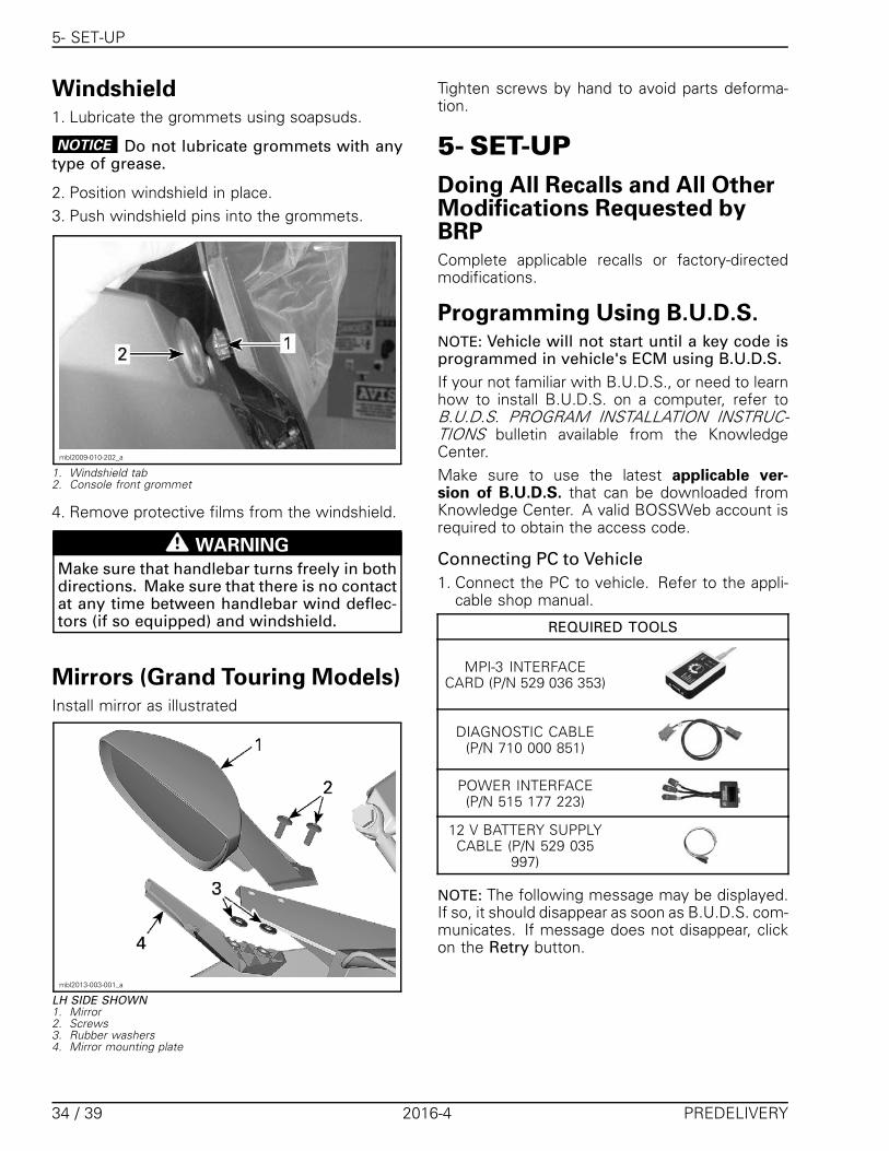
Windshield1. Lubricate the grommets using soapsuds.
NOTICE Do not lubricate grommets with anytype of grease.
2. Position windshield in place.3. Push windshield pins into the grommets.
mbl2009-010-202_a
1. Windshield tab2. Console front grommet
4. Remove protective films from the windshield.
WARNING
Make sure that handlebar turns freely in bothdirections. Make sure that there is no contactat any time between handlebar wind deflec-tors (if so equipped) and windshield.
Mirrors (Grand Touring Models)Install mirror as illustrated
mbl2013-003-001_a
LH SIDE SHOWN1. Mirror2. Screws3. Rubber washers4. Mirror mounting plate
Tighten screws by hand to avoid parts deforma-tion.
5- SET-UPDoing All Recalls and All OtherModifications Requested byBRPComplete applicable recalls or factory-directedmodifications.
Programming Using B.U.D.S.NOTE: Vehicle will not start until a key code isprogrammed in vehicle's ECM using B.U.D.S.If your not familiar with B.U.D.S., or need to learnhow to install B.U.D.S. on a computer, refer toB.U.D.S. PROGRAM INSTALLATION INSTRUC-TIONS bulletin available from the KnowledgeCenter.Make sure to use the latest applicable ver-sion of B.U.D.S. that can be downloaded fromKnowledge Center. A valid BOSSWeb account isrequired to obtain the access code.
Connecting PC to Vehicle1. Connect the PC to vehicle. Refer to the appli-
cable shop manual.
REQUIRED TOOLS
MPI-3 INTERFACECARD (P/N 529 036 353)
DIAGNOSTIC CABLE(P/N 710 000 851)
POWER INTERFACE(P/N 515 177 223)
12 V BATTERY SUPPLYCABLE (P/N 529 035
997)
NOTE: The following message may be displayed.If so, it should disappear as soon as B.U.D.S. com-municates. If message does not disappear, clickon the Retry button.
34 / 39 2016-4 PREDELIVERY

5- SET-UP
mbl2014-006-300
2. Make sure status bar shows proper Protocol.
�������
����
CONNECTION SUCCESSFUL
NOTE: Number 2 indicates that the ECM and themultifunction gauge are recognized by the MPI.On models equipped with a THCM, a "3" will bedisplayed.If an “X” or a “1”is shown instead of a “2” or "3",it means that there is no communication betweenMPI and ECM and/or multifunction gauge. Possi-ble causes are:– ECM and/or multifunction gauge not powered– Bad connection between MPI and ECM and/or
multifunction gauge.3. Press Read Data button to download data from
the vehicle.
vdd2006-001-101
Programing Keys with B.U.D.S.1. Install new key to be programmed on vehicle
D.E.S.S. post.2. Click on Keys tab.
smr2005-072-001_en
NOTE: When programing a vehicle for the firsttime, you need to click on Erase All Keys button.3. Click on Add Key.
smr2005-072-003_Aen
1. Add Key
4. Click on Write Data to save a new key in vehi-cle's ECM.
vmr2006-012-100_ben
A new key is now saved in computer.5. Repeat to program more keys.
Speedometer Setting (Miles orKilometers)Speedometer is factory preset in miles. Dealerneeds to use B.U.D.S. to change it to kilometers.Select Setting and Clustertabs.In the Cluster Units box:– For kilometers select Metric– For miles select Imperial.
PREDELIVERY 2016-4 35 / 39

5- SET-UP
Ending a B.U.D.S. Session1. Click on Faults tab and check if there are ac-
tive fault codes. If so, service vehicle then clearfault codes in B.U.D.S.
NOTICE After a problem has been solved,ensure to clear fault code(s) in ECM. This willproperly reset appropriate counter(s). Thiswill also record that problem has been fixed inECM memory.
2. Click on Write Data button to transfer new set-tings and information to ECM.
3. Click on Exit button (right most) to end session.4. Ensure to reinstall communication connector in
its cover.
TrackTrack Tension Adjustment and Alignment1. Remove the D.E.S.S. key (tether cord cap).2. Lift rear of vehicle and support it off the ground.3. Allow rear suspension to fully extend.4. Loosen one of the rear axle retaining screws (3
and 4 idler wheels system).
mbl2015-002-010_a
3 AND 4 IDLER WHEELS SYSTEM
5. Loosen rear axle retaining nut and screw (2 idlerwheels system).
mbl2015-002-009_a
2 IDLER WHEELS SYSTEM
6. Tighten both adjustment screws equally to in-crease track tension a little.
mbl2015-002-010_b
3 AND 4 IDLER WHEELS SYSTEM
mbl2015-002-009_b
2 IDLER WHEELS SYSTEM
7. Use the TENSIOMETER (P/N 414 348 200).
36 / 39 2016-4 PREDELIVERY

5- SET-UP
414348200
8. Set deflection between using bottom O-ring.
BOTTOM O-RING SETTING
Expedition Sport 4.2 cm (1-5/8 in)
All others 3.2 cm (1-1/4 in)
mmr2009-133-003_b
DEFLECTION SETTING1. Bottom O-ring
9. Place upper O-ring to 0 kgf (0 lbf).10. Position the tensiometer on track, halfway be-
tween front and rear idler wheels.11. Push the tensiometer downwards until bot-
tom O-ring (deflection set earlier) be alignedwith the bottom of slider shoe.
mmr2009-133-001_a
mmr2009-133-002_a
1. Deflection O-ring aligned with slider shoe
12. Read load recorded by the upper O-ring on thetensiometer.
mmr2009-133-003_a
LOAD READING1. Upper O-ring
13. Load reading must be as per the following ta-ble.
TRACK ADJUSTMENT SPECIFICATION
Track deflection setting(Expedition Sport) 4.2 cm (1-5/8 in)
Track deflection setting(All others) 3.2 cm (1-1/4 in)
Track load reading 6 kg to 8.5 kg(13 lb to 19 lb)
14. Tighten or loosen both adjustment screws un-til specified tension is obtained.
15. Tighten rear idler wheel fasteners.
TIGHTENING TORQUE
Rear idler wheelretaining screws (3 and4 idler wheels system)
48 N•m ± 6 N•m(35 lbf•ft ± 4 lbf•ft)
Rear idler wheelretaining nut and screw(2 idler wheels system)
24.5 N•m ± 3.5 N•m(18 lbf•ft ± 3 lbf•ft)
Check track alignment as follows:16. Start engine and accelerate slightly so that
track slowly turns. This must be done in ashort period of time (15 to 20 seconds).
17. Check that the track is well centered; equaldistance on both sides between edges oftrack guides and slider shoes.
A01F05A
1
2
3
1. Guides2. Slider shoes3. Equal distance
18. To correct track alignment:18.1 Stop engine.
PREDELIVERY 2016-4 37 / 39
6- ADJUSTMENTS (CUSTOMER PREFERENCE)
18.2 Remove D.E.S.S. key (tether cord cap)18.3 Loosen one of the rear wheel retaining
screws (3 and 4 idler wheels system).18.4 Loosen rear axle retaining nut (2 idler
wheels system).18.5 Tighten adjustment screw on the side
where the slider shoe is the farthestfrom the track insert guides.
19. Tighten rear idler wheel fasteners.
TIGHTENING TORQUE
Rear idler wheelretaining screws (3 and4 idler wheels system)
48 N•m ± 6 N•m(35 lbf•ft ± 4 lbf•ft)
Rear idler wheelretaining nut and screw(2 idler wheels system)
24.5 N•m ± 3.5 N•m(18 lbf•ft ± 3 lbf•ft)
20. Repeat procedure until alignment is correct.Recheck tension.
Track Studding
WARNING
Never stud a track that has not been ap-proved for studs. Installing studs on anunapproved track could increase risks oftrack tearing or severing, possibly resultingin serious injuries or death.
WARNING
For track studding, always refer to the IN-STRUCTION SHEET supplied with stud kitsthat are APPROVED by BRP for models cov-ered in this PREDELIVERY BULLETIN.
1. Install wheel caps (predelivery kit).NOTE: If lubricant is needed to help cap installa-tion, use glass cleaner instead of soapy water toavoid cap to get out from its location due to soapresidue.
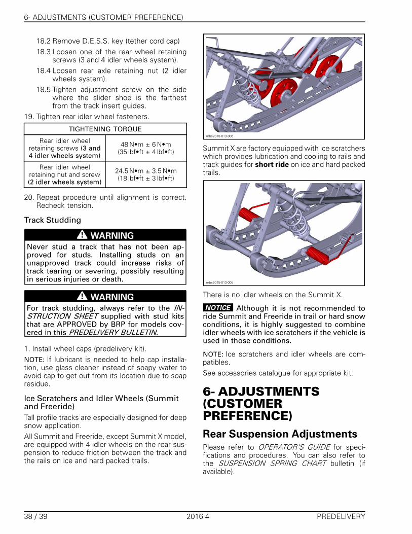
Ice Scratchers and Idler Wheels (Summitand Freeride)Tall profile tracks are especially designed for deepsnow application.All Summit and Freeride, except Summit X model,are equipped with 4 idler wheels on the rear sus-pension to reduce friction between the track andthe rails on ice and hard packed trails.
mbs2015-013-006
Summit X are factory equipped with ice scratcherswhich provides lubrication and cooling to rails andtrack guides for short ride on ice and hard packedtrails.
mbs2015-013-005
There is no idler wheels on the Summit X.
NOTICE Although it is not recommended toride Summit and Freeride in trail or hard snowconditions, it is highly suggested to combineidler wheels with ice scratchers if the vehicle isused in those conditions.
NOTE: Ice scratchers and idler wheels are com-patibles.See accessories catalogue for appropriate kit.
6- ADJUSTMENTS(CUSTOMERPREFERENCE)Rear Suspension AdjustmentsPlease refer to OPERATOR'S GUIDE for speci-fications and procedures. You can also refer tothe SUSPENSION SPRING CHART bulletin (ifavailable).
38 / 39 2016-4 PREDELIVERY

7- FINAL INSPECTION
7- FINAL INSPECTIONControls, Equipments,Movement and OperationInspection1. Make sure the following controls and equip-
ments are fully operational:– Throttle, brake and parking brake levers– Ignition, emergency stop switch and tether
stop switch– Headlights, taillight and brake light– Steering system.
2. Fasteners tightening torque recheck:– Ski nuts– Shock absorber nuts– Handlebar nuts.
3. Ensure that hang tag is on vehicle handlebars.4. Ensure TOOL KIT and OPERATOR’S GUIDE are
in the vehicle.
Test Run Snowmobile1. Test ride vehicle.
Snowmobile Cleaned and inShowroom Condition1. Make sure all protective wrapping is removed
from vehicle.2. Wash and dry vehicle. Use XPS ATV WASH
(P/N 219 701 702).
NOTICE Never use a high pressure washer toclean vehicle. High pressure can cause electri-cal or mechanical damages.
For stubborn dirt on vinyl or plastic parts, usingflannel or micro-fibre towels with XPS ALL PUR-POSE CLEANER (P/N 219 701 709).
NOTICE It is necessary to use flannel or micro-fiber clothes on plastic parts to avoid scratch-ing the surfaces. Never clean plastic parts withstrong detergent, paint thinner, acetone, prod-ucts containing chlorine, petroleum, etc.
Vehicle DeliveryComplete PREDELIVERY CHECK LIST.Give the OPERATOR’S GUIDE and the SAFETYDVD to the customer.Customer must read and sign the PREDELIVERYCHECK LIST.
Hang tag is to be removed by the owner only.Any person who rides this vehicle should read andunderstand all the information given on hang tagand safety labels before riding.
PREDELIVERY 2016-4 39 / 39