principles for tunnel design 20th to 21st april 2017 kuala ... · pdf fileherrenknecht asia...
TRANSCRIPT
Principles for Tunnel Design
20th to 21st April 2017– Kuala Lumpur
Mechanized Tunneling (TBM and Support Systems) Thorsten Tatzki
Herrenknecht Asia Headquarters Pte. Ltd.

2 Principles for Tunnel Design 20th to 21st April 2017– Kuala Lumpur
Introduction: General Overview
Shield Machines and Tunnel Boring Machines
Slurry Shield/Mixshield
Gripper TBM Single Shield TBM Double Shield TBM
EPB Shield Multi-mode TBM
3 Principles for Tunnel Design 20th to 21st April 2017– Kuala Lumpur
Outline of Lecture
Selection of Tunnelling Machines
DAUB Classification Scheme
Geotechnics
Lining / Support
Influencing Aspects
Key Elements of Machine Design
Mechanized Tunnelling for Rock
Gripper
Single Shield
Double Shield
Mechanized Tunnelling for Soil Conditions
Earth Pressure Balance Shield Machines
Slurry Shield Machine / Mixshield Machines
Multi Mode Machines
Important Technical Trends
Literature / Links

4 Principles for Tunnel Design 20th to 21st April 2017– Kuala Lumpur
Selection of Tunnelling Machines
5 Principles for Tunnel Design 20th to 21st April 2017– Kuala Lumpur
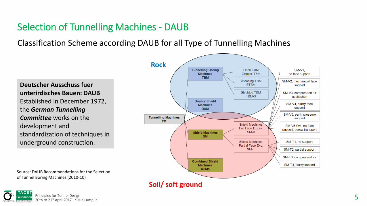
Classification Scheme according DAUB for all Type of Tunnelling Machines
Rock
Soil/ soft ground
Source: DAUB Recommendations for the Selection of Tunnel Boring Machines (2010-10)
Deutscher Ausschuss fuer unterirdisches Bauen: DAUB Established in December 1972, the German Tunnelling Committee works on the development and standardization of techniques in underground construction.
Selection of Tunnelling Machines - DAUB

6 Principles for Tunnel Design 20th to 21st April 2017– Kuala Lumpur
Selection of Tunnelling Machines - Geotechnics
General information:
Geological longitudinal profile with vertical alignment of the tunnel (max./min. gradient) and borehole locations
Layer structure & Groundwater conditions (max./min. groundwater pressure during construction)
Horizontal alignment (max./min. radius) of the tunnel with borehole locations
Details about the soil layers:
Grain size distribution curves
Specific weights / ’
Shear parameters: , c, cu
Permeability k
In case of fine soil: clay mineralogy and consistency (Atterberg Limits)
In case of granular soil: Quartz content
Modulus of elasticity Es
Possible existence of boulders: rock type, expected amount, expected sizes, UCS, quartz content, CAI
In situ stress situation:
Earth pressure coefficient K0

7 Principles for Tunnel Design 20th to 21st April 2017– Kuala Lumpur
Selection of Tunnelling Machines – Lining / Support
Methods of supporting the ground and holding water at the face Source: Mechanised Shield Tunnelling
Possible types of lining in shield tunnelling Source: Mechanised Shield Tunnelling
8 Principles for Tunnel Design 20th to 21st April 2017– Kuala Lumpur
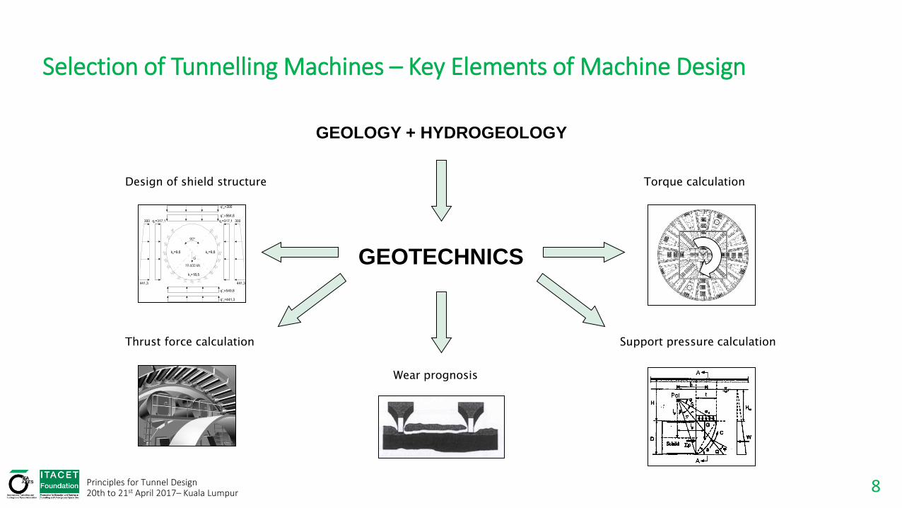
Selection of Tunnelling Machines – Key Elements of Machine Design
Design of shield structure
Support pressure calculation
Torque calculation
Thrust force calculation
Wear prognosis
GEOTECHNICS
GEOLOGY + HYDROGEOLOGY

9 Principles for Tunnel Design 20th to 21st April 2017– Kuala Lumpur
Selection of Tunnelling Machines – Key Elements of Machine Design
Interface Ground & TBM: support pressure
t
R
G
S
SCHILD
GOK
p(t)
D
b
R
G
90
E
F
E
G
F+K
R
K
SILO
ERDKEIL
z1
tw
pLPz2
GW
p(t)
Some important questions:
Where is highest overburden?
Where is highest water level above crown?
Where are the highest surface loads?
Lowest inner friction angle?
Lowest cohesion?
Foundation loads?

10 Principles for Tunnel Design 20th to 21st April 2017– Kuala Lumpur
Selection of Tunnelling Machines – Key Elements of Machine Design
Interface Ground & TBM Shield Loads
Vertical earth pressure (crown)
G
k = 6 MN/m3
Vertical water pressure (crown)
Vertical earth pressure (invert)
Vertical earth pressure (invert)
Horizontal earth pressure
Horizotal water pressure
External loads:
Water and earth pressure
Rock burst, Swelling pressure, Squeezing pressure
Steering movements
Buoyancy
Internal loads:
Pressure on bulk head
Thrust forces
Erector and ring built
Weight of the components (drive, bridge … )
Grease pressure (tail skin sealing)

11 Principles for Tunnel Design 20th to 21st April 2017– Kuala Lumpur
Selection of Tunnelling Machines – Key Elements of Machine Design
Friction of the shield coat MW 5,0 2 HVlr
Thrust resistance of cutting edge schW tpr sch 2
Cutterhead thrust
Drag force tailskin seal SSWF sTübbing PD *
Drag force back-up system
Support pressure
Force of thrust cylinders W SPNLSBASchM FFFWWW
BAW maximum tool thrust or thrust of displacement cylinders
NLF empirical value
SPF support pressure calculation
G
FSP WM
WBA WNL
Interface Ground & TBM Thrust Force

12 Principles for Tunnel Design 20th to 21st April 2017– Kuala Lumpur
Selection of Tunnelling Machines – Key Elements of Machine Design
Weak rock:
High penetration
Large “crushing zone”
with low thrust and
small angle
Hard rock:
Low penetration
Small “crushing zone”
with high thrust and
large angle
Interface Ground & Wear and Performance

13 Principles for Tunnel Design 20th to 21st April 2017– Kuala Lumpur
Mechanized Tunnelling for Rock
14
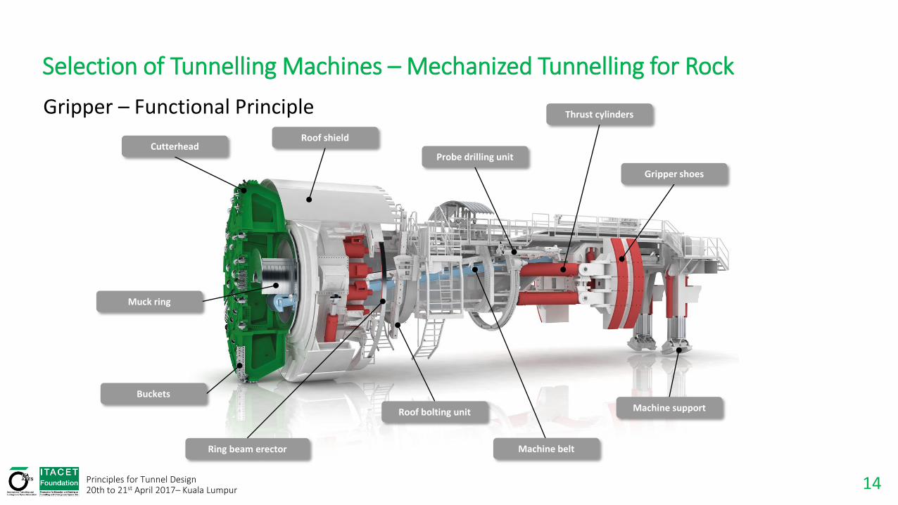
Selection of Tunnelling Machines – Mechanized Tunnelling for Rock
Machine belt
Machine support
Cutterhead
Muck ring
Buckets
Roof shield
Probe drilling unit
Thrust cylinders
Gripper shoes
Ring beam erector
Roof bolting unit
Gripper – Functional Principle
Principles for Tunnel Design 20th to 21st April 2017– Kuala Lumpur

15 Principles for Tunnel Design 20th to 21st April 2017– Kuala Lumpur
Selection of Tunnelling Machines – Mechanized Tunnelling for Rock
Double Gripper TBM: S-96 TBM 3000, 3.00m
Single Gripper TBM: S-155 Tscharner, 9.53m
Double Shield TBM: S-153 La Réunion, 3.80m
Shielded TBM with articulation joint: S- 163 Sörenberg, 4.56m
Overview of the various machine systems of TBM with full face excavation Source: Hardrock Tunnel Boring Machines, 2008
16
1 2
3 4
5
6
7
Principles for Tunnel Design 20th to 21st April 2017– Kuala Lumpur
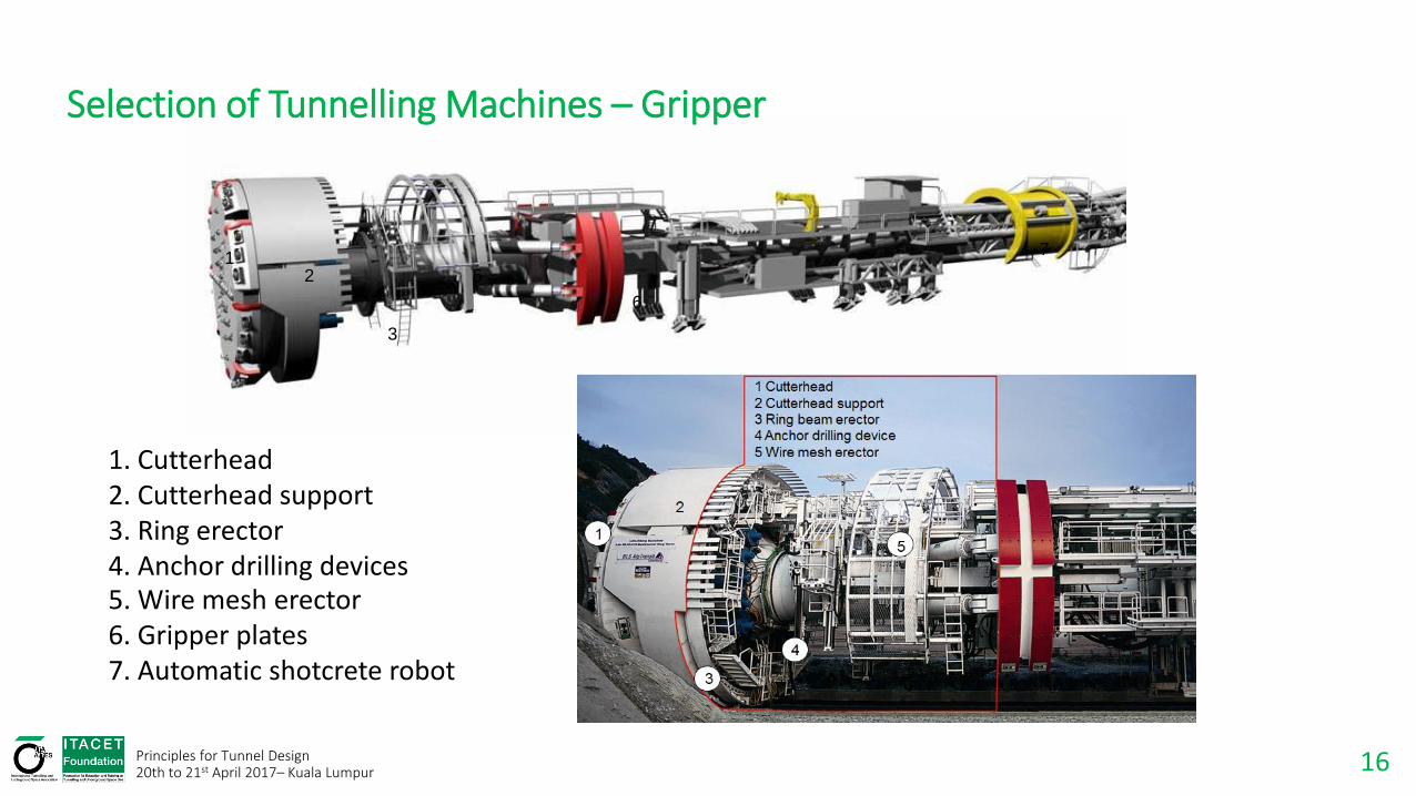
Selection of Tunnelling Machines – Gripper
5. Wire mesh erector 6. Gripper plates 7. Automatic shotcrete robot
1. Cutterhead 2. Cutterhead support 3. Ring erector 4. Anchor drilling devices

17 Principles for Tunnel Design 20th to 21st April 2017– Kuala Lumpur
Selection of Tunnelling Machines – Gripper / Mucking

18 Principles for Tunnel Design 20th to 21st April 2017– Kuala Lumpur
Selection of Tunnelling Machines – Gripper / Cutting Wheel
Wear protection measures on cutterhead for blocky face conditions
Hardox-plates on entire surface
Protection blocks for cutter discs
Grain size limiters for buckets
Heavy bucket lips
Overcutting with shifting Gauge Cutter

19 Principles for Tunnel Design 20th to 21st April 2017– Kuala Lumpur
Selection of Tunnelling Machines – Gripper / Tunnel Support

20 Principles for Tunnel Design 20th to 21st April 2017– Kuala Lumpur
Selection of Tunnelling Machines – Gripper / Probe Drilling
Gripper TBM. Tunnel support in working area L1
Exploration Drilling
Drainage and Injection
Core Sampling
Geological Investigations
21 Principles for Tunnel Design 20th to 21st April 2017– Kuala Lumpur
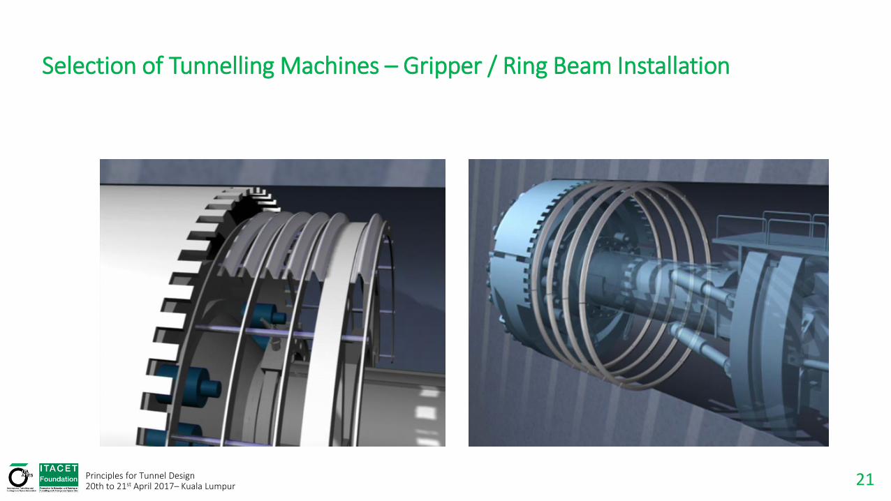
Selection of Tunnelling Machines – Gripper / Ring Beam Installation
22 Principles for Tunnel Design 20th to 21st April 2017– Kuala Lumpur
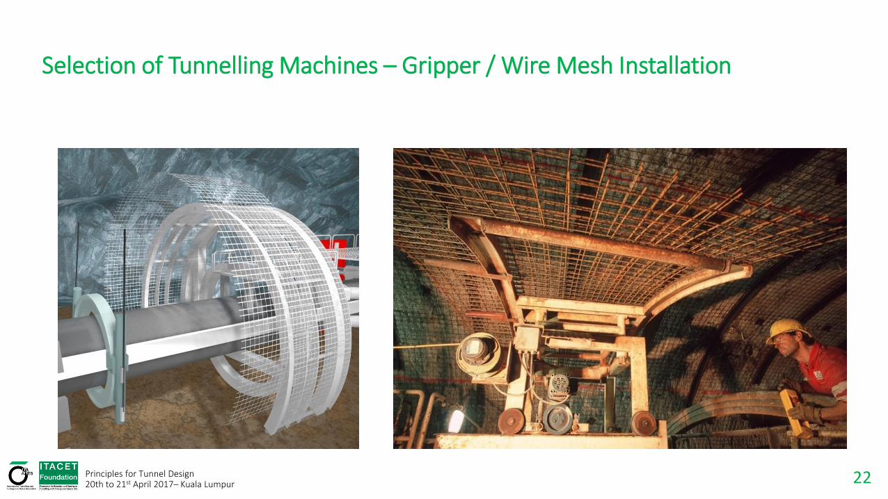
Selection of Tunnelling Machines – Gripper / Wire Mesh Installation
23 Principles for Tunnel Design 20th to 21st April 2017– Kuala Lumpur
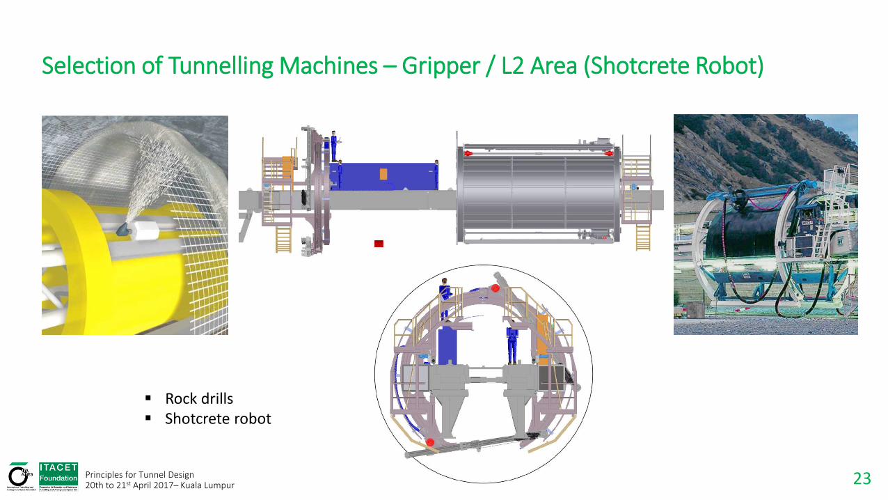
Selection of Tunnelling Machines – Gripper / L2 Area (Shotcrete Robot)
Rock drills Shotcrete robot
24 Principles for Tunnel Design 20th to 21st April 2017– Kuala Lumpur
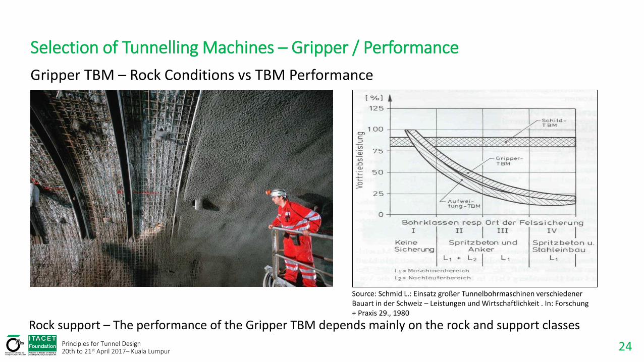
Selection of Tunnelling Machines – Gripper / Performance
Rock support – The performance of the Gripper TBM depends mainly on the rock and support classes
Source: Schmid L.: Einsatz großer Tunnelbohrmaschinen verschiedener Bauart in der Schweiz – Leistungen und Wirtschaftlichkeit . In: Forschung + Praxis 29., 1980
Gripper TBM – Rock Conditions vs TBM Performance
25 Principles for Tunnel Design 20th to 21st April 2017– Kuala Lumpur
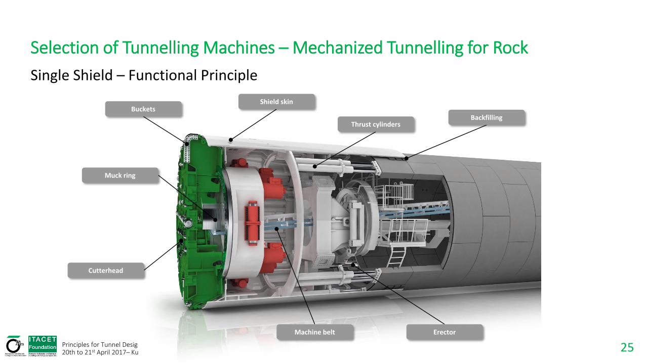
Selection of Tunnelling Machines – Mechanized Tunnelling for Rock
Cutterhead
Muck ring
Buckets Shield skin
Thrust cylinders Backfilling
Machine belt Erector
Single Shield – Functional Principle
26 Principles for Tunnel Design 20th to 21st April 2017– Kuala Lumpur
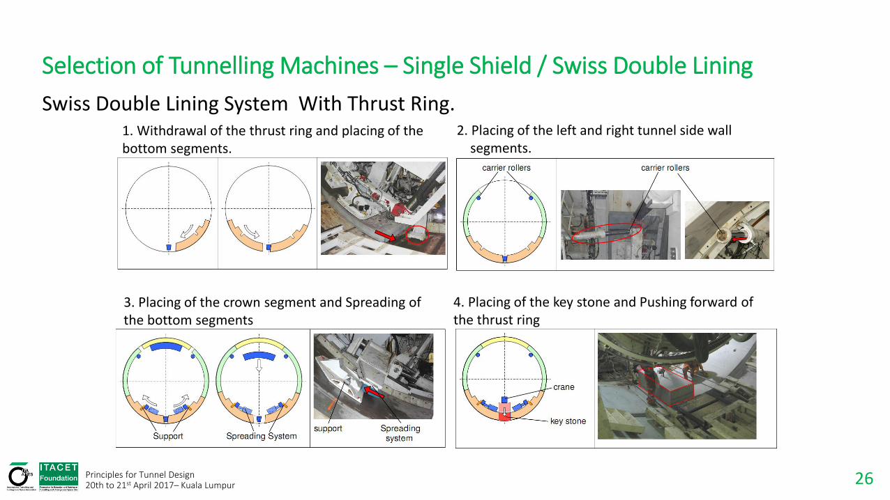
Selection of Tunnelling Machines – Single Shield / Swiss Double Lining
1. Withdrawal of the thrust ring and placing of the bottom segments.
2. Placing of the left and right tunnel side wall segments.
3. Placing of the crown segment and Spreading of the bottom segments
4. Placing of the key stone and Pushing forward of the thrust ring
Swiss Double Lining System With Thrust Ring.
27 Principles for Tunnel Design 20th to 21st April 2017– Kuala Lumpur
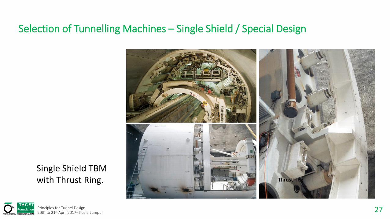
Selection of Tunnelling Machines – Single Shield / Special Design
Thrust ring
Swing support roller
Single Shield TBM with Thrust Ring.

28
Selection of Tunnelling Machines – Mechanized Tunnelling for Rock
Muck ring
Cutterhead
Front shield
Stabilizers
Telescopic shield
Gripper shield
Gripper shoes
Erector
Torque cylinders
Main thrust cylinders
Machine belt
Auxiliary thrust cylinders
Double Shield – Functional Principle
Principles for Tunnel Design 20th to 21st April 2017– Kuala Lumpur

29 Principles for Tunnel Design 20th to 21st April 2017– Kuala Lumpur
Selection of Tunnelling Machines – Double Shield / Telescopic Shield
Thrust cylinders Open telescope

30 Principles for Tunnel Design 20th to 21st April 2017– Kuala Lumpur
Selection of Tunnelling Machines – Double Shield / Logistic
DOUBLE-SHIELD
Tunnelling
Ring-building
Moving of machine
SINGLE-SHIELD
Tunnelling
Ring-building
13070 80 90 100 110 120
110 120 130
0 10 20 30 40 50 60
50 60 70 80 90 10010 20 300 40
Double Shield TBM / Single Shield TBM Logistics

31 Principles for Tunnel Design 20th to 21st April 2017– Kuala Lumpur
Mechanized Tunnelling for Soil

32 Principles for Tunnel Design 20th to 21st April 2017– Kuala Lumpur
Selection of Tunnelling Machines – Mechanised Tunnelling for Soil Conditions
Earth Pressure Balance Shield (EPB) Functional Principle.
Erector
Tunnel lining
Backfilling Tailskin Thrust cylinders
Screw conveyor
Mixing arms
Excavation chamber
Cutting wheel
Bulkhead
Air lock
Belt conveyor
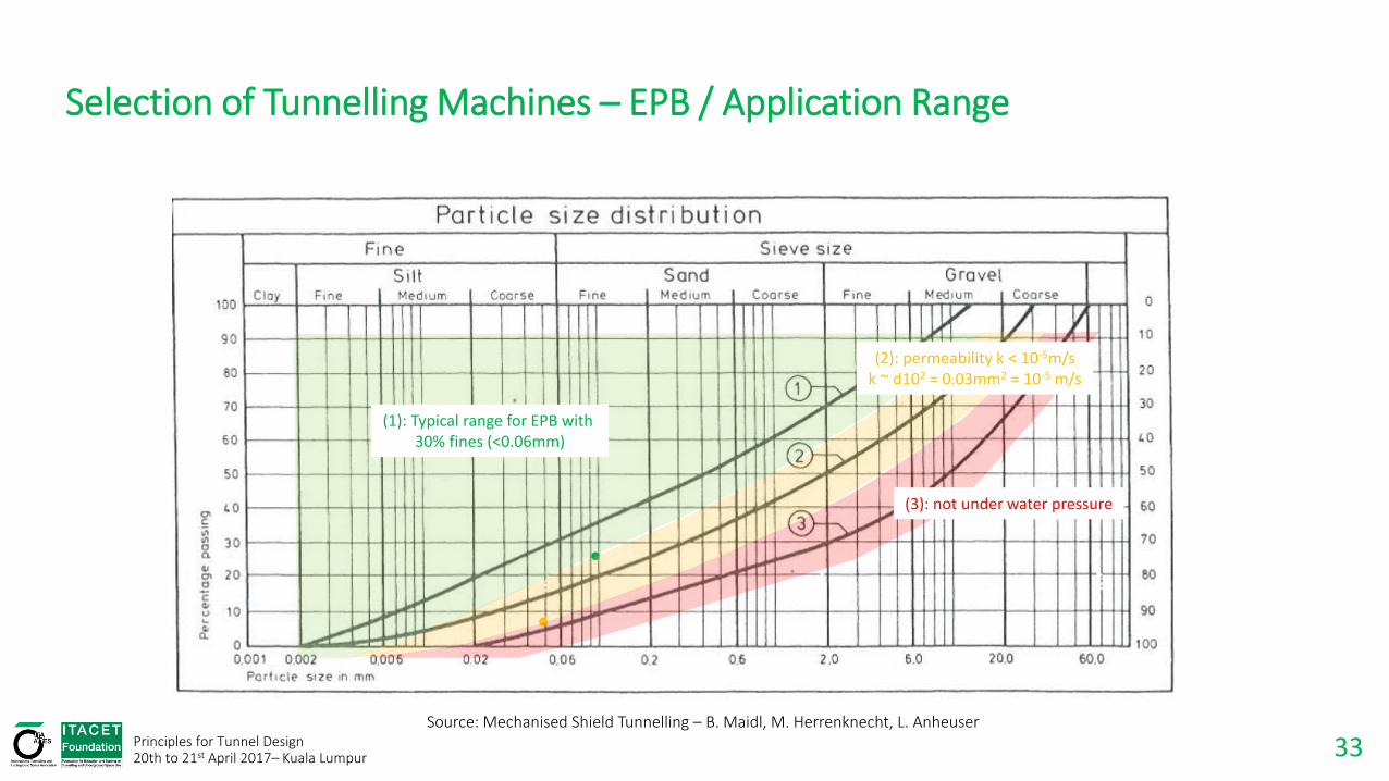
33 Principles for Tunnel Design 20th to 21st April 2017– Kuala Lumpur
Source: Mechanised Shield Tunnelling – B. Maidl, M. Herrenknecht, L. Anheuser
(1): Typical range for EPB with 30% fines (<0.06mm)
(2): permeability k < 10-5m/s k ~ d102 = 0.03mm2 = 10-5 m/s
(3): not under water pressure
Selection of Tunnelling Machines – EPB / Application Range

34 Principles for Tunnel Design 20th to 21st April 2017– Kuala Lumpur
Ideal application on soils with:
High plasticity
Low inner friction
Low permeability
Aim is to maintain conditions with:
Good homogeneous pressure distribution & pressure variation
Low torque for low energy consumption
Low wear
Selection of Tunnelling Machines – Functional Principle EPB

35 Principles for Tunnel Design 20th to 21st April 2017– Kuala Lumpur
Selection of Tunnelling Machines – Functional Principle EPB
1. Cutting Wheel
2. Main Drive
3. Excavation Chamber
4. Screw Conveyor
5. Erector
6. Shield
7. Thrust Cylinders
8. Belt Conveyor
9. Segment Feeder
10.Man lock
11.Backup Gantries / Bridge
12.Tunnel Wall
1
2
3 4
5
6
7
8
9
10 12
11
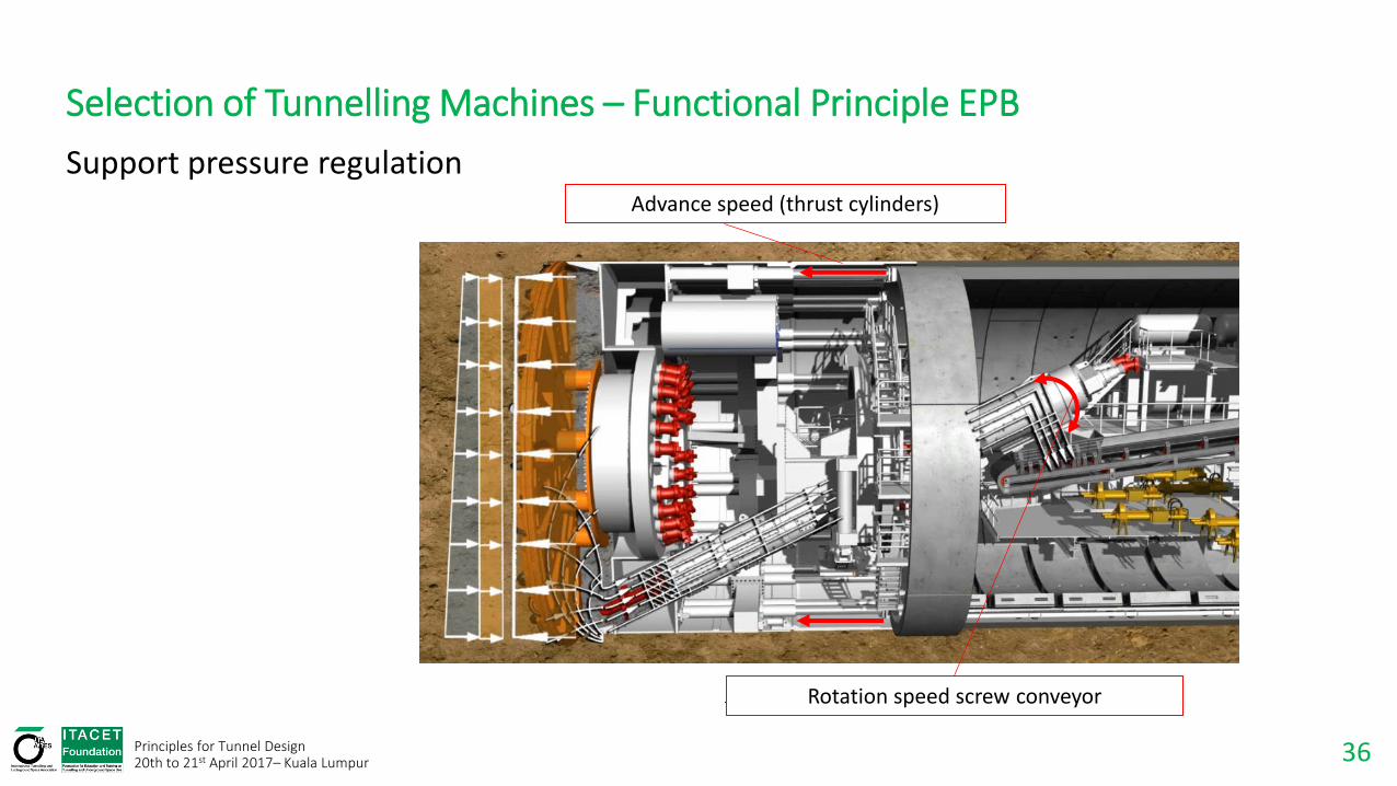
36 Principles for Tunnel Design 20th to 21st April 2017– Kuala Lumpur
Support pressure regulation Advance speed (thrust cylinders)
Rotation speed screw conveyor
Selection of Tunnelling Machines – Functional Principle EPB

37 Principles for Tunnel Design 20th to 21st April 2017– Kuala Lumpur
Support pressure regulation
Closed Mode
To avoid groundwater inflow
For unstable tunnel face
Settlement control
Selection of Tunnelling Machines – Functional Principle EPB

38 Principles for Tunnel Design 20th to 21st April 2017– Kuala Lumpur
Selection of Tunnelling Machines – Mechanised Tunnelling for Soil Conditions
Bulkhead
Air cushion
Cutting wheel
Submerged wall
Air lock
Thrust cylinders
Tailskin
Backfilling or grouting
Erector Slurry circuit
Jaw crusher
Mixshield Functional Principle.
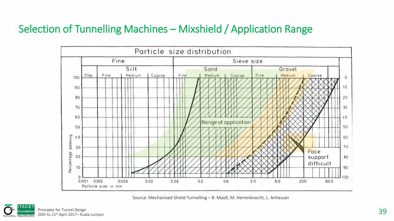
39 Principles for Tunnel Design 20th to 21st April 2017– Kuala Lumpur
Source: Mechanised Shield Tunnelling – B. Maidl, M. Herrenknecht, L. Anheuser
Selection of Tunnelling Machines – Mixshield / Application Range
40 Principles for Tunnel Design 20th to 21st April 2017– Kuala Lumpur
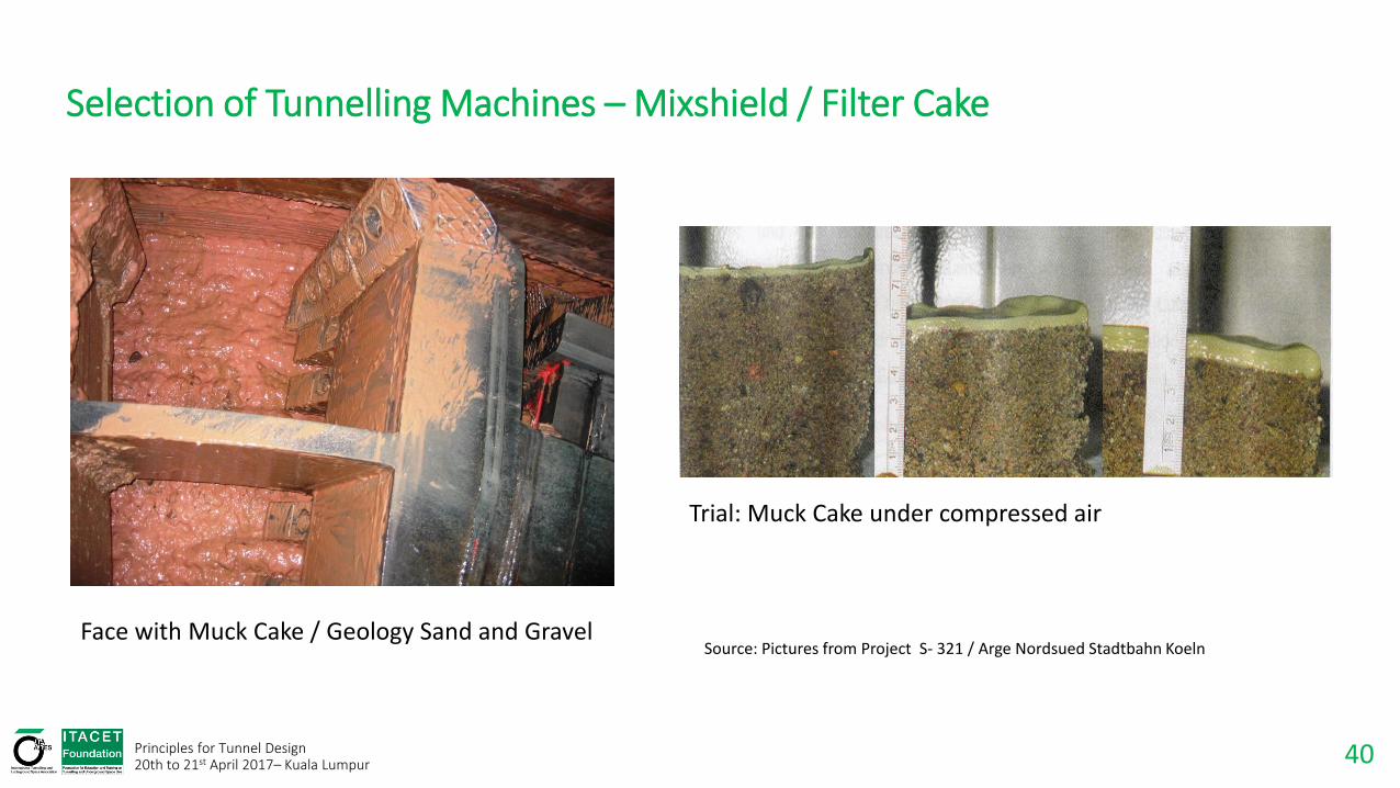
Selection of Tunnelling Machines – Mixshield / Filter Cake
Source: Pictures from Project S- 321 / Arge Nordsued Stadtbahn Koeln Face with Muck Cake / Geology Sand and Gravel
Trial: Muck Cake under compressed air
41 Principles for Tunnel Design 20th to 21st April 2017– Kuala Lumpur
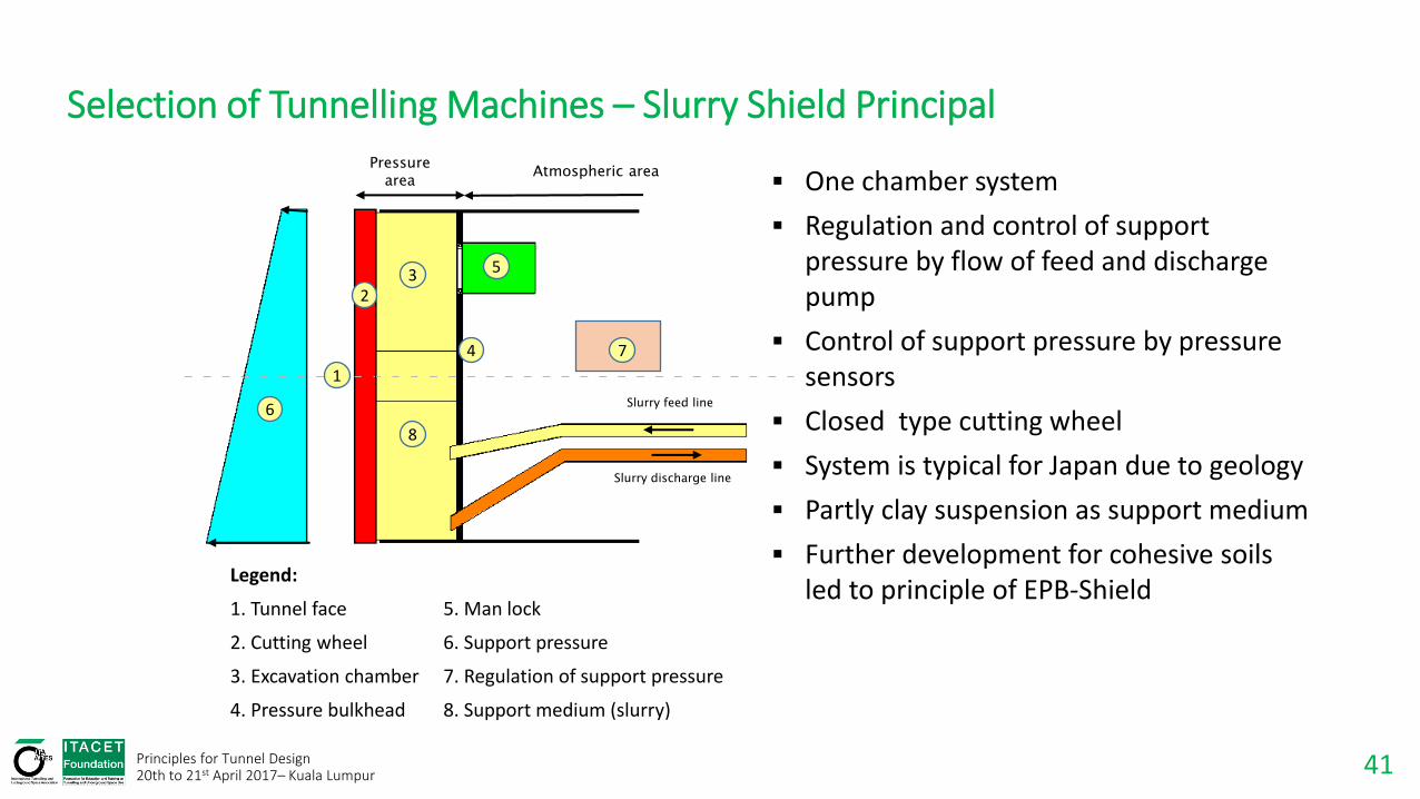
Selection of Tunnelling Machines – Slurry Shield Principal
Legend:
1. Tunnel face 5. Man lock
2. Cutting wheel 6. Support pressure
3. Excavation chamber 7. Regulation of support pressure
4. Pressure bulkhead 8. Support medium (slurry)
Slurry feed line
Slurry discharge line
Atmospheric area Pressure
area
1
2 3
4
5
6
7
8
One chamber system
Regulation and control of support pressure by flow of feed and discharge pump
Control of support pressure by pressure sensors
Closed type cutting wheel
System is typical for Japan due to geology
Partly clay suspension as support medium
Further development for cohesive soils led to principle of EPB-Shield

42 Principles for Tunnel Design 20th to 21st April 2017– Kuala Lumpur
Selection of Tunnelling Machines – Mixshield Principal
Legende:
1. Tunnel face
2. Cutting wheel
3. Excavation chamber
4. Submerged wall
5. Excavation chamber
6. Air bubble
7. Pressure bulkhead
8. Man lock
9. Support pressure
10. Regulation of support pressure
11. Support medium
Pressure area Atmospheric area
Slurry feed line
Slurry discharge line
10
1
2
3
4
5
6
7
8
9
11
43 Principles for Tunnel Design 20th to 21st April 2017– Kuala Lumpur
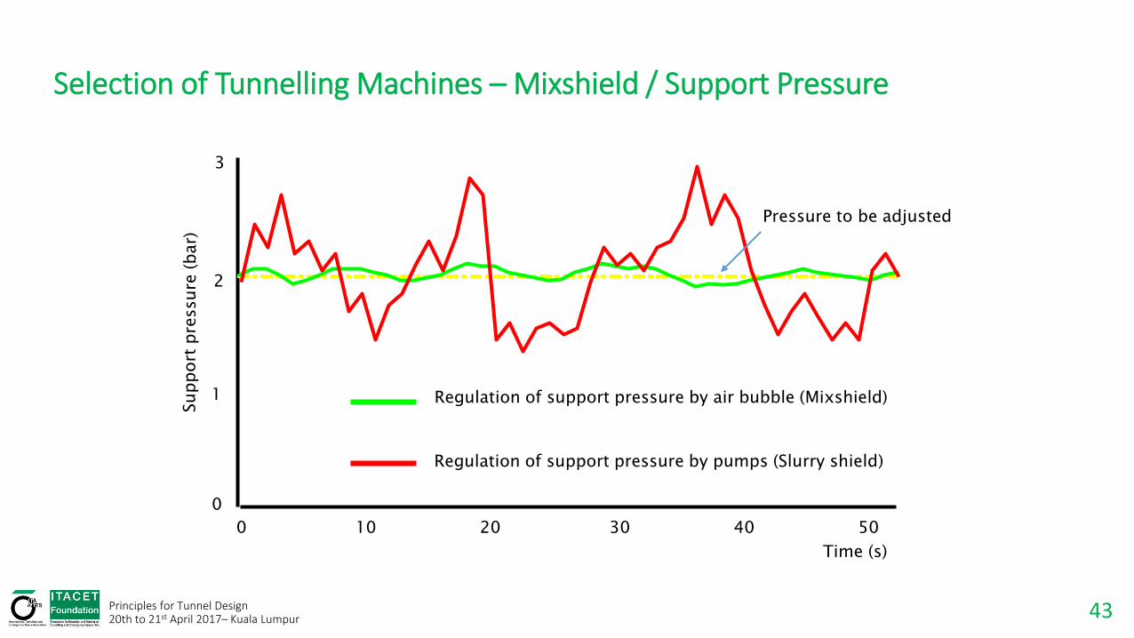
Selection of Tunnelling Machines – Mixshield / Support Pressure
Pressure to be adjusted
0
1
2
3
0 10 20 30 40 50
Time (s)
Regulation of support pressure by air bubble (Mixshield)
Regulation of support pressure by pumps (Slurry shield)

44 Principles for Tunnel Design 20th to 21st April 2017– Kuala Lumpur
Selection of Tunnelling Machines – Mixshield / Slurry Cycle
Slurry = Support of tunnel face and transport medium
Slurry circuit
Separation plant (Bentonite) slurry Mixing plant
Muck discharge Compressor
station
TBM
Compressed air regulation
Slurry feed line
Slurry discharge line
45 Principles for Tunnel Design 20th to 21st April 2017– Kuala Lumpur
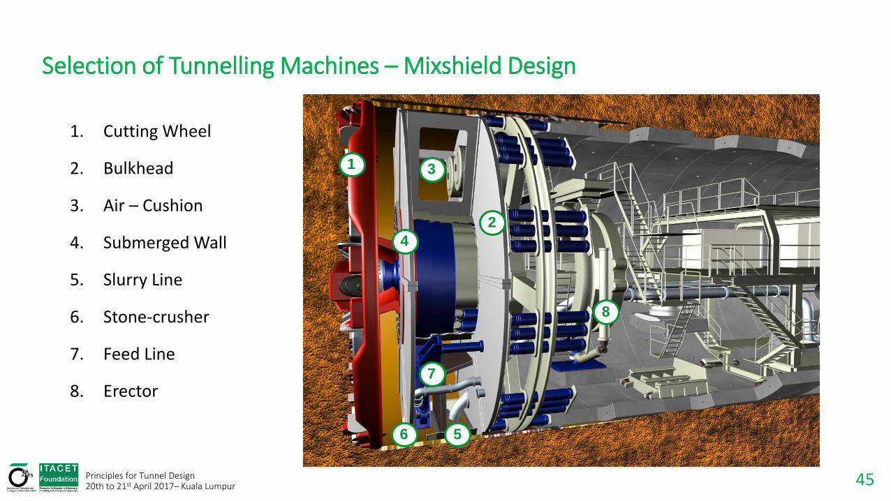
Selection of Tunnelling Machines – Mixshield Design
1. Cutting Wheel
2. Bulkhead
3. Air – Cushion
4. Submerged Wall
5. Slurry Line
6. Stone-crusher
7. Feed Line
8. Erector
1
2
3
4
5 6
7
8
46 Principles for Tunnel Design 20th to 21st April 2017– Kuala Lumpur
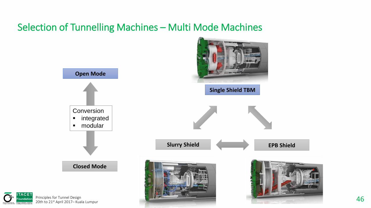
Selection of Tunnelling Machines – Multi Mode Machines
Single Shield TBM
Open Mode
Closed Mode
Slurry Shield EPB Shield
Conversion
integrated
modular

47 Principles for Tunnel Design 20th to 21st April 2017– Kuala Lumpur
Selection of Tunnelling Machines – Convertible Machines
Modular system: Exchange of subassemblies or specific modules → conversion in shaft
Integrated system: Dual systems „on Board“ → conversion in tunnel

48 Principles for Tunnel Design 20th to 21st April 2017– Kuala Lumpur
Selection of Tunnelling Machines – EPB / Open Mode Integrated Concept
Open Mode Screw conveyor in retracted position (reduced capacity) Center belt conveyor and muck ring in working position. Cutter head muck chutes completely installed
Closed Mode - EPB
Screw conveyor in extended position (maximum capacity)
Center belt conveyor and muck ring retracted.
Cutter head muck chutes partly dismantled.
49 Principles for Tunnel Design 20th to 21st April 2017– Kuala Lumpur
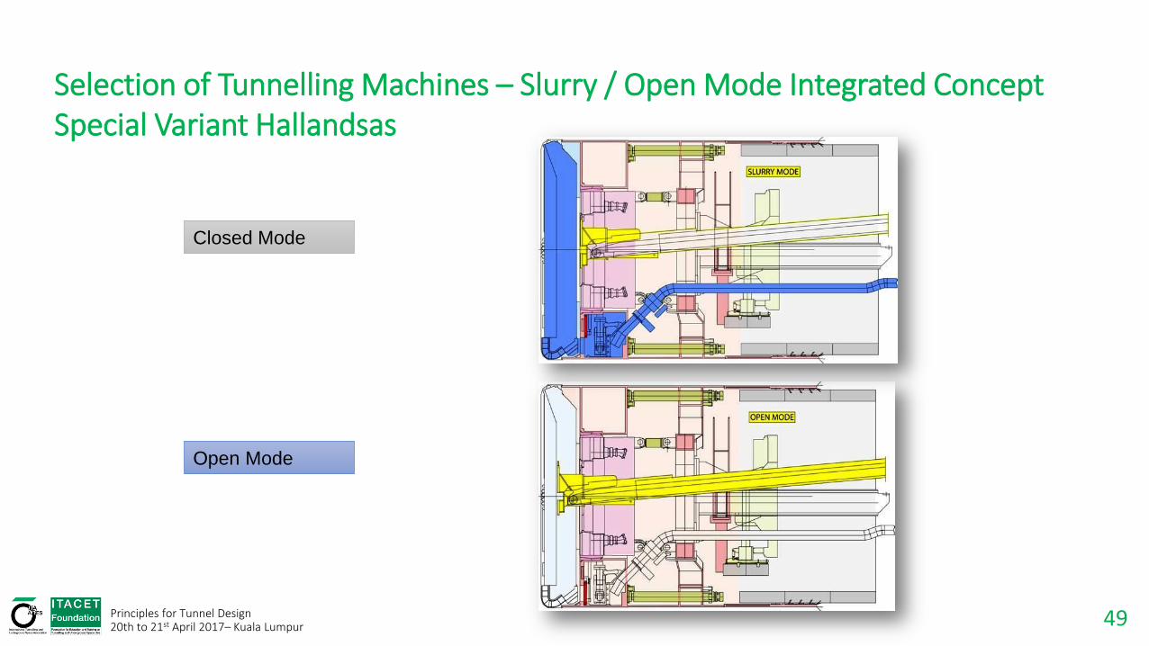
Selection of Tunnelling Machines – Slurry / Open Mode Integrated Concept Special Variant Hallandsas
Open Mode
Closed Mode
50 Principles for Tunnel Design 20th to 21st April 2017– Kuala Lumpur
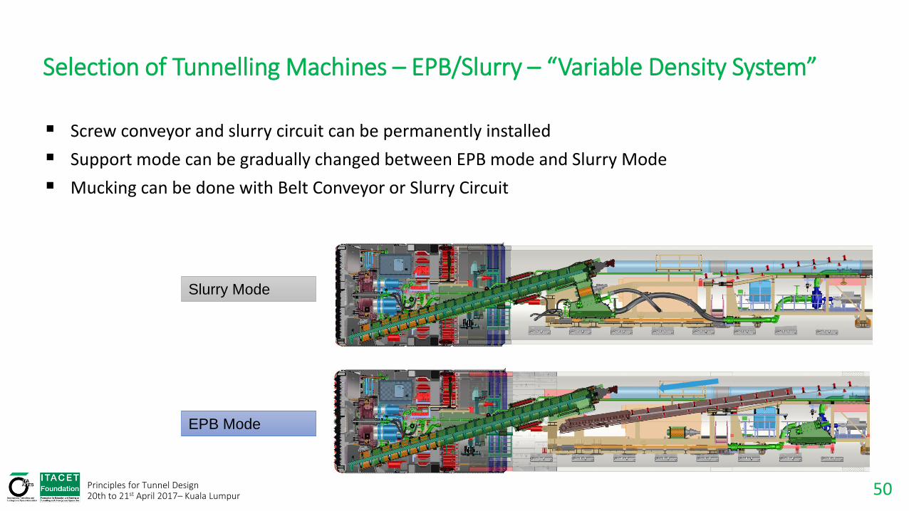
Selection of Tunnelling Machines – EPB/Slurry – “Variable Density System”
Screw conveyor and slurry circuit can be permanently installed
Support mode can be gradually changed between EPB mode and Slurry Mode
Mucking can be done with Belt Conveyor or Slurry Circuit
EPB Mode
Slurry Mode
51 Principles for Tunnel Design 20th to 21st April 2017– Kuala Lumpur
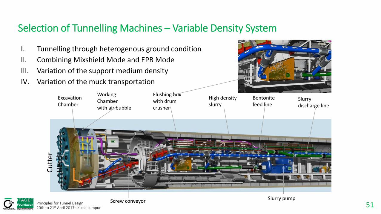
Selection of Tunnelling Machines – Variable Density System
I. Tunnelling through heterogenous ground condition
II. Combining Mixshield Mode and EPB Mode
III. Variation of the support medium density
IV. Variation of the muck transportation
Working Chamber with air bubble
Cu
tter
H
ead
Screw conveyor
Flushing box with drum crusher
High density slurry
Slurry pump
Bentonite feed line
Slurry discharge line
Excavation Chamber
52 Principles for Tunnel Design 20th to 21st April 2017– Kuala Lumpur
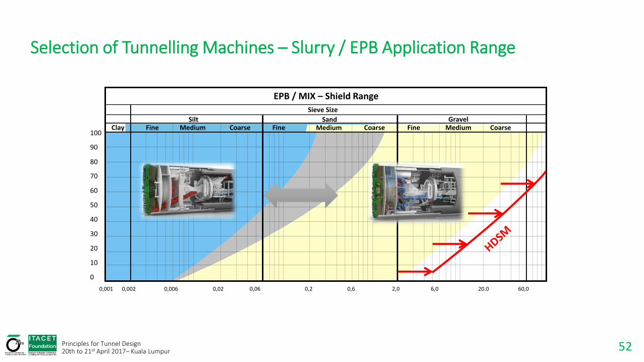
Selection of Tunnelling Machines – Slurry / EPB Application Range
60,0 20.0 6,0 2,0 0,6 0,2 0,06 0,02 0,006 0,002 0,001
100
90
40
30
20
10
0
80
70
60
50
Sieve Size
Fine Clay Silt Sand Gravel
Medium Medium Coarse Fine Coarse Fine Medium Coarse
EPB / MIX – Shield Range
53 Principles for Tunnel Design 20th to 21st April 2017– Kuala Lumpur
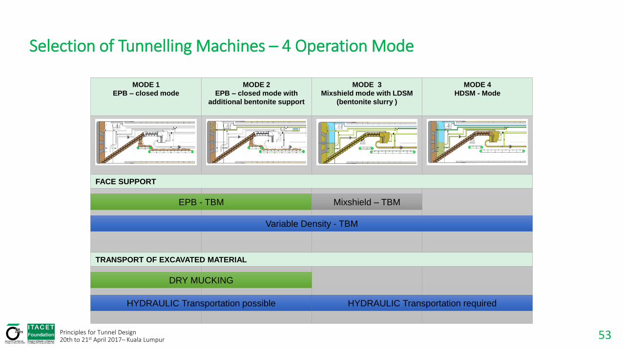
Selection of Tunnelling Machines – 4 Operation Mode
MODE 1
EPB – closed mode
MODE 2
EPB – closed mode with
additional bentonite support
MODE 3
Mixshield mode with LDSM
(bentonite slurry )
MODE 4
HDSM - Mode
FACE SUPPORT
TRANSPORT OF EXCAVATED MATERIAL
EPB - TBM Mixshield – TBM
Variable Density - TBM
HYDRAULIC Transportation possible
DRY MUCKING
HYDRAULIC Transportation required

54 Principles for Tunnel Design 20th to 21st April 2017– Kuala Lumpur
Selection of Tunnelling Machines – Mixed Face Conditions in the „KL-limestone.“
GW
Soft ground
Surface
Cavity
Sinkhole ! Overhang Collapsed
cavity
Hard rock

55 Principles for Tunnel Design 20th to 21st April 2017– Kuala Lumpur
Selection of Tunnelling Machines – Variation Of Support Medium Density.
pSL – γld x h
pSL – γhd x h
LDSM - low density
support medium HDSM - high density
support medium
GW
Ground level
h
(γhd > γld )
FS_ HDSM FS _LDSM =
earth pressure
water pressure
Slurry pressure pSL
Pressure gradient with LDSM (γld )
Pressure gradient with HDSM (γhd )

56 Principles for Tunnel Design 20th to 21st April 2017– Kuala Lumpur
Selection of Tunnelling Machines – Important Technical Trends
Larger TBM Diameters
Multi Mode Machine Development
2,5
3,5 3,54,0
5,5
7,5
11,0
14,0
11,0
0,0
2,5
5,0
7,5
10,0
12,5
15,0
17,5
Face
Pre
ssu
re [
bar
]
HERA HAMBURGMixshield, Ø 6.0m
SYDNEYMixshield, Ø 10.4m
MÜLHEIMMixshield, Ø 6.9m
GRAUHOLZMixshield, Ø 11.6m
HAMBURG4TH ELBTUNNELMixshield, Ø 14.2m
WESTERSCHELDEMixshield, Ø 11.4m
HALLANDSASMixshield, Ø 10.53m
ISTANBULMixshield, Ø 13.71m
DIVERS
ENGAGED
LAKE MEADMixshield, Ø 7.18m
1985 HERA 5.95m
1996 Sydney 10.70m
1997 Hamburg 14.20m
Concept St. Petersburg
19.25m
2006 Shanghai 15.43m
2013 Hong Kong
17.6m
Multi Purpose Tunnels
Higher Pressures

57 Principles for Tunnel Design 20th to 21st April 2017– Kuala Lumpur
Literature / Links
B. Maidl, M. Herrenknecht, U. Maidl, G. Wehrmeyer: Mechanised Shield Tunnelling; 2. Edition, 2011
B. Maidl, L. Schmid, W. Rotz, M. Herrenknecht: Hardrock Tunnel Boring Machines, 2008
Deutscher Ausschuss fuer unterirdisches Bauen (DAUB): Recommendations for selecting and evaluating tunnel boring, 1997
German-Czech Scientific Foundation: Mechanised Tunnelling and Segmental Lining, 2009
Schmid L.: Einsatz großer Tunnelbohrmaschinen verschiedener Bauart in der Schweiz – Leistungen und Wirtschaftlichkeit . In: Forschung + Praxis 29., 1980
D. Kolymbas: Tunnelling and Tunnel Mechanics; 2. Edition, 2010
http://www.daub-ita.de/en/start/
https://www.ita-aites.org/en/
https://www.herrenknecht.com/en/home.html

58
Disclaimer a) The speakers are presenting their own personal views and are not expressing the view of the Foundation. b) Papers and documents displayed or handed out during the Event are copyrighted. The participants must observe and comply with all applicable law regulations concerning the copyright.
Principles for Tunnel Design
20th to 21st April 2017– Kuala Lumpur