principle of energy conservation
TRANSCRIPT

Principle of Energy Conservation
Principle of Energy
Conservation

Principle of Energy Conservation
4.1 Energy, Work and Heat
5.1 1st Law for Control Mass
5.2 Specific Heats for Ideal Gas
5.3 1st Law for Control Volume
5.4 Steady-State, Steady-Flow Process
5.5 Uniform-State, Uniform-Flow Process

Principle of Energy Conservation
Energy, Work and Heat
Two major concepts of thermodynamics are energy
and entropy. They are both abstract concepts in
classical thermodynamics, which are derived from
the 1st and 2nd law of thermodynamics.
Energy, Work and Heat
4.1 Energy, Work and Heat

Principle of Energy Conservation
(Energy)
SystemWork
EnergyFlow
EnergyFlow
Heat
Surrounding
Energy, Work and Heat

Principle of Energy Conservation
Energy
Macroscopic view1st Law : Energy can be transferred in two different forms,heat and work. Energy is an abstract concept givenas a thermodynamic property, defined in terms ofthe 1st law of thermodynamics.
Microscopic viewEnergy can be stored in many different forms;intermolecular potential energy, molecular kineticenergy and intermolecular energy including rotationaland vibrational energy.
dE Q W
Energy, Work and Heat

Principle of Energy Conservation
Work and Heat
There are only two forms of energy transfer, work and heat.
Work : a form of energy transfer due to an externally applied force and resulting displacement of the system
F can be any generalized force and x is the corresponding generalized displacement.
Conventionally work is defined as positive if energy is transferred from the system to the surrounding.
W Fdx
Energy, Work and Heat
Principle of Energy Conservation
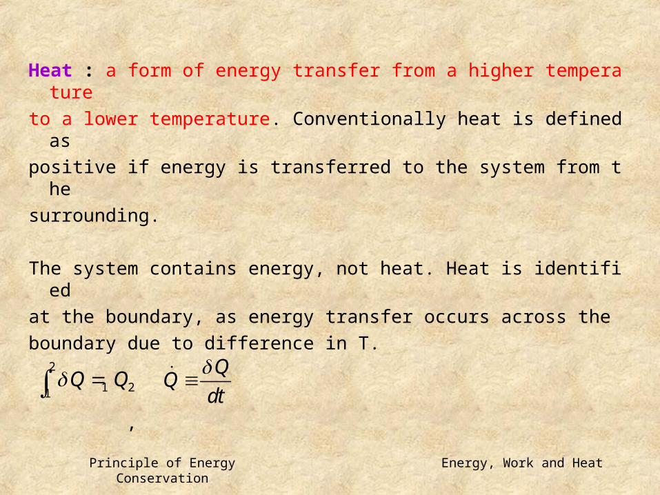
Heat : a form of energy transfer from a higher temperature to a lower temperature. Conventionally heat is defined aspositive if energy is transferred to the system from thesurrounding.
The system contains energy, not heat. Heat is identified at the boundary, as energy transfer occurs across theboundary due to difference in T.
,2
1 21Q Q
dt
Energy, Work and Heat

Principle of Energy Conservation
Units for work are same as those for energy.1 J = 1 Nm
Power:
1 W = 1 J/s1 hp = 550 lbf ft/s
Specific work: work per unit mass of the system
WW
dt
Ww
m
Energy, Work and Heat

Principle of Energy Conservation
Units of heat are same as those for work.1 btu = 1.055056 kJ1 cal = 4.1868 J
Specific heat transfer; heat transfer per unit mass ofthe system
Adiabatic process; Q=0
m
Energy, Work and Heat

Principle of Energy Conservation
Example of work crossing the boundary of a system
Energy, Work and Heat

Principle of Energy Conservation
Example of work crossing the boundary of a system
because of a flow of an electric current across the system boundary
Energy, Work and Heat

Principle of Energy Conservation
System > TsurrTsys
Surrounding
Heat
Energy, Work and Heat

Principle of Energy Conservation
Schematic arrangement showing work done on a surface film
Energy, Work and Heat

Principle of Energy Conservation
Schematic arrangement fir magnetic cooling
Energy, Work and Heat

Principle of Energy Conservation
Work done at the moving boundary in a quasi-
equilibrium process
Quasi-equilibrium process : internally reversible process.
Infinitesimal change to maintain equilibrium throughoutthe process.
Non-equilibrium process : the intermediate states cannot be defined. The force exerted by the pressure ofgas does not equal the external force.
W PdV 2 2
1 2 1 1W W PdV
extW P dV
Energy, Work and Heat

Principle of Energy Conservation
Use of pressure-volume diagram to show work done
at the moving boundary of a system in a quasi -equilibrium process
Energy, Work and Heat
Principle of Energy Conservation
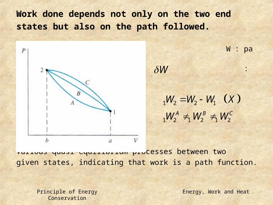
Work done depends not only on the two end states but also on the path followed. W : path function : inexact differential
Various quasi-equilibrium processes between twogiven states, indicating that work is a path function.
1 2 2 1
1 2 1 2 1 2A B C
W W W X
W W W
W
Energy, Work and Heat

Principle of Energy Conservation
2 1 2 1
1 2 1 2
2 1 2 1
1 2 1 2
2 2 2 2
1 1 1 1
2 2
1 1
A B A B
C B C B
A C A C
A C
Q W
Q Q W W
Q Q W W
Q Q W W
Q W Q W
Energy, Work and Heat

Principle of Energy Conservation
Q W
dE Q W
1 2 2 1 1 2
2
2
Q E E W
dE dU mVdV mgdZ
d mVQ dU d mgZ W
: point function
Energy, Work and Heat

Principle of Energy Conservation
Point Functionsthermodynamic properties
e.g. V, U, H, ρ
The change in volume depends only on the two end states.
dV : exact differential
2
2 11dV V V
Energy, Work and Heat
Principle of Energy Conservation
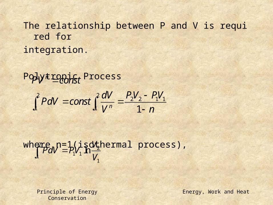
The relationship between P and V is required for integration.
Polytropic Process
where n=1(isothermal process),
2 22 2 1 1
1 1 1
n
n
PV const
dV PV PVPdV const
V n
22
1 111
lnV
PdV PVV
Energy, Work and Heat

Principle of Energy Conservation
Other Modes of Work
각 항 설명
There is only one mode of heat, while there can be
many different modes of work.
0W PdV dL dA Hd V dZ M E
Energy, Work and Heat

Principle of Energy Conservation
Non-equilibrium Process; No Work is involved.
Example of a process involving a change of volume for which work is zero
Energy, Work and Heat

Principle of Energy Conservation
Heat and Work
(1) Both are transient phenomena.They cross the boundary as the system undergoes a change in its state.
(2) Both are boundary phenomena.They represent energy crossing the boundary of the system.
(3) Both are path functions and inexact differentials.
Thermodynamic properties are state or point functions,
which do not depend on the previous path or history. Energy, Work and Heat

Principle of Energy Conservation
Identification of works involved is an importantpart of many thermodynamic problems.
Example showing how selection of the system determines whether workis involved in a process
Energy, Work and Heat

Principle of Energy Conservation
An example showing the difference between heat and work
Energy, Work and Heat

Principle of Energy Conservation
Example 4.1Consider as a system the gas in the cylinder. The cylinderis fitted with a piston on which a number of small weightsare placed. The initial pressure is 200kPa, and the initialvolume of the gas is 0.4m3.
1. Let a Bunsen burner be placed under the cylinder, and let the volume of the gas increase to 0.1m3
while the pressure remains constant. Calculate the work done by the system during this process.
2 2
1 2 2 11 112.0W PdV P dV P V V kJ
Energy, Work and Heat

Principle of Energy Conservation
2. Consider the same system and initial conditions,
but at same time the Bunsen burner is under the
cylinder and the piston is rising, let weights be removed from the piston at such a rate that,
during the process, the temperature of the gas
remains constant.
n=1
22
1 2 1 111
ln 7.33V
W PdV PV kJV
Energy, Work and Heat

Principle of Energy Conservation
3. Consider the same system, but during the heat
transfer let the weights be removed at such a rate
that the expression describes the
relation between pressure and volume during the
process. Again the final volume is 0.1m3. Calculate the work.
1.3
2
0.04200 60.77
0.10P kPa
1.3PV const
22 2 1 1
1 2 16.41
1 1.3
PV PVW PdV kJ
Energy, Work and Heat

Principle of Energy Conservation
4. Consider the system and initial state in the first three examples, but let the piston be held by a
pin so that the volume remains constant. In
addition, let heat be transferred from the system until
the pressure drops to 100kPa. Calculate the work.
The work is zero, because there is no change in
volume.
Energy, Work and Heat
Principle of Energy Conservation
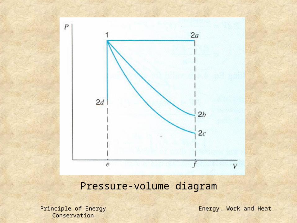
Pressure-volume diagram
Energy, Work and Heat

Principle of Energy Conservation
Example 4.2Consider a slightly different piston cylinder arrangement as shown in Fig.4.8. In this example the piston is loadedwith a mass, mp, the outside atmosphere P0, a linear
spring and a single point force F1. The piston is restricted
in its motion by lower and upper stops trapping the gaswith a pressure P. A force balance on the piston in the direction of motion yields
with a zero acceleration in a quasi-equilibrium process. The forces, when the piston between the stops, are
0pm a F F
Energy, Work and Heat

Principle of Energy Conservation
with the linear spring constant, ks. The piston position
for a relaxed spring is x0, which depends on how the
spring is installed. The force balance then gives the gas pressure by division with the area, A as
To illustrate the process in a P-V diagram, the distancex is converted to volume by multiplication with A:
0 0 1p sF m g P A k x x F F PA
0 1 0 /p sP P m g F k x x A
10 0 1 22
p sm g kF
P P V V C C VA A A
Energy, Work and Heat

Principle of Energy Conservation
This relation gives the pressure as a linear function ofthe volume, with the line having a slope of C2=ks/A2.
With the stops installed, the minimum and maximum volumes limit the possible states of the system to the Combination of P and V as shown in Fig.4.9. Regardless of what substance is inside, any process must proceedalong the lines in the P-V diagram. The work term in a quasi-equilibrium process then follows as
2
1 2 1( )W PdV AREA under process curve
' '1 2 1 2 2 1
1
2W P P V V
Energy, Work and Heat

Principle of Energy Conservation
with and , subject to the constraintthat
These limits show that only the part of the process that follows the sloped line, when the piston moves,contributes to the work. Any part of the process with a pressure smaller than Pmin or larger than Pmax does
not involve work as the piston is held in fixed piston by one of the stops. The maximum work then arises,when the piston travels the total distance between the two stops.
'1 1P P '
2 2P P
' 'min 1 2 max,P P P P
Energy, Work and Heat

Principle of Energy Conservation
The process curve showing possible P-V combination
Energy, Work and Heat

Principle of Energy Conservation
The 1st Law of Thermodynamics(Conservation of Energy)
Example of a control mass undergoing a cycle
Q W
5.1 1st Law for Control Mass
1st Law for Control Mass

Principle of Energy Conservation
Control Mass Undergoing a Process
E : all energy of the system
Energy Conservation The net change of the energy is always equal to the net transfer of energy across the boundary as heatand work.
dE
dE Q W
dEQ W
dt
(work)
System
(heat)Q
W
dE
1st Law for Control Mass

Principle of Energy Conservation
Internal Energy E = U + KE + PEU : internal energy
E represents all the energy of the system in the givenstate.
Kinetic and potential energy(KE and PE) depend on the coordinate frame that we choose to select. They can be specified by the macroscopic properties ofmass, velocity and elevation.
Internal energy(U) is a thermodynamic property, whichmay be uniquely given from the thermodynamic state of the system.
1st Law for Control Mass

Principle of Energy Conservation
No information about the absolute magnitude of the
internal energy.
U : extensive propertyu : intensive property
2 22 1
1 2 2 1 2 1 1 22
m V VQ U U mg Z Z W
2
2
d mVQ dU d mgZ W
Uu
m
f fgu u xu
1st Law for Control Mass

Principle of Energy Conservation
Example 5.2Consider a stone having a mass of 10kg and a bucket containing 100kg of liquid water. Initially the stone is10.2m above the water, and the stone and the waterare at the same temperature, state 1. The stone thenfalls into the water.Determine △U, △KE, △PE, Q, and W for the followingchanges of state, assuming standard gravitationalacceleration of 9.80665m/s2
a. The stone is about to enter the water, state 2. b. The stone has just come to rest in the bucket, state 3.
1st Law for Control Mass

Principle of Energy Conservation
c. Heat has been transferred to the surroundings in such an amount that the stone and water are at the temperature, , state 4.
1. The stone has fallen from to , and we assume no heat transfer as it falls.
; ;
For the process from state 1 to state 2, and
1T
Q U KE PE W
2Z 1Z
0U 1 2 0Q 1 2 0W
2 1
0
1000 1
KE PE
KE PE mg Z Z J kJ
1KE kJ 1PE kJ
1st Law for Control Mass

Principle of Energy Conservation
2. For the process from state 2 to state 3 with zero
kinetic energy ; ;
3. In final state, ; ; ;
0PE 2 3 0Q 2 3 0W
3 4 0W 0PE 0KE 1U kJ
0
1
U KE
U KE kJ
3 4 1Q U kJ
1st Law for Control Mass

Principle of Energy Conservation
Example 5.3A vessel having a volume of 5m3, contains 0.05m3 ofsaturated liquid water and 4.95m3 of saturated watervapor at 0.1MPa. Heat is transferred until the vessel isfilled with saturated vapor. Determine the heat transferfor this process.
Control mass : All the water inside the vessel. Initial state : Pressure, volume of liquid, volume of vapor; State 1 is fixed. Final state : Somewhere along the saturated- vapor curve; the water was heated, so P2>P1.
1st Law for Control Mass

Principle of Energy Conservation
process : constant volume and mass, therefore, constant specific volume.
1 2 2 1Q U U
2 22 1
1 2 2 1 2 1 1 22
V VQ U U m mg Z Z W
1
1
0.0547.94
0.001043
4.952.92
1.6940
liqliq
f
vapvap
g
Vm kg
v
Vm kg
v
1 1 1 1 1 27326liq liq vap vapU m u m u kJ
1st Law for Control Mass
Principle of Energy Conservation
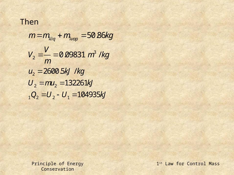
Then
1 1 50.86liq vapm m m kg
32 0.09831 /
VV m kg
m
2
2 2
1 2 2 1
2600.5 /
132261
104935
u kJ kg
U mu kJ
Q U U kJ
1st Law for Control Mass

Principle of Energy Conservation
Problem Analysis
(1) Define the system. Control mass or control volume?(2) Find out the initial and final states.(3) Description of the process.(4) Diagram of the process helps.(5) How to obtain thermodynamic properties.(6) Analysis of the problem. 1st or 2nd laws? Relevant work modes? (7) Solution technique. Numerical solution? Trial-and-error?
1st Law for Control Mass

Principle of Energy Conservation
Enthalpy H = U + PVh = u + Pv (h=H/m)
Enthalpy is also a thermodynamic property, which may be defined as either an extensive or an intensiveproperty. (H or h)
In a constant pressure process;
1 2 2 1 1 2Q U U W
1 2 2 1W P V V
1st Law for Control Mass

Principle of Energy Conservation
therefore
The combination, U+PV, appears often in control volume analysis of the 1st law of thermodynamics.
1 2 2 2 2 1 1 1 2 1Q U PV U PV H H
1st Law for Control Mass

Principle of Energy Conservation
Example 5.4A cylinder fitted with a piston has a volume of 0.1m3 and contains 0.5kg of steam at 0.4MPa. Heat istransferred to the steam until the temperature is 300C, while the pressure remains constant.Determine the heat transfer and the work for this process.Control mass: Water inside cylinder.Initial state: P1, V1, m; therefore v1 is known, state 1 is
fixed(at P1, v1, check steam table - two-phase region).
Final state: P2, T2; therefore state 2 is fixed(superheated).
Process: Constant pressure.Model: Steam tables.
1st Law for Control Mass

Principle of Energy Conservation 1st Law for Control Mass

Principle of Energy Conservation
No change in kinetic energy, no change in potential energy. Work is done by movement at the
boundary.Assume the process to be quasi-equilibrium. Since
thepressure is constant,
Therefore , the first law is
2 2
1 2 2 1 2 2 1 11 1W PdV P dV P V V m P v Pv
1 2 2 1 1 2 2 1 2 2 1 1 2 1Q m u u W m u u m P v Pv m h h
1st Law for Control Mass

Principle of Energy Conservation
11 1
1
1 1
2
1 2
1 2 2 1
2 1 1 2 1 2
0.2 0.001084 0.4614
0.4311
1524.7
3066.8
0.5 3066.8 1524.7 771.1
91.0
680.1
f fg
Vv x
mx
h h x h
h
Q kJ
W mP v v kJ
U U Q W kJ
1st Law for Control Mass

Principle of Energy Conservation
Specific Heats
Specific heat at constant volume :
Specific heat at constant pressure :
The specific heats are thermodynamic properties.
(A function in terms of thermodynamic properties is
itself a thermodynamic property.)
For solid and liquid,
vv
uC
T
pp
hC
T
2 1 2 1 2 1
p vdh du CdT C C C
h h u u C T T
Specific Heats for Ideal Gas
5.2 Specific Heats for Ideal Gas

Principle of Energy Conservation
Internal Energy, Enthalpy and Specific Heats of Ideal GasFor ideal gas the internal energy and enthalpy are thefunctions of temperature only.
Ideal gas specific heats are also called as zero-pressure specific heats, , .
from 0 0p vC C R
0vC T 0pC T
v
p
duC f T
dTdh
C f TdT
u u T
h h T
h u RT
Specific Heats for Ideal Gas

Principle of Energy Conservation
The energy in a molecule may be stored in severalforms. Translational and rotational energies increase linearly with temperature. Vibrational energy is temperature dependent.
monoatomic : Ar, Ne, He (f=3)diatomic : Air, O2, H2 (f=6)
polyatomic : CO2, H2O (f=9)
Specific Heats for Ideal Gas

Principle of Energy Conservation
Specific Heats
Constant-pressure specific heats for a number of gases at zero pressure
Specific Heats for Ideal Gas

Principle of Energy Conservation
Enthalpy from Specific Heats of Ideal Gas
- constant less accurate except for monatomic gases
- as an analytical function of T close empirical approximation
- Gas Table most accurate
0pC
0pC
Specific Heats for Ideal Gas

Principle of Energy Conservation
Example 5.6Calculate the change of enthalpy as 1kg of oxygen
is heated from 300 to 1500K. Assume ideal-gas
behavior.
Our most accurate answer for the ideal-gas enthalpy
change for oxygen between 300 and 1500K would be
from the ideal-gas tables, Table A.13.
1500 300
2 1 1267.0 /h h
h h kJ kgM
Specific Heats for Ideal Gas
Principle of Energy Conservation
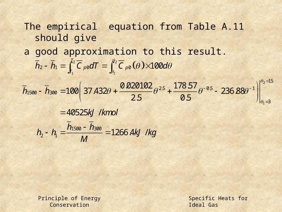
The empirical equation from Table A.11 should give
a good approximation to this result.
2 2
1 1
2
1
2 1 0 0
15
2.5 0.5 11500 300
3
1500 300
2 1
100
0.020102 178.57100 37.432 236.88
2.5 0.5
40525 /
1266.4 /
T
p pT
h h C dT C d
h h
kJ kmol
h hh h kJ kg
M
Specific Heats for Ideal Gas

Principle of Energy Conservation
If we assume constant specific heat, we must be concerned about what value we are going to use. Ifwe use the value at 300K from Table A.10,
On the other hand, suppose we assume that the specific
heat is constant at its value at 900K, the averagetemperature. Substituting 900K into the equation forspecific heat from Table A.11,
2 1 0 2 1 1105.9 /ph h C T T kJ kg
0
2 1
1.0714 /
1285.7 /
pC kJ kgK
h h kJ kg
Specific Heats for Ideal Gas

Principle of Energy Conservation
Example 5.7A cylinder fitted with a piston has an initial volume
of 0.1m3 and contains nitrogen at 150kPa, 25C. The piston is moved, compressing the nitrogen until the pressure is 1MPa and the temperature is 150C.
Duringthis compression process heat is transferred from
the nitrogen, and the work done on the nitrogen is
20kJ. Determine the amount of this heat transfer.
Specific Heats for Ideal Gas

Principle of Energy Conservation
First law: 1 2 2 1 1 2Q m u u W
1 2 0 2 1 1 2
150 0.10.1695
0.2968 298.154.2v
PVm kg
RTQ mC T T W kJ
Control mass: Nitrogen.
Initial state: P1, T1, V1; state 1 fixed.
Final state: P2, T2; state 2 fixed.
Process: work input known.
Model: Ideal gas, constant specific heat at 300K,
Table A.10
Specific Heats for Ideal Gas

Principle of Energy Conservation
Example 5.8During the charging of a storage battery, the
current is 20A and the voltage is 12.8V. The rate of heat transfer from the battery is 10W. At what rate is
the internal energy increasing?
256
246 /
dUQ W
dt
W Ei W
dUQ W J s
dt
Specific Heats for Ideal Gas

Principle of Energy Conservation
Control Volume Formulation : Mass
5.3 1st Law for Control Volume
1st Law for Control Volume

Principle of Energy Conservation
Control Volume Formulation : Energy
1st Law for Control Volume

Principle of Energy Conservation
Control Volume Formulation (수식 )
1st Law for Control Volume

Principle of Energy Conservation
Steady State, Steady Flow(SSSF) Process
1. CV at rest.2. SS everywhere in the CV.3. SS for flows across the CS. SS for heat and work.
where ,
i em m m
2 2
2 2i e
i i e e
V Vq h gZ h gZ w
. .c vQq
m
. .c vW
wm
Steady-State, Steady-Flow Process
5.4 Steady-State, Steady-Flow Process

Principle of Energy Conservation
Example 5.10The mass rate of flow into a steam turbine is
1.5kg/s,and the heat transfer from the turbine is 8.5kW.
The following data are known for the steam entering
and leaving the turbine.
Steady-State, Steady-Flow Process

Principle of Energy Conservation
Determine the power output of the turbine.Control volume: Turbine.Inlet state: Fixed.Exit state: Fixed.Process: SSSF.Model: Steam tables.
First law
with . . 8.5c vQ kW
2 2
. . . .2 2i e
c v i i e e c v
V VQ m h gZ m h gZ W
Steady-State, Steady-Flow Process

Principle of Energy Conservation
hi=3137.0kJ/kg
he=2675.5kJ/kg
2
1.25 /2
0.059 /
i
i
VkJ kg
gZ kJ kg
2
20.0 /2
0.029 /
e
e
VkJ kg
gZ kJ kg
. . 655.7
437.11 /
5.667 /
c vW kW
w kJ kg
q kJ kg
Steady-State, Steady-Flow Process

Principle of Energy Conservation
Example 5.11Steam at 0.6MPa, 200C enters an insulated nozzle with a velocity of 50m/s. It leaves at a pressure of 0.15MPa and a velocity of 600m/s. Determine the final temperature if the steam is superheated in
the final state, and the quality if it is saturated.
Control volume: Nozzle.Inlet state: Fixed.Exit state: Pe known.
Process: SSSF.Model: Steam tables.
Steady-State, Steady-Flow Process

Principle of Energy Conservation
. .
. .
2 2
0
0
2 2
2671.4 /
2671.4 467.1 2226.5
0.99
c v
c v
i e
i ei e
e
f fg
e
e
Q
W
PE PE
V Vh h
h kJ kg
h h xh
x
x
Steady-State, Steady-Flow Process

Principle of Energy Conservation
Example 5.12In a refrigeration system, in which R-134a is the refrigerant, the R-134a enters the compressor at 200kPa, -10C and leaves at 1.0MPa, 70C. The mass rate of flow is 0.015kg/s, and the power input to the compressoris 1kW.On leaving the compressor the refrigerant enter a water-cooled condenser at 1.0MPa, 60C and leaves as a liquidat 0.95MPa, 35C. Water enters the condenser at 10C and leaves at 20C. Determine:
1. The heat transfer rate from the compressor.2. The rate at which cooling water flows through the condenser.
Steady-State, Steady-Flow Process

Principle of Energy Conservation
First control volume: Compressor.Inlet state: Pi, Ti; state fixed.
Exit state: Pe, Te; state fixed.
Process: SSSF.Model: R-134a tables.
. .
66.67 /
392.34 /
452.35 /
6.66 /
0.10
i e
i
e
c v
q h h w
w kJ kg
h kJ kg
h kJ kg
q kJ kg
Q kW
Steady-State, Steady-Flow Process

Principle of Energy Conservation
Second control volume: Condenser.Inlet states: R-134a-fixed; water-fixed.Exit states: R-134a-fixed; water-fixed.Process: SSSF.Model: R-134a tables; steam tables.
441.89 / 42.00 /
249.10 / 83.95 /
i i e e
r i w i r e w er w r w
i ir w
e er w
m h m h
m h m h m h m h
h kJ kg h kJ kg
h kJ kg h kJ kg
Steady-State, Steady-Flow Process

Principle of Energy Conservation
. .
. .
0.0689 /
2.892
0.0689 /
w
c v r e i r
c v w e i w
w
m kg s
Q m h h kW
Q m h h
m kg s
Steady-State, Steady-Flow Process

Principle of Energy Conservation
Example 5.13Consider the simple steam power plant. The
followingdata are for such a power plant.
Steady-State, Steady-Flow Process

Principle of Energy Conservation
Simple steam power plant
Steady-State, Steady-Flow Process

Principle of Energy Conservation
Determine the following quantities per kilogram flowing
through the unit.
1. Heat transfer in line between boiler and turbine.2. Turbine work.3. Heat transfer in condenser.4. Heat transfer in boiler.
All processes: SSSF.Model: Steam tables.
Steady-State, Steady-Flow Process

Principle of Energy Conservation
From the steam tables:
1. Control volume: Pipe line between the boiler and the turbine.
1
2
3
4
3023.5 /
3002.5 /
2361.8 /
188.5 /
h kJ kg
h kJ kg
h kJ kg
h kJ kg
1 2 1 2
1 2 21.0 /
q h h
q kJ kg
Steady-State, Steady-Flow Process
Principle of Energy Conservation
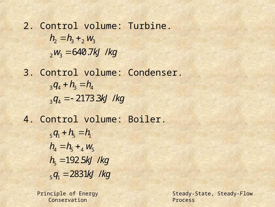
2. Control volume: Turbine.
3. Control volume: Condenser.
4. Control volume: Boiler.
2 3 2 3
2 3 640.7 /
h h w
w kJ kg
3 4 3 4
3 4 2173.3 /
q h h
q kJ kg
5 1 5 1
4 5 4 5
5
5 1
192.5 /
2831 /
q h h
h h w
h kJ kg
q kJ kg
Steady-State, Steady-Flow Process

Principle of Energy Conservation
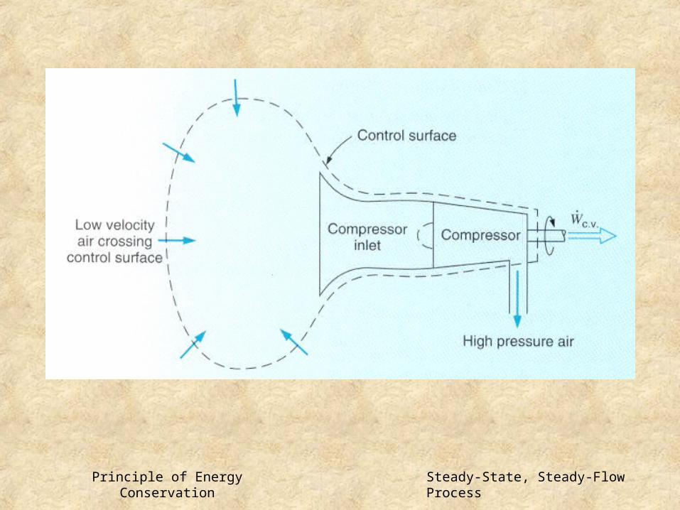
Example 5.14The centrifugal air compressor of a gas turbine receivesair from the ambient atmosphere where the pressure is 1bar and the temperature 300K. At the discharge of thecompressor the pressure is 4bar, the temperature is 480K, and the velocity is 100m/s. The mass rate of flow into the compressor is 15 kg/s. Determine the power required to drive the compressor.
We consider a control volume around the compressor, and locate the control volume at some distance from the compressor so that the air crossing the control surface has a very low velocity and is essentially at ambient conditions.
Steady-State, Steady-Flow Process

Principle of Energy Conservation
If we located our control volume directly across the
inlet section, it would be necessary to know the temperature and velocity at the compressor
inlet.
Inlet and exit states: Both states fixed.Process: SSSF.Model: Ideal gas with constant specific heat, value from Table A.10(300K)
Steady-State, Steady-Flow Process
Principle of Energy Conservation Steady-State, Steady-Flow Process

Principle of Energy Conservation
A more accurate model for the behavior of the air in this process would be the ideal gas and air tables,A.12.
2
2 2
0
. .
2
185.6 /2 2
2784
ei e
e ee i p e i
c v
Vh h w
V Vw h h C T T kJ kg
W kW
2
. .
300.19 /
482.48 /
187.3 /2
2810
i
e
ee i
c v
h kJ kg
h kJ kg
Vw h h kJ kg
W kW
Steady-State, Steady-Flow Process

Principle of Energy Conservation
Uniform State, Uniform Flow(USUF) Process
1. CV at rest.2. Uniform state in CV. May change with time.3. SS for the state of mass across the CS. Mass flow rates may change with time. 2 1 . .
0e ic vm m m m
2 2
. .
2 22 1
2 2 2 1 1 1 . .
. .
2 2
2 2
i ec v i i i e e e
c v
c v
V VQ m h gz m h gz
V Vm u gz m u gz W
5.4 Uniform-State, Uniform-Flow Process
Uniform-State, Uniform-Flow Process

Principle of Energy Conservation
Example 5.15Steam at 800kPa, 300C is throttled to 200kPa.
Changes in kinetic energy are negligible for this process. Determine the final temperature of the steam, and
the average Joule-Thomson coefficient.
Control volume: Throttle valve.Inlet state: Pi, Ti known; state fixed.
Exit state: Pe known.
Process: SSSF.Model: Steam tables.
Uniform-State, Uniform-Flow Process

Principle of Energy Conservation
3056.5 /
200
292.4
0.0127 /
i e
e
oe
J avh
h h kJ kg
P kPa
T C
TK kPa
P
Uniform-State, Uniform-Flow Process

Principle of Energy Conservation
Example 5.16Consider the throttling process across the expansion valveor through the capillary tube in a vapor-compression refrigeration cycle. In this process the pressure of the refrigerant drops from the high pressure in the condenser to the low pressure in the evaporator, and during this process some of the liquid flashes into vapor. If we consider this process to be adiabatic, the quality of the refrigerant entering the evaporator can be calculated.Consider the following process, in which ammonia is the refrigerant. The ammonia enters the expansion valve at a pressure of 1.50MPa and a temperature of 32C. Its pressure on leaving the expansion valve is 268kPa.
Uniform-State, Uniform-Flow Process

Principle of Energy Conservation
Calculate the quality of the ammonia leaving the expansion valve.
Control volume: Expansion valve or capillary tube.Inlet state: Pi, Ti known; state fixed.
Exit state: Pe known.
Process: SSSF.Model: Ammonia tables.
332.6 /
0.1585 15.85%i e
e
h h kJ kg
x
Uniform-State, Uniform-Flow Process

Principle of Energy Conservation
Example 5.17Steam at a pressure of 1.4MPa, 300C is flowing in a pipe. Connected to this pipe through a valve is an evacuated tank. The valve is opened and the tank fills with steam until the pressure is 1.4MPa, and then the valve is closed.The process takes place adiabatically and kinetic energiesand potential energies are negligible. Determine the final temperature of the steam.
Control volume: Tank.Initial state(in tank): Evacuated, mass m1=0.
Final state: P2 known.
Inlet state: Pi, Ti (in tank) known.
Process: USUF.
Uniform-State, Uniform-Flow Process

Principle of Energy Conservation
Flow into an evacuated vessel-control volume analysis
Uniform-State, Uniform-Flow Process

Principle of Energy Conservation
The temperature corresponding to a pressure of 1.4MPa and an internal energy of 3040.4kJ/kg is found to be 452C.
2 2
2
2 3040.4 /
i i
i
i
m h m u
m m
h u kJ kg
Uniform-State, Uniform-Flow Process

Principle of Energy Conservation
Example 5.18Let the tank of the previous example have a volume 0.4m3 and initially contain saturated vapor at 350kPa. The valve is then opened and steam from the line at 1.4MPa,300C flows into the tank until the pressure is 1.4MPa.Calculate the mass of steam that flows into the tank.
Control volume: Tank.Initial state: P1, saturated vapor; state fixed.
Final state: P2.
Inlet state: Pi, Ti; state fixed.
Process: USUF.Model: Steam tables.
Uniform-State, Uniform-Flow Process

Principle of Energy Conservation
2 2 1 1
2 1
2 1 2 2 1 1
2 2 1 1
32 2
2 1 12
0.4
0
i i
i
i
i i
i i
m h m u m u
m m m
m m h m u m u
m h u m h u
m v V m
Vh u m h u
v
31
1
1
0.5243 /
0.763
3040.4 /
2548.9 /i
v m kg
m kg
h kJ kg
u kJ kg
Uniform-State, Uniform-Flow Process

Principle of Energy Conservation
2
32
2
2
2 1
342
0.1974 /
2855.8 /
2.026
1.263
o
i
T C
v m kg
u kJ kg
m kg
m m m kg
Uniform-State, Uniform-Flow Process

Principle of Energy Conservation
Example 5.19A tank of 2m3 volume contains saturated ammonia at
a temperature of 40C. Initially the tank contains 50%
liquidand 50% vapor by volume. Vapor is withdrawn from
the top of the tank until the temperature is 10C.
Assuming that only vapor(i.e., no liquid) leaves and that the
processis adiabatic, calculate the mass of ammonia that is withdrawn.
Uniform-State, Uniform-Flow Process

Principle of Energy Conservation
Control volume: Tank.Initial state: T1, Vliq, Vvap; state fixed.
Final state: T2.
Exit state: Saturated vapor(temperature changing).
Process: USUF.Model: Ammonia tables.
2 2 1 1
2 1 . .
2 2 1 1 1
1462.8 /
0
0
e av
e e
ec v
e e
h kJ kg
m h m u m u
m m m
m h u m h m u
Uniform-State, Uniform-Flow Process

Principle of Energy Conservation
3
1
31
32
32
1
1
2
2
2
0.001726 /
0.0833 /
0.001601 /
0.2040 /
369.0 /
1342.7 /
226.6 /
1326.9 /
1100.3 /
f
g
f
fg
f
g
f
g
fg
v m kg
v m kg
v m kg
v m kg
u kJ kg
u kJ kg
u kJ kg
u kJ kg
u kJ kg
Uniform-State, Uniform-Flow Process

Principle of Energy Conservation
1
1
1
1
1 1 1 1
2 2 1 1 1
22 2
2 2
2
32
1 2
579.4
12.0
591.4
865100
229910
635190
2.0
0.001601 0.2040
226.6 1100.3
0.01104
0.003854 /
72.5
f
g
e
f g
e e
e
m kg
m kg
m kg
m h kJ
m u mu mu kJ
m h u m h m u kJ
Vm
v x
u x
x
v m kg
m m m kg
Uniform-State, Uniform-Flow Process

Principle of Energy Conservation
For ideal gas the internal energy is a function of the temperature only.
0
T Tv
v
T
Pdu T P dv
T
Pv RT
P R P
T v T
du
u f T
Uniform-State, Uniform-Flow Process

Principle of Energy Conservation
from specific heats.
0
2 1
2 1 0 2 1
0
2 1
p
T
T pT
T T
h h C T T
h C dT
h h h h
Uniform-State, Uniform-Flow Process

Principle of Energy Conservation
Throttling Process
SS, no work, no heat transfer, no change in PE and KE.
Joule-Thomson coefficient
T drops during throttling. T drops during throttling.
Jh
T
P
i eh h
0J 0J
Uniform-State, Uniform-Flow Process