primergy rx800 s2/s3 serveraid-8i controller -...
TRANSCRIPT

Produktfamilie
PRIMERGY RX800 S2/S3ServeRAID-8i Controller User ManualJoachim PicholFujitsu Siemens Computers GmbH Paderborn33094 Paderborne-mail: email: [email protected].: 05251 14888-18Fax: (++49) 700 / 372 00001 Sprachen: En
Edition November 2006
This manual is printed on paper treated with chlorine-free bleach.
Comments… Suggestions… Corrections…The User Documentation Department would like toknow your opinion of this manual. Your feedback helpsus optimize our documentation to suit your individual needs.
Fax forms for sending us your comments are included inthe back of the manual.
There you will also find the addresses of the relevantUser Documentation Department.
Certified documentation according to DIN EN ISO 9001:2000To ensure a consistently high quality standard anduser-friendliness, this documentation was created tomeet the regulations of a quality management system which complies with the requirements of the standardDIN EN ISO 9001:2000.
cognitas. Gesellschaft für Technik-Dokumentation mbHwww.cognitas.de
Copyright and Trademarks
© c
ogni
tas.
Ges
ells
chft
für
Tech
nik-
Dok
umen
tatio
n m
bH 2
006
Pfa
d: D
:\Akt
uelle
s_P
roje
kt\P
RIM
ER
GY
\RX
800S
3\sr
aid_
rx80
0s2-
s3_u
s\S
RA
ID_e
.vor
Copyright © 2006 Fujitsu Siemens Computers GmbH.
All rights reserved.Delivery subject to availability; right of technical modifications reserved.
All hardware and software names used are trademarks of their respective manufacturers.
Contents1 Introduction . . . . . . . . . . . . . . . . . . . . . . . . . . . . 51.1 Overview of the Documentation . . . . . . . . . . . . . . . . . . 51.2 ServeRAID-8i Features . . . . . . . . . . . . . . . . . . . . . . 61.3 Notational Conventions . . . . . . . . . . . . . . . . . . . . . . 8
2 RAID technology overview . . . . . . . . . . . . . . . . . . . . 92.1 Stripe-unit size . . . . . . . . . . . . . . . . . . . . . . . . . . . 92.2 Selecting a RAID level and tuning performance . . . . . . . . . 102.3 Supported RAID levels . . . . . . . . . . . . . . . . . . . . . 112.4 RAID level-0 . . . . . . . . . . . . . . . . . . . . . . . . . . . 122.5 RAID level-1 . . . . . . . . . . . . . . . . . . . . . . . . . . . 132.6 RAID level-1 Enhanced . . . . . . . . . . . . . . . . . . . . . 152.7 RAID level-5 . . . . . . . . . . . . . . . . . . . . . . . . . . . 162.8 RAID level-5E Enhanced . . . . . . . . . . . . . . . . . . . . 182.9 RAID level-x0 . . . . . . . . . . . . . . . . . . . . . . . . . . 202.10 Drive-state descriptions . . . . . . . . . . . . . . . . . . . . . 242.10.1 Physical-drive-state descriptions . . . . . . . . . . . . . . . . 242.10.2 Logical-drive-state descriptions . . . . . . . . . . . . . . . . . 25
3 Configuring the ServeRAID-8i . . . . . . . . . . . . . . . . . 273.1 Obtaining ServeRAID updates . . . . . . . . . . . . . . . . . . 273.2 Updating BIOS and firmware code . . . . . . . . . . . . . . . 283.3 Configuring the ServeRAID controller . . . . . . . . . . . . . . 28
4 Installing ServeRAID device drivers . . . . . . . . . . . . . 29
5 Using the ARC utility . . . . . . . . . . . . . . . . . . . . . . 315.1 Using the Array Configuration Utility . . . . . . . . . . . . . . . 325.1.1 Managing logical drives . . . . . . . . . . . . . . . . . . . . . 325.1.2 Creating logical drives . . . . . . . . . . . . . . . . . . . . . . 355.1.3 Initializing disk drives . . . . . . . . . . . . . . . . . . . . . . 385.1.4 Rescanning disk drives . . . . . . . . . . . . . . . . . . . . . 385.1.5 Using Secure Erase . . . . . . . . . . . . . . . . . . . . . . . 395.2 Using SerialSelect . . . . . . . . . . . . . . . . . . . . . . . . 405.2.1 SerialSelect options . . . . . . . . . . . . . . . . . . . . . . . 415.2.2 PHY Configuration Options . . . . . . . . . . . . . . . . . . . 435.2.3 Using the disk utilities . . . . . . . . . . . . . . . . . . . . . . 435.2.4 Viewing the event log . . . . . . . . . . . . . . . . . . . . . . 44
6 Solving ServeRAID problems . . . . . . . . . . . . . . . . . 456.1 ServeRAID controller messagess . . . . . . . . . . . . . . . . 456.2 General Problems . . . . . . . . . . . . . . . . . . . . . . . . 48
Contents
© c
ogni
tas.
Ges
ells
chft
für
Tech
nik-
Dok
umen
tatio
n m
bH 2
006
Pfa
d: D
:\Akt
uelle
s_P
roje
kt\P
RIM
ER
GY
\RX
800S
3\sr
aid_
rx80
0s2-
s3_u
s\S
RA
ID_e
.ivz
6.3 Operating System Problems . . . . . . . . . . . . . . . . . . . 506.4 Recovering from problems starting ServerView RAID . . . . . . 516.5 Recovering from an incomplete format of a physical drive . . . . 516.6 Rebuilding a defunct drive . . . . . . . . . . . . . . . . . . . . 516.6.1 Recovering from defunct drives . . . . . . . . . . . . . . . . . . 526.6.2 Rebuilding a hot-swap drive . . . . . . . . . . . . . . . . . . . 536.6.3 Restoring a logical drive configuration . . . . . . . . . . . . . . 546.7 Multiple physical drive failure recovery . . . . . . . . . . . . . . 556.7.1 Capturing the ServeRAID logs . . . . . . . . . . . . . . . . . . 556.7.2 Checking the hardware connections . . . . . . . . . . . . . . . 556.7.3 Forcing the logical drive into the Okay state . . . . . . . . . . . 56
Glossary . . . . . . . . . . . . . . . . . . . . . . . . . . . . . . . . . . 57
Related publications . . . . . . . . . . . . . . . . . . . . . . . . . . . . 67
Index . . . . . . . . . . . . . . . . . . . . . . . . . . . . . . . . . . . . 69
5
1 IntroductionThis book provides information needed to software install and configure the ServeRAID-8i SAS (Serial-Attached SCSI), RoMB (RAID on Mother Board) controller for an RX800 S2/S3 server. This high-performance, redundant array of independent disk (RAID) controller is ideally suited for data-storage environ-ments that require superior performance, flexibility, and reliable data storage.
See “ServeRAID-8i Features” on page 6 for more information on the controller.
1.1 Overview of the Documentation
I PRIMERGY manuals are available in PDF format on the ServerBooks CD which is part of the PRIMERGY ServerView Suite delivered with each server system.
The PDF files for the manuals can also be downloaded free of charge from the Internet. The overview page showing the online documentation available on the Internet can be found via the URL:http://manuals.fujitsu-siemens.com (choose: industry standard servers).
Concept and Target Group of This Manual
This book provides information for configuring the PRIMERGY RX800 S2/S3ServeRAID-8i Controller, installing device drivers, and installing and using the ServeRAID utility programs.
Hardware installation of an optional ServeRAID-8i controller for an RX800 S2/S3 extension unit is described in the RX800 S2/S3 Options Guide. The ServerView RAID software referred to in this manual is described in a sepa-rate User Manual which is based on the ServerView RAID program’s online help.
You should in the first place be familiar with the RX800 S2/S3 server system. For that purpose, please refer to the operating manual. Moreover, it is necessary to have a good knowledge of hardware and data transmission, as well as a basic knowledge of the operating system used.
Documentation Included in the Scope of Supply for the Server
The full user documentation for the PRIMERGY RX800 S2/S3 server system is listed in the operating manual which you should always have at hand. For the complete documentation overview, see also “Related publications” on page 67.

6
ServeRAID-8i Features Introduction
© c
ogni
tas.
Ges
ells
chft
für
Tech
nik-
Dok
umen
tatio
n m
bH 2
006
Pfa
d: D
:\Akt
uelle
s_P
roje
kt\P
RIM
ER
GY
\RX
800S
3\sr
aid_
rx80
0s2-
s3_u
s\S
RA
ID_e
.k01
1.2 ServeRAID-8i Features
The ServeRAID-8i controller is a SAS RoMB controller that has no independent SCSI channels. Therefore, it only works in conjunction with the onboard SAS controller. The ServeRAID-8i controller occupies a dedicated PCI-X adapter slot on the RX800 S2/S3 system board. The RAID levels supported by the controller are listed in table 1 on page 7. A 256 MB RAID Cache is also provided. A battery backup cache (BBU) is included to secure memory contents.
In the event of a power outage or failure, the BBU cache protects the data stored in the ServeRAID cache memory when using the write-back setting of the write-cache mode.
By default, the RX800 S2/S3 base unit has a single ServeRAID-8i controller installed for up to six HDDs. Optionally, a ServeRAID-8i controller is available for an RX800 S2/S3 extension unit. In a multi-node configuration, a maximum of two ServeRAID-8i controllers is allowed to handle up to 12 HDDs.
Figure 1: ServeRAID-8i controller
The ServeRAID-8i controller uses the module containing a lithium battery. Battery replacement is described in the Service Supplement.
i
Battery for Backup Cache
i

7
Introduction ServeRAID-8i Features
The standard features of the ServeRAID-8i controller are as follows:
See “RAID technology overview” on page 9 for additional information about logical drives and RAID levels.
The number of logical drives varies according to the firmware level and stripe-unit size.
The following ServeRAID software and utility programs features are supported:
The ServeRAID failover and clustering features are not supported by the ServeRAID-8i controller. Firmware update is performed via flash diskette. ServerView RAID is a module of ServerView Suite.
Battery backup cache (BBU) Yes
Cache memory 256 MB
HDDs (max.) 6
Logical drives (max.) 24
While the ServeRAID-8i can support up to 24 logical drives, it can only support 9 logical drives per physical drive. You will need 3 physical drives to create 24 logical drives.
Microprocessor Intel Verde 600 MHz
Channels/Ports 0
Transfer speed (max.) 3.0 G/s
Supported RAID levels 0, 1, 1E, 5, 5EE, 10, 50
System PCI data bus 64 bit at 66 to 133 MHz
Table 1: ServeRAID-8i controller standard features
ServerView RAID software Yes
BIOS Configuration program Yes
Copy Back Yes
Table 2: ServeRAID features supported by ServeRAID-8i controller
i
i
i

8
Notational Conventions Introduction
© c
ogni
tas.
Ges
ells
chft
für
Tech
nik-
Dok
umen
tatio
n m
bH 2
006
Pfa
d: D
:\Akt
uelle
s_P
roje
kt\P
RIM
ER
GY
\RX
800S
3\sr
aid_
rx80
0s2-
s3_u
s\S
RA
ID_e
.k01
1.3 Notational Conventions
italic type Identifies commands, menu items, names of buttons, options, variables, file names, path names and input within the body of the text.
fixed-width type Used for messages and prompts on the screen.
[Key symbols] Keys are shown as they appear on the keyboard. If an uppercase letter must be entered explicitly, the Shift key is also specified (e.g.[SHIFT]).A plus (+) sign between the key symbols indicates that these keys are to be pressed simultaneously.
bold type Used for emphasis in the body of the text.
“quotation marks” Used for references to other chapters, sections or manuals.
Ê Identifies an action that you need to take.
Alerts you to additional information, notes and tips.
CAUTION! Warning sign indicating that your health, the correct functioning of your system or the security of your data may be at risk if you ignore the information given at this point.
Table 3: Notational conventions
i
!

9
2 RAID technology overviewRedundant array of independent disks (RAID) is the technology of grouping several physical drives in a computer into one or more logical drives. Each logical drive appears to the operating system as a single drive. This grouping technique greatly enhances logical-drive capacity and performance beyond the physical limitations of a single physical drive.
When you group multiple physical drives into a logical drive, the ServeRAID controller can transfer data in parallel from the multiple drives. This parallel transfer yields data transfer rates that are many times higher than with non-grouped drives. This increased speed makes the system better able to meet the throughput (the amount of data processed in a given amount of time) or produc-tivity needs of the multiple-user network environment.
The ability to respond to multiple data requests provides not only an increase in throughput, but also a decrease in response time. The combination of parallel transfers and simultaneous responses to multiple requests enables disk drives to provide a high level of performance in network environments.
If you already understand these concepts, go to chapter “Configuring the ServeRAID-8i” on page 27.
2.1 Stripe-unit size
With RAID technology, data is striped across a group of physical drives. This data distribution scheme complements the way the operating system requests data.
The granularity at which data is stored on one drive of the logical drive before subsequent data is stored on the next drive of the logical drive is called the stripe-unit size.
You can set the stripe-unit size to 16, 32, 64, 128, 256, or 512 KB. You can maximize the performance of your ServeRAID controller by setting the stripe-unit size to a value that is close to the size of the system I/O requests. For example, performance in transaction-based environments, which typically involve large blocks of data, might be optimal when the stripe-unit size is set to 64 KB or 128 KB. However, performance in file and print environments, which typically involve multiple small blocks of data, might be optimal when the stripe-unit size is set to 16 KB.
i

10
Selecting a RAID level and tuning performance RAID technology overview
© c
ogni
tas.
Ges
ells
chft
für
Tech
nik-
Dok
umen
tatio
n m
bH 2
006
Pfa
d: D
:\Akt
uelle
s_P
roje
kt\P
RIM
ER
GY
\RX
800S
3\sr
aid_
rx80
0s2-
s3_u
s\S
RA
ID_e
.k02
The collection of stripe units, from the first drive of the logical drive to the last drive of the logical drive, is called a stripe.
2.2 Selecting a RAID level and tuning performance
Disk logical drives are used to improve performance and reliability. The amount of improvement depends on the application programs that you run on the server and the RAID levels that you assign to the logical drives.
Each RAID level provides different levels of fault-tolerance (data redundancy), utilization of physical drive capacity, and read and write performance. In addition, the RAID levels differ in regard to the minimum and maximum number of physical drives that are supported.
When selecting a RAID level for your system, consider the following factors:
RAID level
Data redun-dancy
Physical drive capacity utilization
Read perfor-mance
Write perfor-mance
Built-in sparedrive
Min. no. of drives
Max. no. of drives
Simple Volume
No 100% Superior Superior No 1 1
level-0 No 100% Superior Superior No 2 16
level-1 Yes 50% Very high
Very high No 2 2
level-1E Yes 50% Very high
Very high No 3 16
level-5 Yes 67% to 94%
Superior High No 3 16
level-5EE
Yes 50% to 88%
Superior High Yes 4 16
level-10 Yes 50% Very high
Very high No 4 16
level-50 Yes 67% to 94%
Superior High No 6 128
Table 4: Selection factors for RAID levels

11
RAID technology overview Supported RAID levels
The max. number of drives in the rightmost column is a theoretical value. Only up to six physical drives are allowed per ServeRAID-8i controller in an RX800 S2/S3 unit. With a maximum of two controllers allowed per system, up to twelve physical drives may be used.
Physical drive utilization, read performance, and write performance depend on the number of drives in the logical drive. Generally, the more drives in the logical drive, the better the performance.
2.3 Supported RAID levels
The ServeRAID-8i controller supports RAID level-0, level-1, level-1E, level-5, level-5EE, level-10, and level-50. It also supports the following additional RAID levels:
● Simple Volume — a single disk drive or segment; not redundant.
● Spanned Volume — two or more disk drives or segments with the same or different capacity, connected end-to-end. A spanned volume offers no redundancy or performance advantage over a single drive.
● RAID Volume — two or more logical drives with the same RAID level, connected end-to-end. The logical drives may have the same or different capacity and are not striped together; they may be redundant, depending on the RAID level.
Spanned volume
No 100% Superior Superior No 2 48
RAID volume
No 50% to 100%
Superior Superior No 2 48
RAID level
Data redun-dancy
Physical drive capacity utilization
Read perfor-mance
Write perfor-mance
Built-in sparedrive
Min. no. of drives
Max. no. of drives
Table 4: Selection factors for RAID levels
!
12
RAID level-0 RAID technology overview
© c
ogni
tas.
Ges
ells
chft
für
Tech
nik-
Dok
umen
tatio
n m
bH 2
006
Pfa
d: D
:\Akt
uelle
s_P
roje
kt\P
RIM
ER
GY
\RX
800S
3\sr
aid_
rx80
0s2-
s3_u
s\S
RA
ID_e
.k02
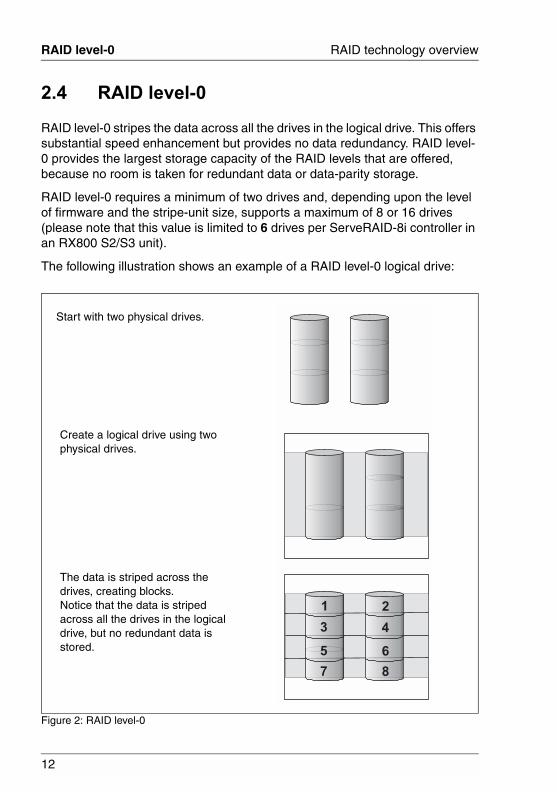
2.4 RAID level-0
RAID level-0 stripes the data across all the drives in the logical drive. This offers substantial speed enhancement but provides no data redundancy. RAID level-0 provides the largest storage capacity of the RAID levels that are offered, because no room is taken for redundant data or data-parity storage.
RAID level-0 requires a minimum of two drives and, depending upon the level of firmware and the stripe-unit size, supports a maximum of 8 or 16 drives (please note that this value is limited to 6 drives per ServeRAID-8i controller in an RX800 S2/S3 unit).
The following illustration shows an example of a RAID level-0 logical drive:
Figure 2: RAID level-0
1 2
3 4
5 6
7 8
Start with two physical drives.
Create a logical drive using two physical drives.
The data is striped across the drives, creating blocks.Notice that the data is striped across all the drives in the logical drive, but no redundant data is stored.

13
RAID technology overview RAID level-1
A physical drive failure within the logical drive results in loss of data in the logical drive assigned RAID level-0, but only in that logical drive. Logical drives assigned RAID level-1, level-1E, level-5, or level-5EE do not lose data.
When you replace a failed drive, the ServeRAID controller can rebuild all the RAID level-1, level-1E, level-5, and level-5EE logical drives automatically onto the replacement physical drive. However, any data stored in a failed RAID level-0 logical drive is lost.
Although the risk of data loss is present, you might want to assign RAID level-0 to a logical drive to take advantage of the speed this RAID level offers. You can use this logical drive to store data that you back up each day and can re-create easily. You also might want to use a RAID level-0 logical drive when you require maximum capacity.
RAID level-0 offers the following advantages and disadvantages:
2.5 RAID level-1
RAID level-1 uses data mirroring. Two physical drives are combined into a logical drive, and data is striped across the logical drive. The first half of a stripe is the original data; the second half of a stripe is a mirror (that is, a copy) of the data, but it is written to the other drive in the RAID level-1 logical drive.
RAID level-1 provides data redundancy and high levels of performance, but the storage capacity is diminished. Because the data is mirrored, the capacity of the logical drive when assigned RAID level-1 is 50% of the drive capacity.
RAID level-1 requires two physical drives.
The following illustration shows an example of a RAID level-1 logical drive:
Advantages Disadvantages
● Substantial speed enhancement
● Maximum utilization of physical drive storage capacity, because no room is taken for redundant data or data-parity storage
● No data redundancy, resulting in data loss in the event that a physical drive fails
Table 5: RAID level-0 advantages vs. disadvantages

14
RAID level-1 RAID technology overview
© c
ogni
tas.
Ges
ells
chft
für
Tech
nik-
Dok
umen
tatio
n m
bH 2
006
Pfa
d: D
:\Akt
uelle
s_P
roje
kt\P
RIM
ER
GY
\RX
800S
3\sr
aid_
rx80
0s2-
s3_u
s\S
RA
ID_e
.k02
Figure 3: RAID level-1
With RAID level-1, if one of the physical drives fails, the ServeRAID controller switches read and write requests to the remaining functional drive in the RAID level-1 logical drive.
RAID level-1 offers the following advantages and disadvantages:
Advantages Disadvantages
● 100% data redundancy
● High performance
● Allows only 50% of the physical drive storage capacity to be used
Table 6: RAID level-1 advantages vs. disadvantages
1 1
2 2
3 3
4 4
Start with two physical drives.
Create a logical drive using two physical drives.
The data is striped across the drives, creating blocks.
Notice that the data on the drive on the right is a copy of the data on the drive on the left.

15
RAID technology overview RAID level-1 Enhanced
2.6 RAID level-1 Enhanced
RAID level-1 Enhanced (RAID level-1E) combines mirroring and data striping. This RAID level stripes data and copies of the data across all of the drives in the logical drive. As with the standard RAID level-1, the data is mirrored, and the capacity of the logical drive is 50% of the drive capacity.
RAID level-1E has a similar profile to RAID level-1; it provides data redundancy and high levels of performance, but the storage capacity is diminished. However, RAID level-1E allows a larger number of physical drives to be used.
RAID level-1E requires a minimum of three drives and, depending upon the level of firmware and the stripe-unit size, supports a maximum of 8 or 16 drives (please note that this value is limited to 6 drives in an RX800 S2/S3 unit).
The following illustration is an example of a RAID level-1E logical drive:
Figure 4: RAID level-1E
1 2
6
3
5
4
1
4 6
5
3
2
*
*
**
**
Start with three physical drives.
Create a logical drive using the physical drives.
The data is striped across the drives, creating blocks.
Notice that the stripe labeled is the data stripe and the stripe labeled is the copy of the preceding data stripe. Also, notice that each block on the mirror stripe is shifted one drive.
16
RAID level-5 RAID technology overview
© c
ogni
tas.
Ges
ells
chft
für
Tech
nik-
Dok
umen
tatio
n m
bH 2
006
Pfa
d: D
:\Akt
uelle
s_P
roje
kt\P
RIM
ER
GY
\RX
800S
3\sr
aid_
rx80
0s2-
s3_u
s\S
RA
ID_e
.k02
With RAID level-1E, if one of the physical drives fails, the ServeRAID controller switches read and write requests to the remaining functional drives in the RAID level-1E logical drive.
RAID level-1E offers the following advantages and disadvantages:
2.7 RAID level-5
RAID level-5 stripes data and parity across all drives in the logical drive.
RAID level-5 offers both data protection and increased throughput. When you assign RAID level-5 to a logical drive, the capacity is reduced by the capacity of one drive (for data-parity storage). RAID level-5 gives you higher capacity than RAID level-1, but RAID level-1 offers better performance.
RAID level-5 requires a minimum of three drives and, depending upon the level of firmware and the stripe-unit size, supports a maximum of 8 or 16 drives (please note that this value is limited to 6 drives per ServeRAID-8i controller in an RX800 S2/S3 unit).
The following illustration is an example of a RAID level-5 logical drive:
Advantages Disadvantages
● 100% data redundancy
● High performance
● Allows only 50% of the physical drive storage capacity to be used
Table 7: RAID level-1E advantages vs. disadvantages

17
RAID technology overview RAID level-5
Figure 5: RAID level-5
1 2
3
5
7
4
6
8
2*
*
*
*
2
3
5
4
8
2*
*
*
1
7
6
*
Start with four physical drives.
Create a logical drive using three of the physical drives, leaving the fourth as a hot-spare drive.
The data is striped across the drives, creating blocks.Notice that the storage of the data parity (denoted by *) also is striped, and it shifts from drive to drive.A parity block (*) contains a representation of the data from the other blocks in the same stripe. For example, the parity block in the first stripe contains data representation of blocks 1 and 2.
If a physical drive fails in the logical drive, the data from the failed physical drive is recon-structed onto the hot-spare drive.

18
RAID level-5E Enhanced RAID technology overview
© c
ogni
tas.
Ges
ells
chft
für
Tech
nik-
Dok
umen
tatio
n m
bH 2
006
Pfa
d: D
:\Akt
uelle
s_P
roje
kt\P
RIM
ER
GY
\RX
800S
3\sr
aid_
rx80
0s2-
s3_u
s\S
RA
ID_e
.k02
RAID level-5 offers the following advantages and disadvantages:
2.8 RAID level-5E Enhanced
RAID level-5E Enhanced (RAID level-5EE) is the same as RAID level-5, but with a distributed spare drive and faster rebuild times. This RAID level stripes data and parity across all of the drives in the logical drive.
RAID level-5EE offers both data protection and increased throughput. When a logical drive is assigned RAID level-5EE, the capacity of the logical drive is reduced by the capacity of two physical drives (one for parity and one for the spare).
The spare drive is actually part of the RAID level-5EE logical drive, interleaved with the parity blocks, as shown in the following example. This enables data to be reconstructed more quickly if a physical drive in the logical drive fails.
RAID level-5EE requires a minimum of four drives and, depending upon the level of firmware and the stripe-unit size, supports a maximum of 8 or 16 drives (please note that this value is limited to 6 drives in an RX800 S2/S3 unit).
RAID level-5EE is also firmware-specific. The following illustration is an example of a RAID level-5EE logical drive:
Advantages Disadvantages
● 100% data protection
● Offers more physical drive storage capacity than RAID level-1 or RAID level-1E
● Lower performance than RAID level-1 and RAID level-1E
Table 8: RAID level-5 advantages vs. disadvantages

19
RAID technology overview RAID level-5E Enhanced
Figure 6: RAID level-5EE
Start with four physical drives.
Create a logical drive using all four physical drives.
The data is striped across the drives, creating blocks in the logical drive.
The storage of the data parity (denoted by *) is striped, and it shifts from drive to drive.The spare drive (denoted by S) is interleaved with the parity blocks, and it also shifts from drive to drive.
If a physical drive fails, the data from the failed drive is reconstructed. The logical drive undergoes compaction, and the distributed spare drive becomes part of the logical drive. The logical drive remains RAID level-5EE.
When you replace the failed drive, the data for the logical drive undergoes expansion and returns to the original striping scheme.
20
RAID level-x0 RAID technology overview
© c
ogni
tas.
Ges
ells
chft
für
Tech
nik-
Dok
umen
tatio
n m
bH 2
006
Pfa
d: D
:\Akt
uelle
s_P
roje
kt\P
RIM
ER
GY
\RX
800S
3\sr
aid_
rx80
0s2-
s3_u
s\S
RA
ID_e
.k02
RAID level-5EE offers the following advantages and disadvantages:
2.9 RAID level-x0
RAID level-x0 refers to RAID level-10 and level-50. RAID level-x0 uses a spanned logical drive. The operating system uses the spanned logical drive in the same way as a regular logical drive.
RAID level-x0 allows more physical drives in a logical drive. The benefits of using RAID level-x0 are larger logical drives, increased performance, and increased reliability. RAID level-0, level-1E, level-5, and level-5EE cannot use more than 16 physical drives in a logical drive; however, RAID level-10, and level-50 support 128 drives (please note that this value is limited to 6 drives per ServeRAID-8i controller in an RX800 S2/S3 unit).
RAID level-x0 requires a minimum of four drives and supports a maximum of 128 drives.
The following illustration is an example of a RAID level-10 logical drive:
Advantages Disadvantages
● 100% data protection
● Offers more physical drive storage capacity than RAID level-1 or RAID level-1E
● Higher performance than RAID level-5
● Lower performance than RAID level-1 and RAID level-1E
Table 9: RAID level-5EE advantages vs. disadvantages
21
RAID technology overview RAID level-x0
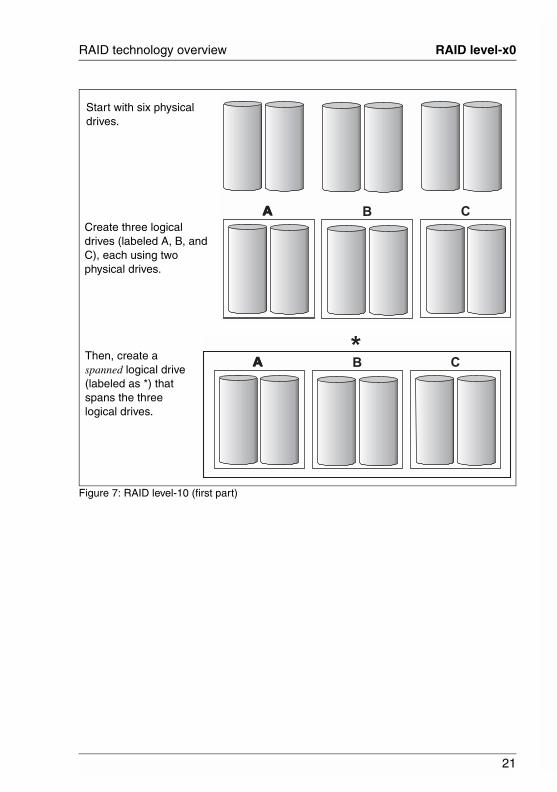
Figure 7: RAID level-10 (first part)
AA B CA
AA B CA*
Start with six physical drives.
Create three logical drives (labeled A, B, and C), each using two physical drives.
Then, create a spanned logical drive (labeled as *) that spans the three logical drives.

22
RAID level-x0 RAID technology overview
© c
ogni
tas.
Ges
ells
chft
für
Tech
nik-
Dok
umen
tatio
n m
bH 2
006
Pfa
d: D
:\Akt
uelle
s_P
roje
kt\P
RIM
ER
GY
\RX
800S
3\sr
aid_
rx80
0s2-
s3_u
s\S
RA
ID_e
.k02
Figure 8: RAID level-10 (second part)
AA B C
1
2
3
4
5
7
6
8
1
2
3
4
5
7
6
8
1
2
3
4
5
7
6
8
1
2
3
4
5
7
6
8
1
2
3
4
5
7
6
8
1
2
3
4
5
7
6
8
A*
AA B C
1
2
3
4
5
7
6
8
1
2
3
4
5
7
6
8
1
2
3
4
5
7
6
8
1
2
3
4
5
7
6
8
1
2
3
4
5
7
6
8
1
2
3
4
5
7
6
8
A
1
*
2 3
54
7
10
8
11
6
9
12
A sub-logical drive is created within each logical drive (A, B, and C). Then, the data is striped across the physical drives, creating blocks.
Notice that, in each logical drive, the data on the drive on the right is a copy of the data on the drive on the left. This is because the sublogical drives (A, B, and C) are RAID level-1 in a RAID level-10 implemen-tation (see the following table).
Then, create a logical drive within the spanned logical drive (*). The data is striped across this logical drive, creating blocks (1-12).
Notice that none of these blocks are redundant. This is because the logical drive is RAID level-0 in a RAID level-x0 implementation (see the following table).
23
RAID technology overview RAID level-x0
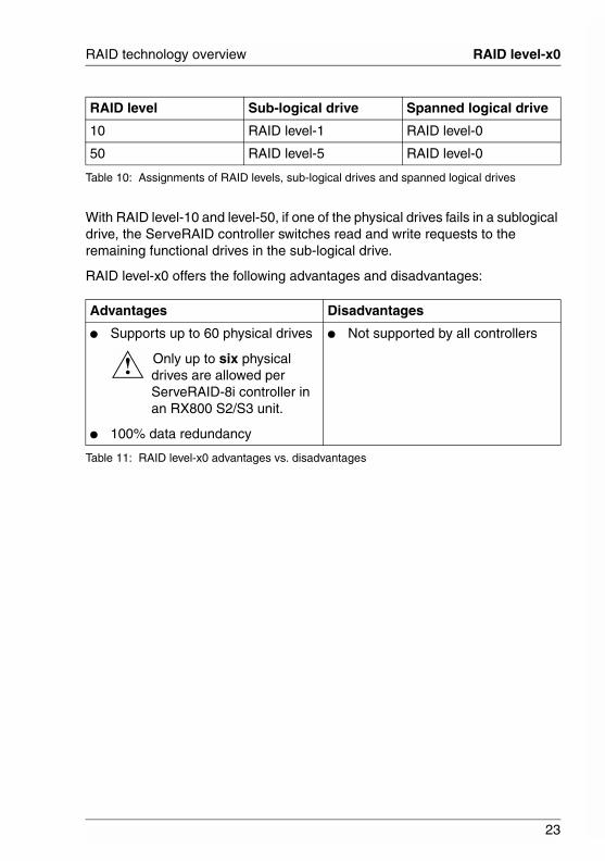
With RAID level-10 and level-50, if one of the physical drives fails in a sublogical drive, the ServeRAID controller switches read and write requests to the remaining functional drives in the sub-logical drive.
RAID level-x0 offers the following advantages and disadvantages:
RAID level Sub-logical drive Spanned logical drive
10 RAID level-1 RAID level-0
50 RAID level-5 RAID level-0
Table 10: Assignments of RAID levels, sub-logical drives and spanned logical drives
Advantages Disadvantages
● Supports up to 60 physical drives
Only up to six physical drives are allowed per ServeRAID-8i controller in an RX800 S2/S3 unit.
● 100% data redundancy
● Not supported by all controllers
Table 11: RAID level-x0 advantages vs. disadvantages
!

24
Drive-state descriptions RAID technology overview
© c
ogni
tas.
Ges
ells
chft
für
Tech
nik-
Dok
umen
tatio
n m
bH 2
006
Pfa
d: D
:\Akt
uelle
s_P
roje
kt\P
RIM
ER
GY
\RX
800S
3\sr
aid_
rx80
0s2-
s3_u
s\S
RA
ID_e
.k02
2.10 Drive-state descriptions
This section provides descriptions of the physical and logical drive states. ServeRAID publications frequently refer to these states.
2.10.1 Physical-drive-state descriptions
The following table provides descriptions of the valid physical drive states:
Drive state Meaning
Defunct A physical drive in the online, hot-spare, or rebuild state has become defunct. It does not respond to commands, which means that the ServeRAID controller cannot communicate properly with the drive.
If a physical drive has become defunct, see “Rebuilding a defunct drive” on page 51.
Hot spare A hot-spare drive is a physical drive that is defined for automatic use when a similar drive fails.
Online The drive is online. It is functioning properly and is part of a logical drive.
Rebuilding The drive is being rebuilt.
For more information on rebuilding a drive, see “Rebuilding a defunct drive” on page 51.
Ready The ServeRAID controller recognizes a ready drive as being available for definition.
Verifying Check a physical drive for inconsistent or bad data. There are two Verify actions:
● Verify without Fix: Examines each sector and block on the disk to ensure that it is readable. It does not repair the drive if bad data is found.
● Verify with Fix: Examines each sector and block on the disk to ensure that it is readable. Repairs drive if bad data is found.
Table 12: Valid physical drive states

25
RAID technology overview Drive-state descriptions
2.10.2 Logical-drive-state descriptions
The following table provides descriptions of the valid logical drive states:
Drive state Meaning
Critical migrating A logical drive in the critical state that is undergoing a logical-drive migration (LDM).
Critical A RAID level-1, level-1E, level-5, level-5EE, level-10, or level-50 logical drive that contains a defunct physical drive is in the critical state. A critical logical drive is accessible, despite a physical drive failure.
CAUTION!
If the state of the logical drive is critical, see “Rebuilding a defunct drive” on page 51.
Impacted For RAID level-1, level-1E, level-5, level-10, and level-50, if the drive fails during initialization or you stop the initial-ization process before it is complete, the drive enters the state Impacted. This means that the striping/synchroni-zation process has not completed and you need to resyn-chronize. This situation can occur in two cases:
● When creating a container, during the automatic background synchronization
● When doing data scrubbing (with background synchro-nization)
Initializing Initialization is usually automatic when you create a logical drive. Initializing a logical drive erases the first 1024 sectors on the drive and prevents access to any data previ-ously stored on the drive.
Migrating The logical drive is undergoing a logical-drive migration; that is, a change in RAID levels, a change in logical-drive size and/or change in logical drive stripe size.
Table 13: Valid logical drive states
!

26
Drive-state descriptions RAID technology overview
© c
ogni
tas.
Ges
ells
chft
für
Tech
nik-
Dok
umen
tatio
n m
bH 2
006
Pfa
d: D
:\Akt
uelle
s_P
roje
kt\P
RIM
ER
GY
\RX
800S
3\sr
aid_
rx80
0s2-
s3_u
s\S
RA
ID_e
.k02
Offline The logical drive is offline and not accessible. This state occurs when one of the following is true:
● One or more physical drives in a RAID level-0 logical drive are defunct.
● Two or more physical drives in a RAID level-1, level-1E, or level-5 logical drive are defunct.
● Three or more drives in a RAID level-5EE logical drive are defunct.
If any of these is true, see “Rebuilding a defunct drive” on page 51.
Okay The logical drive is working properly. It is in a good, functional state.
Drive state Meaning
Table 13: Valid logical drive states

27
3 Configuring the ServeRAID-8iThis chapter provides information about obtaining ServeRAID updates, updating ServeRAID BIOS and firmware code, and configuring your ServeRAID-8i controller.
3.1 Obtaining ServeRAID updates
Fujitsu-Siemens Computers (FSC) periodically makes updated versions of the ServeRAID software available from the FSC Support page on the World Wide Web.
Complete the following steps to locate files:
Ê Go to http://www.fujitsu-siemens.com/support/index_start.html.
Ê In the Search field at the top of the page, type ServeRAID; then, press Enter.
If you download ServeRAID software, you must download and install all ServeRAID software at the same time. This will ensure that all levels of the software are compatible. The ServeRAID software includes:
● BIOS and firmware code
● Device drivers
● ServerView RAID program
If you do not have access to the World Wide Web, contact your place of purchase, your FSC reseller, or your FSC marketing representative for replacement CDs.
i
28
Updating BIOS and firmware code Configuring the ServeRAID-8i
© c
ogni
tas.
Ges
ells
chft
für
Tech
nik-
Dok
umen
tatio
n m
bH 2
006
Pfa
d: D
:\Akt
uelle
s_P
roje
kt\P
RIM
ER
GY
\RX
800S
3\sr
aid_
rx80
0s2-
s3_u
s\S
RA
ID_e
.k03
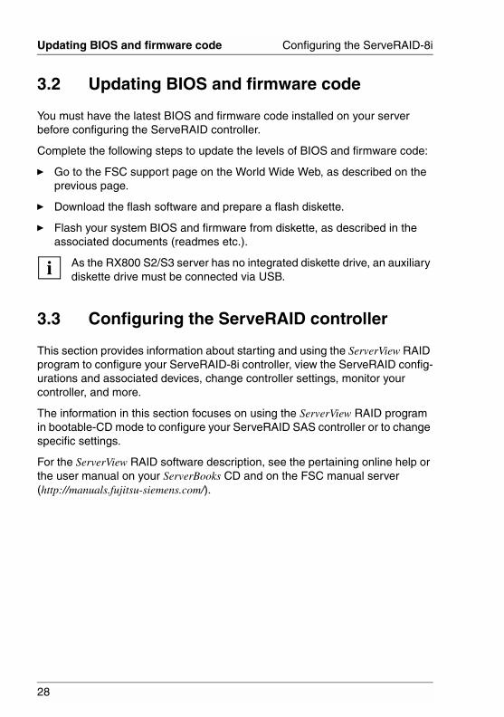
3.2 Updating BIOS and firmware code
You must have the latest BIOS and firmware code installed on your server before configuring the ServeRAID controller.
Complete the following steps to update the levels of BIOS and firmware code:
Ê Go to the FSC support page on the World Wide Web, as described on the previous page.
Ê Download the flash software and prepare a flash diskette.
Ê Flash your system BIOS and firmware from diskette, as described in the associated documents (readmes etc.).
As the RX800 S2/S3 server has no integrated diskette drive, an auxiliary diskette drive must be connected via USB.
3.3 Configuring the ServeRAID controller
This section provides information about starting and using the ServerView RAID program to configure your ServeRAID-8i controller, view the ServeRAID config-urations and associated devices, change controller settings, monitor your controller, and more.
The information in this section focuses on using the ServerView RAID program in bootable-CD mode to configure your ServeRAID SAS controller or to change specific settings.
For the ServerView RAID software description, see the pertaining online help or the user manual on your ServerBooks CD and on the FSC manual server (http://manuals.fujitsu-siemens.com/).
i

29
4 Installing ServeRAID device drivers
The ServeRAID device drivers are provided on the FSC ServerStart CD. The ServerView RAID documentation located on the ServerBooks CD provides detailed instructions for installing the device drivers on the following operating systems:
• Microsoft Windows 2000 Server and Advanced Server
• Microsoft Windows Server 2003 Standard Edition and Enterprise Edition
• Microsoft Windows Server 2003 for EM64T
• Novell NetWare 6.5
• Red Hat Enterprise Linux 3 AS/ES for 32-bit kernels
• Red Hat Enterprise Linux 3 AS/ES for EM64T 64-bit kernels
• SuSE Linux Enterprise Server 9 for 32-bit kernels
• SuSE Linux Enterprise Server 9 for EM64T 64-bit kernels
If you are configuring your startup (boot) ServeRAID controller, you must install the device driver while installing the operating system.


31
5 Using the ARC utilityThis chapter provides the information needed to start and use the Adaptec RAID Configuration (ARC) utility.
The ARC utility is an embedded BIOS utility that you can use to configure your ServeRAID-8i SAS controller. It includes:
● Array Configuration Utility (ACU)Used to create, configure, and manage logical drives. Also used to initialize and rescan drives.
● SerialSelectUsed to change device and controller settings,
● Disk UtilitiesUsed to format or verify media.
To run the ARC utility, press Ctrl+A when prompted by the following message during system startup:
Ê Press <Ctrl><A> for Adaptec RAID Configuration Utility
The ARC menu appears, presenting the following options:
● Array Configuration Utility
● SerialSelect Utility
● Disk Utilities
If there is more than one controller, a controller selection menu will appear before the ARC menu, asking that users select a controller to configure.
To select an option from this menu, or from any of the menus within ARC, browse with the arrow keys and then press Enter. In some cases, selecting an option displays another menu. To return to the previous menu at any time, press <Esc>.
The following sections discuss each of these menu options.
i

32
Using the Array Configuration Utility Using the ARC utility
© c
ogni
tas.
Ges
ells
chft
für
Tech
nik-
Dok
umen
tatio
n m
bH 2
006
Pfa
d: D
:\Akt
uelle
s_P
roje
kt\P
RIM
ER
GY
\RX
800S
3\sr
aid_
rx80
0s2-
s3_u
s\S
RA
ID_e
.k05
5.1 Using the Array Configuration Utility
The Array Configuration Utility (ACU) enables you to manage, create, and delete logical drives from the controller’s BIOS. You can also initialize and rescan drives.
You can use the ACU to create a bootable drive for the system. We recommend that you configure the system to start from a logical drive instead of a single disk to take advantage of the redundancy and performance features of logical drives. For details, see “Making a logical drive bootable” on page 33.
5.1.1 Managing logical drives
Use the Manage Arrays option to view drive properties and members, make a logical drive the boot drive, manage failover assignments, and delete logical drives. The following sections describe these operations in greater detail.
Viewing logical drive properties
To view the properties of an existing drive:
Ê At the BIOS prompt, press Ctrl+A.
Ê From the ARC menu, select Array Configuration Utility.
Ê From the ACU menu, select Manage Arrays.
Ê From the List of Arrays dialog box, select the logical drive you want to view information on and then press Enter.
– Single Level Arrays OnlyFor RAID levels 0, 1, 1E, 5, and 6, the Array Properties dialog box shows detailed information on the physical disks.
– Dual Level ArraysFor RAID levels 10, 50, and 60, highlight the displayed member to view detailed information on the physical disks, and then press Enter to display the second level. Press Enter again to display the physical disks associated with the logical drive.
A failed drive is displayed in a different text color.
Ê Press Esc to return to the previous menu.
i

33
Using the ARC utility Using the Array Configuration Utility
Making a logical drive bootable
You can make a logical drive bootable so that the system starts from the drive instead of from a stand-alone (single) disk. To make a logical drive bootable:
Ê At the BIOS prompt, press Ctrl+A.
Ê From the ARC menu, select Array Configuration Utility.
Ê From the ACU menu, select Manage Arrays.
Ê Select the logical drive you want to make bootable and then press Ctrl+B. This changes the selected drive’s number to 00, making it the controller’s boot drive.
Ê Restart the system.
● If the controller is not a boot device, you can disable its runtime BIOS (see “Runtime BIOS (Default: Enabled)” on page 42). When the BIOS is disabled, it does not occupy any of the expansion ROM region of the system’s memory map. In a system with several expansion ROMs, disabling the BIOS may be helpful.
● You cannot make a non-00 drive bootable while the drive is in a build/verify or reconfiguration process.
● The controller always uses the lowest numbered drive as its bootable drive. If you delete Drive 00 for any reason, the next lowest numbered drive becomes the bootable drive. Use the Ctrl+B option to mark the correct drive as the bootable drive (by making it Drive 00).
● If you want to boot from a stand-alone (single) disk drive, first create a volume on that disk.
● The system BIOS provides additional tools to modify the boot order. For more information, refer to your operating manual.
i

34
Using the Array Configuration Utility Using the ARC utility
© c
ogni
tas.
Ges
ells
chft
für
Tech
nik-
Dok
umen
tatio
n m
bH 2
006
Pfa
d: D
:\Akt
uelle
s_P
roje
kt\P
RIM
ER
GY
\RX
800S
3\sr
aid_
rx80
0s2-
s3_u
s\S
RA
ID_e
.k05
Deleting logical drives
CAUTION!
Back up the data on a logical drive before you delete it. When you delete the drive, you lose all your data on the drive. You cannot restore deleted drives.
To delete an existing logical drive:
Ê At the BIOS prompt, press Ctrl+A.
Ê From the ARC menu, select Array Configuration Utility.
Ê From the ACU menu, select Manage Arrays.
Ê Select the logical drive you wish to delete and then press Delete.
Ê In the Array Properties dialog box, press Delete again and then press Enter.
The following message is displayed:
Warning!! Deleting will erase all data from the array.Do you still want to continue? (Yes/No):
Ê Select Yes to delete the logical drive or No to return to the previous menu.
Ê Press Esc to return to the previous menu.
Managing hot spare drive assignments
To assign a hot spare drive to a logical drive:
Ê Select Manage Arrays from the Main menu.
Ê From the List of Arrays dialog box, select the logical drive to which you want to assign a hot spare, and then press Ctrl+S.
The Hotspare Management for Array dialog box is displayed, which shows the drives that can be assigned as hot spare drives.
Ê Select a drive and then press Insert to assign the drive as a hot spare.
The specified drive is displayed in the Assigned Hotspares drives list.
Ê Press Enter to save the hot spare drive assignment.
The following message is displayed:
Have you finished managing Hotspare drives?
Ê Press Y (for yes) to return to the Main menu.
!

35
Using the ARC utility Using the Array Configuration Utility
To remove an assigned hot spare drive from a logical drive:
Ê Select Manage Arrays from the Main menu.
Ê From the List of Arrays dialog box, select the logical drive to which you want to remove the assigned hot spare drive and press Ctrl+S.
The Hotspare Management for Array dialog box is displayed, which shows the drives that can be assigned as hot spare drives and a list of drives that are assigned as hot spare drives.
Ê From the Assigned Hotspares drives list, select the drive to be removed and then press Delete.
The specified drive is displayed in the Select Hotspares drives list.
Ê Press Enter to save the removed hot spare drive assignment.
The following message is displayed:
Have you finished managing Hotspare drives?
Ê Press Y (for yes) to return to the Main menu.
5.1.2 Creating logical drives
Before creating logical drives, make sure the disks for the drive are connected and installed in your system. Note that any disks with DOS partitions, disks with no usable space, or disks that are uninitialized appear dimmed and cannot be used for creating a new logical drive. For information on initializing a disk drive, see page 38.
To create a logical drive:
Ê Shut down and restart the system.
Ê At the BIOS prompt, press Ctrl+A.
Ê From the ARC menu, select Array Configuration Utility.
Ê From the ACU menu, select Create Array.
Ê Browse with the arrow keys to select a channel.
Ê Select the disks for the new logical drive and then press Insert.
ACU displays the largest usable space available for each disk. You can use available space from multiple disks for the new logical drive.

36
Using the Array Configuration Utility Using the ARC utility
© c
ogni
tas.
Ges
ells
chft
für
Tech
nik-
Dok
umen
tatio
n m
bH 2
006
Pfa
d: D
:\Akt
uelle
s_P
roje
kt\P
RIM
ER
GY
\RX
800S
3\sr
aid_
rx80
0s2-
s3_u
s\S
RA
ID_e
.k05
To deselect any disk, highlight the disk and then press Delete.
Note: The ACU cannot reliably find disks that were powered up after system power-up. Therefore, power up disks prior to powering up the host.
Ê Press Enter when all disks for the new logical drive are selected.
The Array Properties menu is displayed.
After you install a controller in a system and start it for the first time, the BIOS announces the configuration it has detected. This configuration may not match your system’s configuration.
CAUTION!
If you do not take any action within 30 seconds, the system automatically accepts the configuration. If the configuration does not match your system, reject it or enter the ARC utility. Otherwise, the logical drive configuration may be erased.
If necessary, enter the ARC utility. Upon entering ARC, accept the configuration that ARC reports, and then modify the configuration to suit your needs.
Assigning logical drive properties
The ACU can be used to assign logical drive properties only prior to drive creation. After the drive is created, you must use the ServerView RAID software. For more information, see the ServerView RAID online help or user manual.
To assign properties to the new drive:
Ê In the Array Properties menu, select a logical drive type and then press Enter.
The display shows only the drive types available for the number of drives selected.
The maximum number of drives allowed and minimum number of drives required depend on the RAID level, as described in the table below.
RAID level Maximum drives Minimum drives
Simple volume 16 1
RAID 0 16 2
RAID 1 2 2
RAID 1E 16 3
Table 14: Maximum und minimum numer of drives per RAID level
!

37
Using the ARC utility Using the Array Configuration Utility
The ARC utility does not support spanned volumes or RAID volumes. To create spanned and RAID volumes, use the ServerView RAID software. For that purpose, please refer to the ServerView RAID online help or user manual.
Ê Type in an optional label for the drive and then press Enter.
Ê Enter the desired drive size. The maximum size available based on the segments you selected is displayed automatically. If you want to designate a different drive size, type the desired size and select MB (megabytes), GB (gigabytes), or TB (terabytes) from the drop-down list. If the available space from the selected segments is greater than the size you specify, the remaining space is available for use in other drives.
Ê Select the desired stripe size. The allowable stripe sizes are 16, 32, 64 (the default), 128, 256, and 512 KB. The default stripe size provides the best overall performance in most network environments.
Ê Specify whether you want to enable read caching for the logical drive. When Enabled (the default), caching is enabled, providing maximum performance. When Disabled, caching is disabled. Caching should usually be enabled to optimize performance, unless your data is highly sensitive, or unless your application performs completely random reads, which is unlikely.
Ê Specify whether you want to enable write caching for the drive.
Ê When you are finished, select Done.
RAID 5 16 3
RAID 5EE 16 4
RAID 10 16 4
RAID 50 128 6
RAID level Maximum drives Minimum drives
Table 14: Maximum und minimum numer of drives per RAID level
i

38
Using the Array Configuration Utility Using the ARC utility
© c
ogni
tas.
Ges
ells
chft
für
Tech
nik-
Dok
umen
tatio
n m
bH 2
006
Pfa
d: D
:\Akt
uelle
s_P
roje
kt\P
RIM
ER
GY
\RX
800S
3\sr
aid_
rx80
0s2-
s3_u
s\S
RA
ID_e
.k05
5.1.3 Initializing disk drives
If an installed disk does not appear in the disk selection list for creating a new logical drive or if it appears grayed out, you need to initialize it before you can use it as part of a logical drive.
CAUTION!
Initializing a disk overwrites the partition table on the disk and makes any data on the disk inaccessible. If the drive is used in a logical drive, you may not be able to use the drive again. Do not initialize a disk that is part of a boot drive.
The boot drive is the lowest numbered drive (normally 00) in the List of Arrays dialog box. (See “Viewing logical drive properties” on page 32 for information on determining which disks are associated with a particular drive.)
To initialize drives:
Ê At the BIOS prompt, press Ctrl+A.
Ê From the ARC menu, select Array Configuration Utility.
Ê Select Initialize Drives.
Ê Browse with the arrow keys to select a channel.
Ê Browse with the arrow keys to highlight the disk you wish to initialize and then press Insert.
Ê Repeat the last step until all the drives to be initialized are selected.
Ê Press Enter.
Ê Read the warning message, ensure that you have selected the correct disk drives to initialize, and then press Y to continue.
5.1.4 Rescanning disk drives
To rescan the drives connected to the controller:
Ê At the BIOS prompt, press Ctrl+A.
Ê From the ARC menu, select Array Configuration Utility.
Ê Select Rescan Drives.
!

39
Using the ARC utility Using the Array Configuration Utility
5.1.5 Using Secure Erase
The Secure Erase option is used to wipe off a disk, so that the data cannot be retrieved. When this option is selected, the user is guided to select the drives to be securely erased. Only drives that are not part of a logical drive can be securely erased. While drives are undergoing Secure Erase, they are displayed in a different color and cannot be selected again for the Secure Erase option.
To use Secure Erase:
Ê At the BIOS prompt, press Ctrl+A.
Ê From the ARC menu, select Array Configuration Utility.
Ê Select Secure Erase.
Ê Browse with the arrow keys to select a channel.
Ê Browse with the arrow keys to highlight the disk you wish to securely erase and then press Insert.
Drives can only be selected for Secure Erase one at a time.
Ê Press Enter.
Ê Read the warning message, ensure that you have selected the correct disk drives for Secure Erase, and then press Y to continue.
Press Enter in the disk select menu to view the progress of the Secure Erase.
i
i

40
Using SerialSelect Using the ARC utility
© c
ogni
tas.
Ges
ells
chft
für
Tech
nik-
Dok
umen
tatio
n m
bH 2
006
Pfa
d: D
:\Akt
uelle
s_P
roje
kt\P
RIM
ER
GY
\RX
800S
3\sr
aid_
rx80
0s2-
s3_u
s\S
RA
ID_e
.k05
5.2 Using SerialSelect
SerialSelect allows you to change device and controller settings without opening the computer cabinet or handling the card. With this utility, you can modify the Channel Interface Definitions and Device Configuration Options.
To access SerialSelect:
Ê When you turn on or restart your system, press Ctrl+A to access the ARC utility when you see the following message:
Press <Ctrl><A> for Adaptec RAID Configuration Utility
Ê If multiple controllers are installed, select the controller you want to configure and then press Enter.
Ê From the ARC menu, select SerialSelect Utility.
The SAS Configuration and Controller Configuration menu options are displayed. See “SerialSelect Options” on page 41 for a list and descriptions of the options.
Ê To select a SerialSelect menu option, browse with the arrow keys to the option and then press Enter.
In some cases, selecting an option displays another menu. You can return to the previous menu at any time by pressing Esc.
Ê To restore the original SerialSelect default values, press F6 from the SAS Configuration or the Controller Configuration menu.
Ê To exit SerialSelect, press Esc until a message prompts you to exit. (If you changed any host adapter settings, you are prompted to save the changes before you exit.) Select Yes to exit and restart the system. Any changes you made take effect after the system boots.
i

41
Using the ARC utility Using SerialSelect
5.2.1 SerialSelect options
The following table lists the available and default settings for each SerialSelect option followed by the descriptions of each option:
The default settings are appropriate for most systems and it is recom-mended that you do not change the settings.
SerialSelect Options Available Settings Default Setting
Controller Configuration
Drives Write Cache Enabled
Disabled
Drive Default
Drive Default
Runtime BIOS Enabled
Disabled
Enabled
Automatic Failover Enabled
Disabled
Enabled
Array Background Consistency Check
Enabled
Disabled
Enabled
BBS Support Enabled
Disabled
Enabled
Array based BBS Support
Enabled
Disabled
Disabled
Physical Drives Display During Post
Enabled
Disabled
Disabled
PHY Configuration
PHY Rate Auto, 1.5, 3.0 Auto
CRC Checking Yes, No No (Disabled)
SAS Address 0-15 8
Table 15: Settings for SerialSelect options
i

42
Using SerialSelect Using the ARC utility
© c
ogni
tas.
Ges
ells
chft
für
Tech
nik-
Dok
umen
tatio
n m
bH 2
006
Pfa
d: D
:\Akt
uelle
s_P
roje
kt\P
RIM
ER
GY
\RX
800S
3\sr
aid_
rx80
0s2-
s3_u
s\S
RA
ID_e
.k05
Drives Write Cache (Default: Drive Default)
This option controls the drive performance. When Enabled, write cache is enabled and it provides maximum driver performance. When Disabled, no write cache is used on the drive. By default, the drive’s setting is used.
When Enabled, there is a slight possibility (less than the controller cache) of data loss or corruption during a power failure.
Runtime BIOS (Default: Enabled)
This option controls the state of the BIOS at POST time. When Enabled, the controller BIOS allows the controller to act as a bootable device. Disabling the BIOS allows another suitable controller to act as the boot device.
Automatic Failover (Default: Enabled)
This function controls the rebuilding of a logical drive when a failed drive is replaced. When Enabled, the controller automatically rebuilds a drive when the failed drive is replaced. When Disabled, the logical drive must be rebuilt manually.
Array Background Consistency Check (Default: Enabled)
This function controls the media verification for all logical drive types. When Enabled, the controller continuously performs read verification on all logical drives to check disk medium integrity. In case a medium error is encountered, the repair process will be performed on redundant logical drives. Consistency checking processes reduce performance, especially under a heavy I/O load.
BBS Support (Default: Enabled)
This function controls whether the BIOS acts as a plug-and-play BIOS or a non-plug-and-play BIOS. When Enabled (default), it will install int13h drives in the second phase of the BBS. When Disabled, it will install int13h at POST time.
Array based BBS Support (Default: Disabled)
When Enabled in systems that support BBS, the controller presents attached bootable devices up to the host system's BIOS for boot device selection. This is relevant for logical drives.
i

43
Using the ARC utility Using SerialSelect
Physical Drives Display During POST (Default: Disabled)
When Enabled, attached physical devices are displayed during system POST. Displaying the devices adds a few seconds to the overall POST time.
5.2.2 PHY Configuration Options
PHY Rate (Default: Auto)
The data transfer rate between the controller and devices. The default setting is Auto(matic), which allows the SAS card to adjust the speed as needed.
CRC Checking (Default: No)
Determines whether the controller verifies the accuracy of data transfer on the Serial bus. CRC Checking should be disabled on the controller and all devices if any device supported by the controller does not support CRC Checking.
SAS Address (Default: 8)
Specifies the 64-bit SAS address of the PHY using a globally unique worldwide name (WWN) identifier.
5.2.3 Using the disk utilities
The disk utilities enable you to low-level format or verify the media of your Serial Attached SCSI hard disks. To access the disk utilities:
Ê Turn on your computer and then press Ctrl+A when prompted to access the ARC utility.
Ê If multiple controllers are installed, select the controller you want to configure and then press Enter.
Ê From the ARC menu, select Disk Utilities.
Ê Select the desired disk and then press Enter.

44
Using SerialSelect Using the ARC utility
© c
ogni
tas.
Ges
ells
chft
für
Tech
nik-
Dok
umen
tatio
n m
bH 2
006
Pfa
d: D
:\Akt
uelle
s_P
roje
kt\P
RIM
ER
GY
\RX
800S
3\sr
aid_
rx80
0s2-
s3_u
s\S
RA
ID_e
.k05
You are offered the following options:
– Format DiskSimulates a format of the hard drive by removing the file system and writing zeros to the entire disk. SAS drives are formatted at the factory and do not need to be formatted again.
CAUTION!
Formatting destroys all data on the drive. Be sure to back up your data before performing this operation.
– Verify Disk MediaScans the media of a disk drive for defects. Any errors found are corrected.
5.2.4 Viewing the event log
The BIOS-based event log stores all firmware events (configuration changes, drive creation, boot activity, and so on).
The event log has a fixed size. Once full, old events are flushed as new events are stored. Also, the log is volatile; therefore, it is cleared after each system restart.
To access the event log:
Ê When you turn on or restart your system, press Ctrl+A to access the ARC when prompted by the following message:
Press <Ctrl><A> for Adaptec RAID Configuration Utility
Ê If multiple controllers are installed, select the controller you want to configure and then press Enter.
Ê From the ARC menu, press Ctrl+P.
The Controller Service Menu appears.
Ê Select Controller Log Information and then press Enter.
The current log is displayed.
!

45
6 Solving ServeRAID problemsThis chapter provides basic troubleshooting information to help you resolve some common problems that might occur with your ServeRAID-8i controller. This section also describes the ServeRAID text that might be displayed during startup. Moreover, it includes some basic information about rebuilding a defunct drive.
CAUTION!
When you are working inside the server, please observe the safety notes in the “Safety” manual and in the operating manual (chapter “Important Notes”), especially when you connect or disconnect cables, check cable connections, or replace disk drives.
6.1 ServeRAID controller messagess
This section lists the ServeRAID messages that might appear during system startup.
All physical drives contain unique identifiers, such as the drive serial number and manufacturer. During configuration, the ServeRAID controller stores this information.
The following table lists the messages associated with the ServeRAID subsystem listed in alphabetical order:
Message Explanation Action
No INT 13h device Found Drives are not seen by the BIOS, although they are connected.
Either the drives are not powered or the cables are not intact.
Ê You must check the power and data cable connections
Table 16: ServerRAID controller messages
!
46
ServeRAID controller messagess Solving ServeRAID problems
© c
ogni
tas.
Ges
ells
chft
für
Tech
nik-
Dok
umen
tatio
n m
bH 2
006
Pfa
d: D
:\Akt
uelle
s_P
roje
kt\P
RIM
ER
GY
\RX
800S
3\sr
aid_
rx80
0s2-
s3_u
s\S
RA
ID_e
.k06
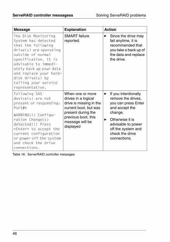
The Disk Monitoring System has detected that the following drive(s) are operating outside of normal specification. It is advisable to immedi-ately back up your data and replace your hard-disk drive(s) by calling your service representative.
SMART failure reported.
Ê Since the drive may fail anytime, it is recommended that you take a back up of the data and replace the drive.
Following SAS device(s) are not present or responding: Port#n
WARNING!!! Configu-ration Change(s) detected!!! Press <Enter> to accept the current configuration or power off the system and check the drive connections.
When one or more drives in a logical drive is missing in the current boot, but was present during the previous boot, this message will be displayed
Ê If you intentionally remove the drives, you can press Enter and accept the change.
Ê Otherwise it is advisable to power off the system and check the drive connections.
Message Explanation Action
Table 16: ServerRAID controller messages

47
Solving ServeRAID problems ServeRAID controller messagess
A logical drive that was connected to this port is missing. However a different drive is connected to the same port: Port#n
WARNING!!! Configu-ration Change(s) detected!!! Press <Enter> to accept the current configuration or power off the system and check the drive connections.
When one or more drives are missing, but replaced with a different drive in place of a missing drive.
Ê If you intentionally remove the drives, you can press Enter and accept the change.
Ê Otherwise it is advisable to power off the system and check the drive connections.
Following SAS drive(s) are moved to different port(s) Port#m to Port#n
When one or more drives are moved around the system. For example, if the drive in port#0 is moved to port#1.
It is just a notification message and the BIOS automatically updates the configuration. No user interaction needed.
BIOS is Disabled If the BIOS Int 13h support is disabled in the Ctrl+A, you will not be able to see any drives.
Ê You have to enable the INT13h support inside the Ctrl+A SASSelect Controller configuration menu.
This message will only appear with supported platforms.
Message Explanation Action
Table 16: ServerRAID controller messages
i

48
General Problems Solving ServeRAID problems
© c
ogni
tas.
Ges
ells
chft
für
Tech
nik-
Dok
umen
tatio
n m
bH 2
006
Pfa
d: D
:\Akt
uelle
s_P
roje
kt\P
RIM
ER
GY
\RX
800S
3\sr
aid_
rx80
0s2-
s3_u
s\S
RA
ID_e
.k06
6.2 General Problems
The following tables describe general problems you might encounter, along with suggested solutions:
Problem Suggested solution
System does not boot from SAS controller.
Ê Check the system basic input/output system (BIOS) configuration for PCI interrupt assignments.
Ê Make sure a unique interrupt is assigned for the RAID controller.
Ê Initialize the logical drive before installing the operating system.
One of the hard drives in the logical drive fails.
Ê Check the SAS cables.
Ê If the SAS Cables are OK, replace the drive.
A drive at a specific SAS ID fails repeatedly.
Ê Replace the SAS cable.
After pressing Ctrl+A during bootup and trying to make a new configuration, the system hangs.
Ê Replace the drive cable.
Pressing Ctrl+A does not display a menu.
Ê A color monitor is required to display the BIOS utility menus.
At system POST (Power On Self Test) with the RAID controller installed, the BIOS banner display is garbled or does not appear at all.
Ê Remove power from the system and verify that the RAID controller cache memory is properly installed.
Ê If the symptom persists, contact your FSC service representative for further assistance.
Table 17: General problems

49
Solving ServeRAID problems General Problems
The logical drive status is displayed as Degraded. This is displayed next to the logical drive name during the POST.
This could be due to one of the following:
● One of the members is failed (meaning IO failed).
● One of the member drives is missing.
● User forcibly failed a member in the OS application.
The logical drive can be turned back to online in any one of these ways:
Ê Enter the ACU by pressing Ctrl+A and then assign a spare if the member is missing or failed. This will automati-cally start a Rebuild operation.
Ê Insert the member back if it is missing. This will automatically start a Rebuild operation.
Two degraded logical drives are seen during the POST display along with the following message:
Warning!!! A configuration change detected!!! Following Arrays have Missing or Rebuilding or Failed Members and are critical.
This error is shown when the controller does not detect some of the logical drive members because they are either missing or failed.
The logical drives can be turned back to online in any one of these ways:
Ê If the drives are missing, re-insert the missing drives.
Ê If the drives have failed, replace them.
Ê Assign a hotspare to the degraded drive (either missing or failed).
Problem Suggested solution
Table 17: General problems
50
Operating System Problems Solving ServeRAID problems
© c
ogni
tas.
Ges
ells
chft
für
Tech
nik-
Dok
umen
tatio
n m
bH 2
006
Pfa
d: D
:\Akt
uelle
s_P
roje
kt\P
RIM
ER
GY
\RX
800S
3\sr
aid_
rx80
0s2-
s3_u
s\S
RA
ID_e
.k06
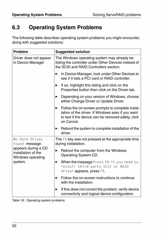
6.3 Operating System Problems
The following table describes operating system problems you might encounter, along with suggested solutions:
Problem Suggested solution
Driver does not appear in Device Manager
The Windows operating system may already be listing the controller under Other Devices instead of the SCSI and RAID Controllers section.
Ê In Device Manager, look under Other Devices to see if it lists a PCI card or RAID controller.
Ê If so, highlight this listing and click on the Properties button then click on the Driver tab.
Ê Depending on your version of Windows, choose either Change Driver or Update Driver.
Ê Follow the on-screen prompts to complete instal-lation of the driver. If Windows asks if you want to test if the device can be removed safely, click on Cancel.
Ê Reboot the system to complete installation of the driver.
No Hard Drives Found message appears during a CD installation of the Windows operating system.
The F6 key was not pressed at the appropriate time during installation.
Ê Reboot the computer from the Windows Operating System CD.
Ê When the message Press F6 if you need to install third party SCSI or RAID driver appears, press F6.
Ê Follow the on-screen instructions to continue with the installation.
Ê If this does not correct the problem, verify device connectivity and logical device configuration.
Table 18: Operating system problems

51
Solving ServeRAID problemsRecovering from problems starting ServerView
6.4 Recovering from problems starting ServerView RAID
See the ServerView RAID online help or user manual for more information.
6.5 Recovering from an incomplete format of a physical drive
During formatting of a physical drive, if the format process is stopped by a system reset, system shutdown, power outage, or by some other means, the physical drive becomes inoperable.
Complete the following steps to enable the physical drive to communicate with the ServeRAID controller again:
Ê Note the port of the ServeRAID controller to which the physical drive is connected.
Ê Press Ctrl+A at POST and use the Disk Utilities to format the disk (see “Using the disk utilities” on page 43).
Ê After the format process is complete, the ServeRAID controller will be able to recognize the drive again.
6.6 Rebuilding a defunct drive
A physical drive is marked defunct when there is a loss of communication between the controller and the physical drive. This can be caused by any of the following conditions:
● An improperly connected cable, physical drive, or controller
● Loss of power to a drive
● A defective cable, backplane, physical drive, or controller
In each case, after the communication problem is resolved, a rebuild operation is required to reconstruct the data for the device in its disk drive. The ServeRAID controllers can reconstruct RAID level-1, level-1E, level-5, level-5EE, level-10, and level-50 logical drives. They cannot, however, reconstruct data stored in RAID level-0 logical drives because RAID level-0 is not redundant. If a logical drive contains only RAID level-0 logical drives, the logical drives are marked

52
Rebuilding a defunct drive Solving ServeRAID problems
© c
ogni
tas.
Ges
ells
chft
für
Tech
nik-
Dok
umen
tatio
n m
bH 2
006
Pfa
d: D
:\Akt
uelle
s_P
roje
kt\P
RIM
ER
GY
\RX
800S
3\sr
aid_
rx80
0s2-
s3_u
s\S
RA
ID_e
.k06
offline, and the logical drives contain damaged data. You cannot rebuild the logical drives. You must correct the cause of the failure or replace the physical drives; then, you must restore your data.
To prevent data-integrity problems, the ServeRAID controllers set the RAID level-0 logical drives in the affected logical drive to blocked during the rebuild operation for RAID level-1, level-1E, or level-5. After the rebuild operation is completed, you can unblock the RAID level-0 logical drives and access them again. Remember, however, that the RAID level-0 logical drives contain damaged data.
6.6.1 Recovering from defunct drives
If the defunct drives are not part of a logical drive, contact your FSC service representative.
If a physical drive fails in a logical drive or multiple physical drives fail in separate logical drives (one physical drive per logical drive), complete the following steps:
Ê Replace each defunct physical drive.
The ServeRAID controller starts the rebuild operation when it detects the removal and reinsertion of a drive that is part of a logical drive.
(For a configuration that contains a hot-spare drive) If you replace a failed physical drive, it is not necessary to position the new physical drive on the same SAS ID as the original hot-spare drive. The replacement physical drive is automatically incorporated into the configuration as a hot-spare drive. Here is an example of how this works:
– The original configuration consists of a RAID level-5 logical drive composed of three physical drives. The physical drives are assigned SAS IDs 0, 1, and 2. SAS ID 3 is a hot-spare drive.
– The physical drive at SAS ID 2 fails; the logical drive enters the critical state.
– The hot-spare drive at SAS ID 3 is rebuilt into the logical drive.
– You remove the failed physical drive at SAS ID 2, and replace it with a new physical drive. The new physical drive at SAS ID 2 is automatically assigned to be a hot-spare drive.
Ê If a rebuild operation is in progress, wait until the rebuild is complete. Otherwise, go to the next step.
i

53
Solving ServeRAID problems Rebuilding a defunct drive
If you are replacing multiple defunct drives, you must wait for each rebuild operation to complete before starting subsequent rebuild operations.
Ê Verify the cables, physical drives, and controllers are installed properly.
Ê Attempt to rebuild the defunct physical drive by performing a hot-swap rebuild. See “Rebuilding a hot-swap drive” on page 53 for instructions.
Ê If the hot-swap rebuild fails, contact your FSC service representative.
6.6.2 Rebuilding a hot-swap drive
A hot-swap rebuild refers to a rebuild operation that is started by the ServeRAID controller when it detects that a drive that is part of a logical drive and in the defunct state has been removed and reinserted on the SAS cable or backplane. The reinsertion of the physical drive, whether it is the same drive or a new drive, will trigger the ServeRAID controller to start the rebuild operation. During the rebuild operation, the drive being rebuilt is in the rebuild state, and the logical drive remains critical until the rebuild operation has been successfully completed.
On FSC servers, when a hot-spare drive is available, the rebuild operation begins automatically without the need to replace the failed drive. If more than one drive fails within the same logical drive, no rebuild takes place. If multiple drives fail in separate logical drives (one physical drive per logical drive), the controller initiates a rebuild operation for the logical drives within the logical drive containing the first failed physical drive. This rebuild operation is performed on the first hot-spare drive of sufficient size to become a valid member of the logical drive.
Complete the following steps to start a hot-swap rebuild:
Ê Without removing the drive completely, gently remove the physical drive from the server, using the handle of the hot-swap tray. If necessary, see the operating manual on the ServerBooks CD that comes with your server for information about removing a physical drive.
Ê Wait 20 seconds to allow the physical drive to completely stop spinning.
Ê If you are certain there is nothing wrong with the physical drive you removed, gently reinstall the drive into the server. Make sure the drive is completely installed in the backplane connector.
i

54
Rebuilding a defunct drive Solving ServeRAID problems
© c
ogni
tas.
Ges
ells
chft
für
Tech
nik-
Dok
umen
tatio
n m
bH 2
006
Pfa
d: D
:\Akt
uelle
s_P
roje
kt\P
RIM
ER
GY
\RX
800S
3\sr
aid_
rx80
0s2-
s3_u
s\S
RA
ID_e
.k06
Ê Otherwise, replace the physical drive with a new drive that is the same size (or larger) and continue with the rebuild operation.
– If multiple drives fail in separate logical drives (one physical drive per logical drive), replace each defunct physical drive. If multiple physical drives fail at the same time within the same logical drive, contact your FSC service representative.
– Although it is possible to rebuild a defunct physical drive to an online physical drive that is defective, avoid doing so.
6.6.3 Restoring a logical drive configuration
If copy back is enabled on your system, the ServeRAID software restores a logical drive to its original configuration after you replace a failed drive in a logical drive. The copy back operation restores the data to its previous location, before the logical drive was rebuilt from its spare.
To enable or disable copy back, use the ServerView RAID software. By default, copy back starts automatically when the ServeRAID controller detects that a failed drive in a logical drive is replaced.
When you upgrade the ServeRAID software from a previous release, copy back is disabled by default.
For more information, see the ServerView RAID online help or user manual.
i
i
55
Solving ServeRAID problems Multiple physical drive failure recovery
6.7 Multiple physical drive failure recovery
● This section only applies to the Windows operating system.
● There is no guarantee that this procedure will recover data.
● You must have all of the physical drives in order to restore the logical drive to the okay state. This procedure will not restore critical or degraded logical drives.
● Repeat this procedure for each logical drive that is marked offline.
The ServeRAID controller is designed to tolerate a single physical drive failure in a logical drive. Although there is no guarantee that any data can be recovered after a logical drive transitions to the offline state, the following procedure offers the possibility of a successful recovery.
This procedure involves the following steps:
● Capturing the ServeRAID logs
● Checking the hardware connections
● Forcing the logical drive into the Okay state
6.7.1 Capturing the ServeRAID logs
Use the ServerView RAID software to capture the ServeRAID logs. For more information, see the ServerView RAID online help or user manual.
6.7.2 Checking the hardware connections
While the server is turned off, complete the following tasks:
Ê Reseat the ServeRAID controllers.
Ê Reseat the cables and the disks against the backplanes.
Ê Reseat the power cables to the backplane and SAS backplane repeater options, if they are present.
As you are reseating the components, visually inspect each piece for bent pins, nicks, crimps, pinches, or other signs of damage. Take extra time to ensure that each component snaps or clicks into place properly.
i

56
Multiple physical drive failure recovery Solving ServeRAID problems
© c
ogni
tas.
Ges
ells
chft
für
Tech
nik-
Dok
umen
tatio
n m
bH 2
006
Pfa
d: D
:\Akt
uelle
s_P
roje
kt\P
RIM
ER
GY
\RX
800S
3\sr
aid_
rx80
0s2-
s3_u
s\S
RA
ID_e
.k06
6.7.3 Forcing the logical drive into the Okay state
Use the ServerView RAID software to force the logical drive into the Okay state:
Ê In ServerView RAID, right-click the offline logical drive.
Ê Select the Force online option.
If the Force online option does not appear or is greyed out, you do not have all of the necessary physical drives attached to the controller and you will not be able to complete this procedure.
See the ServerView RAID online help or user manual for more infor-mation.
i

57
Glossaryauto-synchronization
Synchronization on RAID level-5 and level-50 drives that is automatically initiated when logical drives are created. This type of synchronization works in the background.
battery backup cache (BBU)Buffer storage that protects data during write-back operations; in the event of a power failure, it preserves the data in the controller cache.
block A data unit created when data is striped across physical drives.
compactionThe process by which a RAID level-5EE logical drive utilizes the distributed spare drive in the event of a physical drive failure. After the data is reconstructed, the original logical drive undergoes compaction, and the distributed spare drive becomes part of the new logical drive. The logical drive remains RAID level-5EE.
controllerA device that coordinates and controls the operation of one or more input/output devices, such as workstations, and synchronizes the operation of such devices with the operation of the system as a whole.
copy backA method of restoring a logical drive’s original configuration after replacing a failed drive in a logical drive.
criticalThe state of a RAID level-1, level-1E, level-5, level-5EE, level-10, or level-50 logical drive that contains one defunct drive.
data mirroringA technique that creates a single logical drive from two physical drives. All data written to the logical drive is written to both physical drives, creating a pair of physical drives containing exactly the same data.

58
Glossary
© c
ogni
tas.
Ges
ells
chft
für
Tech
nik-
Dok
umen
tatio
n m
bH 2
006
Pfa
d: D
:\Akt
uelle
s_P
roje
kt\P
RIM
ER
GY
\RX
800S
3\sr
aid_
rx80
0s2-
s3_u
s\S
RA
ID_e
.mix
data scrubbingA feature that provides automatic, continuous synchronization during system use. This feature works in the background, and ensures that the redundant data and/or parity is correct.
data stripingA technique that divides a logical drive into data blocks, called stripes, which are then distributed over the physical drives. The layout is such that a sequential read of data on the logical drive results in parallel reads to each of the physical drives, resulting in improved performance.
defunctA physical-drive state in which the ServeRAID controller cannot commu-nicate properly with the drive.
distributed spare driveIn RAID level-5EE, the logical drive designated as a spare drive. Because this spare drive is spread over several physical drives, it is described as distributed.
expansionThe process by which a compacted logical drive returns to its original striping scheme, after a failed drive is replaced in a RAID level-5EE logical drive. Contrast with compaction.
fault toleranceThe abililty of a computer system to operate correctly even though one or more of its component parts are malfunctioning.
firmwareProprietary code that is usually delivered as microcode as part of an operating system. Firmware is more efficient than software loaded from an alterable medium and more adaptable to change than pure hardware circuitry. An example of firmware is the Basic Input/Output System (BIOS) in read-only memory (ROM) on a PC system board.

59
Glossary
flashcopyA point-in-time capture of logical drive data on a direct attached storage device. If an error occurs in the original logical drive, you can roll-back the logical drive to the point when the FlashCopy was created.
hot-spare driveA physical drive that is defined for automatic use when a similar drive fails.
hot-swappablePertaining to a component that can be removed or replaced while the system is running.
hot-swap rebuildAn operation that is started by the ServeRAID controller when it detects that a physical drive that is part of a logical drive and in the defunct state has been removed and replaced on a SCSI cable or backplane.
impactedA fault tolerant logical drive moves to the Impacted state if a drive fails during initialization or the initialization process is stopped before it completes. This may occur during auto-synchronization or data scrubbing (with background synchronization). In an impacted drive, the striping/synchronization process has not completed and you need to resynchronize.
initialize logical drive In the ServeRAID utilities, to erase the first 1024 sectors on a drive, preventing access to any data previously stored on the drive.
logical driveA grouping of physical drives that the operating system recognizes as a single drive.
logical-drive migration. To add or remove physical drives from an existing logical drive, to change RAID levels, change logical-drive size, or effect an increase in free space.
migratingThe state of a logical drive undergoing a logical-drive migration.
60
Glossary
© c
ogni
tas.
Ges
ells
chft
für
Tech
nik-
Dok
umen
tatio
n m
bH 2
006
Pfa
d: D
:\Akt
uelle
s_P
roje
kt\P
RIM
ER
GY
\RX
800S
3\sr
aid_
rx80
0s2-
s3_u
s\S
RA
ID_e
.mix
mirror roleThe role assigned to the two physical drives that an integrated RAID controller uses to create a RAID level-1 logical drive. When the logical drive is created, data is copied from the primary physical drive to the secondary physical drive. Any data on the secondary drive is destroyed.
Notification ManagerA tool used to notify remote systems of events, problems, and configu-ration changes occurring on a local system.
offlineA logical-drive state in which the logical drive is inaccessible.
okayA logical-drive state in which the logical drive is functional.
onlineA physical-drive state in which the physical drive is functioning properly and is part of a logical drive.
parityA characteristic of the data stored on a RAID level-5, level-5EE, or level-50 logical drive that can be used, in conjunction with the data on the remaining drives, to recreate data on a failed physical drive.
parity blockIn a RAID level-5, level-5EE, or level-50 logical drive, a data unit that contains a representation of the data from other blocks in the same stripe.
physical driveA hard disk drive.
POSTPower-on self-test. During POST, the ServeRAID controller compares the stored configuration information to the configuration that is actually present. If a discrepancy exists, one or more status messages appear after the POST completes but before the operating system loads.
61
Glossary
RAIDA technology of grouping several physical drives in a computer into a logical drive. Each logical drive appears to the operating system as a single drive. This grouping technique greatly enhances logical-drive capacity and performance beyond the physical limitations of a single physical drive.
RAID level-0A RAID level that uses data striping to distribute data evenly across physical drives. While it enables full utilization of physical drive capacity and performance acceleration, RAID level-0 provides neither fault tolerance nor redundancy.
RAID level-1A RAID level that uses data mirroring to distribute data across two physical drives. It provides data redundancy and performance acceler-ation, although the usable physical drive space is reduced by 50 percent.
RAID level-1EA RAID level that uses both data striping and data mirroring to distribute data across three or more physical drives. Data is striped across each disk in the logical drive; the first set of stripes are the data stripes, and the second sets of stripes are mirror copies of the first stripe, shifted one drive. It provides data redundancy and performance acceleration, although the usable physical drive space is reduced by 50 percent.
RAID level-5A RAID level that uses data striping and block interweaving to distribute data across three or more physical drives. It provides full data protection and performance acceleration, although only 67-94% of physical drive storage capacity can be used.
RAID level-5EEA RAID level that uses data striping and block interweaving to more efficiently distribute data across four or more physical drives. It uses some space on each physical drive as a distributed hot-spare. However, RAID level-5EE offers a more efficient distributed spare drive and faster rebuild times. The spare drive is actually part of the RAID level-5EE logical drive.

62
Glossary
© c
ogni
tas.
Ges
ells
chft
für
Tech
nik-
Dok
umen
tatio
n m
bH 2
006
Pfa
d: D
:\Akt
uelle
s_P
roje
kt\P
RIM
ER
GY
\RX
800S
3\sr
aid_
rx80
0s2-
s3_u
s\S
RA
ID_e
.mix
A RAID level-5EE spare drive is interleaved with the parity blocks. This enables data to be reconstructed more quickly if a physical drive in the logical drive fails. RAID level-5EE provides full data protection and performance acceleration, although only 50-88% of physical drive storage capacity can be used.
RAID level-x0RAID level-10 or level-50. These RAID levels use spanned logical drives to enable the use of up to 60 physical drives.
Only up to six physical drives are allowed per ServeRAID-8i controller in an RX800 S2.
They provide full data protection, performance acceleration, and greater reliability, although only 50-94% of physical drive storage capacity can be used.
read-ahead cache modeA ServeRAID controller setting that determines whether the ServeRAID controller transfers data from disk to its local cache in increments equal to the stripe-unit size or the system I/O requests. The options are Enabled and Disabled.
read-ahead cache mode — DisabledAn option of the read-ahead cache mode. When the read-ahead cache mode is disabled, the ServeRAID controller transfers data from the logical drive to its local cache in increments equal to the system I/O request size. This optimizes performance when the workload is random or the system I/O requests are smaller than the stripe-unit size.
read-ahead cache mode — EnabledAn option of the read-ahead cache mode. When the read-ahead cache mode is enabled, the ServeRAID controller transfers data from the logical drive to its local cache in increments equal to the stripe-unit size. This optimizes performance when workloads are steady and sequential.
readyA physical-drive state in which the drive is available for definition.
!

63
Glossary
rebuildAn operation to reconstruct data after the problem that caused a physical drive to become defunct has been resolved.
rebuildingThe state of a physical drive undergoing a rebuild operation.
rebuild rateThe speed (high, medium, or low) at which a rebuild operation will occur.
redundant array of independent disks (RAID)See RAID.
SASSee Serial Attached SCSI.
SCSI IDA unique ID assigned to each SCSI device connected to a SCSI controller. This ID enables the controller to identify the device and ensure that different devices on the same SCSI channel do not transfer data simultaneously.
SCSI transfer speedThe speed at which data can be transferred between a physical drive and the ServeRAID controller.
SegmentDisk drive or portion of a disk drive used to create a logical drive. A disk can include RAID segments and available segments. A RAID segment is part of a logical drive; it can be used by only one logical drive at a time. Available segments can be used to define a new logical drive. If the disk is not part of any logical drive, the entire disk is an available segment.
Serial Attached SCSIA successor to parallel SCSI technology that leverages the SCSI functionality and features but provides the advantages of serial technology by wrapping many bits of data into packets that can be trans-ferred at a much higher speed than parallel technology.

64
Glossary
© c
ogni
tas.
Ges
ells
chft
für
Tech
nik-
Dok
umen
tatio
n m
bH 2
006
Pfa
d: D
:\Akt
uelle
s_P
roje
kt\P
RIM
ER
GY
\RX
800S
3\sr
aid_
rx80
0s2-
s3_u
s\S
RA
ID_e
.mix
ServerView RAIDA program used to configure ServeRAID controllers, view the ServeRAID configuration, create logical drives, delete logical drives, dynamically increase the logical-drive size, change RAID levels, and more.
small computer system interfaceA standard hardware interface that enables a variety of peripheral devices to communicate with one another.
stripe-unit sizeThe granularity at which data is stored on one drive of the logical drive before subsequent data is stored on the next drive of the logical drive. The performance of a ServeRAID controller is maximized if the stripe-unit size is close to the size of the system input/output requests.
stripesThe collection of stripe units, from the first to last drive of the logical drive.
sub-logical driveIn a RAID level-x0 configuration, a logical drive contained within each logical drive of the spanned logical drive. A sub-logical drive can be RAID level-1 or level-5
synchronizationThe process of recalculating and rewriting either redundant data (RAID level-1 and level-10 logical drives) or parity data (RAID level-5, level-5EE, and level-50 logical drives).
throughputThe speed at which data can be moved from one place to another, usually expressed in MB per second.
write-cache modeA ServeRAID controller setting that determines whether the controller writes data to the physical drive before or after sending a confirmation to the operating system. The settings are write back and write through.

65
Glossary
write-cache mode — write backA setting of the write-cache mode. When the write-cache mode is set to write back and the operating system sends data to the controller, the controller sends a confirmation back to the operating system before actually writing the data to a storage device. This increases performance, but, if a battery backup cache is not used, increases the risk of data loss in the event of a power failure.
write-cache mode — write throughA setting of the write-cache mode. When the write-cache mode is set to write through and the operating system sends data to the controller, the controller writes the data to a storage device before sending a confir-mation to the operating system. This mode decreases performance, but does not risk data loss.

67
Related publicationsManuals for PRIMERGY server systems are available as PDF files on the ServerBooks CD. The ServerBooks CD is part of the PRIMERGY ServerView Suite delivered with each server system.
The current versions of the required manuals can be downloaded free of charge as PDF files from the Internet. The overview page showing the online documen-tation available on the Internet can be found via the URL:http://manuals.fujitsu-siemens.com (choose: industry standard servers).
[1] SafetyTechnical Manual
[2] ErgonomicsTechnical Manual
[3] WarrantyTechnical Manual
[4] PRIMERGY RX800 S2Operating Manual
[5] PRIMERGY RX800 S2Options Guide
[6] PRIMERGY RX800 S3Operating Manual
[7] PRIMERGY RX800 S3Options Guide
[8] PRIMERGY RX800 S2/S3RemoteView Management Board RSA-II User Manual
[9] Quickstart Hardware - PRIMERGY RX800 S3Poster
[10] Quickstart Software - PRIMERGY ServerView SuitePoster

68
Related publications
© c
ogni
tas.
Ges
ells
chft
für
Tech
nik-
Dok
umen
tatio
n m
bH 2
006
Pfa
d: D
:\Akt
uelle
s_P
roje
kt\P
RIM
ER
GY
\RX
800S
3\sr
aid_
rx80
0s2-
s3_u
s\S
RA
ID_e
.lit
[11] PRIMERGY ServerView Suite ServerStartUser Manual
[12] PRIMERGY ServerView Suite RemoteViewUser Manual
[13] PRIMERGY ServerView Suite ServerView S2Server ManagementUser Manual
[14] PRIMERGY ServerView Suite ServerViewServer Management
[15] PRIMERGY ServerView Suite ServerView RAIDUser Manual
69
IndexAARC utility usage 31Array Configuration Utility usage 32
Ccapturing the ServeRAID logs 55checking hardware connections 55concept of manual 5configuring
ServeRAID controller 28ServeRAID-8i controller 27
creating logical drives 35
Ddefunct drive rebuilding 51disk drives
initializing 38rescanning 38
documentation overview 5documents related to this manual 5
Eevent log viewing 44
Fforcing the logical drive into the Okay
state 56
Ggeneral ServeRAID problems 48
Hhot-swap drive rebuilding 53
Iinitializing disk drives 38installing ServeRAID device drivers
29
Llogical drives
creating 35
managing 32logical-drive-state descriptions 25
Mmanaging logical drives 32manual concept 5manual target group 5multiple physical drive failure recovery
55
Nnotational conventions 8
Ooperating manual 5operating system problems 50overview of the documentation 5
Pperformance tuning 10PHY configuration options 43physical-drive-state descriptions 24problem recovery from starting
ServerView RAID 51problems with operating system 50
RRAID level selection 10RAID level-0 12RAID level-1 13RAID level-1 Enhanced 15RAID level-5 16RAID level-5E Enhanced 18RAID levels supported 11RAID level-x0 20rebuilding
a defunct drive 51hot-swap drive 53
recovering from an incomplete format of a physical drive 51
related documents 5
70
Index
© c
ogni
tas.
Ges
ells
chft
für
Tech
nik-
Dok
umen
tatio
n m
bH 2
006
Pfa
d: D
:\Akt
uelle
s_P
roje
kt\P
RIM
ER
GY
\RX
800S
3\sr
aid_
rx80
0s2-
s3_u
s\S
RA
ID_e
.six
rescanning disk drives 38restoring a logical drive configuration
54
SSecure Erase usage 39selecting a RAID level 10SerialSelect
options 41usage 40
ServeRAIDdevice driver installation 29general problems 48obtaining updates 27problem solving 45
ServeRAID logs capture 55ServeRAID-8i controller configu-
ration 27ServeRAID-8i features 6ServerView RAID
problem recovery from starting 51solving ServeRAID problems 45stripe-unit size 9supported RAID levels 11
Ttarget group of manual 5tuning performance 10
Uupdates 27updating BIOS and firmware code 28using
ARC utility 31Array Configuration Utility 32Secure Erase 39SerialSelect 40
Vviewing the event log 44
Comments on PRIMERGY RX800 S2/S3ServeRAID-8i Controller
CommentsSuggestionsCorrections
✁
Submitted by
Fujitsu Siemens Computers GmbHUser Documentation33094 PaderbornGermany
Fax: (++49) 700 / 372 00001
email: [email protected]://manuals.fujitsu-siemens.com

© c
ogni
tas.
Ges
ells
chft
für
Tech
nik-
Dok
umen
tatio
n m
bH 2
006
Pfa
d: D
:\Akt
uelle
s_P
roje
kt\P
RIM
ER
GY
\RX
800S
3\sr
aid_
rx80
0s2-
s3_u
s\S
RA
ID_e
.nac

Information on this document On April 1, 2009, Fujitsu became the sole owner of Fujitsu Siemens Compu-ters. This new subsidiary of Fujitsu has been renamed Fujitsu Technology So-lutions.
This document from the document archive refers to a product version which was released a considerable time ago or which is no longer marketed.
Please note that all company references and copyrights in this document have been legally transferred to Fujitsu Technology Solutions.
Contact and support addresses will now be offered by Fujitsu Technology So-lutions and have the format …@ts.fujitsu.com.
The Internet pages of Fujitsu Technology Solutions are available at http://ts.fujitsu.com/... and the user documentation at http://manuals.ts.fujitsu.com.
Copyright Fujitsu Technology Solutions, 2009
Hinweise zum vorliegenden Dokument Zum 1. April 2009 ist Fujitsu Siemens Computers in den alleinigen Besitz von Fujitsu übergegangen. Diese neue Tochtergesellschaft von Fujitsu trägt seit-dem den Namen Fujitsu Technology Solutions.
Das vorliegende Dokument aus dem Dokumentenarchiv bezieht sich auf eine bereits vor längerer Zeit freigegebene oder nicht mehr im Vertrieb befindliche Produktversion.
Bitte beachten Sie, dass alle Firmenbezüge und Copyrights im vorliegenden Dokument rechtlich auf Fujitsu Technology Solutions übergegangen sind.
Kontakt- und Supportadressen werden nun von Fujitsu Technology Solutions angeboten und haben die Form …@ts.fujitsu.com.
Die Internetseiten von Fujitsu Technology Solutions finden Sie unter http://de.ts.fujitsu.com/..., und unter http://manuals.ts.fujitsu.com finden Sie die Benutzerdokumentation.
Copyright Fujitsu Technology Solutions, 2009