primary secondary pumping application manual
TRANSCRIPT

TECHNICAL MANUAL TEH-775A
Primary Secondary PumpingApplication Manual
2
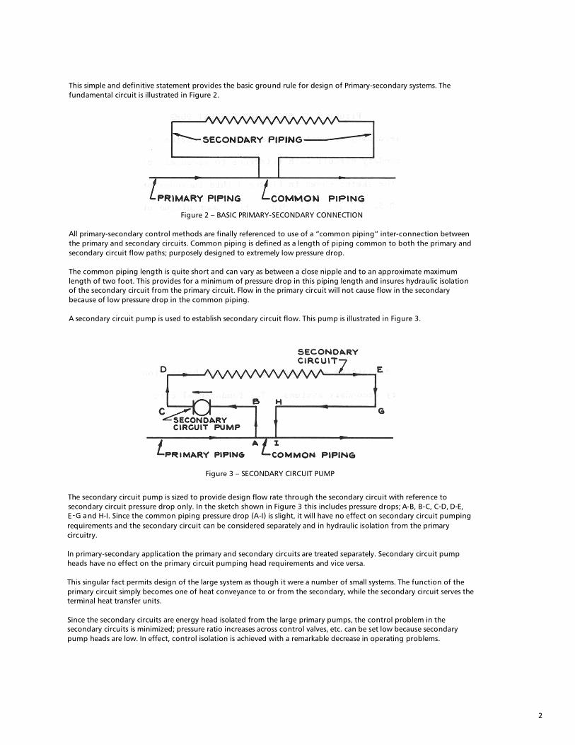
This simple and definitive statement provides the basic ground rule for design of Primary-secondary systems. The
fundamental circuit is illustrated in Figure 2.
Figure 2 – BASIC PRIMARY-SECONDARY CONNECTION
All primary-secondary control methods are finally referenced to use of a “common piping” inter-connection between the primary and secondary circuits. Common piping is defined as a length of piping common to both the primary and secondary circuit flow paths; purposely designed to extremely low pressure drop.
The common piping length is quite short and can vary as between a close nipple and to an approximate maximum length of two foot. This provides for a minimum of pressure drop in this piping length and insures hydraulic isolation of the secondary circuit from the primary circuit. Flow in the primary circuit will not cause flow in the secondary because of low pressure drop in the common piping.
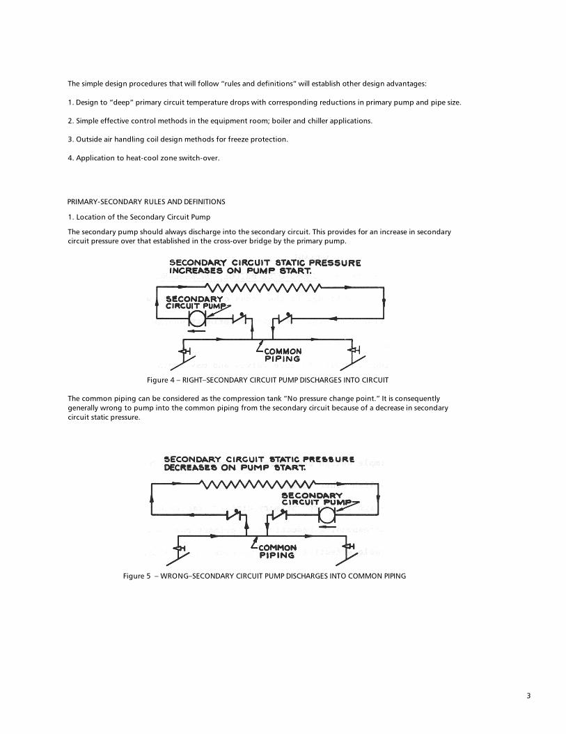
A secondary circuit pump is used to establish secondary circuit flow. This pump is illustrated in Figure 3.
Figure 3 – SECONDARY CIRCUIT PUMP
The secondary circuit pump is sized to provide design flow rate through the secondary circuit with reference to secondary circuit pressure drop only. In the sketch shown in Figure 3 this includes pressure drops; A-B, B-C, C-D, D-E, E-G and H-I. Since the common piping pressure drop (A-I) is slight, it will have no effect on secondary circuit pumping requirements and the secondary circuit can be considered separately and in hydraulic isolation from the primary circuitry.
In primary-secondary application the primary and secondary circuits are treated separately. Secondary circuit pump heads have no effect on the primary circuit pumping head requirements and vice versa.
This singular fact permits design of the large system as though it were a number of small systems. The function of the primary circuit simply becomes one of heat conveyance to or from the secondary, while the secondary circuit serves the terminal heat transfer units.
Since the secondary circuits are energy head isolated from the large primary pumps, the control problem in the secondary circuits is minimized; pressure ratio increases across control valves, etc. can be set low because secondary pump heads are low. In effect, control isolation is achieved with a remarkable decrease in operating problems.
3
The simple design procedures that will follow “rules and definitions” will establish other design advantages:
1. Design to “deep” primary circuit temperature drops with corresponding reductions in primary pump and pipe size.
2. Simple effective control methods in the equipment room; boiler and chiller applications.
3. Outside air handling coil design methods for freeze protection.
4. Application to heat-cool zone switch-over.
PRIMARY-SECONDARY RULES AND DEFINITIONS
1. Location of the Secondary Circuit Pump
The secondary pump should always discharge into the secondary circuit. This provides for an increase in secondary circuit pressure over that established in the cross-over bridge by the primary pump.
Figure 4 – RIGHT–SECONDARY CIRCUIT PUMP DISCHARGES INTO CIRCUIT
The common piping can be considered as the compression tank “No pressure change point.” It is consequently generally wrong to pump into the common piping from the secondary circuit because of a decrease in secondary circuit static pressure.
Figure 5 – WRONG–SECONDARY CIRCUIT PUMP DISCHARGES INTO COMMON PIPING

4
2. The Cross-over Bridge
Figure 6 – CROSS-OVER BRIDGE; UNDERSLUNG
The cross-over bridge is the cross connection between the primary supply main and primary return. It provides primary design flow rate to the common piping. The bridge contains balance valves and may contain a flow indicator. It is quite often underslung to simplify the initial air venting problem.
3. Cross-over Bridge; Overhead While the underslung bridge is generally preferred; overhead cross-over bridges are also employed:
Figure 7 – CROSS-OVER BRIDGE OVERHEAD
The overhead cross-over bridge cannot become “air bound” and will continuously “air purge” providing the piping pressure drop from the primary supply main to the primary return main (Δ P in Figure 7, expressed in feet of water) is greater than height “H” in Figure 7. This is the usual case. Should height “H" become greater than the estimated Δ P; or when downfed secondary circuits are used from an overhead cross-over, a manual air vent should be employed as illustrated in Figure 8.
Figure 8 – CROSS-OVER BRIDGE WITH MANUAL VENT
Overhead cross-over bridges should be designed to a minimum velocity on the order of 2’/sec. in order to drive any accumulated air down the cross-over return and into the primary return main.

5
4. Cross-over Bridle Length
Figure 9 – CROSS-OVER BRIDGE PIPING LENGTH
The cross-over bridge can be as long as necessary for inter-connection between the primary and the secondary circuits.
5. Cross-over Bridge Pipe Sizing The cross-over bridge is generally pipe sized to a piping friction loss rate ranging from 100 M”/ft. (approx. 1 ft. per 100 ft.) to 500 M”/ft. (approx. 4’ per 100’) and to the required primary flow rate. When required primary flow rate is equal to secondary flow, the cross-over bridge, common piping and secondary pipe sizes are equal as illustrated in Figure 10.
Figure 10 – CROSS-OVER PIPE SIZING – EQUAL PRIMARY AND SECONDARY FLOW RATES
Quite often, the primary flow rate will be considerably less than secondary flow. When the common piping is a part of the cross-over piping, special application procedure should be followed to prevent any possibility of “jet flow” through the common piping.
This is generally accomplished by sizing the common piping to secondary circuit pipe size and extending this pipe size in the cross-over bridge at least 8 pipe diameters upstream and approximately 4 pipe diameters downstream; as shown in Figure 11.
Figure 11 – CROSS-OVER BRIDGE PIPE SIZING: UNEQUAL P-S FLO:
6
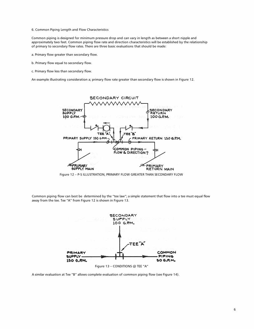
6. Common Piping Length and Flow Characteristics Common piping is designed for minimum pressure drop and can vary in length as between a short nipple and approximately two feet. Common piping flow rate and direction characteristics will be established by the relationship of primary to secondary flow rates. There are three basic evaluations that should be made: a. Primary flow greater than secondary flow. b. Primary flow equal to secondary flow. c. Primary flow less than secondary flow. An example illustrating consideration a; primary flow rate greater than secondary flow is shown in Figure 12.
Figure 12 – P-S ILLUSTRATION, PRIMARY FLOW GREATER THAN SECONDARY FLOW
Common piping flow can best be determined by the “tee law”; a simple statement that flow into a tee must equal flow away from the tee. Tee “A” from Figure 12 is shown in Figure 13.
Figure 13 – CONDITIONS @ TEE “A”
A similar evaluation at Tee “B” allows complete evaluation of common piping flow (see Figure 14).

7
Figure 14 – COMMON PIPING FLOW RATE AND DIRECTION PRIMARY FLOW GREATER THAN SECONDARY FLOW
It will be noted that secondary supply temperature must be equal to primary supply temperature so long as primary flow is only slightly greater than secondary flow. Most chilled water systems are designed with a constant supply water temperature requirement; primary supply water flow rate is consequently set at a slightly higher value than the secondary. This insures a continuous slight common piping bypass and establishes that secondary supply temperature is set by primary supply temperature. Should the secondary circuit pump be stopped the common piping flow rate would immediately increase to 150 GPM and the entire primary flow would bypass the secondary circuit. Consideration b; Primary cross-over flow equals secondary. The second consideration is for the case where primary flow equals secondary flow. The same circuit is used as previously except that the primary cross-over flow rate is decreased to 100 GPM. An evaluation at tee “A” is shown in Figure 15.
Figure 15 – TEE “A” FLOW; PRIMARY FLOW = SECONDARY FLOW
The over-all circuit can be shown as illustrated in Figure 16.
Figure 16 – COMPLETE CIRCUIT FLOW; PRIMARY FLOW = SECONDARY FLOW
When the primary flow rate is set equal to the secondary there will be no flow rate in the common piping. Secondary supply temperature will again be equal to primary supply and secondary return will equal primary return temperature. Consideration c; primary cross-over flow less than secondary.

8
The third evaluation is for the condition where the primary flow rate is less thin the secondary. The same circuit is used as previously except that primary cross-over flow is decreased to 50 GPM, while the secondary is maintained at 100 GPM.
The evaluation at tee “A” is shown in Figure 17.
50 GPM (Primary In) + 50 GPM (Common In) = 100 GPM (Secondary out)
Figure 17 – TEE “A” CONDITIONS, PRIMARY FLOW LESS THAN SECONDARY FLOW
The over-all circuit can be shown as illustrated in Figure 18.
Figure 18 – COMPLETE CIRCUIT FLOW; PRIMARY FLOW LESS THAN SECONDARY FLOW
The most important characteristic of system design where secondary circuit flow rate is greater than primary is the mix occurring at tee “A”. Common piping flow, at a temperature equal to secondary circuit return mixes with primary supply water to provide a mixed secondary supply temperature. This most important characteristic provides smooth reset controllability, establishes “deep” primary circuit temperature drop possibilities and can be used to great advantage in the numerous P-S control arrangements made possible. A second important conclusion that can be drawn from Figure 1 is that primary cross-over return temperature must be equal to secondary return. In general P-S design establishes that the primary cross-over bridge flow rate will be equal to or less than secondary flow. This means that primary cross-over bridge return temperature for the full load design condition will always be equal to secondary return. Common Piping Flow Characteristics Generalized Control Applications. The “tee law”; that flow into a tee must equal the flow that leaves, can be used for assessing common piping flow characteristics for the variety of P-S control possibilities.
9
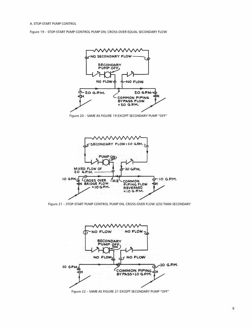
A. STOP-START PUMP CONTROL Figure 19 – STOP-START PUMP CONTROL PUMP ON; CROSS-OVER EQUAL SECONDARY FLOW
Figure 20 – SAME AS FIGURE 19 EXCEPT SECONDARY PUMP “OFF”
Figure 21 – STOP-START PUMP CONTROL PUMP ON, CROSS-OVER FLOW LESS THAN SECONDARY
Figure 22 – SAME AS FIGURE 21 EXCEPT SECONDARY PUMP “OFF”
10
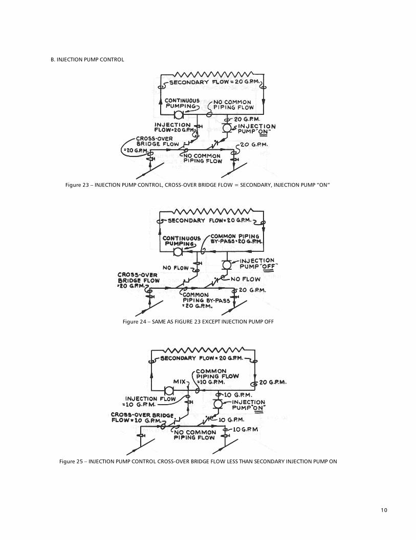
B. INJECTION PUMP CONTROL
Figure 23 – INJECTION PUMP CONTROL, CROSS-OVER BRIDGE FLOW = SECONDARY, INJECTION PUMP “ON”
Figure 24 – SAME AS FIGURE 23 EXCEPT INJECTION PUMP OFF
Figure 25 – INJECTION PUMP CONTROL CROSS-OVER BRIDGE FLOW LESS THAN SECONDARY INJECTION PUMP ON
11
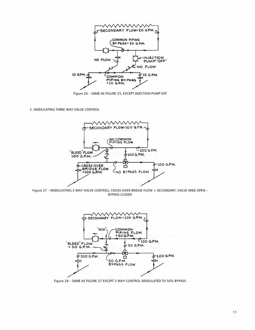
Figure 26 – SAME AS FIGURE 25, EXCEPT INJECTION PUMP OFF
C. MODULATING THREE WAY VALVE CONTROL
Figure 27 – MODULATING 3 WAY VALVE CONTROL; CROSS-OVER BRIDGE FLOW = SECONDARY; VALVE WIDE OPEN –
BYPASS CLOSED
Figure 28 – SAME AS FIGURE 27 EXCEPT 3 WAY CONTROL MODULATED TO 50% BYPASS

12
Figure 29 – MODULATING 3 WAY VALVE CONTROL; CROSS-OVER FLOW LESS THAN SECONDARY; VALVE WIDE OPEN –
BYPASS CLOSED
Figure 30 – SAME AS FIGURE 28 EXCEPT 3 WAY CONTROL MODULATED TO 50% BYPASS
D. MODULATING TWO WAY VALVE CONTROL
Figure 31 – TWO WAY MODULATING VALVE CONTROL; APPLY ONLY WHEN CROSS OVER FLOW IS LESS THAN 30% IF
SECONDARY; VALVE WIDE OPEN

13
Figure 32 – SAME AS FIGURE 31 EXCEPT VALVE PARTIALLY CLOSED
Figure 33 – SAME AS FIGURE 31 EXCEPT VALVE CLOSED
8. Cross-over Bridle to Secondary Circuit Flow Relationships. Each secondary circuit is served by a cross-over bridge which supplies necessary primary water. Required cross-over flows are established by secondary circuit heating or cooling needs. There are two conditions that must be evaluated: 1. Secondary circuit temperature equal to primary temperature. 2. Secondary circuit design temperature different from primary temperature.
14
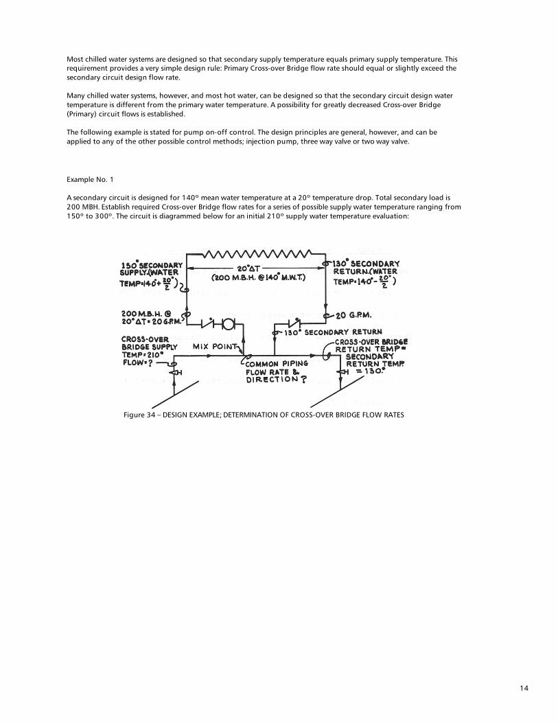
Most chilled water systems are designed so that secondary supply temperature equals primary supply temperature. This requirement provides a very simple design rule: Primary Cross-over Bridge flow rate should equal or slightly exceed the secondary circuit design flow rate. Many chilled water systems, however, and most hot water, can be designed so that the secondary circuit design water temperature is different from the primary water temperature. A possibility for greatly decreased Cross-over Bridge (Primary) circuit flows is established. The following example is stated for pump on-off control. The design principles are general, however, and can be applied to any of the other possible control methods; injection pump, three way valve or two way valve.
Example No. 1 A secondary circuit is designed for 140º mean water temperature at a 20º temperature drop. Total secondary load is 200 MBH. Establish required Cross-over Bridge flow rates for a series of possible supply water temperature ranging from 150º to 300º. The circuit is diagrammed below for an initial 210º supply water temperature evaluation:
Figure 34 – DESIGN EXAMPLE; DETERMINATION OF CROSS-OVER BRIDGE FLOW RATES

15
Step #1: Determine Cross-over Bridge Temperature Drop. (a) Cross-over Bridge return water temperature will equal secondary return water temperature; in this case 130º F. (b) Assuming Primary cross-over Bridge Supply Temperature = 210º, the cross-over bridge temperature drop will be: 210º - 130º = 80º Δ T.
Step #2: Determine Cross-over Bridge Flow Rate. At 200 MBH load the required cross-over bridge flow rate will be: 200,000 BTU/hr = 5 GPM 80º Δ T x 500 This value can be easily established by use of the B&G '“system Syzer.” Step #3 : Determine common piping flow rate and direction. The common piping flow rate will be secondary circuit flow minus cross-over flow: In this case: 20 GPM minus 5 = 15 GPM Common piping flow (reversed to mix point) Conditions for the example problem can be diagrammed as below:
Figure 35 – DESIGN EXAMPLE FLOW RATES

16
In order to illustrate the general nature of cross-over flow determination a modulating three way valve application flow diagram is shown for full load conditions and for the conditions established in Example 1.
Figure 36 – DESIGN EXAMPLE FLOW RATES – 3 WAY VALVE APPLICATION
The 150º supply temperature as a “mixed” temperature result of 5 GPM @ 210º plus 15 GPM @ 130º can be verified by a heat balance: 15 GPM X 130º + 5 GPM X 210º = 20 GPM X 150º 1950 + 1050 = 3000 3000 = 3000 (heat balance satisfied) Required primary cross-over flow rates are illustrated in Table 1 for a variety of primary supply temperatures; maintaining the other example conditions:
TABLE 1
* Primary Cross-over Bridge Return Temp. will always equal secondary circuit return at full load (see page 14).

17
The example illustrates one of the outstanding advantages of primary-secondary pumping; that the primary circuit can be designed for very high temperature drops so that both primary pumping and pipe costs can be reduced. It should be emphasized that the primary circuit serves only a heat conveyance function and that its temperature drop or rise can be entirely different from the secondary circuit it serves. 9. Stop-start Pump Control of Secondary Circuit This control application is a simple adaption of a control method proven in several million residential systems. It has been widely used in commercial control.
Figure 37 – START-STOP PUMP CONTROL FOR SPACE TEMPERATURE CONTROL
The only real difference between the residential system and its Primary-secondary adoption is that the heat source is the common piping rather than a boiler. The secondary circuits are generally quite short; usually limited to about 200’ maximum. This is because of the time relationship between heating of the “near,” as opposed to the “far” radiation. It is necessary that water flow from the primary to the secondary be absolutely prevented during the pump off-thermostat satisfied condition.
Flo Control valves prevent hot water flow as caused by gravity heads, or by the slight pressure drop established across the common piping when the secondary pump is off.

18
9. Flo Control Valve Need; Stop-start Pump Control Flo Control Valves are weighted check valves and are used to block flow as induced by slight common piping pressure drop or by gravity heads. They are generally needed whenever pumps are used for control. The Flo Control Valve is statically weighted to approximately .6 ft. of water head. It is in automatic check and anti-gravity flow operation when the stem is turned down. The valve is open and will not perform its anti-gravity flow function when the stem is turned up (see Figure 38).
Figure 38 – FLO CONTROL STEM MUST BE DOWN
10. Need for two Flo Control Valves Start-Stop Pump Control
Two Flo Control valves are generally illustrated for application with start-stop pump control of secondary circuits. This is because gravity flow can occur within a single pipe as shown in Figure 39.
Figure 39 – GRAVITY FLOW - SINGLE PIPE
During the 1920‘s a great many one pipe gravity systems were installed, attesting to the control problems that could occur because of the introduction of “Gravity” hot water into secondary circuit radiation located close to the secondary circuit return riser.

19
A single Flo Control Valve can be used when the secondary circuit return riser is underslung as in Figure 40.
Figure 40 – SINGLE FLO CONTROL VALVE APPLICATION STOP-START PUMP CONTROL
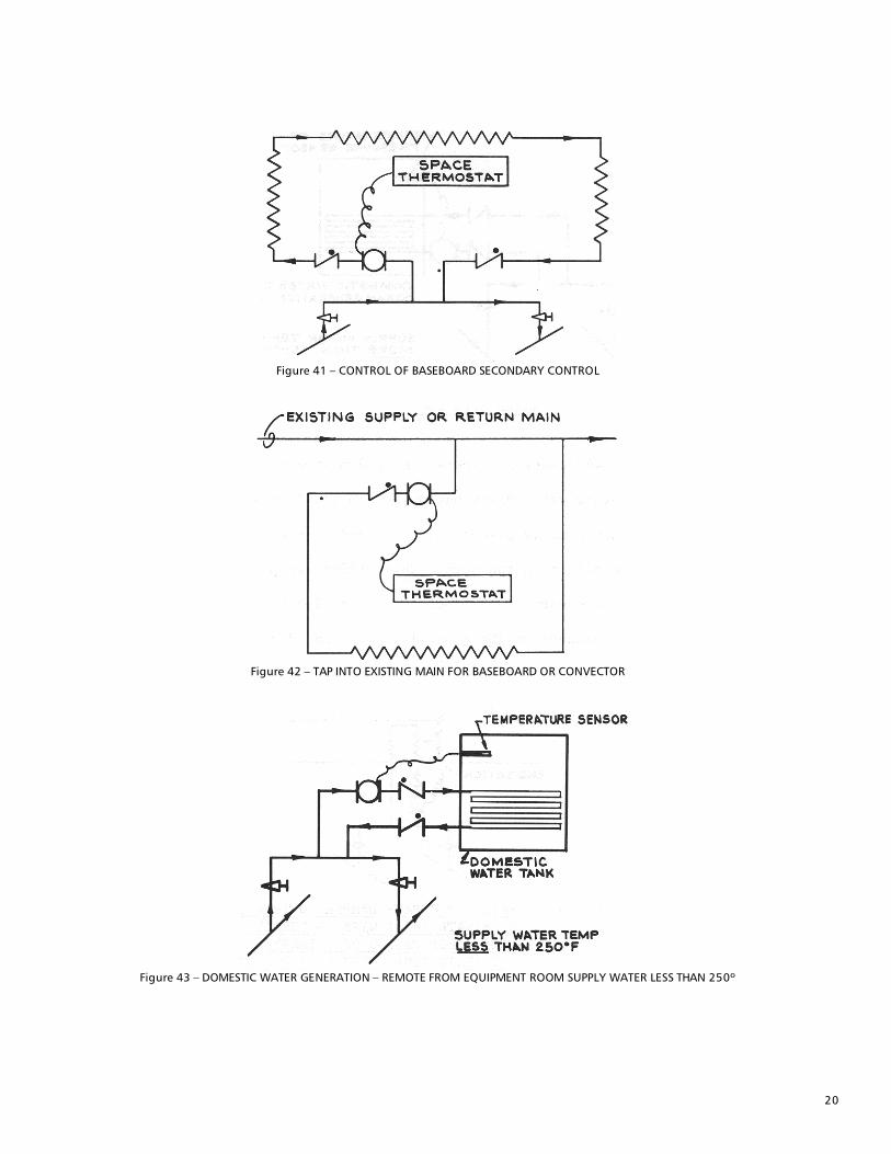
11. Single Pump Control Applications Start-stop operation of the secondary pump has been used for control in a variety of applications . Some of these are described below:
20
Figure 41 – CONTROL OF BASEBOARD SECONDARY CONTROL
Figure 42 – TAP INTO EXISTING MAIN FOR BASEBOARD OR CONVECTOR
Figure 43 – DOMESTIC WATER GENERATION – REMOTE FROM EQUIPMENT ROOM SUPPLY WATER LESS THAN 250º
21
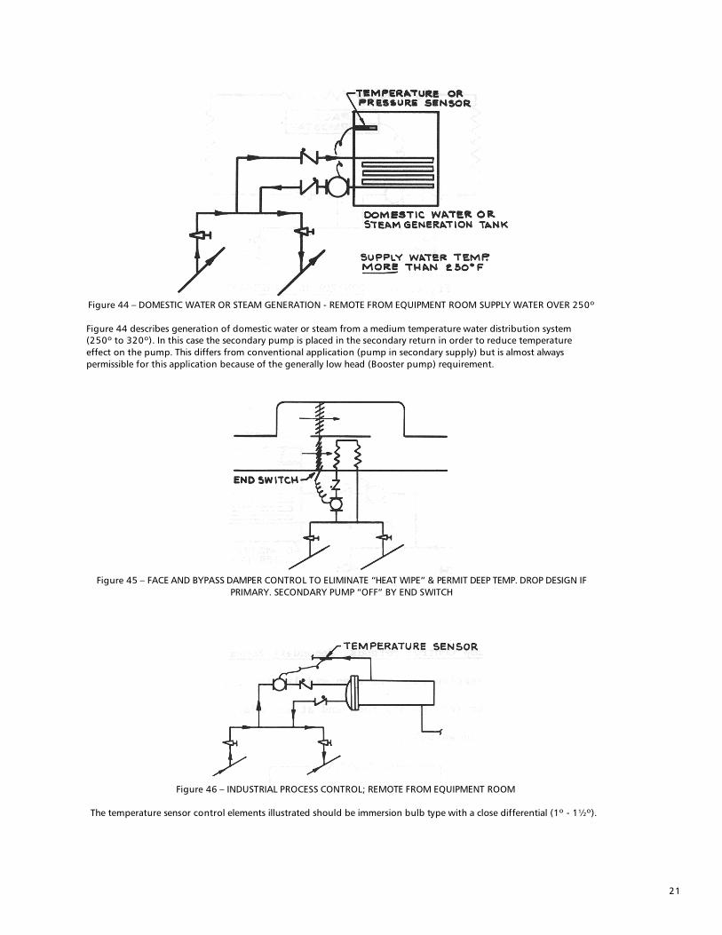
Figure 44 – DOMESTIC WATER OR STEAM GENERATION - REMOTE FROM EQUIPMENT ROOM SUPPLY WATER OVER 250º Figure 44 describes generation of domestic water or steam from a medium temperature water distribution system (250º to 320º). In this case the secondary pump is placed in the secondary return in order to reduce temperature effect on the pump. This differs from conventional application (pump in secondary supply) but is almost always permissible for this application because of the generally low head (Booster pump) requirement.
Figure 45 – FACE AND BYPASS DAMPER CONTROL TO ELIMINATE “HEAT WIPE” & PERMIT DEEP TEMP. DROP DESIGN IF
PRIMARY. SECONDARY PUMP “OFF” BY END SWITCH
Figure 46 – INDUSTRIAL PROCESS CONTROL; REMOTE FROM EQUIPMENT ROOM
The temperature sensor control elements illustrated should be immersion bulb type with a close differential (1º - 1½º).

22
12. Constant Secondary Pump Operation - Terminal Unit Control Only Secondary zone pumping is often used in large systems employing high head distribution pumps in order to eliminate “shut off head” control valve problems.
Figure 47 – SECONDARY ZONE PUMPING; ELIMINATION OF PRIMARY HEAD EFFECT ON TERMINAL UNIT CONTROL
Since the secondary zone pump is in continuous operation, Flo Control Valves are not needed.
23
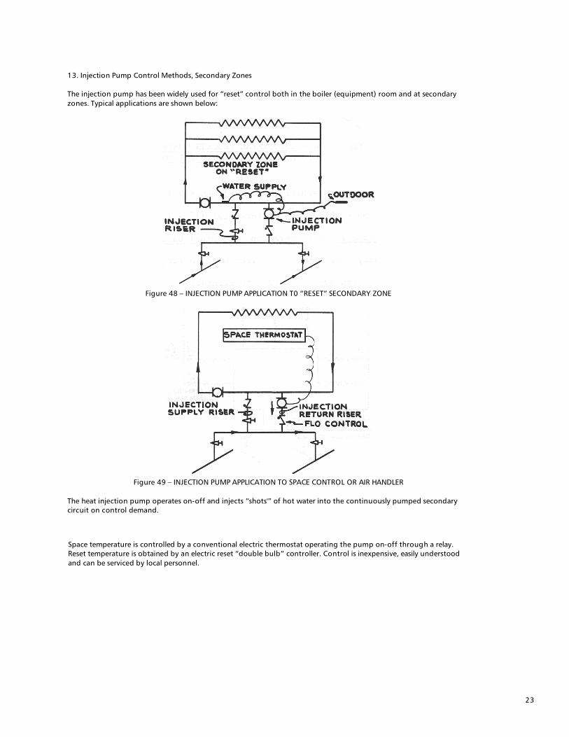
13. Injection Pump Control Methods, Secondary Zones The injection pump has been widely used for “reset” control both in the boiler (equipment) room and at secondary zones. Typical applications are shown below:
Figure 48 – INJECTION PUMP APPLICATION T0 “RESET” SECONDARY ZONE
Figure 49 – INJECTION PUMP APPLICATION TO SPACE CONTROL OR AIR HANDLER
The heat injection pump operates on-off and injects “shots'” of hot water into the continuously pumped secondary circuit on control demand.
Space temperature is controlled by a conventional electric thermostat operating the pump on-off through a relay. Reset temperature is obtained by an electric reset “double bulb” controller. Control is inexpensive, easily understood and can be serviced by local personnel.

24
14. Injection Riser and Injection Pump Sizing The injection riser is sized to the full load primary cross-over flow requirement and, in most cases, is equal in size to the cross-over pipe size. The injection pump is always sized to the full load primary cross-over flow requirement. This is illustrated in Figure 50 for primary flow equal to Secondary Flow and in Figure 51 for primary Cross-over flow less than secondary.
Figure 50 – INJECTION SIZING; CROSS-OVER FLOW EQUAL TO SECONDARY FLOW
Figure 51 – INJECTION SIZING; CROSS-OVER FLOW LESS THAN SECONDARY FLOW
15. Need for Injection Line Flo Control Valve Slight pressure drop, caused by continuous flow through the common piping located in both the cross-over and secondary circuits will cause a flow from the primary into the secondary - with consequent lack of low load controlability. Flow control valves will prevent injection line flow - except under control demand. 16. Injection Pump Selection and Operational Considerations The injection pump will, almost always, be a small inexpensive booster pump and can be selected and operated without fear of overload. The pump should be selected, however, so that at least a 4’ to 5’ restrictive head is placed against it by the injection riser, the Flo Controls and the injection line riser balance valve. Time operation of the injection pump will be dictated by the differential precision of its controlling device and the rate of injected flow. The injection pump should operate for at least 30 seconds per time cycle to allow its motor to change from “start” to “operating” windings. The on-off control differential should be set to as narrow a band as possible and the minimum time cycle set by adjustment of the balance valve.

25
17. Injection Pump Applications The Injection Pump is finding increased use in both Industrial and Commercial application. Some generalized applications are shown below:
Figure 52 – RESET CONTROL SECONDARY ZONE
Figure 53 – REHEAT OR SPACE TEMP CONTROL - AIR HANDLING UNIT
Figure 54 – CIRCULATED DOMESTIC WATER STORAGE TANK

26
Figure 55 – INSTANTANEOUS DOMESTIC WATER CONTROLLED FROM SHELL SIDE
Figure 56 – INDUSTRIAL FLUID TEMP. CONTROL (PUMP CAPACITIES EQUAL MAX. FLUID DRAW RATE)
Figure 57 – SIMPLIFIED CHANGE-OVER PLUS HOT WATER RESET FOR HEAT-COOL SYSTEM
A simplified change-over described in Figure 57 eliminates a great many operating change-over problems. The system pump operates continuously, and the change-over from heating to cooling, or vice versa, is effected by a simple two position switch which either energizes the boiler circuit or the chiller circuit. Boiler side activation starts the boiler and its injection pump. The injection pump controls system water temperatures to reset requirements. Chiller side activation starts the chiller and its pump when the over-riding aquastat determines that system water temperature are low enough (85º neighborhood) to permit introduction into the chiller. The change-over system described in Figure 57 has been applied with great success with cast iron boilers and with smaller steel boilers (less than 250 MBH gross). Application to large fire tube steel boilers should be referenced to the boiler manufacturer for his consideration taking into account the possibility of boiler “shock.” Reference to non-shock application is made in Figure 69, page 43 of this discussion.

27
18. Modulating Three Way Valve Control Application to Primary-Secondary; Preliminary Discussion Modulating three way valves are used in three different basic arrangements for Primary-Secondary application.
Figure 58 – MIXING VALVE APPLICATION IN SECONDARY CIRCUIT
Figure 59 – BYPASS OR DIVERTING VALVE IN SECONDARY
The bypass or diverting valve application, Figure 59, is preferred to the mixing application since it solves the secondary circuit pressure drop problem; the secondary pump does not have a restrictive suction pressure drop and the Flo Control Valve “swing” is such that secondary pressure can never be less than primary. Sizing of the three way valve to the “controlling flow” will still be a problem when required primary input flow rate is less than secondary. The arrangement shown in Figure 60 overcomes the problems noted above and is highly recommended. The arrangement has these advantages: 1. The control valve is sized to the cross-over bridge flow rate, which is always the controlling flow rate. 2. The particular location of the three way requires an “underslung” bleed riser if the operator is to be placed at the top of the valve. The underslung bleed riser provides a thermal anti-gravity flow leg which eliminates the need for the Flo Control Valve (an adaptation requiring the F1l Control is shown in Figure 61). 3. Pressure at the secondary circuit pump can never be less than primary circuit pressure as developed in the cross-over bridge. 4. Cross-over bridge can be balanced by proper selection (Cv rating) of the three way valve. It will be noted that the common piping has been moved from its conventional location in the cross-over bridge to a new location in the secondary circuit.

28
Figure 60 – MIXING VALVE IN CROSS-OVER PIPING – UNDERSLUNG RISERS
Figure 61 – MIXING VALVE IN CROSS-OVER PIPING – OVERHEAD
For these applications, the secondary zone pump is in continuous operation. Secondary water temperature is modulated up or down depending on the amount of primary water the three way valve admits into the secondary through the “bleed riser” and to the mix point. Control of the secondary circuit is thus vested in water temperature change – rather than the “flow change” control established by bypass control methods. The continuous flow established by P-S arrangements has important advantages where secondary zones are to be separately reset and is most especially advantageous for freeze protection of air handling coils.
The application illustrated in Figure 58 has been in common usage for some time and despite some serious disadvantages has performed remarkably well. The disadvantages are: 1. The three way valve is interposed as a pressure drop directly at the secondary pump suction. Should valve pressure drop be high, the secondary pump can go into cavitation with resultant pump damage and reduced flow rate. 2. The Flo Control valve is intended to stop “one pipe” internal gravity flow from the primary to the secondary circuit when the three way is closed to the “bleed riser” (no load demand). While the valve will do this, it introduces other problems:
When the three way is closed to the bleed riser (primary) the Flo Control will act as a check against entry of any water from the primary and into the secondary. A decrease in secondary circuit water temperature will then cause contraction and a rapid reduction in secondary pressure. The reduction in secondary pressure can again cause cavitation. 3. The three way valve is generally “line sized” to the secondary flow rate. Should the full load flow requirement from the primary be less than secondary flow, the valve is oversized. The valve will not be sized to the flow it is trying to control (cross-over or bleed riser flow). Under these circumstances the three way valve is oversized and will have a limited control “stroke.”

29
19. Pipe and valve Sizing for Three Way Modulating Valve Application to Primary-secondary Pumping. The bleed risers are sized to the full load primary cross-over flow requirement and is equal in size to the cross-over pipe size. The control valve is sized to the cross-over flow requirement and to some stated P.D. It would be usual to assign approximately 10’ P.D. to this valve unless balance requirements dictate otherwise (see Hydronic System Flow Balance Manual). Sizing examples are illustrated for cross-over flow equal to secondary and for cross-over flow less than secondary.
Figure 62 – MODULATING THREE WAY PIPE SIZING: CROSSOVER FLOW = SECONDARY
Figure 63 – MODULATING THREE WAY; CROSS-OVER FLOW LESS THAN SECONDARY

30
20. Modulating Three Way Control Application to Primary Secondary; Applications Illustrations Pumps and valves together can perform control functions which valves alone or pumps alone cannot perform. In a closed loop hydronic circuit, mixing of two different temperature waters can only take place through action of a pump. The modulating control valve provides a “controlled modulation rate” of the mixed water which can be closely approached by the rapid “snap” on-off action of the injection pump. True mixed water temperature modulation can only be achieved by the modulating control valve pump combination, however. Some application examples follow:
Figure 64 – INDOOR-OUTDOOR RESET OF SECONDARY
Figure 65 – SPACE TEMPERATURE CONTROL OF SECONDARY
Figure 66 – AIR HANDLER-FREEZE PROTECTION PLUS AIR TEMP. CONTROL

31
Figure 67 – CIRCULATED DOMESTIC WATER STORAGE TANK
Figure 68 – INDUSTRIAL FLUID TEMP CONTROL
Figure 69 – SIMPLE CHANGE-OVER, RESET OF HOT WATER, BOILER SHOCK PROTECTION, CHILLER USED TO COOL DOWN
“HOT” SYSTEM ON CHANGE-OVER CHILLER STEP CONTROL NOT EFFECTED BY CHANGES IN SYSTEM FLOW RATE.
In this illustration, the change-over is accomplished by a simple two position switch; activating either the chiller or boiler circuits. For heating, the boiler pump flows the boiler continuously at an established flow rate. The three way valve resets system water as required – except when overridden by a high temperature difference signal between boiler supply and return as might occur after a shut down (cold system) or on a change-over (cooling to heating) and with the boiler up to temperature. The arrangement shown will “bleed” system water into the boiler circuit at a controlled rate until full reset temperature is reached.
32
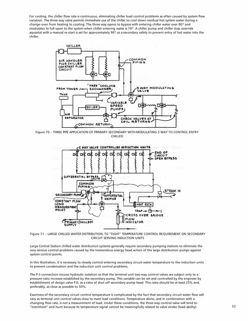
For cooling, the chiller flow rate is continuous, eliminating chiller load control problems as often caused by system flow variation. The three way valve permits immediate use of the chiller to cool down residual hot system water during a change-over from heating to cooling. The three way opens to bypass with entering chiller water over 80º and modulates to full open to the system when chiller entering water is 70º. A chiller pump and chiller stop override aquastat with a manual re-start is set for approximately 90º as a secondary safety to prevent entry of hot water into the chiller.
Figure 70 – THREE PIPE APPLICATION OF PRIMARY-SECONDARY WITH MODULATING 3 WAY TO CONTROL ENTRY
CHILLED
Figure 71 – LARGE CHILLED WATER DISTRIBUTION; TO “TIGHT” TEMPERATURE CONTROL REQUIREMENT ON SECONDARY
CIRCUIT SERVING INDUCTION UNITS Large Central Station chilled water distribution systems generally require secondary pumping stations to eliminate the very serious control problems caused by the tremendous energy head action of the large distribution pumps against system control points. In this illustration, it is necessary to closely control entering secondary circuit water temperature to the induction units to prevent condensation and the induction unit control problems. The P-S connection insures hydraulic isolation so that the terminal unit two way control valves are subject only to a pressure ratio increase established by the secondary pump. This variable can be set and controlled by the engineer by establishment of design valve P.D. as a ratio of shut-off secondary pump head. This ratio should be at least 25% and, preferably, as close as possible to 50%. Exactness of the secondary circuit control temperature is complicated by the fact that secondary circuit water flow will vary as terminal unit control valves close to meet load conditions. Temperature alone, and in combination with a changing flow rate, is not a measurement of load. Under these conditions, the three way control valve will tend to “overshoot” and hunt because its temperature signal cannot be meaningfully related to valve stroke (load ability).
33
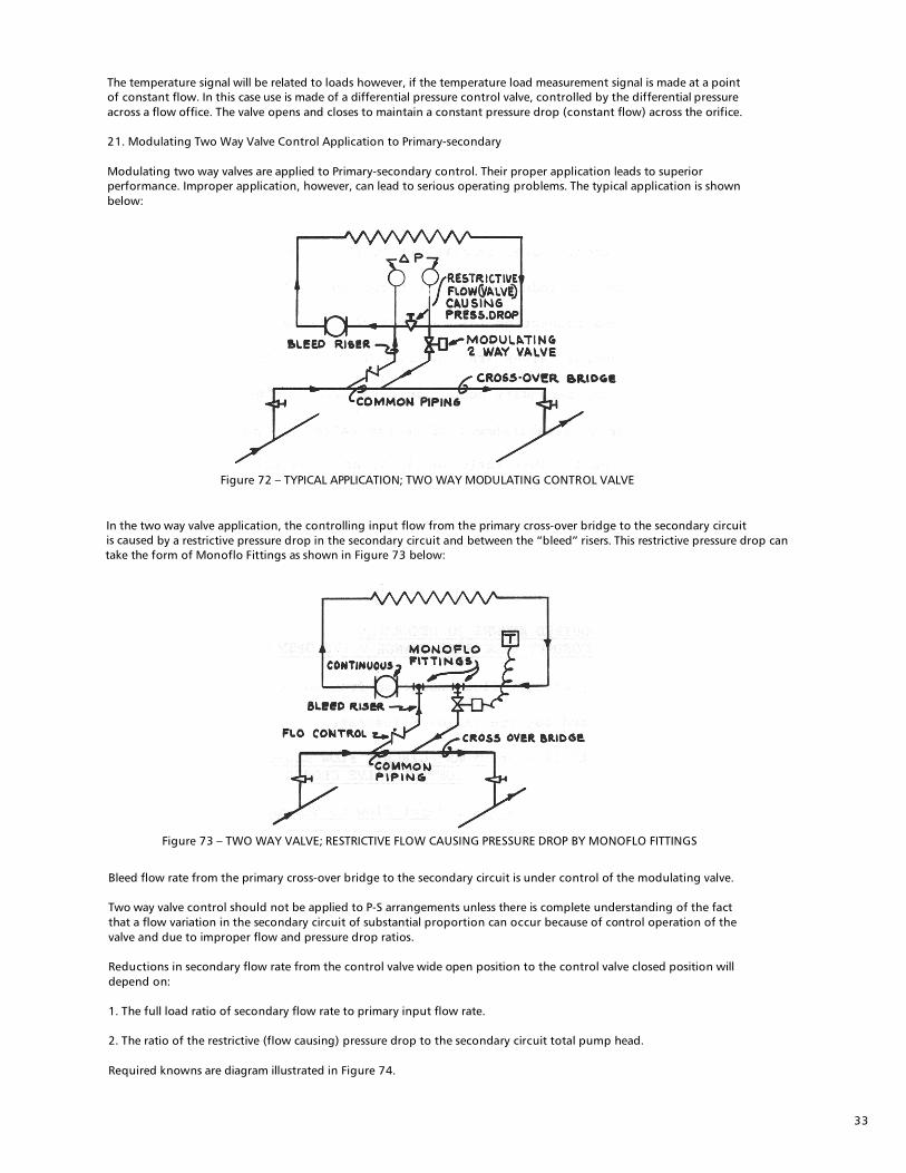
The temperature signal will be related to loads however, if the temperature load measurement signal is made at a point of constant flow. In this case use is made of a differential pressure control valve, controlled by the differential pressure across a flow office. The valve opens and closes to maintain a constant pressure drop (constant flow) across the orifice. 21. Modulating Two Way Valve Control Application to Primary-secondary Modulating two way valves are applied to Primary-secondary control. Their proper application leads to superior performance. Improper application, however, can lead to serious operating problems. The typical application is shown below:
Figure 72 – TYPICAL APPLICATION; TWO WAY MODULATING CONTROL VALVE
In the two way valve application, the controlling input flow from the primary cross-over bridge to the secondary circuit is caused
by a restrictive pressure drop in the secondary circuit and between the “bleed” risers. This restrictive pressure drop can
take the form of Monoflo Fittings as shown in Figure 73 below:
Figure 73 – TWO WAY VALVE; RESTRICTIVE FLOW CAUSING PRESSURE DROP BY MONOFLO FITTINGS
Bleed flow rate from the primary cross-over bridge to the secondary circuit is under control of the modulating valve. Two way valve control should not be applied to P-S arrangements unless there is complete understanding of the fact that a flow variation in the secondary circuit of substantial proportion can occur because of control operation of the valve and due to improper flow and pressure drop ratios. Reductions in secondary flow rate from the control valve wide open position to the control valve closed position will depend on: 1. The full load ratio of secondary flow rate to primary input flow rate. 2. The ratio of the restrictive (flow causing) pressure drop to the secondary circuit total pump head. Required knowns are diagram illustrated in Figure 74.
34
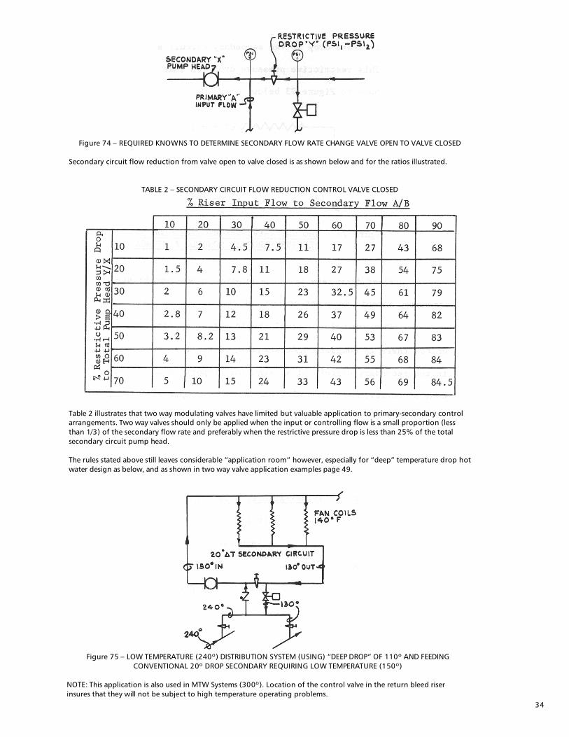
Figure 74 – REQUIRED KNOWNS TO DETERMINE SECONDARY FLOW RATE CHANGE VALVE OPEN TO VALVE CLOSED
Secondary circuit flow reduction from valve open to valve closed is as shown below and for the ratios illustrated.
TABLE 2 – SECONDARY CIRCUIT FLOW REDUCTION CONTROL VALVE CLOSED
Table 2 illustrates that two way modulating valves have limited but valuable application to primary-secondary control arrangements. Two way valves should only be applied when the input or controlling flow is a small proportion (less than 1/3) of the secondary flow rate and preferably when the restrictive pressure drop is less than 25% of the total secondary circuit pump head. The rules stated above still leaves considerable “application room” however, especially for “deep” temperature drop hot water design as below, and as shown in two way valve application examples page 49.
Figure 75 – LOW TEMPERATURE (240º) DISTRIBUTION SYSTEM (USING) “DEEP DROP” OF 110º AND FEEDING
CONVENTIONAL 20º DROP SECONDARY REQUIRING LOW TEMPERATURE (150º) NOTE: This application is also used in MTW Systems (300º). Location of the control valve in the return bleed riser insures that they will not be subject to high temperature operating problems.
35
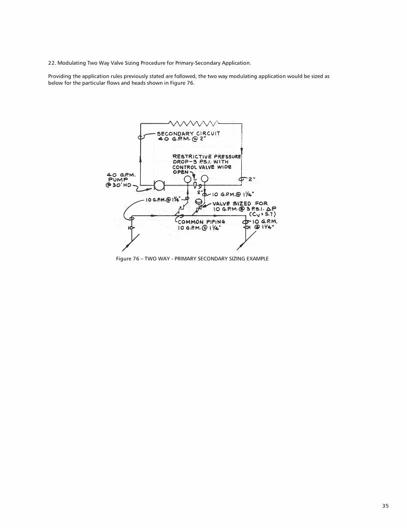
22. Modulating Two Way Valve Sizing Procedure for Primary-Secondary Application. Providing the application rules previously stated are followed, the two way modulating application would be sized as below for the particular flows and heads shown in Figure 76.
Figure 76 – TWO WAY - PRIMARY SECONDARY SIZING EXAMPLE

36
Modulating Two Way Valve--Primary Secondary Applications. Applications are generally limited to design involving considerable design temperature drop difference between the primary and secondary circuits. When the required conditions are established the two way valve should be used; it is generally considered a superior control instrument compared to the three way (especially for small flow control requirements) and is less expensive.
Figure 77 – 100º PRIMARY TEMP DROP VS. 20º SECONDARY DROP; 20% FLOW RATIO
Figure 78 – 100º PRIMARY TEMP DROP VS. 20º SECONDARY DROP; 20% FLOW RATIO

37
Figures 77 and 78 illustrate application to low temperature design (less than 250º). As noted in Figure 75, the same design principles are often used with medium temperature water (300º).
Figure 79 – TWO WAY MODULATING “RESET” CONTROL APPLIED TO HEATING SIDE OF HEAT-COOL SYSTEM WITH WILD
STEAM T0 WATER EXCHANGER Figure 79 is an adaptation of a wild flowing steam to water exchanger used by W. A. Goodman in High Rise Application to avoid high pressure hot water boiler problem. The exchanger is wild; no control valve, and is located over the boiler so as not to require traps, etc. The particular design circumstances are such that a relatively small two way valve could be used for reset during the heating season providing the exchanger is sized to yield approximately 200º leaving water. 24. Primary Circuit Design Basics The primary circuit is designed after an evaluation of each secondary circuit and its need for primary water flow through its cross-over bridge. The primary circuit is then designed, using conventional practice, to provide proper cross-over bridge flow rates. The primary main can be either two pipe reverse return, two pipe direct return, or simple one pipe. Design procedure for determination of cross-over bridge flow rates is followed as described under item 8, page 19. Briefly, the following step procedure will define cross-over bridge flow rates:
Step #1: Determine cross-over bridge Temp. Drop
(a) cross-over bridge return water temperature will equal Secondary Circuit return temp. (b) Subtract cross-over bridge return temp. from primary supply.
Step #2: Determine Cross-over bridge flow rate; this will be determined by secondary circuit load in MBH and cross over bridge ΔT. Example: A two pipe reverse return primary circuit is to serve four secondary circuits. Each secondary circuit is designed for 20º temperature drop. The following secondary circuit loads, flow rates, and supply-return temperatures will apply. Secondary Circuits; loads, flow rates and temp.
Secondary circuit return temperatures and loads will now be used for evaluation of cross-over bridge design temperature drops and required flow rates for a primary supply temp of 220ºF.
Δ T.

38
The two pipe reversed return primary circuit would then be pipe sized to the flow rates shown in Figure 80.
Figure 80 – REVERSE RETURN PRIMARY CIRCUIT FLOW RATES - DESIGN EXAMPLE
It will be noted that the overall load of 3,200 MBH will be carried by a primary flow rate of 86.8 GPM. The resulting over-all temperature drop will then be approximately 75º ΔT. Primary flow rates could be further reduced by an increase in primary supply water temperature. The procedure outlined above differs from conventional practice where distribution flow rates are stated to a fixed overall design temperature drop; usually 20º ΔT. The difference in primary distribution flow rates is large; 320 GPM for the fixed 20º ΔT design as against 86.8 GPM for the primary-secondary “separate evaluation” design method. The 75º resultant temperature drop compares favorably with many HTW (400º) designs. The two pipe reversed return example design could be controlled as illustrated:
Figure 81 – POSSIBLE SECONDARY CIRCUIT CONTROL ARRANGEMENTS - DESIGN EXAMPLE
The primary circuit two pipe direct return design is illustrated below for the cross-over bridge flow rates determined in the design example.

39
Figure 82 – DIRECT RETURN PRIMARY CIRCUIT FLOW RATES - DESIGN EXAMPLE
The two pipe direct return circuit will often be in hydraulic unbalance because of differing circuit lengths. The balance problem is often solved by either/or: 1. Use of flo indicators on cross-over bridge (see Figure 83). 2. Use of high pressure drop (15 to 25 ft.) three way valves in each cross-over bridge (see figure 84).
Figure 83 – FLO INDICATOR IN CROSS-OVER BRIDGE; DIRECT RETURN DESIGN
Figure 84 – HIGH P.D. 3 WAY IN EACH CROSS-OVER BRIDGE; DIRECT RETURN DESIGN
The one pipe primary circuit distribution main requires special design techniques. 25. One Pipe Primary Main Design The one pipe primary distribution main has unique advantages over the more conventional two pipe, because balance is automatically established by the design procedure and because of cost saving possibilities. The “one pipe” design is predicated (for either heating or cooling) on each secondary circuit having primary circuit water temperatures available at the secondary circuit supply which will meet secondary circuit requirements.

40
Example: A one pipe primary main will serve four secondary circuits. Each secondary is designed for 20º temperature drop. The following secondary circuit loads, flow rates and supply-return temperatures will apply:
Step #1: Determine one pipe main flow rate
The last circuit (#4) requires 190º supply temperature for secondary circuit design conditions. Given a 240º primary supply temperature, the primary circuit can be designed to a 50º ΔT for the load represented by the first three circuits (#1, #2, and #3). The load summation for the first three circuits will be 2,700 MBH (200 + 2,000 + 500). At a 50º ΔT, this load represents 110 GPM flow rate. The 110 GPM flow rate will provide 190º supply water for circuit #4 and represents a total one pipe circuit temperature drop (including circuit #4) of approximately 60º. The one pipe circuit, as proposed, can then be laid out:
Figure 85 – ONE PIPE PRIMARY FLOW RATE DETERMINATION FOR DESIGN EXAMPLE
Figure 89 – TOTAL CIRCUIT; INJECTION RISER FLOW RATES

41
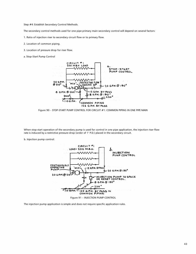
Step #4: Establish Secondary Control Methods. The secondary control methods used for one pipe primary main secondary control will depend on several factors: 1. Ratio of injection riser to secondary circuit flow or to primary flow. 2. Location of common piping. 3. Location of pressure drop for riser flow. a. Stop-Start Pump Control
Figure 90 – STOP-START PUMP CONTROL FOR CIRCUIT #1: COMMON PIPING IN ONE PIPE MAIN
Step #2: Determine available one pipe primary main supply temperature at each secondary circuit. The available primary circuit temperature will be established by a sequenced determination of primary water temperature drop as effected by secondary load in MPH. As an example, circuit #1 has a 200 MBH load. A primary flow rate at 110 GPM establishes a 3.6º (say 4º) primary temperature drop. Given a 240º entering primary temperature, the primary leaving temperature will be: 240 - 4 = 236º. As below:
Figure 86 – TEMPERATURE DROP SEQUENCE ONE PIPE PRIMARY MAIN

42
A complete temperature drop sequence is illustrated in Figure 87.
Figure 87 – COMPLETE ONE PIPE TEMP DROP SEQUENCE - DESIGN EXAMPLE
Step #3: Determine “injection” flow rate from primary to secondary. The “injection” or connecting riser flow rate from the primary and into the secondary will be established by available connecting riser temperature drop and secondary circuit load. Available connecting riser temperature drop will be: Available one pipe primary supply water temp minus return temp. Using circuit #1 as an example: Primary to secondary connecting injection riser temp drop = 240 - l90 = 50º ΔT Figure 88 – CIRCUIT #1; INJECTION RISER TEMP DROP DETERMINATION Primary to secondary connecting injection riser flow rate is then determined on the basis of secondary load. For circuit #1, a secondary load of 200 MBH with 50º riser ΔT establishes a primary to secondary injection riser flow rate of 8 GPM. The injection riser flow rates are illustrated in Figure 89 for the design example:
Figure 89 – TOTAL CIRCUIT; INJECTION RISER FLOW RATES
43
Step #4: Establish Secondary Control Methods. The secondary control methods used for one pipe primary main secondary control will depend on several factors: 1. Ratio of injection riser to secondary circuit flow or to primary flow. 2. Location of common piping. 3. Location of pressure drop for riser flow. a. Stop-Start Pump Control
Figure 90 – STOP-START PUMP CONTROL FOR CIRCUIT #1: COMMON PIPING IN ONE PIPE MAIN
When stop start operation of the secondary pump is used for control in one pipe application, the injection riser flow rate is induced by a restrictive pressure drop (order of 1’ P.D.) placed in the secondary circuit. b. Injection pump control:
Figure 91 – INJECTION PUMP CONTROL
The injection pump application is simple and does not require specific application rules.

44
c. Two way Modulating Valve Control (NOTE: Flow rates same as Figure 91)
Figure 92 – TWO WAY CONTROL; COMMON PIPING IN ONE PIPE MAIN
Figure 93 – TWO WAY VALVE CONTROL; COMMON PIPING IN SECONDARY
Two way modulating valve control finds particular use in one pipe primary main application. This is because the governing flow ratios (see Table 11 page 48) can almost always be set less than 30% by use of either Figure 92 or Figure 93. 1. In figure 92, the restrictive P.D. is placed in the secondary circuit. Flow ratio between the injection riser and secondary circuit will govern: Injection riser = 8 = 40% secondary circuit = 20 In this case flow ratios are over 30% and the control arrangement should not be used. 2. In Figure 93, the restrictive flow causing P.D. is placed in the one pipe main. Flow ratio between the injection riser and main will govern: Injection riser = 8 = 7.2% Main flow = 110 Flow ratios are less than 30% and application can be made with assurance of exceptional controllability. When two way valve control is applied to one pipe primary systems the restrictive pressure drop should be applied in a location that will yield the lowest percentage flow ratio; below 30%. This is illustrated below for the design example:
45
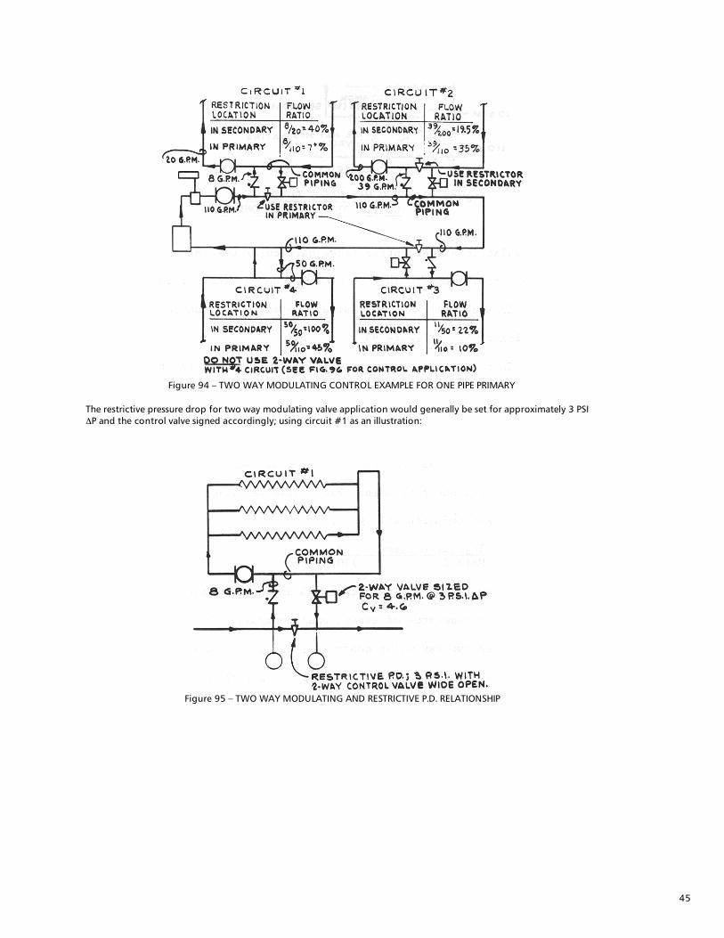
Figure 94 – TWO WAY MODULATING CONTROL EXAMPLE FOR ONE PIPE PRIMARY
The restrictive pressure drop for two way modulating valve application would generally be set for approximately 3 PSI ΔP and the control valve signed accordingly; using circuit #1 as an illustration:
Figure 95 – TWO WAY MODULATING AND RESTRICTIVE P.D. RELATIONSHIP

46
d. Three way valve application to one pipe primary main The control valve application that should be made to circuit #4 in Figure 94 would be 3 way bypass or diverting—and in the secondary circuit as described in Figure 92:
Figure 96 – THREE WAY BYPASS OR DIVERTING VALVE APPLICATION TO ONE PIPE PRIMARY MAIN
Three way valves will not often need to be applied to one pipe primary main secondary circuit control, because flow ratios will generally permit two way application. The bypass or diverting valve application is preferred over the mixing valve when applied in the secondary circuit because of secondary circuit pressure problems (see item 18 page 36 ). 26. One Pipe Primary Main - Chilled Water Several large central station distribution systems have been installed using one pipe chilled water distribution mains. Complete design satisfaction has been obtained. Design is sophisticated; requiring integrated attention to temperature-rise down the main and diversity factors. The heat transfer area size in the secondary can also be affected by the main temperature rise. Control of the secondary circuits would generally be established as two way valves in the “first secondaries” with 3 way application at the last secondary take-off.

47
Considerable installation (buried conduit) savings can be obtained with highly predictable results. 27. Primary-secondary application to “staged” construction. A large number of design plans prepared by Consultants are established for “staged” construction of schools, hospitals, factories, housing developments, etc. When primary-secondary design procedure is applied, the primary distribution system can be laid out full size; with cross over bridges installed for the future additions. Pumping and other equipment can be selected with complete predictability as to both initial and final results.
Figure 97 – STAGED P-S DESIGN
28. New Heating addition to existing conventional two pipe distribution system. Many plants, schools, garages, etc. require heating off “add on” facilities to an existing hot water heating system. Primary-secondary application will usually make the addition possible - without changing the already installed distribution system.
Example #1: An industrial plant requires heating of a new entry and watchman‘s structure (30 MBH). The new structure is located close to an existing return main for the present heating system. The return main is 2”, flowing approximately 40 GPM at 180º. The installation is diagrammed below for stop-start pump control:
Figure 98 – EXAMPLE #1 FLOW DIAGRAM
The new circuit is simply tapped into the existing return main; temperature control is achieved by thermostatic control of the secondary circuit pump. The following equipment selection criteria would apply: (1) Pipe sizing to 3 GPM = ¾” (2) Pump selection to 3 GPM and circuit head; “75” booster. (3) Radiation selection to 30 MBH at 180º supply

48
Example #2: A plant requires additional office space. The space is to be selectively cooled or heated using fan coil terminal units which require 140º mean water temperature for heating at 300 MBH load; a 15 ton cooling load is anticipated. An existing return main (180º) is located close to the proposed addition. The main is 3” size and flows 100 GPM. The basic “addition” flow diagram is shown in Figure 99.
Figure 99 – EXAMPLE 2 FLOW DIAGRAM
The new circuit is again tapped into the heating return main. The installation will not interfere with present distribution circulation and will selectively heat or cool by operation of a two position heat cool switch which activates either the heat injection pump or the chiller and its secondary pump. The following equipment selection would apply: (1) Pipe size to 45 GPM (15 ton @ 3 GPM/ ton) (2) chiller at 15 ton. (3) Chiller pump at 45 GPM and chiller P.D. (4) Secondary pump at 45 GPM and circuit P.D. (5) Injection pump at 300 MBH and 50º T = 12 GPM. (6) Injection flow rate not to exceed return main flow. In examples 1 and 2, the additional heating circuits have been tapped into existing return mains, using residual return heat, and in such a way that the original flow distribution has not changed. The only effect is increased temperature drop applied to the existing pipe circuit. The same application procedures can be used for process loads, new air handlers, etc. The only application limits are return main flow rates and temperatures as applied to the “addition” heat transfer requirements and, of course, existing boiler ability to handle the additional load.

49
Should return main “tapping” not be feasible because of location or new load requirements, the supply main can often be used. The common piping tap into the supply main will cause a temperature drop in supply water temperature which can often be overcome by simply raising the boiler supply water temperature. Example #3: The previous design example (#2) is used as a base; the only difference being that a 3” supply main at 40 GPM and 200º temperature is to be used as the heat tap source.
Figure 100 – EXAMPLE 3 FLOW DIAGRAM; HEAT SOURCE TAP INTO SUPPLY MAIN
The only difference between example 3 as compared with 2 will be a supply main temperature increase and a changed injection pump flow rate. A 300 MBH Load tap against a main flow rate of 40 GPM will establish a 15º temperature drop in the main. The boiler aquastat would then have to be reset to 215º supply. The new conditions at the common piping tap into the supply main are as below:
Figure 101 – CHANGED CONDITIONS @ INJECTION PUMP
The new injection pump selection will be for 300 MBH at 85º temperature difference (215 - 130 = 85). The required injection flow rate will only be 7.2 GPM; a #100 booster pump could be used.

50
New primary-secondary cross-over bridges can also be installed across existing supply and return mains. The additional cross-over flow requirement for the existing piping circuit can be held to a minimum by selection of the new terminal heat transfer equipment to a low mean water temperature requirement. Assuming the conditions established for example #2 are maintained except that a cross-over bridge is to be applied; the only change would be for an increased existing circuit flow of 12 GPM; as in figure 102.
Figure 102 – CROSS OVER BRIDGE APPLICATION T0 EXAMPLE 2
It will usually be found that the minor existing circuit flow increase requirement established by new cross-over bridges for system addition will not effect over-all system operation. Minimum flow increase is established by: 1. Selection of new secondary circuit heat transfer to low mean temperature requirements (140º forced convection). 2. Limitation of the new load. Many existing hot water circuits are designed to about 200º supply water temperature and 180º return. The existing network can be used for distribution of approximately three times its present heat conveyance ability by judicious application of primary secondary principles.

51
Example #4: An industrial plant requires a major addition at a point remote from an existing boiler plant. Existing heat generating capacity is sufficient; the limitation being flow capacity of the existing distribution piping.
Figure 103 – EXISTING DISTRIBUTION PIPING CONVENTIONAL 20º ΔT DESIGN
The existing distribution piping can be increased to the order of three times its original heat conveyance ability by an increase in design temperature drop. The increased design temperature drop can be attained by primary-secondary cross-over bridge control at each circuit distribution point, and by an increase in supply water temperature:
Figure 104 – INCREASED TEMP DROP BY P-S APPLICATION TO EXISTING DISTRIBUTION CIRCUIT PERMITS ADDITIONS
WHILE USING EXISTING CIRCUIT.
52
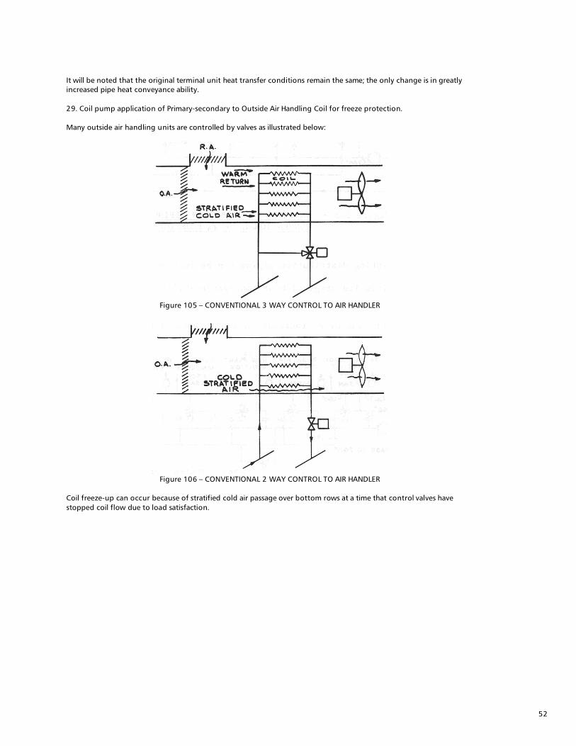
It will be noted that the original terminal unit heat transfer conditions remain the same; the only change is in greatly increased pipe heat conveyance ability. 29. Coil pump application of Primary-secondary to Outside Air Handling Coil for freeze protection. Many outside air handling units are controlled by valves as illustrated below:
Figure 105 – CONVENTIONAL 3 WAY CONTROL TO AIR HANDLER
Figure 106 – CONVENTIONAL 2 WAY CONTROL TO AIR HANDLER
Coil freeze-up can occur because of stratified cold air passage over bottom rows at a time that control valves have stopped coil flow due to load satisfaction.

53
Coil freeze, under these conditions, can be eliminated if continuous coil flow is maintained at all times--and despite valve controlling position. Continuous coil pumping drives water through the stratified cold area fast enough to prevent freeze. The water is then delivered to the stratified warm return air area where it is under continuous “reheat.” The net result is additional coil freeze protection. Already installed, conventionally controlled, coils can be converted to the pumped coil installation by provision of a pump and a common piping bypass as below:
Figure 107 – COIL PUMP ADDITION FOR FREEZE PROTECTION 3 WAY VALVE (COMPARE WITH FIGURE 105)
Figure 108 – COIL PUMP ADDITION FOR FREEZE PROTECTION 2 WAY VALVE (COMPARE WITH FIGURE 106)
In this application, continuous coil flow will be provided so long as the coil pump is in operation. To guard against inadvertent pump shut down, a flow switch is employed. This switch overrides normal control and throws the control valve wide open to the coil. The check or Flo Control insures that coil flow will occur under these conditions. Overheating would soon bring corrective action. The coil pump and common piping bypass are sized equal to or greater than flow rates corresponding to the initial full load coil and control valve flow selection points. The pump should be selected against the coil pressure drop and to a minimum head of 5’ (booster pumps to 2”) or to 10’ (larger line mounted). In order to positively prevent any possibility of pump motor overloads as might be caused by “seriesed” operation of the coil pump with the main distribution pump, the operating pump differential head should be checked with the valve in a wide open position. Should this head be less than approximately 5’ or I0’ (see previous reference) the balance valve illustrated on figures 107 and 108 should be “cocked” back until the necessary differential head is obtained.

Xylem Inc. 8200 N. Austin Avenue Morton Grove, Illinois 60053 Phone: (847) 966-3700 Fax: (847) 965-8379www.bellgossett.com
Bell & Gossett is a trademark of Xylem Inc. or one of its subsidiaries. © 2016 Xylem Inc. TEH-775A January 2013
1) The tissue in plants that brings water upward from the roots;2) a leading global water technology company.
We’re a global team unified in a common purpose: creating innovative solutions to meet our world’s water needs. Developing new technologies that will improve the way water is used, conserved, and re-used in the future is central to our work. We move, treat, analyze, and return water to the environment, and we help people use water efficiently, in their homes, buildings, factories and farms. In more than 150 countries, we have strong, long-standing relationships with customers who know us for our powerful combination of leading product brands and applications expertise, backed by a legacy of innovation.
For more information on how Xylem can help you, go to www.xyleminc.com
Xylem