price cents june - americanradiohistory.com · 2019-07-17 · universal tuner, model rj -12a, as...
TRANSCRIPT
Price 25 Cents
June 1948
..... ...... . . ...... ...... , ........
... , ........ .. ...... .. ... .1.410 ........ ...... .......... ...... . ..... y ...... .......
^ ....... ..... .01k" a , ..........
e s. ..... . .......... .... ............. f ...... 0+, ........... ........ ...... : ....
************** ******** :::::::"4 *******
***** 0 *** ** .......... .... .. .. 11) ............
/
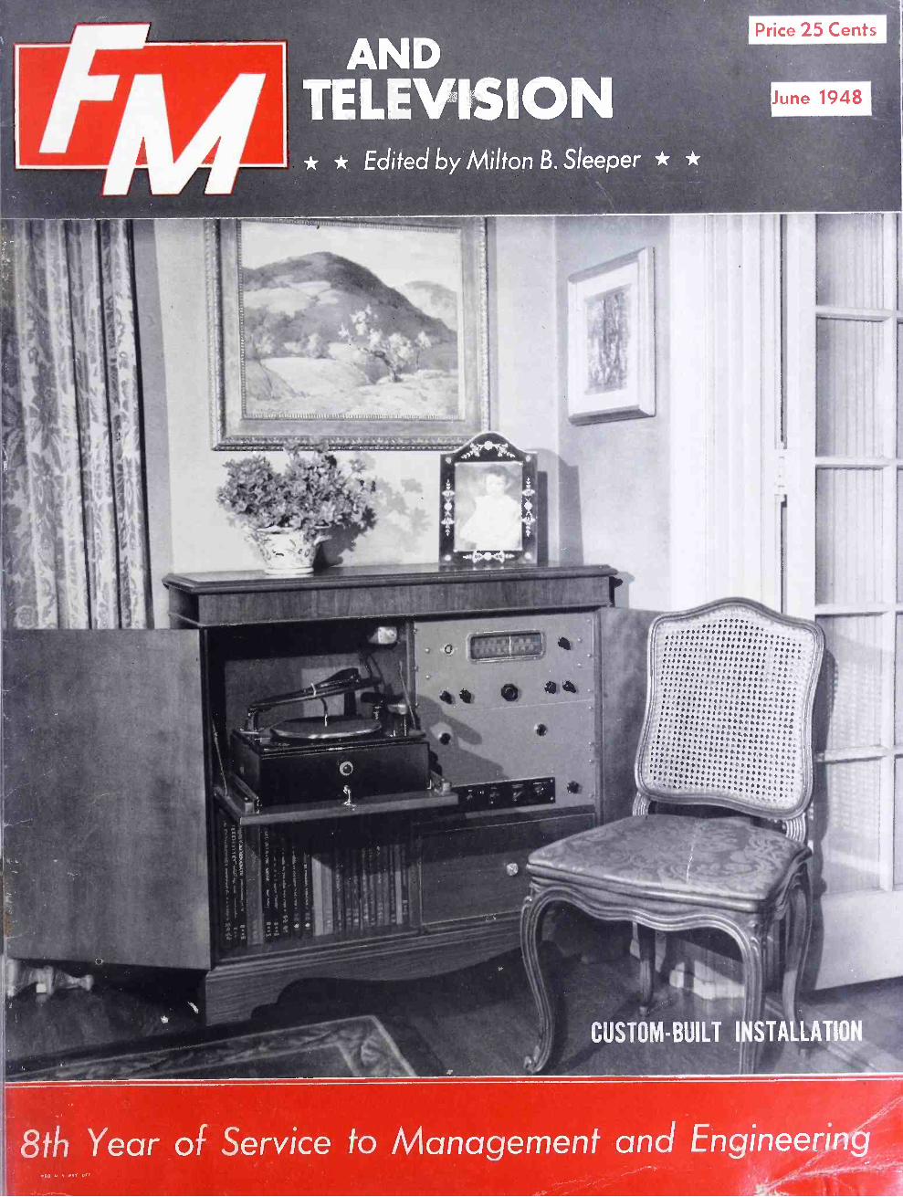
CUSTOM-BUILT INSTALLATION
8th Year of Service to Management and En -'X' '
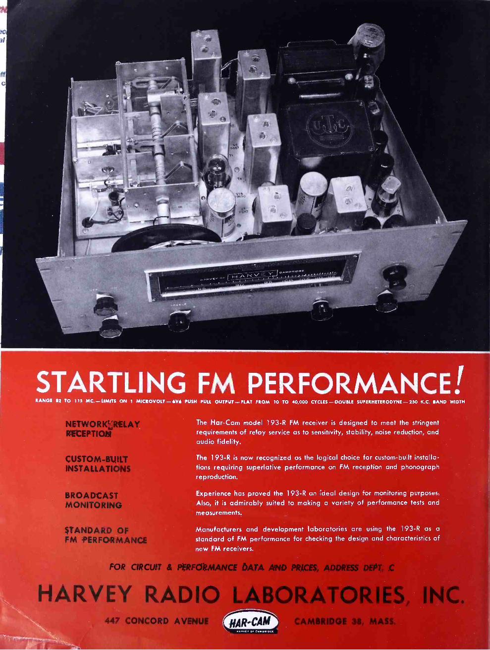
STARTLING FM PERFORMANCE! RANGE $2 TO 115 MC. - LIMITS ON 1 MICROVOLT - 6V6 PUSH PULL OUTPUT - FLAT FROM 10 TO 40,000 CYCLES - DOUBLE SUPERHETERODYNE - 250 K.C. BAND WIDTH
NETWORKtRELAY RECEPTION
CUSTOM -BUILT INSTALLATIONS
BROADCAST MONITORING
STANDARD OF FM PERFORMANCE
The Har -Cam model 193 -R FM receiver is designed to meet the stringent requirements of relay service as to sensitivity, stability, noise reduction, and
audio fidelity.
The 193 -R is now recognized as the logical choice for custom -built installa- tions requiring superlative performance on FM reception and phonograph reproduction.
Experience has proved the 193 -R an ideal design for monitoring purposes.
Also, it is admirably suited to making a variety of performance tests and
measurements.
Manufacturers and development laboratories are using the 193 -R as a
standard of FM performance for checking the design and characteristics of new FM receivers.
FOR CIRCUIT & PERFORMANCE DATA AND PRICES, ADDRESS DEPT.
HARVEY RADIO LABORATORIES, INC. 41.
447 CONCORD AVENUE CAMBRIDGE 38, MASS.
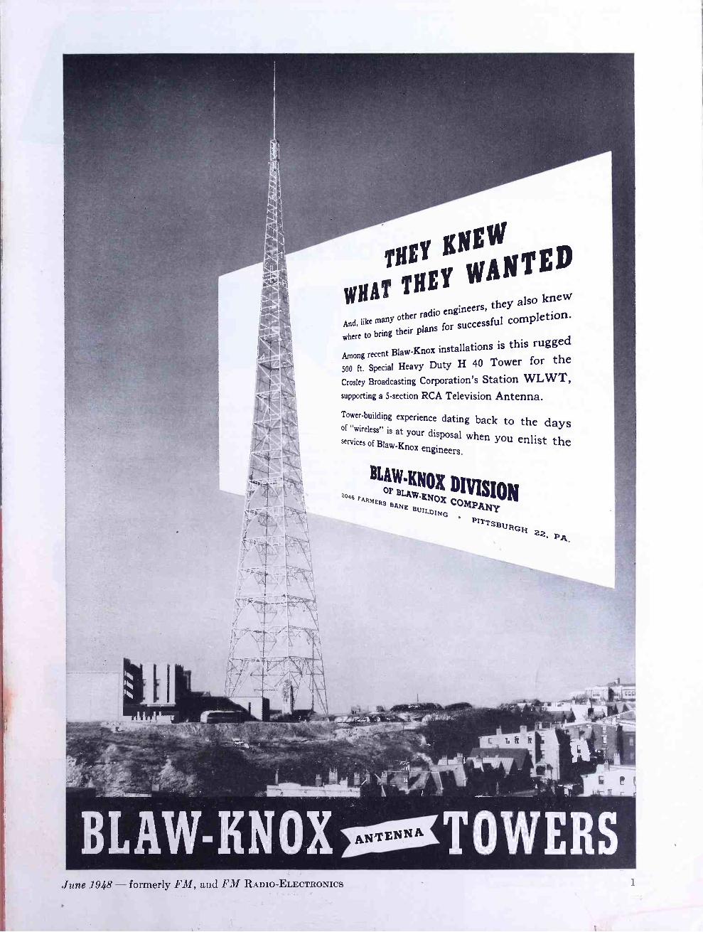
THEY ANEW
WANTED THEY
WHAT
And, like many other radio engineers, they also knew
where to bring their plans for successful completion.
Among recent Blaw -Knox installations is this rugged
500 ft. Special Heavy Duty H 40 Tower for
Broadcasting Corporation's Station WLWT, supporting a 5- section RCA Television Antenna. Tower- building experience dating back to the days of "wireless" is at your disposal when you enlist the services of Blaw -Knox engineers.
BLAw'KNOX DI VISION OF 2oa5 FARMERS
BANK Dox COMPANY BUILDING
22' pA
BLAW-KNOX TOWERS June 1948 - formerly FM, and FM RADIO -ELECTRONICS

iklA FNTV RpY1HE0N SPEECH E4U \PMENS
For the last word in complete, up -to- the -minute facilities . .. or simple, low -cost equipment
to suit your limited requirements ... Look to RAYTHEON for All Your Needs
RC -11 STUDIO CONSOLE
NOW WITH CUE POTS FOR TWO TURNTABLES
Provides complete high -fidelity speech input facilities with all control, ampli- fying and monitoring equipment in one cabinet. Seven built -in pre -amplifiers, nine mixer positions, cue attenuators for two turntables. Simple, positive controls reduce operational errors. Frequency response -2 DB from 30 to 15,000 cycles; Distortion -less than 1% from 50 to 10,000 cycles; Noise Level -minus 65 DB's or better. Meets all FCC requirements for FM.
RR -30 REMOTE AMPLIFIER 3 CHANNEL A lightweight, easy -to -carry combination of amplifier and power supply -simple and quick to set up. Provides three high -fidelity channels, excellent frequency response, high over -all gain.
RP -10 PROGRAM AMPLIFIER High gain, low distortion, excellent frequency characteristics. For rack or cabinet mounting.
RPC -40 PORTABLE CONSOLETTE Ideal for remote pickups yet complete enough to serve as a studio console. Four input chan- nels for microphones or turntables, high level mixing, two output lines. Two RPC -40's inter- connected provide 8- channel mixing -a fea- ture of special interest to new TV stations planning future expansion.
RR -10 REMOTE AMPLIFIER SINGLE CHANNEL
A complete, self -contained unit with built -in power supply. An excellent low -cost amplifier for remote pick- ups requiring only one high -fidelity channel.
RL -10 VOLUME LIMITER Engineered for high - fidelity AM, FM or TV speech input. Increases average percentage modulation without distortion.
RAYTHEON MANUFACTURING COMPANY WALTHAM 54, MASSACHUSETTS
Industrial and Commercial Electronic Equipment, FM, AM and TV
Broadcast Equipment, Tubes and Accessories
BOSTON CHATTANOOGA
CHICAGO DALLAS
LOS ANGELES
NEW YORK SEATTLE
WASHINGTON
EXPORT SALES AND SERVICE IN FOREIGN COUNTRIES
Raytheon Manufacturing Company, 50 Broadway, New York 4, N. Y., WH. 3 -4980

AND TELEVISION * * Edited by Milton B. Sleeper * *
Formerly, F:11 MAGAZINE and FM RADIO-ELECTRON I(a VOL. 8 JUNE, 1948 ti O. 6
COPYRIGHT 1948, by Milton B. Sleeper
CONTENTS WHAT'S NEW THIS MONTH
Set Production - Marine FM - Limited Corn mon Carriers
FCC VIEWS THE FUTURE OF FM & TV Hon. Wayne Coy
CUSTOM -BUILT INSTALLATIONS Milton B. Sleeper
RELAY PICKUP EQUIPMENT Frederick T. Budelman
GETTING WPIX ON THE AIR F. M. Flynn
AF CIRCUIT EQUALIZER I. Allen Mitchell
TV ANTENNAS Gardiner Greene
S -T LINK FOR 920 -960 MC. D. J. Nigg
SPECIAL DEPARTMENTS Telenotes Products & Literature Special Services Directory Professional Directory Spot News Notes News Pictures
15
16
20
26
28
31
32
6 7 8
12 22 23
THE COVER DESIGN AND CONTENTS OF FM AND TELEVISION MAGAZINE ARE FULLY PROTECTED BY U. S. COPYRIGHTS, AND MUST NOT BE REPRODUCED IN ANY
MANNER OR IN ANY FORM WITHOUT WRITTEN PERMISSION
MILTON B. SLEEPER, Editor and Publisher CHARLES FOWLER, Business Manager STELLA DUGGAN, Production Manager
RICHARD H. LEE, Advertising Manager LILLIAN BENDROSS, Circulation Manager
Published by: FM COMPANY Publication Office: 264 Main St., Great Barrington, Mass. Tel. Great Barrington 500 Advertising Department: 511 Fifth Avenue, New York 17, Tel. VA 6 -2483 FM Magazine is issued on the 20th of each month. Single copies 25¢ - Yearly subscription in the U. S. A. $3.00; foreign $4.00. Sub- scriptions should be sent to FM Company, Great Barrington, Mass., or 511 Fifth Avenue, New York 17, N. Y. Contributions will be neither acknowledged nor returned unless accompanied by adequate postage, packing, and directions, nor will FM Magazine be responsible for their safe handling in its office or in transit. Payments are made upon acceptance of final manuscripts.
AND TELEVISION / L . Fd.4.f!:r hldmn ti: !cejxr. t
COSIatEORf IMSTALLAD011
86 Year oí Service to Monugernenf and Engineering
THIS MONTH'S COVER Somehow, the idea has seeped
into the radio industry that the public is more concerned with the price of receivers than what comes out of the speakers. Because promotion was concen- trated on cheap table models, 12,000,000 were bought in 1947.
As a result, it is difficult for people to find sets capable of furnishing real musical entertain- ment. So difficult, in fact, they have to be built to order. But the demand is increasing, and cus- tom set -building is growing to substantial volume. This month's cover shows a particularly fine installation in the home of A. H. Sherin, Summit, N. J. The loud- speaker is shown on page 16.
FM ASSOCIATIOdV
Second Annual Convention SEPTEMBER 27 -28 -29
Hotel Sheraton CHICAGO, ILL.
OPEN TO ALL Interested in Radio's Rapidly -
Growing Art The FMA Convention, following the man- date of the organization's By -Laws, will cover the "general problems incident to FM operations." No other Trade Associa- tion meeting this year is designed to em- brace the entire FM field, plus Facsimile.
Programming an FM Station in all its phases - duplication, special events, com- munity interest, etc.... Promotion .
Dealer Cooperation ... Selling FM time ... Engineering ... Talent ... The Busi- ness Office ... ALL will be covered.
REGISTRATION FEE
$20 per person before Aug. 15 $25 per person after Aug. 15
Register Early Write
FMA HEADQUARTERS, 101 Munsey Bldg. Washington 4, D. C.
Entered as second -class matter, August 22, 1945, at the Post Office, Great Barrington, Mass.. under the Act of Mardi 3. 1879. Additional entry at the Post Office, Concord, N. H. Printed in the U. S. A.
MEMBER. AUDIT BUREAU OP CIRCULATIONS
CRYSTALS
BUILT TO YOUR SPECIFICATIONS
Crystal users appreciate the complete service James Knights Co. offers.
If you have a special crystal problem, James Knights is equipped to build crystals to your exact specifications -no matter what they may be. Because of a
special production line for short runs, the price is right- whether you need one, ten or several thousand crystals!
In addition, James Knights fabricates a complete line of crystals to meet every ordinary need - precision built by the most modern methods and equipment.
Fast service is yours, too! Two com- pany planes save hours when speed is
important. Your inquiries -and crystal problems are invited.
Send For New James Knights Catalog
JK 11/2" Doughnut Quartz Crystal
7e JAMES KNIGHTS eo
SANDWICH, ILLINOIS
C G1 CI a'traa a
I
ONO SO
11%it.4 1
I
. RADIO SET PRODUCTION Z. MOBILE COMMUNICATIONS 3. LIMITED COMMON CARRIERS
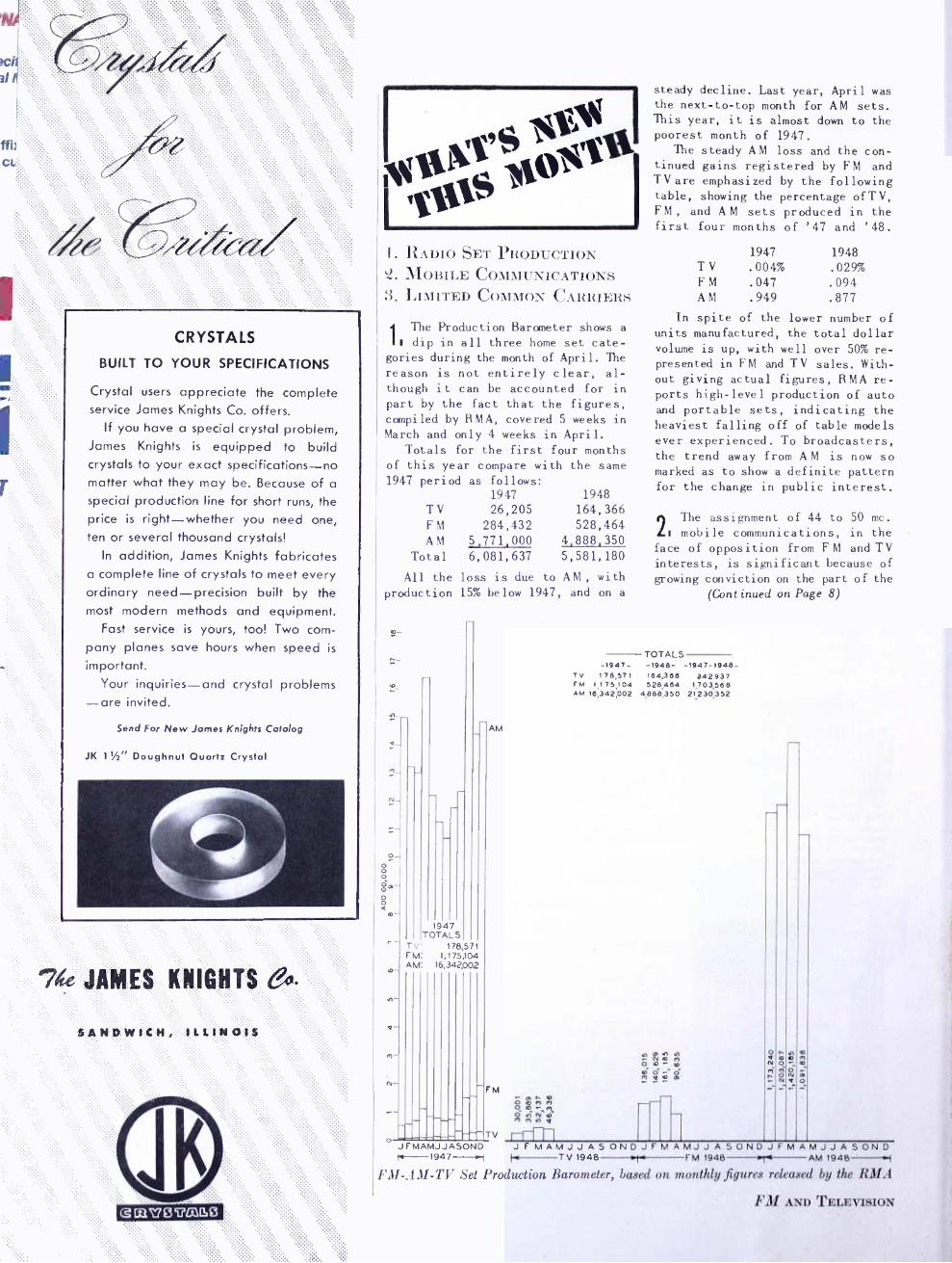
The Production Barometer shows a II dip in all three home set cate-
gories during the month of April. The reason is not entirely clear, al- though it can be accounted for in part by the fact that the figures, compiled by RMA, covered 5 weeks in March and only 4 weeks in April.
Totals for the first four months of this year compare with the same 1947 period as follows:
1947 1948 T V 26,205 164,366 F M 284,432 528,464 AM 5,771,000 4,888.350
Total 6,081,637 5,581,180 All the loss is due to AM , with
production 15% below 1947, and on a
AM
947 TOTALS
TV 178,57 FM: , 75104 AM: 16,342,002
steady decline. Last year, April was the next -to -top month for AM sets. This year, it is almost down to the poorest month of 1947.
The steady AM loss and the con- tinued gains registered by FM and TV are emphasized by the following table, showing the percentage of TV, FM, and AM sets produced in the first four months of '47 and '48.
1947 1948 TV .004% .029% FM .047 .094 AM .949 .877
In spite of the lower number of units manufactured, the total dollar volume is up, with well over 50% re- presented in FM and TV sales. With- out giving actual figures, RMA re- ports high -level production of auto and portable sets, indicating the heaviest falling off of table models ever experienced. To broadcasters, the trend away from AM is now so marked as to show a definite pattern for the change in public interest.
2The assignment of 44 to 50 mc. . mobile communications, in the
face of opposition from F M and TV interests, is significant because of growing conviction on the part of the
(Cont inued on Page 8)
TOTALS -1947- -1948- -1947 -1948-
TV 178,571 164,366 342937 FM I 1 75,104 528,484 1,703,588 AM 16,342,002 4,888,350 21230,352
r Ñ O m ^ O
O gp n1 O
Mrin° Y
o a N
r n ó m Ñ
h o_
O N O
JFMAMJJASOND JFMAMJJASONDJFMAMJJASONDJFMAMJJASOND tt- 1947 -.1 Fr TV 1948 r FM 1948 ' AM 1948 --{ ¡ "if- .Li! -TV Set Production Barometer, based on monthly figures released by the RMA
FM AND TELEVISION

BROWNING SCORES AGAIN!
NOW THE FAMOUS RJ -12
HAS NEW ENGINEERING
REFINEMENTS -PLUS A NEW, LOWER PRICE
INCE 1946, the performance of the BROWNING RJ -12 FM -AM tuner has
been winning friends and influencing more people to buy them in preference to any other type.
But because BROWNING equipment is "engineered for engineers ", we have never stopped our search for ways to raise the standards set by the RJ -12.
Now, we're ready with the new model: the RJ -12A. Dealers, custom set -builders, and engineers who have heard the RJ -12A are unanimous in calling it a "hot set ". They say frankly that they've never heard any FM -AM tuner that can equal it.
FM sensitivity is remarkable, noise - elimination is extremely effective, and there's no drift after warm -up. In short, it is the Armstrong FM circuit at its very best.
AM performance is equally outstanding. High -gain RF tuning, triple -tuned IF's, a 1N34 crystal detector, and new miniature tubes all contribute to enjoyable reception that runs rings around ordinary AM models.
Added features for custom set - builders are small size, separate power supply, a Phono position on the band switch, and one volume control for FM, AM, and the phonograph.
Write for details, performance curves, and prices:
BROWNING LABORATORIES, INC.
Engineers and Manufacturers
WINCHESTER MASSACHUSETTS
Canadian Representatives
Measurements Engineering, Ltd. Armprior, Ontario
UNIVERSAL TUNER, MODEL RJ -12A, AS ILLUSTRATED
POWER SUPPLY UNIT, MODEL PF -12, FOR ABOVE
RACK PANEL TUNER, MODEL RJ -14A, WITH POWER SUPPLY
INFORMATION ON THE RJ -12A TUNER
The RJ -12A tuner covers 88 to 108 mc. and 530 to 1,650 kc. It can be used with any high -fidelity amplifier and speaker. Operating voltages for the tuner can be taken from the ampli- fier, or furnished from a BROWNING PF -12 power supply.
Provisions are made for using the RJ -12A in combination with a phonograph and dynamic noise suppressor.
On FM, less than 10 microvolts signal produces a 30 db noise reduction. Audio response is flat within 11/2 db from 20 to 15,000 cycles.
On AM, sensitivity is 5 microvolts; triple -tuned IF's give a flat -topped characteristic extending the audio range to re- sponse flat within 3 db from 20 to 6,600 cycles.
Separate RF and IF systems for FM and AM eliminate coil switching. FM antenna serves for AM also.
Tubes: three 6AU6, one 7F8, one 6SK7, one 6SG7, two 6SJ7, one 6H6, one 6SA7, one 6E5 or 6U5, one 1N34 crystal detector.
Model RJ -14A includes a 19 -in. rack panel and the power supply.
June 1948 - formerly FM, and FM RADIO -ELECTRONICS 5
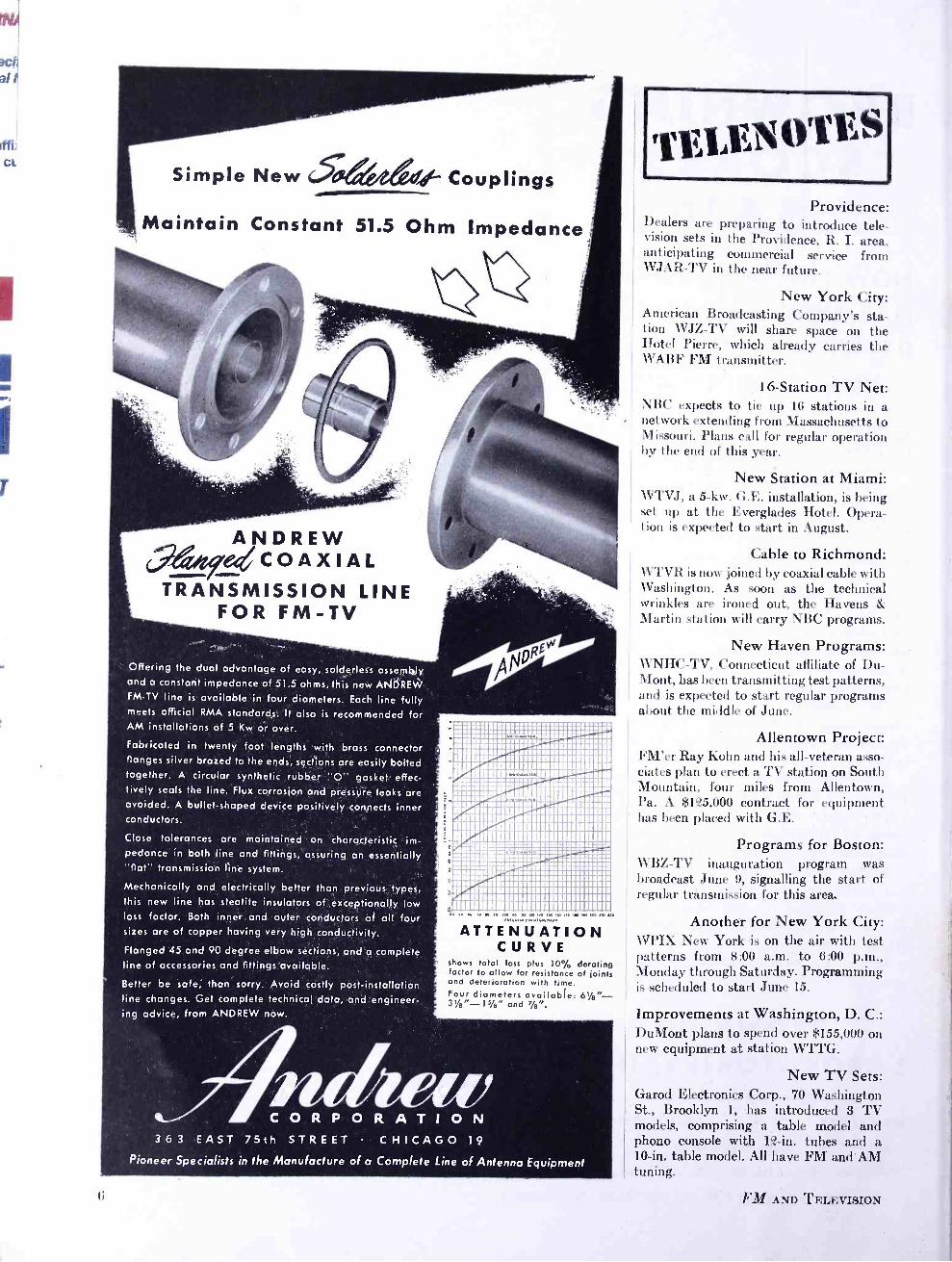
Simple New d-- Couplings
Maintain Constant 51.5 Ohm Impedance
ANDREW P,eCOAXIAL
TRANSMISSION LINE FOR FM -TV
Offering the dual advantage of easy, solderless assembly and a constant impedance of 51.5 ohms, this new ANDREW FM -TV line is available in four diameters. Each line fully meets official RMA standards. It also is recommended for AM installations of 5 Kw or over.
Fabricated in twenty foot lengths with brass connector flanges silver brazed to the ends, sections are easily bolted together. A circular synthetic rubber "O" gasket effec- tively seals the line. Flux corrosion and pressure leaks are avoided. A bullet- shaped device positively connects inner conductors.
Close tolerances are maintained on characteristic im- pedance in both line and fittings, assuring an essentially "flat" transmission line system.
Mechanically and electrically better than previous, types, this new line has steatite insulators of exceptionally low loss factor. Both inner and outer conductors of all four sizes are of copper having very high conductivity.
Flanged 45 and 90 degree elbow sections, and a complete line of accessories and fittings available.
Better be safe, than sorry. Avoid costly post- installation line changes. Get complete technical data, and engineer- ing advice, from ANDREW now.
..:':':: . i._ 1 dII..C.._ .....II I-'- i .u YN ..ti.l.. ..... üiiúiitr_';l¡iiiliiiÚiiuöñirii0
lmuWa111111
1
11e
a Vu0 ®® nS ij -
PPy ñ .r111111tI1It11I1
uáliiliiiillililli nrnin uuummu .41122t11220®.0 :.:.
11111111111111122111111 iiiiprui .......................
u..nan.......... .... u 00 % Iiililillï IÌIIÏ Ìl Illlllllll
611uñ1ii11i111l,i11111111 .»» ND ..,...KU .»...»...,. .. k
ATTENUATION CURVE
shows total loss plus 10% derafing factor to allow for resistance of joints and deterioration with time. Four diameters available: bt /e = 31/4 -1s /e" and Ye".
(;
C O R P O R A T I O N
363 EAST 75th STREET CHICAGO 19
Pioneer Specialists in the Manufacture of a Complete Line of Antenna Equipment
I vfEIA1
¡ ØÎES ,\ Providence:
Dealers are preparing to introduce tele- vision sets in the Providence, R. I. area, anticipating commercial service from WJAR -TV in the near future.
New York City: American Broadcasting Company's sta- tion WJZ -TV will share space on the Hotel Pierre, which already carries the \VABF FM transmitter.
16- Station TV Net: NBC expects to tie up 16 stations in a network extending from Massachusetts to Missouri. Plans call for regular operation by the end of this year.
New Station at Miami: WTVJ, a 5 -kw. G.E. installation, is being set up at the Everglades Hotel. Opera- tion is expected to start in August.
Cable to Richmond: WTVR is now joined by coaxial cable with Washington. As soon as the technical
tinkles are ironed out, the Havens & Martin station will carry NBC programs.
New Haven Programs: WNHC -TV, Connecticut affiliate of Du- Mont, has been transmitting test patterns, and is expected to start regular programs about the middle of June.
Allentown Project: FM'er Ray Kohn and his all- veteran asso- ciates plan to erect a TV station on South Mountain, four miles from Allentown, Pa. A $125,000 contract for equipment has been placed with G.E.
Programs for Boston: WBZ -TV inauguration program was broadcast June 9, signalling the start of regular transmission for this area.
Another for New York City: WPIX New York is on the air with test . patterns from 8:00 a.m. to 6:00 p.m., Monday through Saturday. Programming is scheduled to start June 15.
Improvements at Washington, D. C.: DuMont plans to spend over $155,000 on new equipment at station WTTG.
New TV Sets: Garod Electronics Corp., 70 Washington St., Brooklyn 1, has introduced 3 TV models, comprising a table model and phono console with 12 -in. tubes and a 10 -in. table model. All have FM and AM tuning.
FM AND TELEVISION
%)%tØ1)11o1 '\
LITE1tiIt3lt A
HIGH VOLTAGE INDICATOR : Inexpensive Neon indicator for 1,600 to 15,000 volts A.C. for television power supplies and other high voltage circuits. Bulletin 500. Industrial Devices, Inc., Edgewater, N. J. TUBE CHECKER: Design for testing all types of receiving tubes with 4, 5, 6, 7, and 8 pin standard, 5 pin small, 7 and 9 pin miniature and lockin tubes. Type Y TW -1. Bulletin CT. General Electric Co., Electronics Department, Syracuse, N. Y. SHRINK -FIT TuBncG: Insulated tubing in various sizes and colors can be expanded by dipping in a solution. After drying, it shrinks to a tight fit on the wire. Bulletin OCS. Walter L. Schott Co., 9306 Santa Monica Blvd., Beverly Hills, Calif. VHF POWER AMPLIFIER TUBE: Beam pentode of instant- heating design for portable and mobile transmitters. As Class "C" amplifier, delivers 1.25 watts at 100 mc. Type 3B4. Bulletin HR -133. Hytron Radio & Electronics Corp., 76 Lafayette St., Salem, Mass. MATCHING TRANSFORMER: Broad -band transformer for matching Measurements Model 80 Standard Signal Generator de- signed for use in conjunction with Meas- urements Model 80 Standard. Can be used also for matching receivers having an input impedance of 300 ohms to a coaxial line of 72 ohms. Type M- 286. Bulletin CM6. Measurements Corp., Boonton, N. J. MICROWAVE UNITS: Slotted section and probe combinations for a standard size of waveguides and coaxial lines, for bands between 1,000 and 40,000 mc. Type PRD. Bulletin RH. Polytechnic Research & Development Co., 66 Court St., Brooklyn 2, N. Y. LIGHTNING ARRESTERS, TERMINAL: 16- page catalog of lightning arresters for radio and telephone entrance lines, molded terminal strips, and neon voltage indicators. Bulletin 200 -A. L. S. Brach Mfg. Corp., Central Avenue, Newark, N. J. BIBLIOGRAPHY: "Electric Engineering Master Index," 320 pages, compiled from radio and electronics publications cover- ing 15,000 listings under g50 special heads, edited by Frank A. Petraglia. Publica- tion 254 - Price $17.50. Electronics Re- search Publishing Co., 2 West 46th St., New York 19, New York. CIRCUIT TESTER: Pocket -size meter pro- vides 31 AC -DC range to 6,000 volts, 600 milliamperes, 70 db, and 5 megohms. Series 40. Bulletin NE -6. Precision Ap- paratus Co., Inc., 92 -27 Horace Harding Blvd., Elmhurst, L. I. TV ANTENNA: Adjustable to any channel and designed for a stack array. Trade name "Telebeam." Bulletin 11. Cole - Worner Corp., Dayton, Ohio.
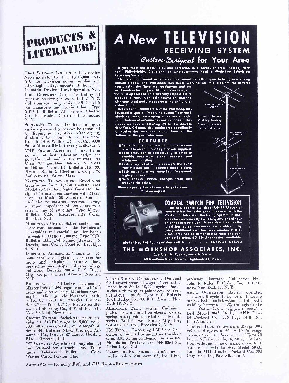
ANew TELEVISION RECEIVING SYSTEM
G'wsta..2).44.ec2 for Your Area If you want the finest television reception in a particular area- Boston, New
York, Philadelphia, Cleveland, or wherever -you need a Workshop Television Receiving System.
The so- called "broad band" antennas cannot be relied upon to bring in a strong enough signal. The Workshop has been working on this problem for several years, using the finest test equipment and the most modern techniques. At the present stage of the art it appears to be practically impossible to produce a truly high -gain television antenna with consistent performance over the entire tele- vision band.
Rather than "compromise," the Workshop has designed a special "receiving system" for each television area, employing a separate high - gain, 3- element antenna for each channel. This means we have a receiving system for Boston, New York, Chicago, etc., engineered specifically to receive the maximum signal from all the stations in the particular area.
FEATURES Separate antenna arrays all mounted on one
mast. Universal mounting brackets supplied. Each array can be individually oriented to
provide maximum signal strength and minimum ghosting.
Each array is fed with a separate RG -59/U transmission line - reduces noise pickup.
Each array is a well -matched, 3- element, high -gain antenna.
New coaxial switch changes from one array to the other.
Please specify the channels in your area. Price on request
TV69 CHANNEL 4
WeZ. TV
Typical of the new
Workshop Receiving
System is this system
for the Boston area
TV 177 CHANNEL 7
WNACTV
COAXIAL SWITCH FOR TELEVISION This new coaxial switch for RG -59/U coaxial
transmission line is designed to be used with the Workshop Television Receiving System. It pro- vides for conveniently switching any one of four antennas to a receiver. In addition, it solves the television sales demonstration problem. By using additional switches, any number of tele- vision sets can be demonstrated from one con- venient location. RG -59/U connectors available.
Model No. R -4 Four -position switch . . . . List Price $ 15.00
THE WORKSHOP ASSOCIATES, INC. Specialists in High-frequency Antennas
65 Needham Street, Newton Highlands 61, Mass.
TUNED- RIBBON REPRODUCER: Designed for Garrard record changer. Described as linear from 50 to 10,000 cycles. Jewel - stylus with 24 gram point- pressure. Out- put about - 30 db. Type 79 -G. Bulletin 16 -H. Audak Co., 500 Fifth Avenue, New York 18, N. Y. MINIATURE TUBE GUARD: Cadmium - plated post, mounted on chassis, carries spring to keep miniature tube firmly in its socket. Bulletin 254. Stayer Mfg. Co., 254 Atlantic Ave., Brooklyn 2, N. Y. FM TUNER: Three -gang FM Vane Con- denser is designed to mount on the shaft of an AM tuning condenser. Bulletin ES. Modulation Products Co., 509 23rd St., Union City, N. J. TELEVISION EXPLAINED: Title of a how -it- works book of 200 pages, 8% by 11 ins.,
June 1948 - formerly FM, and FM RADIO -ELECTRONICS
profusely illustrated. Publication N61. John F. Rider, Publisher, Inc., 404 4th Ave., New York 16, N. Y. AUDIO OSCILLATOR: Battery operated oscillator, 2 cycles to 20 kc. in 4 decade ranges. Rated as flat within ± 1 db, with stability between ± 3% throughout the range. Output is 5 volts into a 10,000 ohm load. Model 204A. Bulletin ANP. Hew- lett- Packard Co., 395 Page Mill Rd., Palo Alto, Calif. VACUUM TUBE VOLTMETER : Range .001 volts at 2 cycles to 20 kc. Useful range extends to 50 kc. Accuracy ± 3% to 20 kc., f 7% from 20 kc. to 50 kc. Calibra- tion reads rms value of a sine wave. A db scale reads -12 to +2. Model 404A. Bulletin M14. Hewlett- Packard Co., 395 Page Mill Rd., Palo Alto, Calif.
7
Special Services Directory
METHODS ENGINEERS Materials & Methods engineers in America's leading manufacturing plants use Topflight's Printed Cellophane, Self - Adhesive Tape to meet A -N specs. - assembly line - follow through - instruction labels. Easy to Apply.
TOPFLIGHT TAPE CO. YORK PA.
THE WORKSHOP ASSOCIATES
INCORPORATED
Specialists in high- Frequency Antennas
66 Needham St., Newton Highlands, Mass. Bigelow 3330
l.udlForn- ui/ SPEECH INPUT EQUIPMENT
U. S. Recording Co. 1121 Vermont Avenue Washington 5, D. C.
District 1640
TOWER LIGHTS OBSTRUCTION LIGHTS
CODE FLASHERS
HUGHEY & PHILLIPS 326 North La Cienega Blvd.
Los Angeles 36, Calif.
HIGH QUALITY REPRODUCTION
ENGINEERING and PRODUCTION The KLIPSCH SPEAKER SYSTEM
Standard and Custom Built Types for Private Homes, Auditoriums, Hotels, Theatres
BROCINER ELECTRONICS LABORATORY REgent 7 -6794
1546 -F SECOND AVENUE, NEW YORK 28
ELECTRONIC ENGINEERING MASTER INDEX
CON 1 AI N:, the 1n0tll complete bibliography avail- able on Frequency Modulation, Television, UHF. Broadcasting, Radar, and over 400 other topics.
1925 -1945 edition E17.50
1935 -1945 edition E 6.00
Descriptive literature on request
ELECTRONICS RESEARCH PUBLISHING CO. Dept. A 2 West 46th St., N. Y. 19
ti
WHAT' S, NEW THIS MONTH (Continued from Page 4)
FCC that 2 -way FM has become an es- sential service to "public interest, convenience, and necessity ".
This attitude on the part of the Commission is further emphasized in the following comment received from Jeremiah Courtney, former FCC As- sistant General Counsel, and now of Courtney, Krieger & Jorgensen, 1707 H Street, N.W., Washington, D.C.:
Striking testimonial to the in- creasing attention now being paid by the Federal Communications Commission to non -broadcast radio problems is to be found in analysis of the novel conditions under which the new mari- time mobile radio service to serve private operational and business needs of ships was recently author- ized by the FCC.
To appreciate the significance of the FCC's extraordinary action in the marine field, it is necessary to contrast the labor pains that gener- ally characterize the birth of a new radio service against the practi- cally painless birth of the maritime mobile radio service.
The normal new radio service must first strive to obtain the use of certain of the frequencies assigned for all general experimental pur- poses. Successful in that quest, the applicant receives an authorization in terms cancellable "at any time without advance notice or hearing if, in the opinion of the Commission, such action is necessary." This is no
surprise, of course, because before his experimental application would even be considered by the Commission, the applicant has to file a statement that he would not construe its grant to mean "that, in the event the ex- perimentation proves successful, either the particular frequencies authorized or any others will be al-
located to the service developed for
use on a permanent or commercial ba- sis." (Section 5.20, FCC Experimen- tal Rules)
However, the applicant is then in
position to use radio and to con- struct his land station and install his mobile units, provided he is
willing to risk the equipment invest-
ment. The financial risk cannot be
written off because it is always possible that the FCC might later decide that the applicant's parti- cular experimental use of radio was
not in the public interest; and the
applicant's experimental authoriza-
tion would then be withdrawn. This is
the uneasy transition that has marked
the passage of police, railroad, bus,
and taxicab use of radio from experi-
mental to regular services, to men-
tion just a few prominent examples.
It is well established that the ever -present danger of loss of equip- ment investment has retarded the prompt development of all services that have been required to pass this experimental stage without assurance of ultimate regularization. On the other hand, for the FCC to decide in advance of any experimentation that a new service will click, and justify the assignment of frequencies on a regular basis, requires no little as- surance. Yet that is precisely what the Commission did in establishing the maritime mobile service. The pub- lic announcement of its decision to establish the service expressly stat- ed:
"The Commission today announced that it had decided to establish on a regular basis at the earliest oppor- tunity a VHF (very high frequency) radiotelephone maritime mobile ser- vice to serve the operational and business needs of ships. The Commis- sion also announced that in connec- tion with this decision it had grant- ed applications for certain land radiotelephone stations and a number of associated radiotelephone sta- tions aboard tugboats.
* * * ** ** ** * * * **
"The grants here concerned are de- signated as class 2 experimental. However, the Commission emphasized that these grants are not for the purpose of determining whether a pro- posed service should be established on a regular basis, but rather are to
be construed as being of an interim character to permit operation in or- der that the Commission may thereby be furnished with information needed for the formulation of rules to gov- ern the service on a regular basis."
The Commission's extraordinary de- parture from long -established policy in this case is only emphasized by
the fact that the first marine appli-
cations filed some twenty months earlier by non -common carrier organ- izations (Foss Launch & Tug Co. of Seattle, Washington; Meseck Towing Lines, Inc. and Moran Towing & Trans- portation Co. of New York, N.Y.) for
experimental authorizations had been designated for public hearing. Not without reason, therefore, did the
Commission's own announcement de-
scribe the action taken as "excep- tional in the marine field."
Why was this exceptional action taken? Certainly not because the
problems that attend regularization
of the maritime mobile service were
any less acute than those attending the establishment of the police,
railroad, bus, or taxi radio ser-
vices, all of which were required to
pass through an entirely experimental
stage. If anything, the marine pro -
(Continued on Page 12)
FM AND TELEVISION
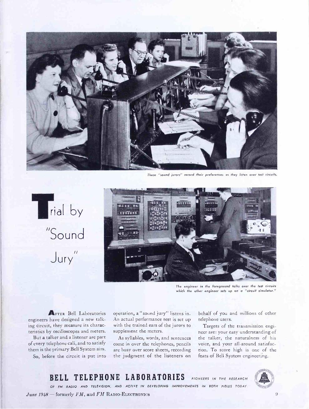
Tal by II
S o u n c
J ur y
These "sound jurors" record their preferences as they listen over test circuits.
AFTER Bell Laboratories engineers have designed a new talk- ing circuit, they measure its charac- teristics by oscilloscopes and meters.
But a talker and a listener are part of every telephone call, and to satisfy them is the primary Bell System aim.
So, before the circuit is put into
The engineer in the foreground talks over the test circuits
which the other engineer sets up on a "circuit simulator."
operation, a "sound jury" listens in. An actual performance test is set up with the trained ears of the jurors to supplement the meters.
As syllables, words, and sentences come in over the telephones, pencils are busy over score sheets, recording the judgment of the listeners on
BELL TELEPHONE LABORATORIES OF FM RADIO AND TELEVISION, AND ACTIVE IN DEVELOPING
June 1948 - formerly FM, and FM RADIO- ELECTRONICS
behalf of you and millions of other telephone users.
Targets of the tránsmission engi- neer are: your easy understanding of the talker, the naturalness of his voice, and your all-around satisfac- tion. To score high is one of the feats of Bell System engineering.
PIONEERS IN THE RESEARCH
IMPROVEMENTS IN BOTH FIELDS TODAY.
9
ffi) Cu
1
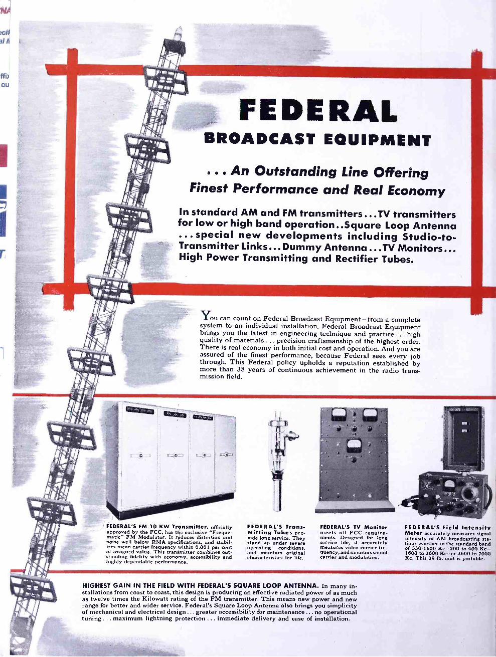
FEDERAL BROADCAST EQUIPMENT
Finest Performance and Real Economy In standard AM and FM transmitters...TV transmitters for low or high band operation ..Square Loop Antenna ... special new developments including Studio -to- Transmitter Links... Dummy Antenna ...TV Monitors... High Power Transmitting and Rectifier Tubes.
You can count on Federal Broadcast Equipment -from a complete system to an individual installation. Federal Broadcast Equipment brings you the latest in engineering technique and practice ... high quality of materials ... precision craftsmanship of the highest order. There is real economy in both initial cost and operation. And you are assured of the finest performance, because Federal sees every job through. This Federal policy upholds a reputation established by more than 38 years of continuous achievement in the radio trans- mission field.
C.- ., i=`4-3 ^
FEDERAL'S FM 10 KW Transmitter, officially approved by the FCC, has the exclusive "Freque- matic" FM Modulator. It reduces distortion and noise well below RMA specifications, and stabil- izes mean carrier frequency within 0.001 per cent of assigned value. This transmitter combines out- standing fidelity with economy, accessibility and highly dependable performance.
FEDERAL'S Trans- mitting Tubes pro- vide long service. They stand up under severe operating conditions, and maintain original characteristics for life.
FEDERAL'S TV Monitor meets all FCC require- ments. Designed for long service life, it accurately measures video carrier fre- quency, and monitors sound carrier and modulation.
HIGHEST GAIN IN THE FIELD WITH FEDERAL'S SQUARE LOOP ANTENNA. In many in- stallations from coast to coast, this design is producing an effective radiated power of as much as twelve times the Kilowatt rating of the FM transmitter. This means new power and new range for better and wider service. Federal's Square Loop Antenna also brings you simplicity of mechanical and electrical design ... greater accessibility for maintenance ... no operational tuning ... maximum lightning protection ... immediate delivery and ease of installation.
FEDERAL'S Field Intensity Meter accurately measures signal intensity of AM broadcasting sta- tions whether in the standard band of 530 -1600 Kc -200 to 400 Kc- 1600 to 3600 Kc -or 3600 to 7000 Kc. This 29 -lb. unit is portable.

Federal's Studio -to- Transmitter Link for High Fidelity Program
Transmission
Here's the new Federal microwave system to eliminate S -T wire and cable circuits. Combining outstanding fidelity - distortion less than 1% over 50- 15,000 cycles- low noise level, 65 db below 100% modulation - and a
35 -mile "line of sight" range - this system complies with all applicable FCC regulations for good engineering practice. Link consists of a trans- mitter, receiver and two standard 6 -foot parabolic reflectors (4- or 8 -foot reflectors supplied on request).
ONE OF MANY NEW DEVELOPMENTS BY
FEDERAL TELECOMMUNICATION LABORATORIES
TRANSMITTER employs advanced -design direct frequency modula- tion and crystal -controlled klystron power oscillator. Complete moni- toring facilities include frequency and power measurements, aural monitoring, and vacuum tube metering. Designed for mounting on standard 19" relay rack, it is only 35" high and 13" deep.
RECEIVER is a single superheterodyne which utilizes reflex -klystron local oscillator. It features pre -selection to reduce possibility of spurious interference. Relative stability is maintained within 0.01 per cent with automatic frequency control. Metering is provided for all vacuum tube circuits, carrier level, and crystal current. Same mounting and size as transmitter.
FEDERAL'S De Luxe Studio Con- sole combines control of all facilities of an FM transmitter into one unit -a "nerve center " -convenient, foolproof, and handsome in appearance.
FTR An IT&T Associate
-1-
FEDERAL'S All -Metal Dummy Antenna meets the need of the Broadcasting Industry for testing of high power, VHF and micro- wave (FM and TV) transmitters. No conventional resistors and insu- lators. Compact, light, water -cooled -determines RF power accurately.
FEDERAL'S Standard 5KW AM Broadcast Transmitter assures high fidelity performance and maximum operating efficiency. Nomi- nal output of 5KW can be transferred instantaneously to 1 KW. Every component is conservatively operated. Every circuit is engi- neered for maximum life of its elements. A new simplified power supply reduces maintenance to a minimum. Standard operating band.
Federal Telephone and Radio Corporal/oil
KEEPING FEDERAL YEARS AHEAD... is IT&T's world -wide research and engineering organization, of which the Federal Telecommunication Laboratories, Nutley, N. J., is a unit.
100 KINGSLAND ROAD, CLIFTON, NEW JERSEY
In Canada : Federal Electric Manufacturing Company, Ltd., Montreal, P. O.
Ex port Distributors: International Standard Electric Corp. 67 Broad St., N. Y

Professional Directory
ottnihy g") &ily AN ORGANIZATION OF
Qualified Radio Engineers DEDICATED TO THE
SERVICI:' OF BROADCASTING
Nat io,,al Press Bldg., Washington, D.C.
Andrew Corporation Consulting Radio Engineers
363 EAST 75th STREET, CHICAGO 19
Triangle 4400
TELEPHONE BRIDGEPORT 5-2055
GARO W. RAY Consulting Radio Engineers
991 Broad Street, Suite 9 -11 Bridgeport 3, Conn.
LABORATORY: Hilltop Drive Stratford, Conn. - Phone 7 -2465
Instruments and Meowrem.M,
RATES FOR
PROFESSIONAL CARDS IN THIS DIRECTORY
s i o Per Month for This Standard Space. Orders Are Accepted
for 1 2 Insertions Only
DALE POLLACK FREQUENCY MODULATION
development and research transmitters, receivers
communications systems
352 Pequot Avenue New London, Conn. New London, 2 -4824
AMY, ACEVES & KING, INC. Specialists in the
Design and Installation of
HIGH -GAIN AM, FM, and TELEVISION
ANTENNA SYSTEMS
LOngacre 5 -6622 11 West 42nd Street, New York 18, N. Y.
WHAT'S NEW THIS MONTH (Cunt tnued from Page 8)
blems were the more acute because, as indicated, communications common car- riers had previously been solely au- thorized in this field. Nevertheless, in the marine field, before the first construction permit was issued, the FCC forthrightly announced there was to be no experimental threat to the equipment investment of those who pioneered this field.
The FCC's unprecedented action can be explained only in terms of its increasing interest in and under- standing of the problems of the non - broadcast radio services, Unless well- informed and assured in its knowledge, no agency would so break with precedent as to take the forth- right action undertaken in assuring the marine interests of radio use on a regular basis.
That this increasing interest on the part of the Commission in the non -broadcast sphere of its regula- tory activities is well- merited, none can deny. In the month of March 1948 alone, 9,774 applications were filed with the FCC for new safety and mis- cellaneous radio service authoriza- tions including police, fire, fores- try, highway maintenance, utility, petroleum, lumber, ship, coastal, marine relay, railroad, transit bus, truck, taxicab, citizens, and others. This monthly figure of nearly 10,000 new applications is to be compared with the total number of all author- ized broadcast stations: AM, 1,976; FM, 1,020; TV, 94 (FCC report March 31,1948).
Activity of the foregoing scope in the mobile safety and industrial field jtistifies and is receiving an ever -increasing amount of Commission attention. The emphasis placed on mobile activities in FCC budget pre- sentations is one indication of the Commission's awareness of the needs of the mobile services. The FCC's order converting television channel No. 1 (44 -50 mc. ) to fixed and mobile service use furnishes additional re- cognition of the importance of the mobile services in the eyes of the Commission. The establishment of the maritime mobile radio service on a
regular basis, without passing the repressive stage of an entirely ex- perimental service, is thus simply another most encouraging and hearten- ing example of the Commission's awak- ened and solicitous interest in the non -entertainment uses of radio for meritorious public purposes.
3It isn't very long ago that the I sight of an antenna on an automo-
bile aroused such remarks as: "Well, (Concluded on Page 13)
Professional Directory
RAYMOND M. WILMOTTE Inc.
Paul A. deMars Associate
Consulting Engineers I adio & Electronics
1469 Church St., N. W. Decatur 1234 Washington 5, D. C.
RUSSELL P. MAY CONSULTING RADIO ENGINEERS
1422 F Street, N. W. Wash. 4, D.C.
Kellogg Building Republic 3984
LYNNE C. SMEBY Consulting
Radio Engineers 820 1 3th St., N. W. EX 8073
WASHINGTON 5, D. C.
CONSULTING
RADIO ENGINEERS
DIXIE B. McKEY
ASSOCIATES
1 820 JEFFERSON PLACE, N.W. WASHINGTON 6, D. C.
REpublic 7236 REpublic 8296
FREQUENCY MEASURING SER VICE
Exact Measurements - at any time
RCA COMMUNICATIONS, INC.
64 Broad Street, New York 4, N. Y.
NATHAN WILLIAMS AM FM TV
Allocations and Field Engineering Oshkosh, Wis. Phone Blackhawk 22
and affiliates:
DIXIE ENGINEERING CO. Columbia 1, S. C. Phone 2 -2742
FM AND TELEVISION
Professional Directory
FRANK H.
]icJ\TOSI! Consulting Radio Engineers 710 14th St. N.W., Wash. 5, D. C.
MEtropolitan 4477
WELDON & CARR CONSULTING RADIO ENGINEERS
Washington, D. C.
1605 Connecticut Ave. MI. 4151
Dallas, Texas 1728 Wood St. Riverside 3611
Preliminary sur- veys, management and operational consulting service based on practi- cal experience with AM, FM and Facsimile.
Phone: EXecutive 3929
RADIO CONSULTANTS, Inc. 1010 VERMONT AVE., WASHINGTON 5, D. C.
RATES FOR
PROFESSIONAL CARDS IN THIS DIRECTORY
$10 Per Month for This Standard Space. Orders Are Accepted
for 12 Insertions Only
Radio Engineering Consultants,
Frequency Monitoring
Commercial Radio Equip. Co. International Building Washington, D. C.
603 Porter Building Kansas City, Mo.
WINFIELD SCOTT MCCACHREN AND ASSOCIATES
Consulting Radio Engineers
TELEVISION SPECIAUSTS
PHILADELPHIA:
809B Windemere Ave. Drexel Hill, Pa. Sunset 2537 -W
410 BOND BUILDING
Washington, D. C.
District 6923
WHAT'S NEW THIS MONTH (Continued from Page 12)
well! What are they going to think up
next ?" Now, production of automobile broadcast receivers runs into hun- dreds of thousands a year.
Much more useful, however, is two -
way radio communications on private cars. And it's very likely that, in
another year or so, automobiles will
be factory - equipped with roof -top an-
tenna mountings and coax leads run-
ning to the baggage compartments.
For example: Red Kendall, repre-
senting Motorola in the New York area, stopped to have dinner with us
at Great Barrington on a recent Sat-
urday evening. Starting for home at eleven o'clock, he knew his gas tank
was getting empty, but instead of stopping at the first pump, he pushed
on, hoping to find the particular brand that he prefers. The result was
that, about 1:30, somewhere on the
Eastern States Parkway opposite Os-
sining, his car stopped. By that time
it was raining. As near as Red could figure, he was five or six miles from
the nearest gas station,
Did he try to stop a passing car? Or set out on foot? No, he picked up his radio handset, and asked the
ether for Plaza 8 -2000. When the op-
erator at Telephone Exchange, Inc.
responded, he told her: "This is 504. Will you call the State Police and have them get a garage at Pleasant- ville to send me some gas ?" Then he gave the operator his approximate position.
In less than'thirty minutes, Red's tank was filled, and he was on his way again. For the radio service, he pays Telephone Exchange $17.50 per month. That charge includes one hun- dred incoming or outgoing messages. Now, if you should want to call Red Kendall, you would find his number listed in New York City as Plaza 8 -2000. When you call that number, the operator will ask for your name
and number. Then she will call "504"
until Red answers. She will tell him:
" Mr. So- and -So wants you to call him
at Such - and -Such number." He will drive up to the nearest telephone,
and in a few minutes you will have
him on the line.
The equivalent of this system is
being extended rapidly in many parts
of the USA. It is known officially
as limited common carrier service. It
does not give direct connection to
the person called or calling, as the
AT &Tsystem does. However, it does
perform an extremely valuable service
for both business and emergency use -
so valuable, in fact, that thousands
of new mobile FM installations are
now being made in private cars every
month.
June 1948 - formerly FM, and FM RADIO -ELECTRONICS
Professional Directory
McNARY & WRATHALL CONSULTING RADIO ENGINEERS
* *
983 National Press Bldg. DI. 1205 Washington, D. C.
KEAR KENNEDY Consulting Radio Engineers
1703 K St. N.W. STerling 7932
Washington, D. C.
GEORGE P. ADAIR Consulting Engineers
Radio, Communications, Electronics
1833 M St., N.W., Washington 6, D.C.
EXecutive 1230
GEORGE C. DAVIS
Consulting Radio Engineers
501 -514 Munsey Bldg. - District 8456
Washington 4, D. C.
WATKINS 9-9117-8-9
s _A. ßaronc Co. Consulting Engineers
MECHANICAL-RADIO-ELECTRONIC PRODUCT DEVELOPMENT & RESEARCH
Development Specialists in Circuits, Part Lists, Models, Manufacturing Drawings.
143 -145 W. 22ND STREET, NEW YORK 11
REFERENCE DATA
Bound volumes of FM and TELEVISION
contain a wealth of engineering and patent material. Each volume contains 6 issues, starting with January or July. They are available back to July 1941. Price $5.50. By mail, 25c extra.
13
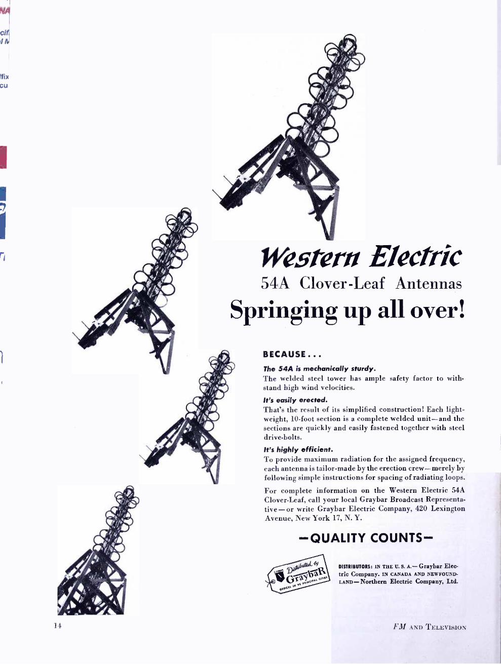
Wesrern Electric 54A Clover -Leaf Antennas
Springing up all over!
I1
BECAUSE... The 54A is mechanically sturdy. The welded steel tower has ample safety factor to with- stand high wind velocities.
It's easily erected. That's the result of its simplified construction! Each light- weight, 10 -foot section is a complete welded unit -and the sections are quickly and easily fastened together with steel drive -bolts.
It's highly efficient. To provide maximum radiation for the assigned frequency, each antenna is tailor -made by the erection crew - merely by following simple instructions for spacing of radiating loops.
For complete information on the Western Electric 54A Clover -Leaf, call your local Graybar Broadcast Representa- tive - or write Graybar Electric Company, 420 Lexington Avenue, New York 17, N. Y.
-QUALITY COUNTS-
DISTRIBUTORS: IN THE U. S. A.- Graybar Elec- tric Company. IN CANADA AND NEWFOUND-
LAND- Northern Electric Company, Ltd.
FM AND Tb:LH:V1ti1ON
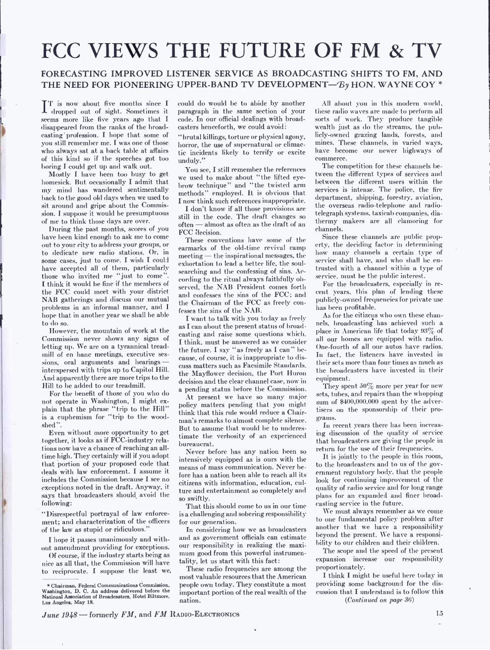
FCC VIEWS THE FUTURE OF FM & TV FORECASTING IMPROVED LISTENER SERVICE AS BROADCASTING SHIFTS TO FM, AND THE NEED FOR PIONEERING UPPER -BAND TV DEVELOPMENT -r13y HON. WAYNE COY
IT is now about five months since I dropped out of sight. Sometimes it
seems more like five years ago that I disappeared from the ranks of the broad- casting ' profession. I hope that some of you still remember me. I was one of those who always sat at a back table at affairs of this kind so if the speeches got too boring I could get up and walk out.
Mostly I have been too busy to get homesick. But occasionally I admit that my mind has wandered sentimentally back to the good old days when we used to sit around and gripe about the Commis- sion. I suppose it would be presumptuous of me to think those days are over.
During the past months, scores of you have been kind enough to ask me to come out to your city to address your groups, or to dedicate new radio stations. Or, in some cases, just to come. I wish I could have accepted all of them, particularly those who invited me "just to come ". I think it would be fine if the members of the FCC could meet with your district NAB gatherings and discuss our mutual problems in an informal manner, and I hope that in another year we shall be able to do so.
However, the mountain of work at the Commission never shows any signs of letting up. We are on a tyrannical tread- mill of en banc meetings, executive ses- sions, oral arguments and hearings - interspersed with trips up to Capitol Hill. And apparently there are more trips to the Hill to be added to our treadmill.
For the benefit of those of you who do not operate in Washington, I might ex- plain that the phrase "trip to the Hill" is a euphemism for "trip to the wood- shed".
Even without more opportunity to get together, it looks as if FCC -industry rela- tions now have a chance of reaching an all - time high. They certainly will if you adopt that portion of your proposed code that deals with law enforcement. I assume it includes the Commission because I see no exceptions noted in the draft. Anyway, it says that broadcasters should avoid the following:
"Disrespectful portrayal of law enforce- ment; and characterization of the officers of the law as stupid or ridiculous."
I hope it passes unanimously and with- out amendment providing for exceptions.
Of course, if the industry starts being as nice as all that, the Commission will have to reciprocate. I suppose the least we.
* Chairman, Federal Communications Commission, Washington, D. C. An address delivered before the National Association of Broadcasters, Hotel Biltmore, Los Angeles, May 18.
could do would be to abide by another paragraph in the same section of your code. In our official dealings with broad- casters henceforth, we could avoid: " brutal killings, torture or physical agony, horror, the use of supernatural or climac- tic incidents likely to terrify or excite unduly."
You see, I still remember the references we used to make about "the lifted eye- brow technique" and "the twisted arm methods" employed. It is obvious that I now think such references inappropriate.
I don't know if all those provisions are still in the code. The draft changes so often - almost as often as the draft of an FCC decision.
These conventions have some of the earmarks of the old -time revival camp meeting - the inspirational messages, the exhortation to lead a better life, the soul - searching and the confessing of sins. Ac- cording to the ritual always faithfully ob- served, the NAB President comes forth and confesses the sins of the FCC; and the Chairman of the FCC as freely con- fesses the sins of the NAB.
I want to talk with you today as freely as I can about the present status of broad- casting and raise some questions which, I think, must be answered as we consider the future. I say "as freely as I can" be- cause, of course, it is inappropriate to dis- cuss matters such as Facsimile Standards, the Mayflower decision, the Port Huron decision and the clear channel case, now in a pending status before the Commission.
At present we have so many major policy matters pending that you might think that this rule would reduce a Chair- man's remarks to almost complete silence. But to assume that would be to underes- timate the verbosity of an experienced bureaucrat.
Never before has any nation been so intensively equipped as is ours with the means of mass communication. Never be- fore has a nation been able to reach all its citizens with information, education, cul- ture and entertainment so completely and so swiftly.
That this should come to us in our time is a challenging and sobering responsibility for our generation.
In considering how we as broadcasters and as government officials can estimate our responsibility in realizing the maxi- mum good from this powerful instrumen- tality, let us start with this fact:
These radio frequencies are among the most valuable resources that the American people own today. They constitute a most important portion of the real wealth of the nation.
June 1948 - formerly FM, and FM RADIO- ELECTRONICS
All about you in this modern world, these radio waves are made to perform all sorts of work. They produce tangible wealth just as do the streams, the pub- licly -owned grazing lands, forests, and mines. These channels, in varied ways, have become our newer highways of commerce.
The competition for these channels be- tween the different types of services and between the different users within the services is intense. The police, the fire department, shipping, forestry, aviation, the overseas radio- telephone and radio- telegraph systems, taxicab companies, dia- thermy makers are all clamoring for channels.
Since these channels are public prop- erty, the deciding factor in determining how many channels a certain type of service shall have, and who shall be en- trusted with a channel within a type of service, must be the public interest.
For the broadcasters, especially in re- cent years, this plan of lending these publicly -owned frequencies for private use has been profitable.
As for the citizens who own these chan- nels, broadcasting has achieved such a place in American life that today 93% of all our homes are equipped with radio. One -fourth of all our autos have radios. In fact, the listeners have invested in their sets more than four times as much as the broadcasters have invested in their equipment.
They spent 50% more per year for new sets, tubes, and repairs than the whopping sum of $400,000,000 spent by the adver- tisers on the sponsorship of their pro - grains.
In recent years there has been increas- ing discussion of the quality of service that broadcasters are giving the people in return for the use of their frequencies.
It is jointly to the people in this room, to the broadcasters and to us of the gov- ernment regulatory body, that the people look for continuing improvement of the quality of radio service and for long range plans for an expanded and finer broad- casting service in the future.
We must always remember as we come to one fundamental policy problem after another that we have a responsibility beyond the present. We have a responsi- bility to our children and their children.
The scope and the speed of the present expansion increase our responsibility proportionately.
I think I might be useful here today in providing some background for the dis- cussion that I understand is to follow this
(Continued on page 36)
1,5

FIG. 1. In the home of Mr. A. H. Sherin, Summit, N. J., this Scerbo cabinet com- pletely disguises the Brociner- Klipsch speaker system within. It is operated by the radio -phonograph installation shown on the front cover of this issue. The FM- AM tuner is a Collins Audio design
DESIGNS FOR NTUSICAL ENJOYMENT FM HAS CREATED A DEMAND FOR AUDIO QUALITY. NOISE- SUPPRESSOR HAS REMOVED NEEDLE -SCRATCH. RESULT: SOME HOMES HAVE FINE MUSIC -By MILTON B. SLEEPER
THERE is a world of sound, common sense thinking for radio dealers and
manufacturers in the words of George Nelson, the very successful designer, who likes to let off steam once in a while in such a manner as this:
"When the new Studebaker came out, it aroused considerable interest because it was the only postwar car that showed any freshness of design. I had occasion to mention this to a General Motors vice - president shortly afterward, and was told that General Motors has no interest in radical design changes. If we assume that the competence of the designers working for General Motors and for Studebaker is roughly the same, then we are pushed to the conclusion that the basic instrument in the redesign was neither talent nor engineering, but company policy."
This situation does not prevail in the automobile industry alone. Mr. Nelson continues: "Take the table radio as a case in point. Over 12,000,000 of these units were produced in 1947, and the vast majority differ from each other only superficially. The standard solution is a decorative plastic case with certain limited variations in dials, knobs, and grilles, and the design level is several notches below mediocrity."
The "standard solution" has also been decidedly limited as to price. Right here we come to a very significant situa- tion that is not yet recognized by radio manufacturers. Let's get at it in this way:
16
The $89.50 mantle radio of 1930, which became the current $24.95 AM table model, was responsible for putting radio reception in something like 95% of the American homes. Today, in metropolitan areas, these sets are adequate for bringing in news reports, and on music they satisfy those people who, in public places, put nickels in juke boxes. Outside the very limited primary service areas of AM sta- tions, interference due to crowding of the frequency band has rendered these models almost worthless in the evening.
However, attendance records at the con- certs show that there is a greater demand for musical entertainment than ever be- fore. That demand is not being met by cheap AM sets because they simply are not musical instruments.
Suppose all the piano manufacturers put national advertising campaigns be- hind designs priced at $175, and offered them as giving "concert -hall tone from this miniature piano ", or "music of the immortals from a piano a little girl can lift." How, then, could they sell real pianos at $1,550 up?
Well, that's exactly what radio set manufacturers are doing today. Here are quotations from recent advertisements in Life and The Saturday Evening Post by leading radio manufacturers:
"In beauty, .performance and value, here's another record -breaking triumph from the - laboratories." ($29.95 table model)
"New materials, better engineering, finer reception and greater value." ($19.95 table model)
"There is constant testing and re -test- ing - proving and improving - to assure the Reception - Perfection - the Studio Tone in Your Home- for which - has become so widely celebrated." (miniature plastic model)
"Here's the rounded, resonant tone of a fine console plus the compact conveni- ence of a table radio!" (plastic and wooden table models)
"The greatest improvement in record playing since the invention of the phono- graph . . . bringing a new high in record listening pleasure." ($99.95 console radio - phonograph)
These statements are not only bad ad- vertising because they imply that the best in radio sets can be bought for $19.95 to $99.95, but because, by the most charitable judgment, they are utter ba- loney. Measured against the facts, they are downright lies.
Other Side of the Picture: Fortunately for people who want truth- ful reproduction of what good music there is on the air, and of the good recorded music, a few manufacturers - all too few
. - are producing high quality FM -AM- phonograph combinations. Unfortunately for them, their distribution is largely con- centrated in metropolitan areas, and their sales have been hurt by television to the
FM AND TELEVISION

extent that their dealers feature what people ask for.
Now, let's go back to another signifi- cant remark by George Nelson. He puts it this way: "In a market where manu- facturers compete by imitating each other's designs, the safest policy, in a business sense, is often a radical one."
Until the advent of Frequency Modula- tion, there was no source from which perfect reproduction could be obtained. With FM as a source of fine music, there was a reason to develop high -fidelity amplifiers and speakers. But because there was, and still is a limited amount of good music available on the air, records were needed, too. Since records have their audio limitations, particularly in the matter of
needle- scratch, improved audio systems only emphasized their short -comings. That paved the way for Hermon Scott's dynamic noise suppressor. Then came the 15,000 -cycle FM network operations, and the duplication of AM network programs on FM. The latter, in most cases, are still limited by 5,000 -cycle lines, but it is amaz- ing to hear the improvemént, outside the areas of primary AM coverage, when even 5,000 -cycle programs are heard with FM's background of silence.
So, while the set manufacturers, still plodding along behind their $24.95 ban- ners, are busy imitating one another, the custom set- builders are selling musical en- tertainment. What's more, they are giving their customers the postwar improve- ments that the big companies promised but have not delivered.
Good Installations Are Expensive:
The very best in FM reception and rec- ord playing costs a lot of money. How much? Well, almost as much as an average piano. But a piano is silent except when someone chooses to play on it, and fre- quently the people who have to listen like the piano better when it isn't being used. The supply of artists is so limited in most homes!
The somewhat- less -expensive FM re- ceiver, with a phonograph and noise sup- pressor, and a good audio system, make the music of the great artists available at the turn of a switch.
No one questions the worth of a piano at $1,550 to $3,000. Now the custom set -builders are discovering that they can give a far greater value of enjoyment at $750 to $2,000!
To the $19.95 -minded radio industry, this is, indeed, a radical idea, but it's proving highly profitable to those who are promoting it.
Solution of the Furniture Problem: The only advantage offered by the ta- ble model is the ease with which it can he kept out of sight. The large cabinets re- quired for the over -size dimensions of high- quality equipment are always a problem. Even if a room is big enough to
take the cabinet, there is sure to be some- thing wrong with the appearance of any standard design.
This poses no problem to the custom set- builder. He has three outs. He can 1)
build a special cabinet, or two cabinets if the speaker is to be housed separately, 2) rework an existing piece of furniture to take the equipment, or :3) put the equipment in sonic permanent, functional piece, such as a wall closet, bookcase, or window seat.
Examples of Custom Installations: The accompanying photographs show typ- ical examples of the custom set -builders' art. The front cover shows one very in- teresting FM -AM- phonograph installa- tion, operated in conjunction with a separate speaker, Fig. 1. This is in the home of A. H. Sherin, at Summit, New Jersey. In every last detail. it was planned to meet the owner's specifications of "nothing less than the best."
The following equipment is used in this installation: FM -AM Tuner: Collins Audio Products Amplifier & Noise Suppressor: H. H. Scott Expander: Fisher Radio Speaker: Brociner- Klipsch Record Changer: Garrard Tone Arm: Pickering diamond -point Cabinets: Scerho Mfg. Company
The speaker, manufactured by Bro-
einer, is a particularly interesting example of eonst.ruction, because it completely Bide. the l'lip.eli -Iype Iaflle.
Fig. 2 shmv-s a different type of in- .l:Illatiotn, this one in the home of Dr. I{:tn v Bigelow Of ('i,liasset and Boston. .\ Highly -prüed and Hne breakfront was carefully altered to take the equipment. The speaker, located nt the opposite end of the room, is an .\Ile(.- Lansing type 604, in a type (;u.Ì ealiinet.
I)r. Barry's inslallalioii H
the following units: l'NI -,\ NI 'l'inter: Browning Laboratories Amplifier & Noise Suppressor: II. H. Scott Record ('hanger: Garrard Speaker: Alter Lansing
Elliot Bicknell, of Wahan, Mass., is a particularly ardent FM listener. His in- stallation is shown in Fig. 3. I -le reports reception of 36 stations. including rea- sonably consistent signals front Alpine, at a distance of 190 miles.
The cabinet at the right carries the compass rose and control buttons for a 3- element rotary antenna, an A11I tuner, a 2 -hand FM tuner, and a power ampli- fier. The phonograph turntable, speaker. and record files are built into the window seat. Mr. Bicknell lists the units as follows: Antenna: Workshop :Associates AM Tuner: McMurdo Silver VI FM Tuner: Radio Engineering Labs. Amplifier: Brook Electronics
made up of
FIG. 2. Dr. Barry Bigelow's installation, Cohasset, Mass., has an Altee Lansing speaker
ri
i
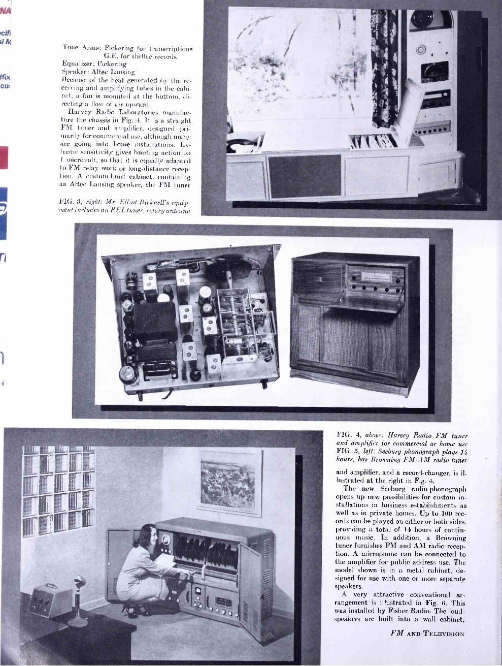
Tone Arms: Pickering for transcriptions G.E. for shellac records
Equalizer: Pickering Speaker: Altec Lansing Because of the heat generated by the re- ceiving and amplifying tubes in the cabi- net, a fan is mounted at the bottom, di- recting a flow of air upward.
Harvey Radio Laboratories manufac- ture the chassis in Fig. 4. It is a straight FM tuner and amplifier. designed pri- marily for commercial use, although many are going into home installations. Ex- treme sensitivity gives limiting action on 1 microvolt, so that it is equally adapted to FM relay work or long -distance recep- tion. A custom -built cabinet, containing an Altec Lansing speaker, the FM tuner
FIG. 3, right: Mr. Elliot Bicknell's equip- ment includes an REL tuner, rotary antenna
FIG. 4, above: Harvey Radio FM tuner and amplifier for commercial or home use FIG. 5, left: Seeburg phonograph plays 14 hours, has Browning FM -AM radio tuner
and amplifier, and a record -changer, is il- lustrated at the right in Fig. 4.
The new Seeburg radio -phonograph opens up new possibilities for custom in- stallations in business establishments as well as in private homes. Up to 100 rec- ords can be played on either or both sides, providing a total of 14 hours of contin- uous music. In addition, a Browning tuner furnishes FM and AM radio recep- tion. A microphone can be connected to the amplifier for public address use. The model shown is in a metal cabinet, de- signed for use with one or more separate speakers.
A very attractive conventional ar- rangement is illustrated in Fig. 6. This was installed by Fisher Radio. The loud- speakers are built into a wall cabinet,
FM AND TELEVISION
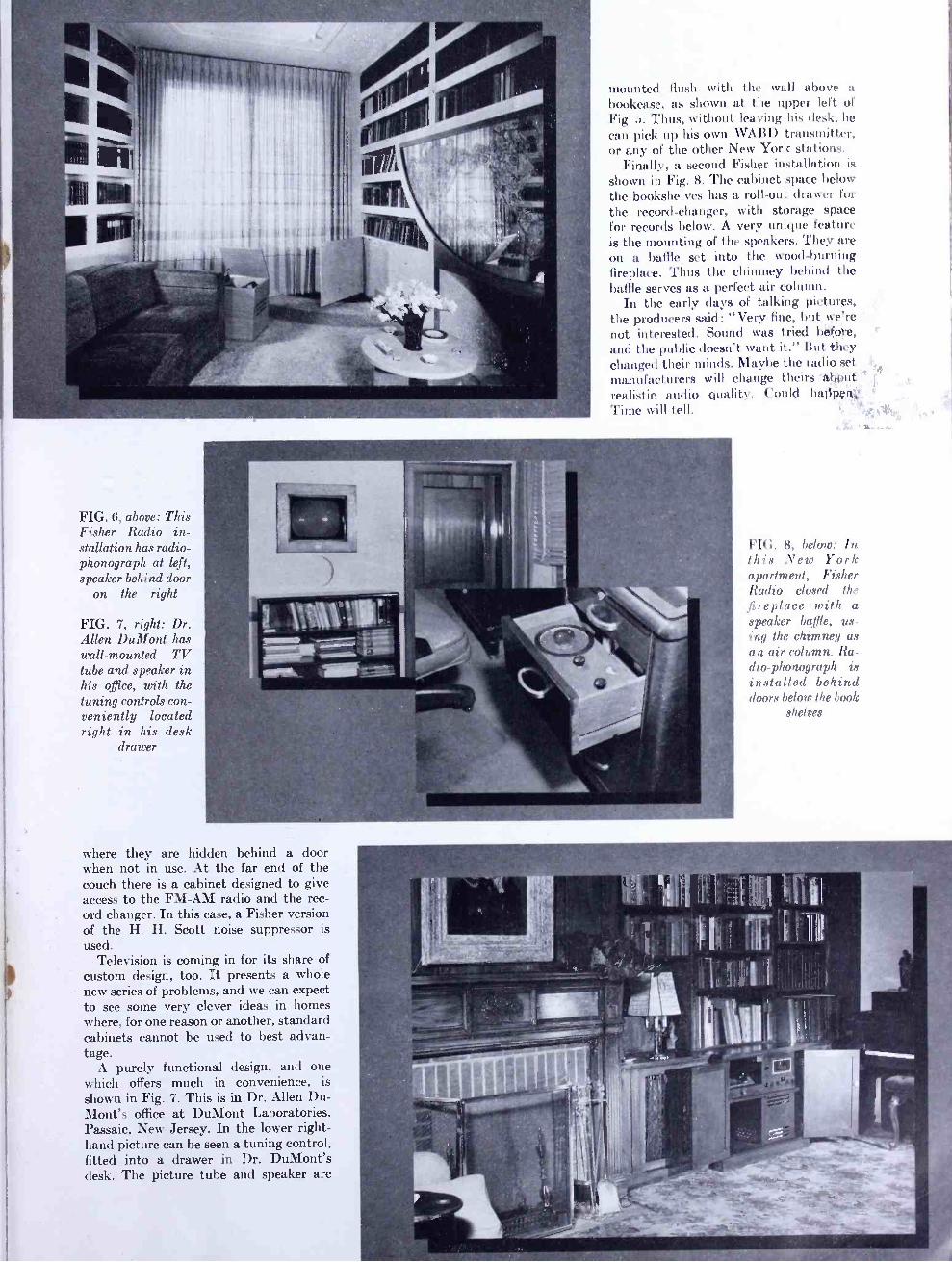
mounted flush with the wall above a bookcase, as shown at the upper left of Fig. 5. Thus, without leaving his disk, he can pick up his own WA131) tr.uisniittcr, or any of the other New York t ions.
Finally, a second Fisher i II ion is
shown in Fig. 8. The cabinet space below the bookshelves has a roll -out drawer for the record -changer, with storage space for records below. A very unique feature is the mounting of the speakers. They are on a baffle set into the wood- burning fireplace. Thus the chimney behind the baffle serves as a perfect air column.
In the early days of talking pictures, the producers said: "Very fine, but we're not interested. Sound was tried before, and the public doesn't want it." But they changed their minds. Maybe the radio set manufacturers will change theirs -44b tit realistic audio quality. Could ha13pçtx
Time will tell _
FIG. 6, above: This Fisher Radio in- stallation has radio - phonograph at left, speaker behind door
on the right
FIG. 7, right: Dr. Allen DuMont has wall- mounted TV tube and speaker in his office, with the tuning controls con- veniently located right in his desk
drawer
FIG. 8, below: In this New York apartment. Fisher Radio closed the fireplace with a speaker Ladle, us- ing the chimney as an air column. Ra- il i 0-phonograph is installed behind doors below the boot:
shelves
where they are hidden behind a door when not in use. At the far end of the couch there is a cabinet designed to give access to the FM -AM radio and the rec- ord changer. In this case, a Fisher version of the H. H. Scott noise suppressor is used.
Television is coming in for its share of custom design, too. It presents a whole new series of problems, and we can expect to see some very clever ideas in homes where, for one reason or another, standard cabinets cannot be used to best advan- tage.
A purely functional design, and one which offers much in convenience, is
shown in Fig. 7. This is in Dr. Allen Du- Mont's office at DuMont Laboratories, Passaic, New Jersey. In the lower right - hand picture can be seen a tuning control, fitted into a drawer in Dr. DuMont's desk. The picture tube and speaker are
cifl M
REMOTE PICKUP RELAYS ON- THE -SPOT COVERAGE OF DISASTERS AND EMERGENCIES IS MADE POSSIBLE BY FM ON 152 -162 MC -By FREDERICK T. BUDELMAN
ONE of the most important
public- service fea- tures of radio broad- casting has been built around what program directors call "special events". This very broad term covers all spontaneous sit- uations which range from rear -platform speeches by Govern- ment officials to news of fires, floods, and
other emergencies when minutes may mean saving lives and property.
By their nature, these events seldom occur where wire lines are available for studio connections. Therefore, mobile units must be employed. This calls for equipment and frequency channels capa- ble of giving solid service from the scene of action, wherever it takes place.
Background of Present Setup: The final frequency allocations plan
for the non -governmental radio services released by the FCC on May 17, 1945, provided for new channels between 152 and 162 mc. for remote pickup relay ser- vices. This cancelled the previous assign- ment of 16 channels (12 non -shared and 4 shared) in the band from 30 to 40 mc. for relay broadcasting, but provided twelve 60 -mc. channels between 152 and 162 mc. to be shared with the motion -picture, geo- physical, and forestry -conservation cate- gories; also, twenty -four 25 -kc. channels between 25 and 28 mc., to be shared with the geophysical service.
Accordingly, after the new channels were assigned in the 15e- to 162 -mc. band, Link Radio undertook the develop- ment of FM equipment for this purpose, in order to provide a higher degree of audio quality and a lower level of noise than had been available previously.
The first wide -scale tests and demon- strations of land -mobile equipment oper- ating on 152 to 162 mc. were conducted by Link engineers ! in February, 1946, under the extremely adverse conditions prevail- ing in the mid -Manhattan area of New York City. The highly satisfactory re- sults, with solid coverage even when the mobile transmitter was between high steel- framed buildings and in highway
* Vice President and Chief Engineer, Link Radio Corporation, 125 W. 17th Street, New York 11.
I See FM AND TELEVISION, May, 1945, for com- plete table of frequency allocations.
20
underpasses, indicated that the new fre- quency range would be ideal for remote pickup operations. Later, several of the large networks and a number of independ- ent companies conducted further tests. Their results were superior to those ob- tained with any previous equipment on 25 to 28 mc. or 30 to 40 mc.
Pickup Equipment for 152 -162 Mc.: It should be pointed out that the de-
velopment of the units now in use was based on previous experience with both civilian and military FM equipment.
The basic unit is a 50 -watt mobile FM transmitter for 152 to 162 mc., operated by a self- contained, 12 -volt dynamotor. The 12 -volt primary power source was chosen in preference to 6 volts because of the relatively large power consumption during the long periods of operation en- countered in broadcast work. Frequency response is uniform from 70 to 7,000 cycles, with distortion and noise levels appropriately low. A companion power supply operating from 110 volts, 60 cycles can be substituted in a few seconds.
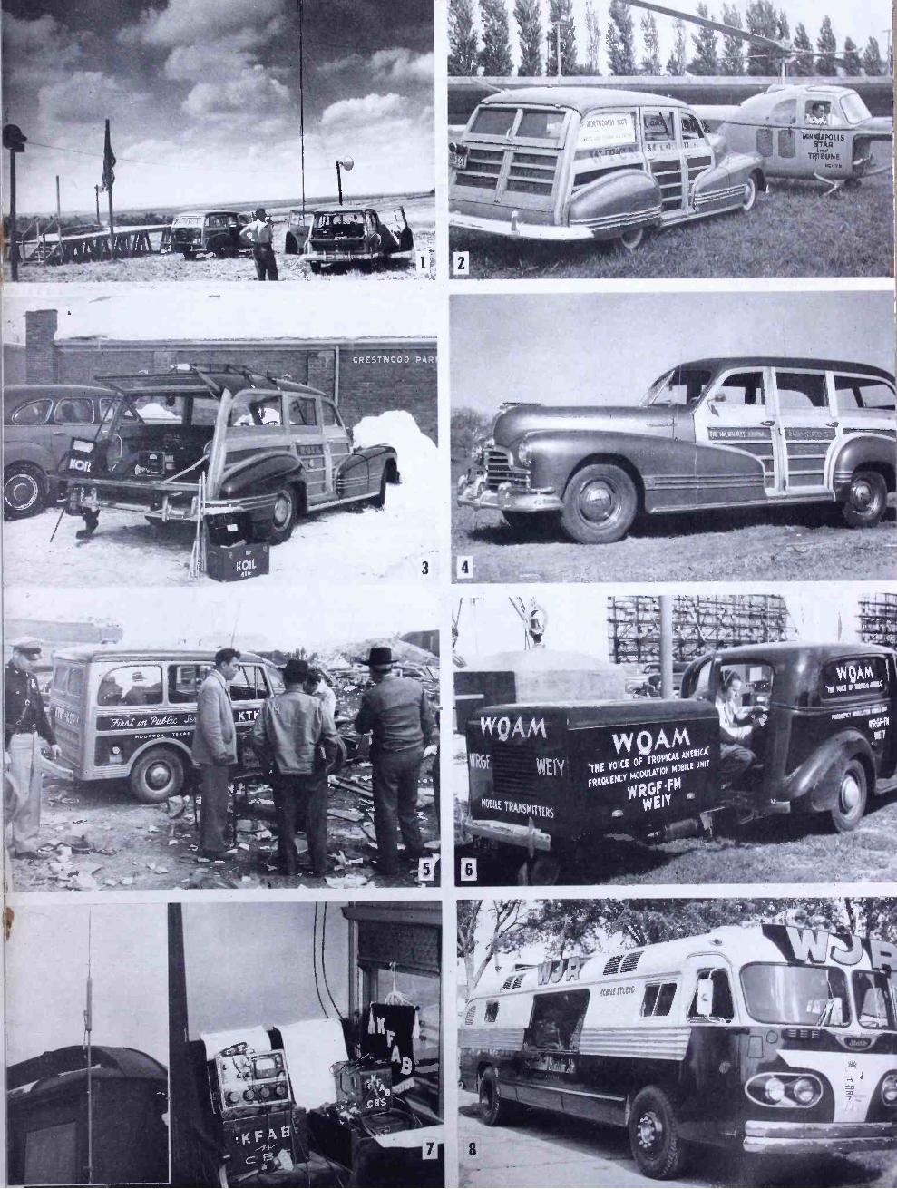
The accompanying illustrations show the use of quarter -wave roof -top antennas, as in Figs. 2 and 4, or coaxial antennas and collapsible directional arrays, as in Fig. 1, for long hauls.
The program receiver is a rack - mounted, crystal -controlled FM unit, capable of operating on signals as low as 1 microvolt. Various types of directional or non -directional receiving antennas are used. Most common is the vertically - polarized beacon antenna, with a power gain of 4, and a non -directional pattern. At WTCN, Minneapolis, for example, the relay receiver antenna is mounted on top of the FM antenna illustrated here.
FCC Proposes Deletion of Channels: Now, searching for more channels for
the various communications services, the FCC seeks in its proposal of May 5, 1948, to cancel the remote pickup channels in the 152- to 162 -mc. band, and to shift the present assignments to new frequencies between 450 and 460 mc.
The immediate effect of this proposal was to interrupt all plans for adding mo- bile pickup relay units at stations which were getting ready to install this equip- ment. Even though the FCC allows those already licensed in the 152- to 162 -mc. band to continue for several years, no
2 Reported in "Selective Calling in New York on 157 Mc." by Milton B. Sleeper, FM AND TELEVISION, February, 1946.
new installations will be made on that band since they cannot be used for a time sufficient to amortize the cost.
And it is doubtful if manufacturers will undertake the development and field - testing of new designs for 450 to 460 mc., since they have hardly had time to charge off the development and tool costs of the 152- to 162 -mc. units.
That, from the public- service angle, is a bad situation, since the most valuable use of pickup remote equipment is under conditions of emergency when lives and property are at stake.
Problems on 450 to 460 Mc.: There is a certainty that equivalent
service cannot be rendered on 450 to 460 mc. Some work has been done with these frequencies on point -to -point communi- cation, but these installations operate un- der ideal conditions. Tests made with mobile equipment on 450 to 460 mc. have demonstrated that great difficulty will be encountered in obtaining coverage be-
_ yond optical paths.
What the Broadcasters Need: Under circumstances that permit the
use of fixed remote pickup transmitters, operation over reasonable distances should be possible on 450 to 460 mc. Where any congestion exists on the lower frequencies now in use, some advantage might be gained by such a shift.
However, the importance of emergency services now being rendered on 152 to 162 mc. by pickup relays is such that public interest, convenience, and necessity call for encouraging the expansion of this service among stations not already equipped.
It is possible that something entirely new and useful may come from opening up channels on 450 to 460 mc.
But it is imperative, in the interest of the public, that the 152- to 162 -mc. channels be continued for pickup relaying. Only in this way can more stations be encouraged to operate mobile transmit- ters for on -the -spot coverage of emergen- cies, and with the assurance of getting dependable signals at the studio. When minutes count, there is no time to wrestle with propagation problems on 450 to 460 mc.
Right: Link remote relays operated by: 1) KFAB Omaha, 2) WTCN Minneapolis, 3) KOIL Omaha, 4) WTMJ Milwaukee, 5) KTHT Houston, 6) WQAM Miami. 7) KFAB's Friendship Train installation,
8) WJAR Detroit
FM AND TELEVISION
3 LI,
-
WQAM
WRGf WEIY
WQ AM 'THE VOICE OF TROPICAL EÑ FREQUENCY
MODULATION M UNIT
w fM
wy
t

ffix
cu:
SPOT NEWS NOTES Miss Frieda B. Hennock:
lurk City Lawyer and active rnem- hcr of the Democratic party is the first woman to be nominated to the FCC. She is to fill the vacancy created by the expira- tion of Commissioner Durr's term on June :30.
Facsimile over WGHF: Capt. Finch's New York City station lias been authorized by the FCC to transmit commercial facsimile. There will be four 15- minute periods between 7:00 p.ni. and midnight. Finch announcement says that product ion has been started on the initial run of 5000 Home recorders.
William B. Lodge: CBS director of engineering since 1944 and a nmeniher of the technical staff since
ij 1931, has been named vice president in charge of general engineering.
Coming, Coming, Here: Full -page newspaper announcement from (Quincy, Ill., carries the headline: \1" FAD - FbI was 4,(1(10 watts . . . was 16,000 watts . . . is NOW 53,000 watts effective radiation.
i
i
Source of Distortion: Frank Lyman, president of Harvey Radio Laboratories, suggests that one source of audio distortion contributed by FM tun- ing circuits lies in the modulation of the oscillator by poor regulation of the plate - voltage supply. It appears that FM re- ceiver designs should be checked with great care for possible trouble from that source.
Upper -Band TV Station: R('.1 expects to start experimental opera- tion of an upper -band TV transmitter at Washington, D. C., some time in Septem- ber. Litial plan is to operate on 504 to 510 me. This probably means temporary use of standard equipment for purposes of check- ing propagation. Transmitter will deliver effective radiation up to 25 kw. Later, no doubt, channel will be widened to increase number of lines per inch, since the upper band will allow increased definition.
FM Automobile Sets: B..1. Schwarz. chief engineer of G.M.'s Defeo Radio Division, coinnienting on the reference to FM automobile sets in our April issue: "Recent tests in the Chicago area, principally, indicates many serious problems to be solved before a satisfactory FM automobile broadcast receiver and satisfactory reception of FM broadcast programs in an automobile are arrived at." This seems surprising because, hack in
22
ITEMS AND COMMENTS, PERSONAL AND OTHER- WISE, ABOUT MANUFACTURING, BROADCASTING, COMMUNICATIONS, AND TELEVISION ACTIVITIES
1941, Paul do A l ars was getting FM recep- tion in his car, far superior to anything we have ever heard on AM, from a rebuilt General Electric tuner and an ordinary whip antenna mounted on the rear bumper.
10 -KW. FM Transmitters: According to an announcement from Western Electric, this company has de- livered forty -five 10 -kw. FM transmitters, of which more than twenty -three were on the air the first of May.
Police and Fire Systems: Baltimore is setting up coordinated police and fire communications systems which will comprise 215 mobile units with two 250-watt fixed transmitters. Mobile units will be installed on police cars, fire ap- paratus, fire boats, and harbor patrol boats. System will operate over 300 square miles. Federal Telephone and Radio Cor- poration is supplying the equipment: The installation is being made under the super- vision of Captain William Taylor of the Baltimore police, with the cooperation of Kann- Elbert Electronics Co.
Price Reductions: Westinghouse lias announced price reduc- tions on five FM -AM receiver models, ranging from $20 to $125. Maximum re- duction applies to the $625. phonograph combination which now lists at $499.95.
FCC Chairman Coy: Addressing the NAB at Los Angeles, May 18: "The full, free, rapid exchange of in- formation and opinions, as between the Government and the citizens, and as be- tween the citizens themselves, .is not es- sential in a totalitarian state. - But it is an imperative to the functioning of a democracy. - I know of no responsible person in the Government, including members and staff of the FCC, who favors government operations of broad- casting."
FM -TV Station Score: Status of FM -TV broadcasting on June 1
shows the following saves: TV FM
Operating 24 537 Authorized 72 499 Pending 250 81
TO'T'AL 346 1117 There are also 20 educational FM stations on the air.
FM Reception on Mt. Washington: Paul Gerhard, reporting frone Yankee Network's station: "We can time in 26
high -band stations on a prewar Hallicrafter S -27." Surprisingly, he adds: "Not one of these stations carries NBC programs."
Five Years Ago: Here's an echo from the dim but not -so- distant past: James Lawrence Fly, then FCC Chairman, addressing the 1943 RMA Convention: "The sad experience of prior years resulted in more careful planning in the FM and television bands." Neverthe- less, Paul Porter overhauled them in 1945!
Old Fashioned: Dr. Charles B. Jolliffe, testifying before the House Interstate Committee on Inter- state and Foreign Commerce, March 31: "The significance of this [RCA] pioneer- ing work [on frequencies above 30 mc.] can best be understood when it is realized that two of the principal advantages of high frequency or FM broadcasting, viz., high fidelity and freedom from natural static, are derived from the use of these higher radio frequencies, and not from the type of modulation employed." This view seems a little old fashioned. One company, with the same idea, spent some $34 million in a postwar effort to develop AM railroad radio equipment, only to shift to FM in order to eliminate static interference. As for high -fidelity broad- casting, that can be enjoyed only if static is eliminated.
Largest LCC System: U- Dryvit Auto Rental Company, Cam- bridge, Mass., has been authorized by FCC to install limited common carrier systems in 21 cities throughout New England and New York State. Project calls for 1915 mobile units in rented and in privately -owned cars and trucks. Philco equipment will be used throughout. U- Dryvit is already operating an ex- tensive LCC service in Boston.
Continental Network: Will report the Republican and Demo- cratic conventions over 25 stations in a population area of more than 10 million. Program will start each day when the meetings open, and will continue until last gavel falls at night. Commentators will include Joseph McCaffrey, John Corcoran, and Paul Green.
KOAD Omaha: Now claims to be most powerful Missouri Valley FM station. With a new 10 -kw. G.E. transmitter on an 8.bay Federal antenna, effective radiated power is 70 kw. Full authorized power of 380 kw. will be used as soon as final amplifier is de- livered.
FM AND TELEVISION
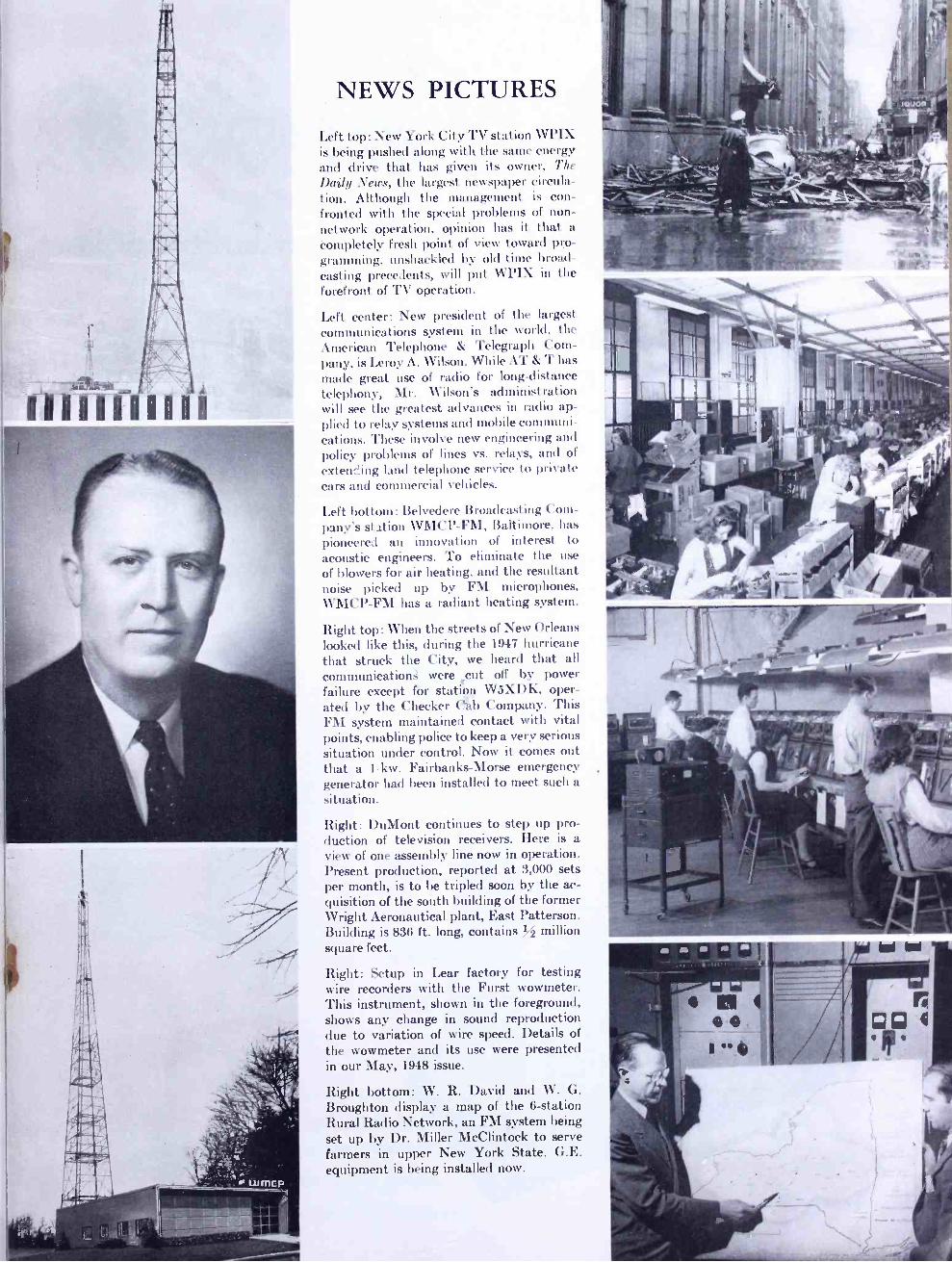
iiii-i diií
NEWS PICTURES
Left top: New York City TV station Wl'IX is being pushed along with the same energy and drive that has given its owner, The
Daily News, the largest newspaper circula- tion. Although the management is con- fronted with the special problems of non - network operation, opinion has it that a completely fresh point of view toward pro- gramming, unshackled by old time broad- casting precedents, will put WPI.X in the forefront of TV operation.
Left center: New president of the largest communications system in the world, the American Telephone & Telegraph Com- pany, is Leroy A. Wilson. While AT & T ha, made great use of radio for long -distance telephony, Mr. Wilson's administration will see the greatest advances in radio ap- plied to relay systems and mobile communi- cations. These involve new engineering and policy problems of lines vs. relay, and of
extending land telephone service t private cars and commercial vehicles.
Left bottom: Belvedere Broadcasting Com- pany's station WMCP -FM, Baltimore, has pioneered an innovation of interest to acoustic engineers. To eliminate the use
of blowers for air heating, and the resultant noise picked up by FM microphones, WMCP -FM has a radiant heating system.
Right top: When the streets of New Orleans looked like this, during the 1947 hurricane that struck the City, we heard that all
communications were cut off by power failure except for station W5XDK, oper- ated by the Checker CCáb Company. This FM system maintained contact with vital points, enabling police to keep a very serious situation under control. Now it comes out that a 1 -kw. Fairbanks -Morse emergency generator had been installed to meet such a situation.
Right: DuMont continues to step up pro- duction of television receivers. Here is a view of one assembly line now in operation. Present production, reported at 3,000 sets per month, is to be tripled soon by the ac- quisition of the south building of the former Wright Aeronautical plant, East Patterson. Building is 836 ft. long, contains % million square feet.
Right: Setup in Lear factory for testing wire recorders with the Furst wowmeter. This instrument, shown in the foreground, shows any change in sound reproduction due to variation of wire speed. Details of the wowmeter and its use were presented in our May, 1948 issue.
Right bottom: W. R. David and W. G. Broughton display a map of the 6- station Rural Radio Network, an FM system being set up by Dr. Miller McClintock to serve farmers in upper New York State. G.E. equipment is being installed now.
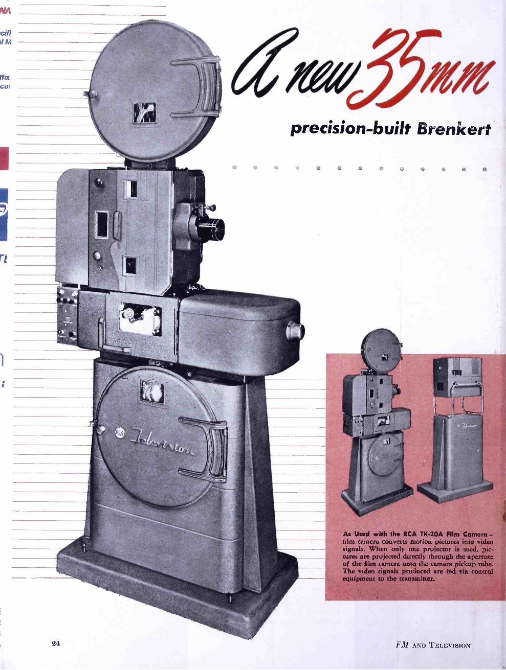
citi !IN
Mx Cu:
precision -built Brenkewt
Mere - film camera converts motion pictures into video signals. When only one projector is used pic- tures are projected directly through the aperture of the film camera onto the camera pickup tube. The video signals produced arc fed via control equipment to the transmitter.
24 FM AND TELEVISION
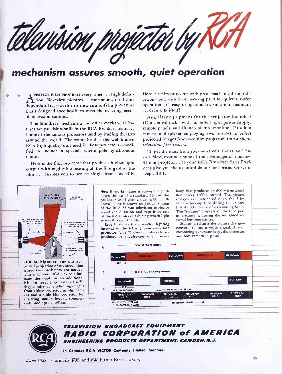
mechanism assures smooth, quiet operation
PERFECT FILM PROGRAM every time ... high-defini- tion, flickerless pictures ... continuous, on- the -air
dependability -with this new sound -film projector that's designed specifically to meet the exacting needs of television stations.
The film -drive mechanism and other mechanical fea-
tures are precision -built in the RCA Brenkert plant ... home of the famous projectors used by leading theatres around the world. The sound -head is the well -known RCA high -quality unit used in these projectors -modi- fied to include a special, salient -pole synchronous motor_
Here is the film projector that produces higher light output with negligible heating of the film gate or the film ... enables You to project single frames as stills.
CCA TK -20A FI M CAMERA
RCA 16mm TELEVISION PROJECTOR OR IC
55mm PROJECTOR
MIRROR
FACE OF CAMERA TUBE
RCA 35/Am TELEVISION PROJECTOR OR RCA
Bmin PROJECTOR
' MIRROR
SLIDE PROJECTOR IS MOUNTED EIER!
RCA Multiplexer -for uninter- rupted projection of multireel films where two projectors are needed. This ingenious RCA device elimi- nates the need for an additional film camera. It consists of a V- shaped mirror for reflecting images from either projector to film cam- era and a slide film projector for inserting station breaks, commer- cials, and special effects.
Here is a film projector with great mechanical simplifi- cation -and with fewer moving parts for quieter, easier operation. It's easy to operate. It's simple to maintain ... even oils itself!
Auxiliary equipment for the projector includes: (1) a control rack -with its pulsed light power supply, remote panels, and 10 -inch picture monitor; (2) a film camera multiplexer employing two mirrors to reflect projected images from two film projectors into a single television film camera.
To get the most from your newsreels, shorts, and fea-
ture films, overlook none of the advantages of this new 35 -mm projector. Let your RCA Broadcast Sales Engi- neer give you the technical details and prices. Or write Dept. 38 -F.
How it works -Line A shows the pull - down timing of a standard 35 -mm film projector (no lighting during 90° pull - down). Line B shows pull -down timing of the RCA 35 -mm television projector -and the duration and repetition rate of the short intervals during which light passes through the film.
Line C shows the projector lighting interval of the RCA 35 -mm television projector. The "light -on" intervals are produced by a pulse -controlled camera
A )<-- 360° (1/24 SECOND) _ -r
k- 90°-I
g k -- 288° (1/30 SECOND)
C
lamp that produces an 800 -microsecond flash every 1 /60th second. The picture images are projected onto the film camera pick -up tube during the retrace (blanking) interval of its scanning beam. The "storage" property of the tube per- mits scanning during the unlighted in- terval between flashes.
Scanning releases the picture charge - converts it into a video signal. A syn- chronizing generator keeps the projector and film camera in phase.
IA-- 122' -,! I. 1/60 SECOND -P4
TELEVISION FIELD
K- 5% LIGHTING INTERVAL
UNLIGHTED INTERVAL IFJLM CAMERA SCAN)
TELEVISION FIELD
TELEVISION FIELD
k--
PULLDOWN
TELEVISION FIELD
TELEVISION FRAME
TELEVISION FIELD
TELEVISION FIELD
TELEVISION BROADCAST EQUIPMENT
RADIO CORPORATION of AMERICA ENÓINEERING PRODUCTS DEPARTMENT, CAMDEN, M.J.
In Canada: RCA VICTOR Company limited, Montreal
June 1948 - formerly FM, and FM RADIO -ELECTRONICS

rE
i
tC
PUTTING WPIX ON THE AIR PRESENTING FIRST -HAND FACTS AND FIGURES, DRAWN FROM THE EXPERIENCE OF BREAKING INTO TELEVISION BROADCASTING IN NEW YORK CITY -By F. M. FLYNN
Wrift regret, keen disappointment, and with some feeling of having
been wronged, we have concluded that we must bear up under an adverse ruling of the Federal Communications Commis- sion on our FM application. The News will not appeal the decision. We are snak- ing an announcement to that effect today. I won't bore you with that announce- ment, but you may be assured that it stakes clear our position regarding the decision.
Now we are free. somewhat against our wish, to concentrate our efforts entirely on television.
Seriously, I think television has now - not tomorrow, but now - all of the es- sentials necessary to become one of the most potent forces in American life. Properly developed, I believe it will re- vitalize Americanism in this Country and it NV-ill provide the added stimulant we so badly need to push forward this expand- ing economy we hear so much about.
The responsibility for developing tele- vision is terrific. You may discount about t)0% of the enthusiastic talk or hokum that is being tossed about regarding tele- vision, and it still adds up to the newest and greatest force for public service in our generat ion.
If it is kept free of propagandists and mealy -mouthed word- twisters who seek to control the channels of mass communica- tion in the world, television will become a new and respected messenger of truth, welcomed in thousands of American homes.
I - don't hold with those who believe television will immediately retake serious inroads on other forms of communication. True, it will be a rival for public accept- ance, at}d competition for the advertising dollar will be keener with television on the scene; but I have a fundamental belief that the American public has a great capacity for absorbing new things and will fit television into its scheine along with radio and other media.
1 l y impression, to date, is that tele- vision is or has been a great thing for everybody except the station operator. The equipment manufacturers are doing a booming business. Set manufacturers, distributors, retailers must be making a fortune. New jobs are created right and left for publicity men. Additional work is becoming available for actors, actresses, all sorts of talent. Even vaudeville is being revived. The film companies are
*President and General Manager, The News, 220 East 42nd Street, Now York City. From an address before the American Television Society, Hotel Astor, New York, April 28, 1048.
offsetting some of their losses by selling the old junk they have had in the files for years and years, at high prices, and everybody is looking for cheap program- ming. Somebody estimated that television will become a $500 million industry. Even the newspapers are profiting, I hope, from advertising of television sets. But I doubt that there is a station on the air today that will do any bragging about its figures on operating television. It's been a great thing for everybody but the station owner.
Now, getting down to WPIX specifi- cally, I have one of the worst sinking feel- ings that you could possibly imagine every time I look at our figures. We have no network, no plans for a network, no definite offers; but I sure think a lot, quite fondly, of how nice it would be to get in on a push -button network operation. We have no manufacturing division. We are not selling any sets. We haven't had any division to absorb the losses, such as all the other big operators. And the news- paper business today isn't so hot that it can take heavy losses and cause its to thrill over operating WPIX.
It's no use to talk to the other New York station owners about costs; they're on the hook and they can't get off. But, during the recent :American Newspaper Publishers Association meetings, I talked with several newspaper publishers who are either under way in television or plan soon to get tender way. I confess I had to laugh like hell when I heard them talk about the estimated costs. I don't know who's telling these people about costs in television but, since there are no secrets in this business, apparently, I see no reason why I shouldn't tell you about a few costs, and you can get some idea of what we and others are doing to try to get television developed.
First, we recognize that all costs have gone up sharply in recent years, but still the difference between our estimated costs and our actual costs are staggering.
When we prepared our application for presentation to the Federal Communica- tions Commission, we estimated our equipment would cost $420,000. The other day I said, "Let's total this up." What is it? Well, it's just a little over $600,000. That's about a 50% increase.
We thought, originally, that we could put our transmitter and some studios within the parapet walls atop The News Building, and we thought we could install a couple of announce studios some place else in the building. That we estimated as $150,000; not bad. Well, we got to actually laying out plans. The parapet wall wouldn't work, there wasn't enough
room. So we have to do the transmitter job on top of the office building, and we have taken over the top of the plant building for studios, work -rooms and other facilities.
We are going to have what I call a two by four studio. We have a film -pro- jection studio, a little announce studio, a lot of dressing rooms, prop rooms, et cetera - all very small. It's really not enough to operate with at all, we're just doing half the job, and the estimated construction (we're getting down, now, pretty close to final bids) is $525,000. That's against $150,000. Theft, if we go on with the second part of the job, it's another $350,000 and we haven't bought any props, scenery, costumes, or anything. That's just the walls with air- condition- ing.
We think we will be on the air pretty soon. I am told we will have on our pay- roll from 150 to 160 employees and the payroll will run at an annual rate of $750,000. We wal not have established an elaborate programming department. Our original estimate for all personnel, including an extensive programming de- partment, was about half that amount - $380, 000.
In the beginning, I was told we could operate television and handle quite a bit of the work in News depart nents. We were going to have the sales handled by our advertising salesmen on The News on some kind of a part -tine arrangement. The auditing work would be done in the Auditing Department, and the promotion and publicity in our Promotion and Pub- licity Department. Now, we have a pub- licity manager (I think-he has an assistant, also) and. even with that, we have a hell of a time getting Ben Gross to give us as much space as he gives NBC. It is obvious that we can't get our auditing done in our regular department. WPIX must have an auditor and he'll probably need an assistant and a secretary. I'm sure, when we wind up, we'll have all these departments up there.
In our presentation to the FCC, which I was looking over recently, we had listed one item of operating costs as "Special Wire Facilities ". Opposite this, on the tabulation of our operating costs were no figures, just the words: Not Known. We should have put "Not Known" op- posite all the rest of them.
So it is easy for me to understand now why some of those who have construction permits for television or who have appli- cations pending are doing what they call (this is something I hay( learned recently) dragging their feet. Possibly these fellows
FM AND TELEVISION
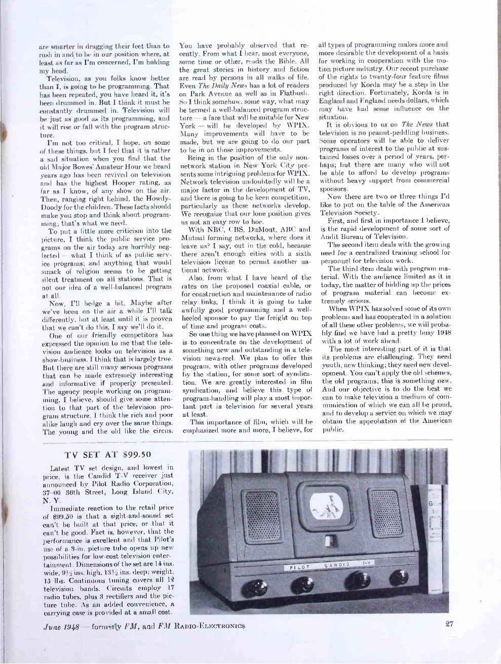
are smarter in dragging their feet than to rush in and to be in our position where, at least as far as I'm concerned, I'm holding my head.
Television, as you folks know better than I, is going to be programming. That has been repeated, you have heard it, it's been drummed in. But I think it must be constantly drummed in. Television will he just as good as its programming, and it will rise or fall with the program struc- ture.
I'm not too critical, I hope, on some of these things, but I feel that it is rather a sad situation when you find that the old Major Bowes' Amateur Hour we heard Years ago has been revived on television and has the highest Hooper rating, as far as I know, of any show on the air. Then, ranging right behind, the Howdy - Doody for the children. These facts should make you stop and think about program- ming; that's what we need.
To put a little more criticism into the picture, I think the public service pro- grams on the air today are horribly neg- lected - what I think of as public serv- ice programs; and anything that would smack of religion seems to be getting silent treatment on all stations. That is
not our idea of a well -balanced program at all.
Now, I'll hedge a bit. Maybe after we've been on the air a while I'll talk differently, but at least until it is proven that we can't do this, I say we'll do it.
One of our friendly competitors has expressed the opinion to me that the tele- vision audience looks on television as a show- business. I think that is largely true. But there are still many serious programs that can be made extremely interesting and informative if properly presented. The agency people working on program- ming, I believe, should give some atten- tion to that part of the television pro- gram structure. I think the rich and poor alike laugh and cry over the same things. The young and the old like the circus.
You have probably observed that re- cently. From what I hear, most everyone, some time or other, reads the Bible. All the great stories in history and fiction are read by persons in all walks of life. Even The Daily News has a lot of readers on Park Avenue as well as in Flatbush. So I think somehow, some way, what may be termed a well -balanced program struc- ture -a fare that will he suitable for New York - will be developed by WPIX. Many improvements will have to be made, but we are going to do our part to be in on those improvements.
Being in the position of the only non - network station in New York City pre- sents some intriguing problems for WPIX. Network television undoubtedly will be a major factor in the development of TV, and there is going to be keen competition, particularly as these networks develop. We recognize that our lone position gives us not an easy row to hoe.
With NBC, CBS, DuMont, ABC and Mutual forming networks, where does it leave us? I say, out in the cold, because there aren't enough cities with a sixth television license to permit another na- tional network.
Also, from what I have heard of the rates on the proposed coaxial cable, or for construction and maintenance of radio relay links, I think it is going to take awfully good programming and a well - heeled sponsor to pay the freight on top of time and program costs.
So one thing we have planned on WPIX is to concentrate on the development of something new and outstanding in a tele- vision news -reel. We plan to offer this program, with other programs developed by the station, for some sort of syndica- tion. We are greatly interested in film syndication, and believe this type of program -handling will play a most impor- tant part in television for several years at least.
This importance of film, which will be emphasized more and more, I believe, for
all types of programming makes more and more desirable the development of a basis for working in cooperation with the mo- tion picture industry. Our recent purchase of the rights to twenty -four feature films produced by Korda may be a step in the right direction. Fortunately, Korda is in England and England needs dollars, which may have had some influence on the situation.
It is obvious to us on The News that television is no peanut -peddling business. Some operators will be able to deliver programs of interest to the public at sus- tained losses over a period of years, per- haps; but there are many who will not be able to afford to develop programs without heavy support from commercial sponsors.
Now there are two or three things I'd like to put on the table of the American Television Society.
First, and first in importance I believe, is the rapid development of some sort of Audit Bureau of Television.
The second item deals with the growing need for a centralized training school for personnel for television work.
The third item deals with program ma- terial. With the audience limited as it is today, the matter of bidding up the prices of program material can become ex- tremely serious.
When WPIX has solved some of its own problems and has cooperated in a solution of all these other problems, we will proba- bly find we have had a pretty busy 1948 with a lot of work ahead.
The most interesting part of it is that its problems are challenging. They need youth, new thinking; they need new devel- opment. You can't apply the old schemes, the old programs; this is something new. And our objective is to do the best we can to make television a medium of com- munication of which we can all be proud, and to develop a service on which we may obtain the approbation of the American public.
TV SET AT $99.50 Latest TV set design, and lowest in
price, is the Candid T -V receiver just announced by Pilot Radio Corporation, 37 -06 36th Street, Long Island City, N. Y.
Immediate reaction to the retail price of $99.50 is that a sight- and -sound set can't be built at that price, or that it can't be good. Fact is, however. that the performance is excellent and that Pilot's Ilse of a 3 -in. picture tube opens up new possibilities for low -cost television enter - tainment. Dimensions of the set are 14 ins. wide, ins. high, 13eí ins. deep; weight. 15 lbs. Continuous tuning covers all 12
television bands. Circuits employ 17
radio tubes, plus 3 rectifiers and the pic- ture tube. As an added convenience, a carrying case is provided at a small cost.
./unc 1948 - forth rly FM, and FM RADIO -ELECTRONICS

1
1
i
AF CIRCUITS EQUALI7ER UTC USES RESONANT CIRCUITS FOR INDEPENDENT HIGH -AND LOW -END BOOSTS-By I. ALLEN MITCHELL*
THE earliest common form of equalizer was the "tone control " employed in
radio receivers to cut off the high fre- quencies. These controls were frequently decried by engineers, on the basis of the fact that the fidelity of the equipment was being reduced through the loss of high frequency performance.
Need for Equalization: Present engineering knowledge justifies the use of more modern types of equaliz- ers, as it has been found from listener - preference tests that a balance between low- and high- frequency response is highly desirable. It can be stated that, for good audio performance, the product of the lower and higher frequency limits of the equipment should equal approximately 500,000. This condition of balanced or equalized response is indicated in Fig. 1. In other words, neither end of the response should be over -extended. A set that is good to only 200 cycles at the low fre- quency end gives the most agreeable performance when the high- frequency response is adjusted to cut off at about 2500 cycles.
CGE- 1 Equalizer: Considerable research and development
work at United Transformer Corporation recently evolved a simple equalizer, Fig. e, which weighs but 2 lbs. and is carried on a panel 2% by 4 ins. The difficulty in the development of an inexpensive equal- izer lay in the fact that it was necessary to use resonant circuits for both high -end and low -end boosts. Fig. 3 shows the effects of boost and droop at both ends.
Simpler construction could be effected by using R -C networks, but the resultant curve of correction they produce is a gradual slope. This does not accomplish what is required. For example, if the unit to be equalized is down 15 db at 5,000 cycles, an R -C equalizer which brings
* Director of Research, United Transformer Cor- poration, 150 Varick Street, New York 13, N. Y.
FIG. 14. Complete amplifier with equalizer
back this 15 db also boosts 6 db at 1,000 cycles. That would be undesirable. Similarly, an equalizer which would effect 15 db correction at 100 cycles and boost 1,000 cycles by 6 db would be undesirable. Figs. 4 through 13 show several different applications where equalization has been successfully employed, using this inex- pensive equalizer to boost highs or lows or to drop highs or lows as required.
Examples of Equalization: It is interesting to note the results of
correction as shown in the accompanying curves. The need for bass boost is gen- erally realized, for the normal drop off of aural response at bass frequencies with reduction in volume level is quite sub- stantial and rapid. By using the 50 -cycle boost of the equalizer as shown in Fig. 4, this low frequency loss is completely compensated.
The falling off of low frequencies in home recordings is intentional. If the low frequencies were not attenuated, the amplitude of recording needle travel would exceed that of the record groove. As a consequence, an equalizer is used during the recording process to cut the low frequencies rapidly, so that, below the cut -off point, the full width of the groove is used, but no more. Fig. 5 illus- trates the use of the equalizer at the 12 db, 100 -cycle boost point to correct this condition.
Lateral transcriptions, as contrasted to home recordings, cut the low frequencies for the reason mentioned above, and also augment the high frequencies, so that these can be attenuated during play- back, with a corresponding reduction in noise level. In other words, the signal -to- noise ratio is considerably greater in the high frequency portion of the recording. To correct for this condition, the equalizer is set at maximum position 50 -cycle boost and 10 db high- frequency droop, as illus- trated in Fig. 6.
The standard vertical transcription is similar to lateral transcriptions, but with a lower crossover frequency, as illus- trated in Fig. 7. The same equalizer settings correct this type of recording admirably.
Loudspeakers, due to electrical and mechanical limitations, fall off at both high and low frequency ends. The curve in Fig. 8 illustrates this condition, though it does not show all the small peaks and dips that characterize loudspeaker re- sponse curves. Using 12 db, 50 -cycle low - boost position and 12 db, 8,000 -cycle high -boost position, the speaker curve shown is substantially equalized. It must
FIG. 2. UTC resonant - circuit equalizer
be remembered, of course, that the low - frequency power -handling capacity of the speaker is not increased through equalization, so that, fully equalized, the maximum level from the speaker without distortion will be reduced.
In addition to loudspeaker frequency- discrimination, RF circuits and other elements in a radio receiver contribute to the drop -off of low and high frequencies. A typical over -all curve of a medium priced receiver is shown in Fig. 9, where the 10 db, 100 -cycle boost and 13 db, 5,000 - cycle boost positions flatten the curve considerably.
High fidelity receivers rarely approach ideal response curves due, in many in- stances, to acoustic conditions in the cabinet, loudspeaker response, and other factors. Fig. 10 shows the 50 -cycle boost and 8,000 -cycle boost .equalizer positions at maximum setting to correct the re- sponse of such a receiver.
Sound -on -film recording has a sharp drop -off at the high end. This is unavoid- able, and is a function of the optical slit. Fig. 11 illustrates a typical curve of this type, which is almost perfectly corrected by using the 8,000- cycle, maximum -boost position of the equalizer.
Telephone lines have both low- and high -end droop. This is a function of the class of line and length. A typical line is illustrated in Fig. 12, with simple correction using 10 db, 100 -cycle boost. and 12 db, 8,000 -cycle boost.
Wire recordings and tape recordings have substantial fall -off at the low end, as a basic characteristic of this type of equipment. The actual curve of both high - and low -end droop is a function not only of the recording head and equipment, but also of the size and type of wire or tape. One curve of this type is shown in Fig. 13, with almost full correction obtained through the use of 15 db, 100 -cycle boost and 7 db, 8,000 -cycle boost.
In addition to the curves shown above and the equalizations which can be effected for such applications, there are many others where equalization is of value. For example, dialogue equalization (low- frequency droop) improves speech intelligibility, and permits higher power levels from speakers used in PA equip- ment.
Circuit Information: All equalizers cause insertion loss in a
FM AND TELEVISION
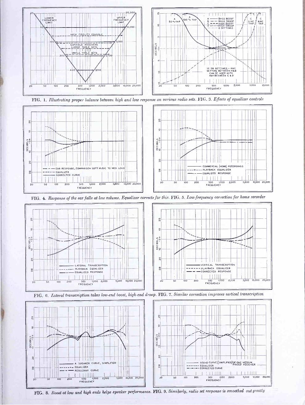
II LOWER
FREQUENCY LIMIT
UPPER FREQUENCY
LIMIT
Îij;1 HIGH FIDELITY CONSOLE l'`
200
CONSOLE LARGE - SMALL -
TABLE
RECEIVERS
- -RLE
SETS
SETS
, 0 lit
400 1250 III III I i1 50 200
FREQUENCY S,V00 10,000 20,000
n
N
U 1
w G
o -
A 50 NJTAP
100 ti TAP
I I 1 11 1 1
BASS / .Di i
C C
5 KC 1 KC TAP / AP _
A- BOOST B - - BASS DROOP C -- -HIGH BOOST D - - -- ,
HIGH 0 SETTINGS
DROOP / /
/
V
I
Iii! , i
15 SETT
DB SETTINGS- NG BETWEEN
ANY A&B .,
CAN BE USED WITH ANY BETWEEN C &D
I I I IIILI I
20 50 100 200 500 1,000 2,000 5,000 10,000
FREQUENCY
FIG. 1. Illustrating proper balance between high and low response on various radio sets. FIG. 3. Effects of equalizer controls
0 N
O
y, + J O W 1
m
W GO
O N
m G
`\N
--
- - - EAR RESPONSE, COMPARISON SOFT MUSIC TO MED. LOUD
EQUALIZER CORRECTED CURVE
111111 l 1 III 1 1 11
20 50 100 200 500 1,000 2.000 5,000 10,000 20,000
FREQUENCY
0 N
O
ut+ J O mI
V W p O
O N
ó
-+ \ \\\ \ // - . - COMMERCIAL RECORD NGS (HOME)
PLAYBACK EQUALIZER
---- --EQUALIZED RESPONSE
I I I
I
I I5,000 00 20 50 100 2 I 5I 1,I` 000 2,0 00 10,000 20,000 FREQUENCY
FIG. 4. Response of the ear falls at low volume. Equalizer corrects for this. FIG. 5. Low frequency correction for home recorder
o N
O
O Wj
u W Go
O N
m G
-
\
\ -i i .\
-
LATERAL TRANSCRIPTION --- --- PLAYBACK EQUALIZER --- EQUALIZED RESPONSE
I 5I I I
1 11,000 j00 20 50 100 200 5,000 10,000 20,000 FREQUENCY
o N
O
JO W 1
v W
O G
O N
m G
' \ \ \ i ' -_ - --
TRANSCRIPTION VERTICAL
PLAYBACK EQUALIZER - - -CORRECTED RESPONSE
1 I I 1 ,000 2,000 5000 10 000 20,000 20 50 100 200 0 I 500 FREQUENCY
FIG. 6. Lateral transcription takes low -end boost, high -end droop. FIG. 7. Similar correction improves vertical transcription
°
N
0
IJ
1
B U W GO
O N
mG
ll I I .\
-at, `` +
R , '
ii A SPEAKER CURVE, S MPL FIED
' - .... - EQUALIZER
-".. '-'- RESULTANT CURVE
I I I IIIIll 1 I I
20 50 100 200 500 1,000 2,000 5,000 10,000 20,000
FREQUENCY
Ñ
O - -`% I
1
CURVE(5
CURVE
1111111
MPLIFIED)OF PRICED
1
ONE
1
MEDIUM RECEIVER
1111111
SOUND EQUALIZER -- CORRECTED
1 1
N
20 50 100 200 500 1,000 2,000 FREQUENCY
5,000 10,000 20,000
FIG. 8. Boost at low and high ends helps speaker performance. FIG. 9. Similarly, radio set response is smoothed out greatly
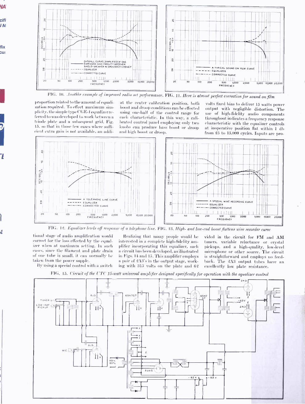
6J5
o N
ó
2
e ;
OVERALL CURVE(SIMPLIFIED)Cr ONE EXPENSIVE HIGH FIDELITY RECEIVER SINGLE -SPEAKER IN OPEN BACK CABINET EQUALIZER
CORRECTED CURVE
I L I l I I1111 1 I I I
00 500 1,000 2.000 FREQUENCY
5.000 10,000 20,0
FIG. 10..4nothr
U
o
o lV
Ó A TYPICAL SOUND ON FILM CURVE EQUALIZER
- CORRECTED CURVE
III 20 50 100
I I I 111111 I I I
200 500 1,000 2,000 FREQUENCY
5,000 10,000 20.000
example of improved radio set performance. FIG. 11. Here
proportion related to the amount of equali- zation required. To effect maximum sim- plicity, the simple type CGE -1 equalizer re- ferred to was developed to work between a triode plate and a subsequent grid, Fig. 15, so that in those few cases where suffi- cient extra gain is not available, an addi-
is almost perfect correction for sound on film at the center calibration position, both boost and droop conditions can be effected using one -half of the control range for each characteristic. In this way, a cali- brated control panel employing only two knobs can produce bass boost or droop and high boost or droop
U w0. o-
o N
m O
20 50
r
A TELEPHONE LINE CURVE EQUALIZER CORRECTED CURVE
I I Will
100 200 SOO 1,000 2,000 FREQUENCY
5,000 10,000 20,000
volts fixed bias to deliver 15 watts power output with negligible distortion. The use of high -fidelity audio components throughout indicates a frequency response characteristic with the equalizer controls at inoperative position fiat within 1 db from 25 to 15,000 cycles. Inputs are pro-
o N
O
m
ú w o-
0 N
A SPECIAL WIRE RECORDING CURVE O EQUALIZER
CORRECTED CURVE
II I I I I 1 1111 I I I
20 50 100 200 500 1,000 2,000 5,000 10,000 20000 FREQUENCY
FIG. 12. Equalizer levels off response of a telephone line. FIG. 13. High- and low -end boost *flattens wire recorder curve
tional stage of audio amplification would correct for the loss effected by the equal- izer when at maximum setting. In such cases, since the filament and plate drain of one tube is small, it can normally be taken from the power supple.
By using a special control with a switch
Realizing that many people would be interested in a complete high -fidelity am- plifier incorporating this equalizer, such a circuit has been developed, as illustrated in Figs. 14 and 15. This amplifier employs a pair of 2A3's in the output stage, work- ing with 315 volts on the plate and 62
vided in the circuit for FM and AM tuners, variable reluctance or crystal pickups, and a high -quality, low -level microphone or other source. The circuit is straightforward and employs no feed- back. The 2A3 output tubes have an excellently low plate resistance.
FIG. 15. Circuit of the UTC 15 -watt universal amplifier designed specifically for operation with the equalizer control
TUNER L - -1
OW -IMP PICKUP I I
MIC.
X
e
J
115 V. 60ti ^- f '
yJ i,
X
M',
1
4
I I Y J
_L
2A3
TI e
1 I
r
r
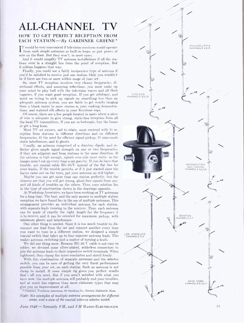
ALL- CHANNEL TV HOW TO GET PERFECT RECEPTION FROM EACH STATION -By GARDINER GREENE IT would be very convenient if television receivers would operate
from such simple antennas as built -in loops, or just pieces of wire on the floor. But they won't, in most cases.
And it would simplify TV antenna installations if all the sta- tions were in a straight line from the point of reception. But it seldom happens that way.
Finally, you could use a fairly inexpensive type of antenna if you'd be satisfied to receive just one station. Only you wouldn't be if there are two or more within range of your set.
So, since TV reception involves very choosy frequencies, di- rectional effects, and annoying reflections, you must make up your mind to play ball with the television waves and all their vagaries, if you want good reception. If you get arbitrary, and insist on trying to pick up signals on something less than an adequate antenna system, you are liable to get results ranging from a blank raster to snow storms in your cooking demonstra- tions, and watered -silk effects in your Keystone cops.
Of course, there are a few people located in spots where a piece of wire is adequate to give strong, static -free reception from all the local TV transmitters. If you are so fortunate, buy the house or get a long lease.
Most TV set owners, sad to relate, must contend with 1) re- ception from stations in different directions and on different frequencies, Q) the need for efficient signal pickup, 3) man -made static interference, and 4) ghosts.
Usually, an antenna comprised of a director, dipole, and re- flector gives ample signal strength on one or two frequencies, if they are adjacent and from stations in the same direction. If the antenna is high enough, signals over -ride most static, so the images aren't cut up every time a car goes by. If you do have that trouble, use coaxial cable RG -59/U instead of the flat line for your leadin. If the trouble persists, or if it just started since the leaves came out on the trees, put your antenna up still higher.
Maybe you can get more than one station perfectly, but the chances are that you will get strong, ghost -free signals from one, and all kinds of troubles on the others. Then your solution lies in the type of construction shown in the drawings opposite.
At Workshop Associates, we have been working on TV antennas for a long time. The best, and the only answer to multiple station reception we have found lies in the use of multiple antennas. This arrangement provides an individual antenna for each station, with separate leads running to the receiver. Thus, each antenna can be made of exactly the right length for the frequency it is to receive, and it can be oriented for maximum pickup, with minimum ghosts and interference.
One other thing is needed. Since it is too much trouble to dis- connect one lead from the set and connect another every time you want to tune in a different station, we designed a simple coaxial switch that takes up to four separate antenna leads. This makes antenna switching just a matter of turning a knob.
We did one thing more. Because RG -59/U cable is not easy to solder, we devised some silver -plated, solderless connectors to join the antenna leads to their respective switch terminals. When tightened, they clamp the inner conductor and shield firmly.
With this combination of separate antennas and the selector switch, you can be sure of getting the very finest performance possible from your set, on each station. Such an antenna is not cheap to install. If some simple rig gives you perfect results that's all you need. But if you aren't satisfied with what you have now, the multiple antenna will probably end your troubles, and at much less expense than more elaborate types that may give you no improvement at all.
*President, Workshop Associates, 66 Needham St., Newton Highlands, Mass.
Right: Six examples of multiple antenna arrangements for different areas, and a view of the coaxial antenna selector switch
June 1948 - formerly FM, and FM RADIO -ELECTRONICS
CHICAGO CHANNELS 4,5,7,9
PHILADELPHIA CHANNELS 3,6,10
y v
LOS ANGELES CHANNELS 2,4
.:v
WASHINGTON BALTIMORE
CHANNELS 4,5,7,9
BOSTON CHANNELS 4,7
NEW YORK CHANNELS 2,4,5,11
31
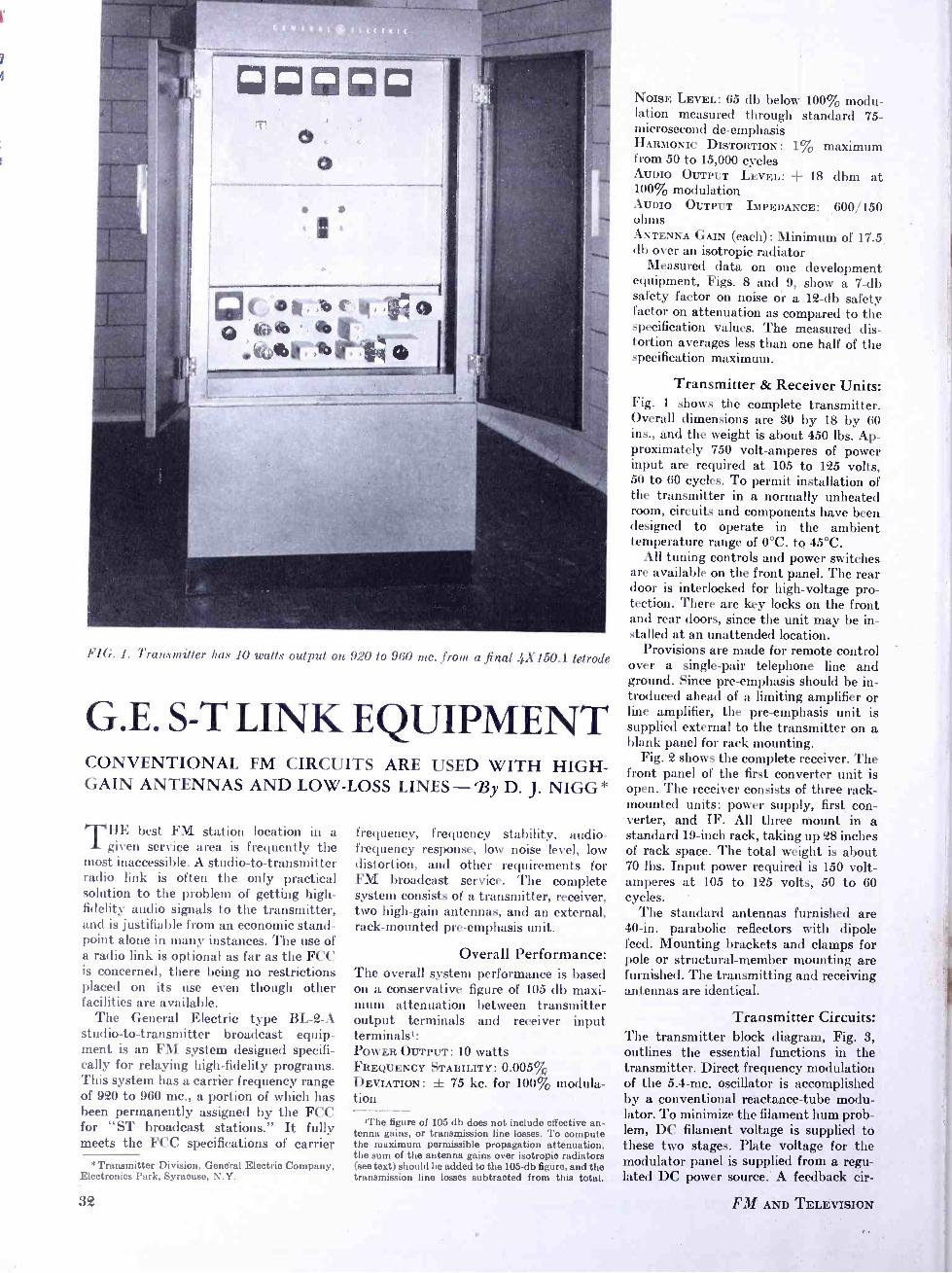
FIG. I. Transmitter has 10 watts output on 9_'O to 960 mc. from a final 4X150A tetrode
G.E. S -T LINK EQUIPMENT CONVENTIONAL FM CIRCUITS ARE USED WITH HIGH - GAIN ANTENNAS AND LOW -LOSS LINES -By D. J. NIGG*
THE best FM station location in a given service area is frequently the
most inaccessible. A studio -to- transmitter radio link is often the only practical solution to the problem of getting high - fidelity audio signals to the transmitter, and is justifiable from an economic stand- point alone in many instances. The use of a radio link is optional as far as the FCC is concerned, there being no restrictions placed on its use even though other facilities are available.
The General Electric type BL-2-A studio -to- transmitter broadcast equip- ment is an FM system designed specifi- cally for relaying high -fidelity programs. This system has a carrier frequency range of 920 to 960 mc., a portion of which has been permanently assigned by the FCC for "ST broadcast stations." It fully meets the FCC specifications of carrier
*Transmitter Division, General Electric Company, Electronics Park, Syracuse, N.Y.
32
frequency, frequency stability, audio - frequency response, low noise level, low distortion, and other requirements for FM broadcast service. The complete system consists of a transmitter, receiver, two high -gain antennas, and an external, rack -mounted pre -emphasis unit.
Overall Performance: The overall system performance is based on a conservative figure of 105 db maxi- mum attenuation between transmitter output terminals and receiver input terminals': POWER OUTPUT: 10 watts FREQUENCY STABILITY: 0.005% DEVIATION: ± 75 kc. for 100% modula- tion
'The figure of 105 db does not include effective an- tenna gains, or transmission line losses. To compute the maximum permissible propagation attenuation, the sum of the antenna gains over isotropic radiators (see text) should be added to the 105-db figure, and the transmission line losses subtracted from this total.
NOISE LEVEL: 65 db below 100% modu- lation measured through standard 75- microsecond de- emphasis HARMONIC DISTORTION: 1% maximum from 50 to 15,000 cycles AUDIO OUTPUT LEVEL: + 18 dbm at 100% modulation AUDIO OUTPUT IMPEDANCE: 600/150 ohms ANTENNA GAIN (each) : Minimum of 17.5 db over an isotropic radiator
Measured data on one development equipment, Figs. 8 and 9, show a 7 -db safety factor on noise or a 12 -db safety factor on attenuation as compared to the specification values. The measured dis- tortion averages less than one half of the specification maximum.
Transmitter & Receiver Units: Fig. 1 shows the complete transmitter. Overall dimensions are 30 by 18 by 60 ins., and the weight is about 450 lbs. Ap- proximately 750 volt -amperes of power input are required at 105 to 125 volts, 50 to 60 cycles. To permit installation of the transmitter in a normally unheated room, circuits and components have been designed to operate in the ambient temperature range of 0 °C. to 45 °C.
All tuning controls and power switches are available on the front panel. The rear door is interlocked for high -voltage pro- tection. There are key locks on the front and rear doors, since the unit may be in- stalled at an unattended location.
Provisions are made for remote control over a single -pair telephone line and ground. Since pre- emphasis should be in- troduced ahead of a limiting amplifier or line amplifier, the pre- emphasis unit is supplied external to the transmitter on a blank panel for rack mounting.
Fig. 2 shows the complete receiver. The front panel of the first converter unit is open. The receiver consists of three rack - mounted units : power supply, first con- verter, and IF. All three mount in a standard 19 -inch rack, taking up 28 inches of rack space. The total weight is about 70 lbs. Input power required is 150 volt - amperes at 105 to 125 volts, 50 to 60 cycles.
The standard antennas furnished are 40 -in. parabolic reflectors with dipole feed. Mounting brackets and clamps for pole or structural- member mounting are furnished. The transmitting and receiving antennas are identical.
Transmitter Circuits: The transmitter block diagram, Fig. 3, outlines the essential functions in the transmitter. Direct frequency modulation of the 5.4 -mc. oscillator is accomplished by a conventional reactance -tube modu- lator. To minimize the filament hum prob- lem, DC filament voltage is supplied to these two stages. Plate voltage for the modulator panel is supplied from a regu- lated DC power source. A feedback cir-
FM AND TELEVISION

AUDIO INPUT
4.57 -4.78 MC.
82.20-85.95
6H6 8AG7
CALIBRATION
7F8
920-960 MC.
808 -848
XTAL CONY. 1N 218
14.98 -15.70
7F8 I 2ND IF 10.7 MC.
2ND CONY.
6J6 6..18 12 AU7
OSIGNAL
12AÚ7
7F8 2
7ÁG7 7ÁG7 7AG7 7AG7 7AG7
DISC.
7A6 j
8AG7
TUNIN
7 F8 2
XTAL OSC.
7AG7
TRIPLER 600/150-OHM +18 DBM
7N7 7F7
FIG. 3. The transmitter employs direct frequency modulation. FIG. 4. Receiving circuit is of the double -conversion type
cuit, consisting of an RF amplifier and FM discriminator, is connected around the modulator and oscillator. This feed- back circuit performs the normal func- tions of reducing the distortion and noise in the modulator and oscillator circuits. In addition, the discriminator is used to stabilize the oscillator frequency by sup- plying a DC error voltage to the reactance tube. Both the oscillator and discriminat- or have temperature -compensating com-
ponents. The calibration crystal shown on the
block diagram consists of a conventional quartz crystal used as a high -Q wave - meter. This crystal wavemeter is loosely
coupled to the oscillator. The voltage built up across the crystal, when excited at a resonance, is rectified by a germanium diode, and indicated on the tuning meter. By this means, it is possible to tune the oscillator frequency to the calibration - crystal frequency with about 50 -cycle
accuracy. A manual cut -out on the feed-
back circuit permits adjusting the oscil-
lator to the calibration -crystal frequency without feedback. The feedback discrim- inator secondary tuning control can then be adjusted to bring the oscillator fre-
quency back to the calibration- crystal frequency with the feedback stabilization applied. The oscillator is now set to the reference -crystal calibrator frequency, and stabilized there by the temperature - compensated discriminator.
A unique and very useful additional feature of the calibration crystal arises from its extreme sharpness of resonance. It is possible to apply tone modulation to the transmitter and select the oscillator
- center -frequency component while reject- ing the side -band frequencies. This makes it possible to establish the 100% modula- tion level by means of the carrier null method, without resorting to external measuring equipment. As the tone modu- lation level is increased, the center fre-
quency nulls of the oscillator can be
counted directly from the calibration - crystal meter dips. With a 440 -cycle tone as an example, 100% modulation ( ±9.375 kc. at the oscillator frequency, which corresponds to ± 75 kc. at the output
carrier frequency) occurs at the 7th null. It is important to note that this oscil-
lator has only a relatively small influence on the final frequency stability. Reference to the block diagram, Fig. 3, will show that the 5.4 -mc. output of the modulator is multiplied only 8 times as it appears in the output frequency, the remainder of
FIG. 2. Complete receiver, with the door open on the first converter section
June 1948 -formerly FM, and FM RADIO -ELECTRONICS
the output frequency being contributed by the stable quartz- crystal oscillator. Since the modulated -oscillator frequency is 5.4 mc., only 43.2 mc. of the output is
actually contributed by the modulated oscillator. This 43.2 -mc. value is less than 5% of the output carrier frequency in the 920- to 960 -mc. range. Thus, it may be said that the output carrier is 95% di- rectly crystal- controlled and 5% crystal - referenced, the modulator frequency hav- ing been adjusted by using the calibration crystal wavemeter.
The 4.57- to 4.78 -mc. crystal oscillator uses a temperature -controlled G.E. Ther- mocell crystal. As a comparison of stabilities required of the two frequency - generating sources, i.e., the crystal os- cillator and the stabilized oscillator, it will be noted that the crystal oscillator fre- quency is multiplied 192 times while the stabilized oscillator is only multiplied 8
times. The quotient of these two figures is
24, which indicates that a stability of only 1 /24th that of the crystal oscillator is re- quired of the stabilized oscillator to have equal effects on the output carrier fre- quency. A figure considerably better than this is achieved in practice.
The double conversion scheme, used to heterodyne the output of the frequency multipliers with the modulator output, achieves a very high rejection of 5.4 -mc. sidebands in subsequent stages. Balanced converters are used in both cases to further reduce spurious frequencies. The first converter mixes the 5.4 -mc. modu- lator output with 28.65 mc., a frequency ratio of only 5.3 times. If single conver- sion were used, and the multiplication factor of 8 after mixing were to be main- tained, it would be necessary to mix the 5.4 -mc. modulator output with 114.6 mc. This would require mixing frequencies with a ratio of 21 to 1. Such a situation would make reduction of the 5.4 -mc. side - bands extremely difficult.
The last three doublers shown on the block diagram, Fig. 3, are mounted on a shelf behind the top panel, Figs. 1, 5,
and 6. All three stages employ forced -air- cooled 4X150A tetrodes. As a result of
the compact construction of these high-
33

frequency tubes, it is necessary to resort to only one cavity circuit. The plate cir- cuit of the final doubler consists of a radial cavity about 6 ins. in diameter. This cavity operates on the jundumental mode at the output frequency. Fig. 7 shows this cavity with the tube in place. The cavity itself operates at DC ground potential, with the plate voltage applied through a radial blocking capacitor, as shown. Note that the tube can be changed by the simple procedure of lifting it out. No dis -assembly is necessary. Cooling air is furnished to all three stages through the duet at the rear of the shelf. In the case of the final -doubler cavity, Fig. 6 shows the air -duct connected directly to the grounded cavity. Several holes are drilled in the periphery of the cavity to permit entrance of the cooling air which exhausts through the anode -cooling fins and open -
ings around the socket. The grid circuit of the final doubler is a half -wave, open -line
circuit tuned by a variable capacitor. It is similar in construction to the other two open -line circuits visible in Fig. 6. These circuits are, from left to right, plate cir- cuit of the first doubler, and grid circuit of the second doubler. Cooling air is supplied to these two stages through special air chambers connected to the main duct. A modification in the final de- sign permits removal of these tubes with- out moving an air duct. Their accessi- bility will be the same as shown for the final doubler. A jet of cooling air is di- rected against the tube seals at all three sockets.
Output coupling from the final circuit is accomplished by a fixed loop in the cavity, for loading into a 51.5-ohm im- pedance. A single -stub tuner and a crystal diode RF probe (not shown) are con- nected between the cavity output con- nector and the type N fitting in the top of the transmitter cabinet. A tuning stub
FIG. 5. This S -T link transmitter is designed for operation in an unheated building
34
permits sufficient adjustment of the load- ing, and the RF probe gives a relative in- dication of the voltage on the output transmission line. Rated power output of the transmitter is 10 watts, but this power can be reduced to any lower value. Separate front panel screen -voltage con- trols are provided on the last two stages to provide a means of reducing power to any desired level. An extension of tube life can be expected at lower power.
The transmitter can be adjusted for operation at any frequency in the 920 - to 960 -mc. range without the use of any external test equipment. The lower panel in Fig. 1 carries all the stages indicated on the block diagram except the last three doublers. The meter shown on this panel can be switched to each circuit for tuning. In addition, this meter has a switch position for the RF output crystal probe, used for tuning and loading the output stage. The meters on the top panel indi- cate plate voltage, individual plate cur- rents, and individual grid currents for the three 4X150A stages.
The illustrations of the center panel, Figs. 1 and 5, show the magnetic circuit - breaker power switch and other control equipment. A local- remote switch in the transmitter selects the method of control. When remotely controlled, the plate voltage is automatically applied after a 30- second filament warm -up period. After this delay, a pilot light at the remote con- trol point indicates that the plate voltage has been applied. Should an overload trip the plate voltage off, the pilot light at the remote control point is extinguished. The plate voltage can be immediately re- applied from the remote point without the 30- second time delay. Automatic power - failure reclosure is provided in the trans- mitter to re -apply all power automatically after momentary interruptions not ex- ceeding 2 seconds duration. Following power interruptions of longer duration, all power is automatically re- applied after a 30- second delay.
The transmitter is equipped with 3B25 xenon -filled high -voltage rectifier tubes, to permit operation at low ambient temperatures. If the transmitter is always operated in a heated room, type GL -866 -A rectifiers can be used as replacements.
Receiver Circuits: The block diagram in Fig. 4 outlines the essential functions in the receiver. At 1,000 mc., crystal mixers have a noise figure several db better than vacuum tube mixers. This is also the approximate point in the spectrum where present -day RF amplifiers become so noisy that only a very marginal improvement in signal -to- noise ratio can be obtained.2, 8 Ampli- fication at this frequency would require
aD.A. Quarles, "Radar Systems Consideration," Electrical Engineering, Volume 65, page 213; April 1946.
'L.W. Morrison, Jr., "The Radar Receiver," Bell Systems Technical Journal, Volume 26, pagé 710, Fig. 5.
FM AND TELEVISION

o
z
° '
s
Q
SPECIFICATION MAXIMUM
Ti
o 4 6 6o 2 4 6 60 2
ó o
MODULATING ti
1 4 6 Boo
o °
130 120 110 100 90 60 DB ATTENUATION
BETWEEN TRANSMITTER 6 RECEIVER
FIG. 8. Measured harmonic distortion of the system. FIG. 9. The signal -to -noise ratio
the use of special disc -seal or coaxial type tubes in cavity or coaxial circuits. It was felt that the additional complexity and tube cost involved was not warranted by any improvement that could be expected reasonably. From an overall system view- point, a far more economical and trouble - free source of improvement lies in the use of higher antenna gain and lower trans- mission line loss.
Based on this reasoning, it was decided to keep the receiver as simple as possible to insure trouble -free operation. Tests on a developmental model indicate excep- tionally good sensitivity. Fig. 10 shows measured sensitivity, for a 65-db signal - to -noise ratio, of 117 db below the 10 -watt transmitter power output. The curve shown is an average of results using sev- eral different mixer crystals. Expressed in the usual manner of rating receivers, this would be 107 db below 1 watt, or about 33 microvolts at 51.5 ohms. A very con- servative rating of 95 db below 1 watt has been placed on the receiver to take care of misadjustment and sub- standard crystals. This figure would be a conservative one to use in comparing system sensitivity with propagation attenuation.'' s The specification point is marked on Fig. 9.
All filament, DC supply, and meter wiring are on the front side of the panel, shown in Fig. 2, with ceramic feed-
through bypass capacitors providing con- nections to the circuit elements on the rear side of the chassis. Fig. 7 shows a rear view of the same unit with shield cover re- moved. An exceptionally clean layout of
glas shield covers all exposed voltages on the front, with holes through this shield providing access to the screwdriver tuning adjustments. All tuning adjustments and tube replacements are made from the front of the unit.
The crystal mixer circuit is the rec- tangular box at the right side of the con- verter unit, Fig. 2. This box consists of a half -wave resonant coaxial transmission - line circuit with the ends shorted, thereby having a voltage maximum at the center. The antenna input is connected to the center conductor a short distance from one end, and the mixer crystal a short dis- tance from the other. The lower half of the mixer circuit cover plate is removed to change the mixer crystal. The tuning slug shown on the top half of the cover plate tunes the mixer circuit to the carrier frequency. Local oscillator injection is
accomplished by capacity coupling to the
FI(.. G. The final 4X150A doubler stages are carried in this section of the transmitter
RF circuit elements results from this feed- through system of wiring. A plexi-
+D.E. Kerr, " Propagation of Very Short Waves," Part I, Electronics, January, 1948; Part II, February, 1948.
6A.L. Durkee, "Results of Microwave Propagation Tests on a 40 -Mile Overland Path," Proceedings of the IRE, Volume 36, 6 February, 1948.
FIG. 7. Rear view of the first converter unit of the receiver, with the shield cover removed
June 1948 - formerly FM, and FM RADIO- ELECTRONICS
maximum voltage point at the center of the mixer circuit. The small hole in the cover plate provides screwdriver access to an adjustable probe which extends through a clearance hole in the chassis, and provides capacity coupling to the local oscillator circuit.
The local oscillator voltage source is a crystal oscillator, operating at about 15
mc. and multiplied 54 times to a frequency 112 mc. below the incoming carrier fre- quency. The tube types and multiplica- tion factors are shown in Fig. 4. Only standard receiver -type tubes are used.
The actual circuits are shown in Fig. 7,
the crystal oscillator stage being located slightly above the center of the chassis, with the succeeding multiplier stages in a clockwise arrangement. Lumped circuits are used through the 140 -mc. stage, quarter -wave transmission -line circuits are used in the 400 -mc. stage, and a com- bination circuit in the 800 -mc. final - multiplier plate circuit. The three triplers are conventional push -pull multipliers with loosely coupled high -C tank circuits. The 192AU7 is a relatively new tube, con- sisting of a double triode in a miniature
(Continued on page 46)
35

FUTURE OF FM AND TV (Continued from page 15)
luncheon. It seems to me appropriate that we should take stock of where we are and where we are going.
It is my opinion that no broadcaster in America can be satisfied with the status quo - that he must always be looking to the horizons beyond - and that it is his responsibility to participate to the fullest extent of his capabilities in planning for the radio services of the next generation.
I can assure you that the present mem- bership of the Federal Communications Commission sees its job as one of par- ticipation in such planning.
And as all of you know by actions of the last few weeks, the Commission believes its responsibilities encompass that of initiating the planning.
Perhaps the most important decision facing all of us as we think about the fu- ture aural broadcasting service is that in- volving the relationship of FM and AM.
Some broadcasters apparently think of FM as a new and improved method of transmitting programs; others think of FM as a way to get a second station in their community and plan a separate broadcast service over the medium. The interest of others is wholly that of the "insurance " approach to FM - they just don't want to be left out if there is anything to this "new fangled gadget "; and others, so far as I can tell, just haven't thought about it.
The networks are making it perfectly clear that they look to FM as an improved medium for the transmission of programs. They apparently think of their networks as providing a single program service either through AM or FM or both of them. But network affiliates, the indi- vidual broadcasters, have not accepted that point of view.
Some of them do not like the network policy of duplicating programs as is evi- dent by the inquiries that we receive at the Commission.
I do not propose to go into that subject now. My only purpose at this time is to point out that the relation between AM and FM is one that requires some hard thinking and planning if we are to fix our goals for a sound aural -broadcasting service for the future.
The broadcasters who do not have AM licenses but who have FM licenses only do not face the problem of planning that the AM broadcaster does or that the AM -FM broadcaster does. He knows what his plans are for the future. He accepts FM as the static -free, fade -free, and interference -free service that we all know it is. He has elected to stake his future in the develop- ment of this service rather than put his money into a daytime AM station or an AM station with a highly directionalized pat tern.
The interference free service area that he can serve by FM has attracted him to
36
this newest development in the aural broadcast field.
Of course, the FM enthusiast believes that FM is destined to replace AM in all but the sparsely settled areas of the na- tion. He likewise believes, when he con- siders the fact that only a little over a million FM sets were produced last year, that everyone is conniving against the realization of his hopes. He is a plucky fellow, a pioneer who is fighting for what he believes, who thinks that every day is the day on which FM should be accepted by all American broadcasters as the future aural broadcasting service for this country.
And there are a lot of good sound rea- sons that support his point of view. One of them I have already referred to: FM is static -free, fade -free, and interference - free. The advantage of freedom from interference is becoming increasingly im- portant to broadcasters as more and more standard broadcast stations come on the air.
Also, FM has high fidelity capabilities. Many who have FM stations are exploit- ing the full fidelity potential of this service.
The Continental Network, regional FM networks throughout the country and a few independent FM broadcasters have a program service that will demonstrate the full fidelity capabilities of FM. It is not possible to demonstrate the fidelity capabilities of FM by duplicating network AM programs on FM stations over 5,000 - cycle lines. FM will really have its chance when 15,000 -cycle lines are available for networking or when microwave relays can be constructed for the purpose of net- working or when there is a sufficient number of FM stations on the air to pro- vide for network operations by re- broadcasting.
I am hopeful - and I expect - that the time is not too far off when the major networks as well as the more youthful FM networks will provide facilities that will permit the demonstration of the high fidelity capabilities of FM.
The FM allocation plan set forth in the rules of the Commission provides for the use of the 88 -108 mc. band on a planned basis. The plan reflects the geographic availability of the FM channels on an engineering basis. This is in contrast to the "topsy- like" growth of AM broad- casting in this country. I am sure that with what we know today about the social and economic impact of broadcasting and with the engineering knowledge resulting from the experiences of more than a quarter of a century of operation we could build a wonderful service in the standard broadcasting band. Hindsight is wonder- ful - except that it is difficult to use it. We can - and we have - taken ad- vantage of our experience gained in past years to provide a more orderly growth for the aural broadcasting service of the future.
The FM allocation plan provides for uniformity of power within given areas of the country. This is not an unimportant fact. This fact eliminates the present competitive inequality that exists be- tween AM stations. It paves the way for competition between stations on the basis of quality of programming, initiative, enterprise, imagination in serving the public interest.
We can have more FM stations than we can ever have in the standard broad- cast band. This means that more com- munities can be served and that there will be more free competition.
I suppose it is inevitable that some broadcasters continue to hold back in thinking about FM as the aural broadcast medium of the future. There are always those who are satisfied with the status quo.
It is not surprising that some broad- casters are willing to let the other fellow carry the cost of developing this improved service with the expectation that they will get in on it when it can become profitable. Those broadcasters will have lost the thrill of pioneering, of developing a new service that will more adequately serve the people of their community - of hav- ing participated in the planning for the future aural broadcast service.
In my opinion it will be a red letter day in the history of American broadcasting when you broadcasters make up your mind that you can provide a superior aural broadcast service through the use of Frequency Modulation and when ¡du direct your efforts to planning for that conversion.
I know it is difficult in a field as dynamic as broadcasting to predict what the situa- tion will be in the future but to me, in the light of what we know today, it seems almost inevitable that FM will, within a generation, largely replacé AM.
In some of its elements, television presents problems similar to those we face in the aural broadcasting field. The major problem we face in planning for the future is how to get television service to all the people of the country and, more than that, how we can provide a nationwide competitive system to furnish this service.
We at the Commission are determined that there will be enough channels avail- able in this country to provide for a truly nation -wide competitive system and one that will serve all of the people of this country and not just those fortunate enough to live in metropolitan areas.
We at the Commission likewise feel that opportunities to get in the television field should be afforded to as many people as possible and 12 channels provide op- portunities for only a limited number of people to get in the television business.
It does not take much of a prophet to state now that it is a question of only a few months until all television channels available in major metropolitan areas are
(Continued on page 41)
FM AND TELEVISION
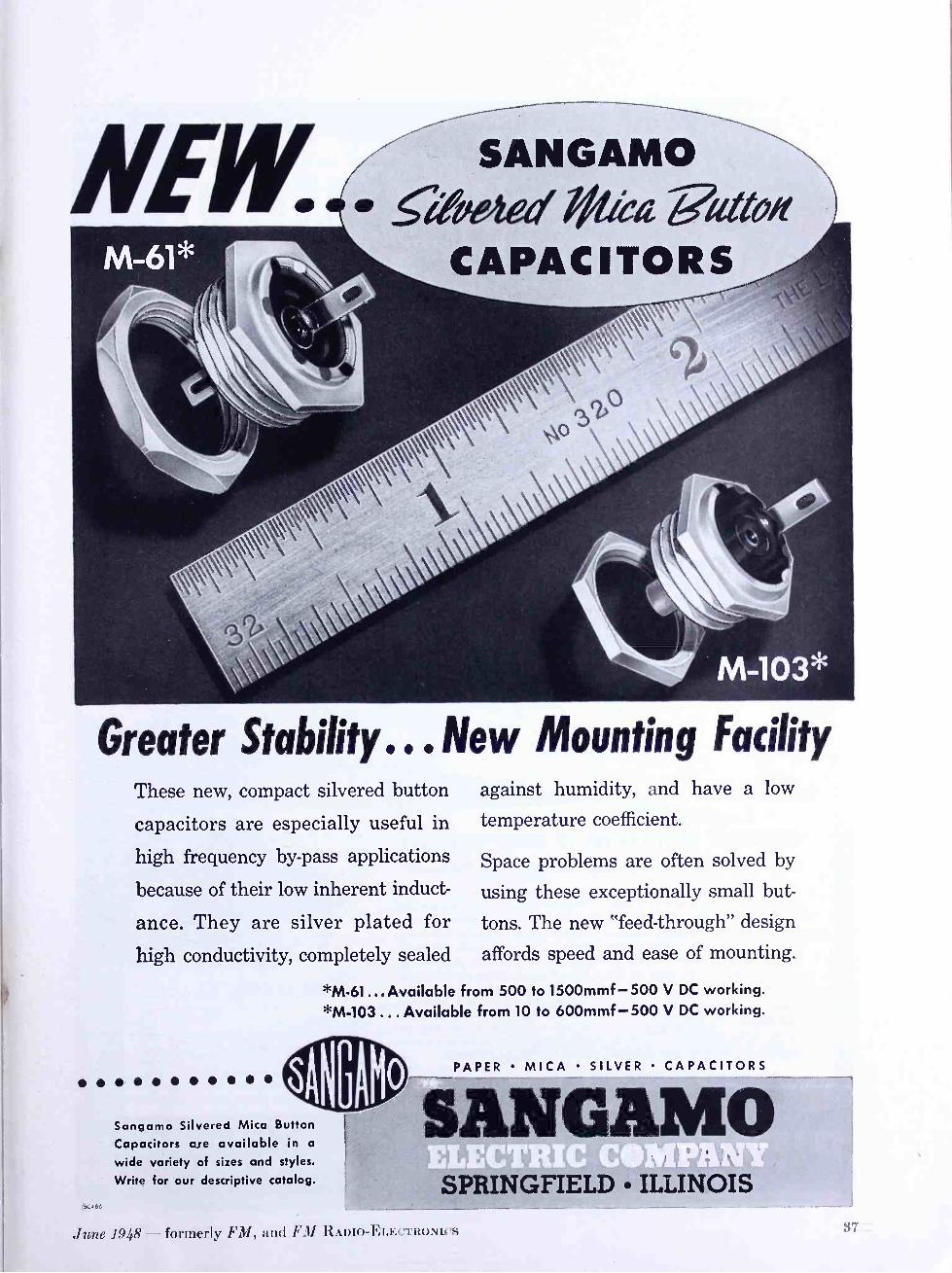
NEW SANGAMO ;2W *iéiz 7?attew
CAPACITORS
Greater Stability... New Mounting Facility These new, compact silvered button
capacitors are especially useful in
high frequency by -pass applications
because of their low inherent induct-
ance. They are silver plated for
high conductivity, completely sealed
against humidity, and have a low
temperature coefficient.
Space problems are often solved by
using these exceptionally small but-
tons. The new "feed- through" design
affords speed and ease of mounting.
*M- 61...Available from 500 to 1500mmf -500 V DC working. *M -103 ... Available from 10 to 600mmf- 500 V DC working.
Sangamo Silvered Mica Button
Capacitors are available in a
wide variety of sizes and styles.
Write for our descriptive catalog.
PAPER MICA SILVER CAPACITORS
SANGAMO SPRINGFIELD ILLINOIS
June 194h' formerly FM, uii<I F.11 HAI)lu-I:i.Ecritutitcs
..1111 r.w.tYhY«- 1111 .,. rr11¡1,1. il..R.\rl. _ X.:: .....«t.....1*.1ta...t1.. ..r. .\t 1.11tM\ .« ..t.r...r.«..tr......rl.r.. i .r.tarr.._ w'r.'_ r::!"'t!!:::;1 .IRsti rr1. +tyU. ... di. ~ ..i..ir\11..:i: Iir.1.111
,, ../71t.1iw .tYYY.,.,It11tl\/YiM«I.f .11r. \, r.s.r,. ! ... ,..rrM.M.i.....r.... tI.YI: ' I1t.. .ir,rtili:u.,y..UHw}i::.:iiu..t Ìli:ut, NO1#'IERI 1.1Y.11111+:,.ii.r:..ut Ir .1--.,..l...f«s..w...N 'lf... r.t.a. .M/r r...r... .pí+OS:r._; ü...11 tll/.:,..îw..i:. ::` ii:w:: .... : RIDE
t.. _,.. 1 - -
THE '.wr.r, n.. /. V..t.li.
"' T t.1.... ,, - .x:,,- M :;;:....,.. 1,..,, R F
i ,+f...........1-.....w.o..w. r....rnr.r'.r.rri.al«.... : t'-:i, IIw.r«w+2,Ir rrr. ,--.rr.r+.l.r. .r/ w K,rr r,r/(..Iiri. . ......r...... 1.1/ I.Or+Yr-.-. 11_ + t/P\it -v-- t: r1 w
....:. r:jr-- - r. .l *r. .n-^ -`..1aP.rr.+1::i ...'':,.....,
Iéf+i11i:.i tr/tw«-\1r:s1 u/.r..i' u.si.. ,../lr..,.: ' Sao 1rl . Y/.f.f.1 ;;..- r..r. 1w .fi r- :i::-111 \¡r..
r..1/. .Y+' t.rir.s-.....1 t.r1w1r rirt«...1rJ iZ.C.r... . ..r1,rw 1.11 ..Yw1 Iar
, !. .+n.1 1 .. 1--
+ri.1s r.
Y..", :. M..
....,. v 1 .. . .--:. :; ......
'FIRS Ps
PROF FRO* .. M
OÉEN/IISIpN SERVICING
xow_TwoáKs
T
;:i.::::: a!!. i..,.......::' 1r,.. -.::..i...... t.t« IJJ.`, i. .*: :...r^ . 1y ..... y1.:. !::''......1Y .....!..1 .... , tr1t..at..rn
i u1... r...rrrnn.i ....I. ii.ïu..1..... ::::::::1::.,1. .vr .Y::í.. ̂ :: ..i. ... ./11..ii ....1. .í`i.i`
.1... .r....t. '... r..1ta.1 .., ::::r..:.: I.
..: ::':: ::. ; /1f , I. Iaw...'
.11141.4 Ill r. Yw1/ltt.l /
.. n: /. I1
.
141ANIU AL
Separate Books
_ PIUS 2 p tete ooks Over 40 Pages
nd Index, Complete ais.
T`'' WORKS
Rider Manu
1 Y p the other famous 47 television
"HOW H volume to the 19qó manu-
facturers.
bout leading t companion be known ° industry's The 5 °me
imp °.ton must b produced
by the y's le di
$1500
that u Here is °n d kit) Prod publishing
this
used as on all Rider Manuals. 4eceiVerseverything and in P requiring
the Olen
NO of
goose -leaf binder d size; hit unfold to the rets. Authentic
factory factu ed ¡n 9pO type
been NT information. escrip rugged YP reproduced PAGE at ¡on. Lions
Diagrams hove
Spreads and GIANT complete r 9ht mati. Cire'thenti Tables- Chassis
use sox
Double
Here is °ev0lui nment -VO tage ° ̂ d Resistance esistan
Explanation of the
information. Alignment-Voltage I ¡9 d. Sections-
Sound
in+ °.mat ¡Pprts Lists.
tterns thing óÓK need. 200 P
°gesl ExPR.F. Pa very s in Schein E (ab FreQuenc Waveform Views -Ports
"NOW Antennas-Channel nt
BOOK and Sweep
encie ts-
de lying theories ChOnnepl ¡g ̂ ^1ent
and Servicing
Sound °Power Supplies-Alignment - ara Accurate, SeP Complete.
ti:ii:l/;: 1.::.:SSi ÁtiwYÿ jÿíii ru... .. 1t.r-. i:i`r
Ìúr . s :-:a =swr::::
° :f -r:: .;..«! -+r :: 3
3
/ ...NI
": .: .W+
'i Ir! 4:
is not yet Even if television
it will be in
in your area, Start learn -
the ñear future in televi-
sion now what Is and how
receivers, book
each works
each covers
essential under-
lying theory you should be 2.7
familiar with.
Separate INDEX. _ .-...«i::: .nt1Y.1r ./'.1.s.... 1HIt. . ... .srli.. ... .i...l
._GS: M*yr. s.1tllYYI Oita. 1wrR.....r.. .,11:2:;:t ......... u u11/1. su....:fir.. ......-...,... rs««.-ii.á.tiaarsara...:áiúii1'/rw.Y.1\ii-.. ....
'. . it `.i..t .-. t r+l s.a, t "CERTAINLY WE HAVE ALL 17 RIDER MANUALS, and have ordered the Television Manual" "Certainly we have all 17 Rider Manuals and have ordered the Tele- vision Manual. I can't imagine any high class, efficient radio service laboratory operating satisfactorily without them. I'll have Volume 18 on the shelf, too, as soon as it's published,"
Sav R. B. GRAF SERVICE MGR.
Ward Radio & Appliances, Silver Spring, Md.
A conspicuous characteristic of Rider Manual owners is their unswerving loyalty to "The World's Greatest Compilation of Radio Servicing Data." This is a steady patronage born of the benefits provided by Rider Manuals during eighteen years of continuing service to the servicing industry. Copies of Vol. 1, published 18 years ago, are still paying profits to their owners. Give your shop the sign of Successful Servicing -a com- plete set of Rider Manuals.
JOHN F. RIDER, PUBLISHER, Inc., 404 Fourth Avenue, N. Y. 16 Export Agent: Rocke International Corp., 13 E. 40th St., N.Y.C. Cable ARLAB
RIDER MANUALS
ALL 17 Volume XVII
Volume XVI
Volume XV
Volumes XIV to VII (ea. vol.) Volume VI
Abridged Manuals I to V (one vol.) Record Changers and Recorders Master Index, covering Manuals, Vols. I to XV
$15.00 8.40
18.00 15.00
11.00 17.50
9.00
1.50
l,rr¡1 :é11r1 u -
nreftlii R4194110 41
...,1rt. . I... . 1,..,, w..s ytt.. 1a . :...,.. IR./.+
7/414 SUCCESSFUL SERVICING
:
NOTE, the Mallory Radio Service Encyclopedia, 6th Edition, makes reference to only one source of Rodio Receiver Schematics. -Rider Manuals.
FM AND TELEVISION

NO GUY WIRES
Self- Supporting Steel
TOWERS for TV and FM
Galvanized Steel -Will Last A Lifetime! SAFE - Ladder to Top Four -Post Construction for Strength Easy to Assemble and Erect Withstands Heaviest Winds
ATTRACTIVE LOW PRICES! Designed for easy shipment and simple erection.
Assembled with a wrench in a few hours. Eight
stock sizes, from 22 ft. to 67 ft. (Spread at base
equal to 1/5 height) Net prices $63 to $210 FOB
Kansas City, Mo. Shipping weights, 340 lbs. to
1230 lbs. Shipped 4th class freight.
Sold Direct Only. No Jobbers.
Write for Complete Free Information!
TheVESTO Co., Parkville, Mo.
introduces...''
THE "S4E4 20 "TUBE
FM RECEIVER Unexcelled in
PERFORMANCE
Remarkably LOW IN COST
Designed to satisfy the most critical professional or amateur, the Collins "Super 20" offers unsurpassed value in an FM
RECEIVER. The advanced 20 -Tube circuit fea- tures: Armstrong FM, built -in stabilized power supply and audio amplifier capable of 10 -watt output; new 6AL7GT tuning eye, connections for 2 types of phono pick -up, output impedances to match 4 to 20 ohm voice coils and 500 ohm line, and variable bass and treble tone controls with attenuation and boost for upper and lower registers.
Write Today for Complete Details
COLLINS Audio Products Co., Inc.
P. 0. BOX 368 WESTFIELD, N. 1. WE -2 -4390
June 1948 - formerly FM, and FM 11An10- FT.1'acTRoNTrs
..AS DISTINCT IVE AS YOUR
Surprenant's improved SPIRA- LON is just that! SPIRALON is a
thinwall plastics insulated wire with one, two or even three spirally inlaid solid color stripes. These, in turn, provide a total of up to four colors per wire ... or a maximum of 1120 distinctively coded combinations to make wire identification easy - even in the most complex installations.
Non -inflammable, non -corrosive, flexible and tough, SPIRALON is obtainable with or without a thin jacket of transparent Dupont nylon to further preserve every electrical property and resist oils, dilute acids, alkalies, abrasion and fungus attack. SPIRALON is approved under specification JAN -C -76 type WL ... it will not fray, crack or rot - and offers a higher rupture point than braid or lacquers. These superior features are available a.t no extra cost in all standard wire types
and sizes - or to your most exacting specifications. Write today for samples and technical data.
SPIRALON "O" (with nylon jacket) (without nylon jacket)
SPIRALON
Write DEPT. D
CO. "Pioneers in
Plastics Extrusions"
,.. . ...,., 4. ,
.
9 Washington S Boston 7, Mass. 0 1947 s. MFG. CO.
EQUALLY MATCHED
40
Split the reed assembly of a Mallory vibrator down the middle and the two halves will match each other so accurately that no scale made will register a significant difference.
This precise distribution of weight is a major factor in assuring accurate output, reliable operation and long life.
Mallory Vibrators Make
the Best Replacements
Such careful manufacturing makes Mallory vibrators free of bounce and chatter and dependable in starting. More of them are used in original equipment than all other makes combined. That's convincing proof
7'he :Mallory Replacement Vibrator Guide is free. The Vibrator Data Book is $1.00 -from your distributor or by mail. .
they are the best replacement vibrators for you to stock.
In addition to assured quality, Mallory offers the most complete line in the busi- ness. Mallory standardization permits 12 basic vibrators to meet 90% of your re- placement requirements. But a complete line of 52 vibrators is available to meet virtually every vibrator need.
Mallory "2448" Vibrator Deal This deal gives you a handsome storage and display cabinet for your stock of vibrators, together with a selection of vibrators and buffer capacitors that will answer 75% of your requirements.
You pay only the service man's net price of $24.48 for the six vibrators and twelve buffer capacitors. There is no charge for the attractive, convenient cabinet. Your Mallory dis- tributor has them in stock for immediate delivery.
MORE MALLORY VIBRATORS ARE IN USE THAN ALL OTHER MAKES COMBINED
PP P. R. MALLORY 8 CO.. Inc. CAPACITORS . . . CONTROLS'.: IBRATORS
Anr
SWITCHES . . . RESISTORS . RECTIFIERS"
VIBRAPACK* POWER SUPPLIES . . . FILTERS 1g. U. S. Pat. Off.
I!!..RQ.VE P. R. MALLORY & CO., Inc., INDIANAPOLIS 6, INDIANA
FM AND TELEVISION

FUTURE OF FM AND TV (Continued from page 36)
Gam- assigned. A casual look at the newly pro- posed expanded television plan discloses that while geographically speaking the country will be fairly well served, yet, in areas of high population density, the same insufficiency of channels will still exist. One has only to take a look at the alloca- tion plan to discover that New Jersey, New England, Pennsylvania, Ohio and other important places will be very in- adequately served.
Planning for the television service for the future is the thought back of the Com- mission's order for the hearing on televi- sion now set for Monday, September 20th, of this year. The Commission approaches that hearing without any prior determina- tion of the issues involved.
I can assure all of you that the Corn- mission and the Commission's staff are fully aware of the great strides in the de- velopment of television since the alloca- tion of May, 1945.
That allocation was made so that tele- vision could have an opportunity to de- velop in that portion of the spectrum where prewar experimentation had taken place. The May 1945 report sought to en- courage the development of frequencies above 480 mc. for high definition, black and white television, and color systems of
television. At that time the Commission thought there would be adequate time for the development of those frequencies and that the industry would promptly engage in the experimental work and thus be able to recommend standards to the Com- mission with respect to the use of those frequencies.
It seems obvious that we can no longer delay the beginning of our planning for adequate television channel availabilities. The Commission's hearing on September 20th seeks to get from the industry all of
the information available. The Com- mission hopes that its order will serve to increase the quantity and quality of re- search in the field. The Commission ex-
pects differences of opinion as to the issues involved in the hearing. And the Com- mission also expects that out of the hear- ing will come sufficient information and knowledge to enable the Commission to fix standards for the utilization of the 475- to 890 -mc. band in whole or in part.
The Commission's order of early this month abolished the previous arrange- ment of sharing television channels with other services. In order to accomplish this, it was necessary to delete Channel No. 1, 44 to 50 mc., and to assign it to the fixed and mobile services. Even this was inadequate spectrum space for these services. I now know, and you may as well know, that the Commission will be looking for more space for these important services very shortly.
In this connection, I urge that you not (Continued on page 42)
ONE STANDARD OF QUALITY ONLY.. . T H E
H I G H E S T
Wirt !ASIip0 --.DEDICATED TO
THE CONSTANT
BETTERMENT O F SOUND
1161 N. VINE ST., HOLLYWOOD 38 250 W. 57th ST., NFW YORK 19
INDUSTRY WELCOMES HIGH QUALITY OF IMPROVED ALTEC LANSING LINE
604B DUPLEX 6035 MULTtCELL
Altec Lansing scientists who developed the revolu- tionary new improvements in speaker design pre- sented in the new Altec Lansing line of speakers are overwhelmed by the re- sponse of quality- conscious engineers throughout in- dustry to the remarkable improvement in efficiency, smoothness of frequency response, and performance of the new speakers. Al-
6006 DIA -CONE
though the consensus of industry opinion placed the previous Altec Lansing speakers in the front rank of high quality speakers, the new line of Altec Lansing speakers, basically re - engineered and funda- mentally improved, has immeasurably widened the gap between Altec Lansing performance and the per- formance of even remotely comparable speakers.
4008 DIA -CONE
SEND FOR BROCHURE
An illustrated brochure de- scribes the new line of Altec Lansing speakers in detail, shows exact, dependable, scientifically accurate fre- quency response curves. Use address nearest you: Altec Lansing Corporation, 250 West 57th St., New York 19, or 1161 North Vine St., Hollywood 38. Write Dept.64.
MANY FEATURES IN ONE INSTRUMENT
SIMPLIFIED LAYOUT AND SCHEMATIC OF THE 160 -A Q -METER
THÈ BASIC METHOD OF MEASUREMENT EMPLOYED IN THE 160 -A Q -METER
An R.F. oscillator (E) supplies a heavy current (I) to a low resistance load (R),which is
accurately known. The calibrated voltage across the load resistance (R) is coupled to a
series circuit consisting of the inductance under test (L) and a calibrated variable air capac- itor(Co) having a vernier section (C1). When this series circuit is tuned to resonance by means of capacitor (Co+Ci), the "Q" of (L) is indicated directly by the V.T. Voltmeter (V). Variations of this method are used to measure inductance, capacitance and resistance.
Oscillator Frequency Range: 50 kc. to 75 me. in 8 ranges. Oscillator Frequency Accuracy: *1%, 50 kc.-50 mc. 0-Measurement Range: Directly calibrated in Q, 20 -250. Multiplier extends Q range to 625. Capacitance Range: Main section (Co) 30-450 mmf. Vernier section (C1) +3 mmf, zero, -3 mmf.
BOONTO ADIO BOONTON N J U.S A
DESIGNERS AND MANUFACTURERS OF
THE Q METER
QX CHECKER
FREQUENCY MODULATED
SIGNAL GENERATOR
BEAT FREQUENCY GENERATOR
AND OTHER DIRECT READING
TEST INSTRUMENTS
June 1948 - formerly FM, and FM RADIO- ELECTRONICS 41
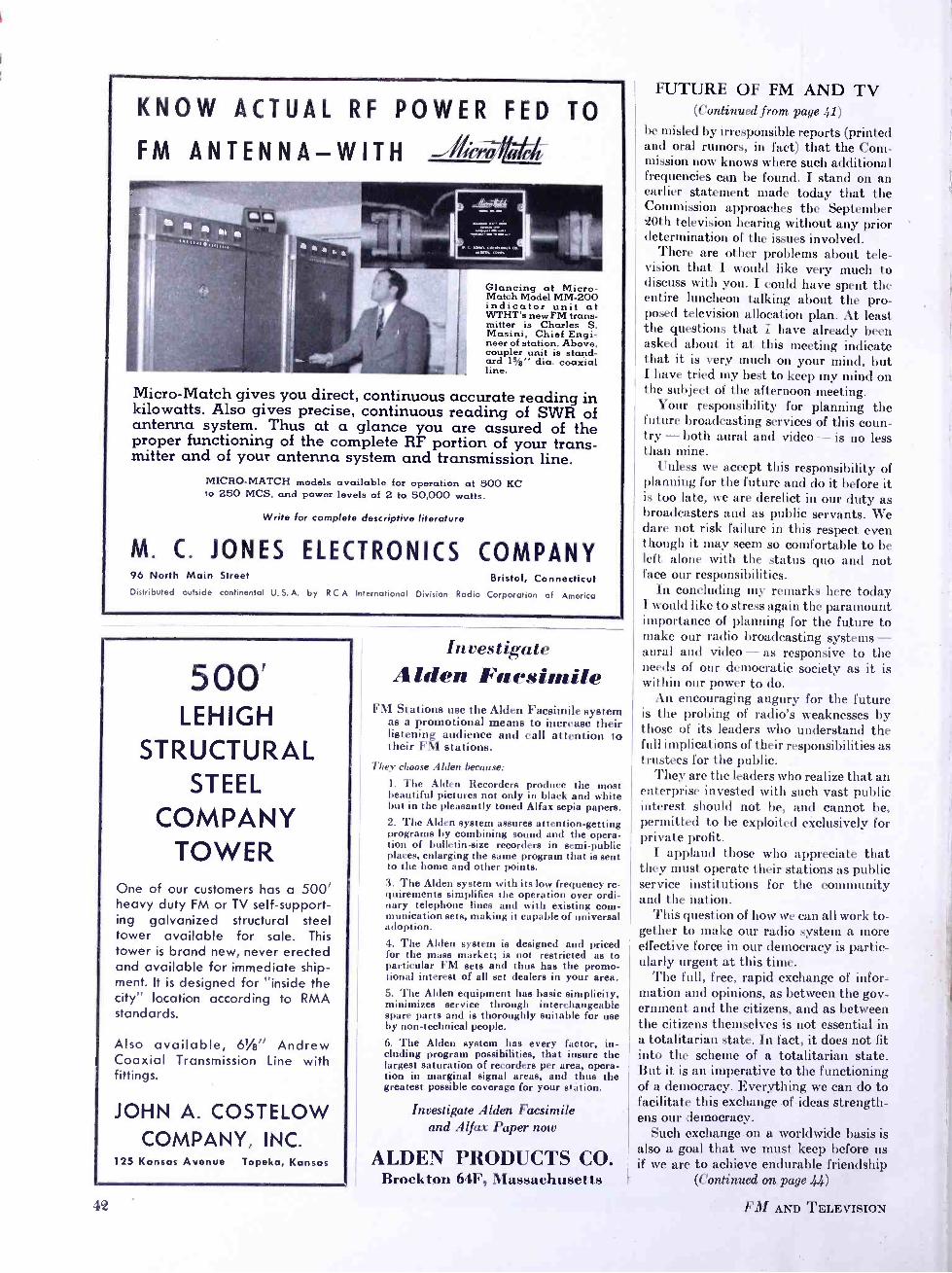
KNOW ACTUAL RF POWER FED TO
FM ANTENNA -WITH ala
Glancing at Micro - Match Model MM -200 indicator unit at WTHT's new FM trans- mitter is Charles S. Masini, Chief Engi- neer of station. Above, coupler unit is stand- ard 15 /e" dia. coaxial line.
Micro -Match gives you direct, continuous accurate reading in kilowatts. Also gives precise, continuous reading of SWR of antenna system. Thus at a glance you are assured of the proper functioning of the complete RF portion of your trans- mitter and of your antenna system and transmission line.
MICRO -MATCH models available for operation at 500 KC to 250 MCS, and power levels of 2 to 50,000 watts.
Write for complete descriptive literature
M. C. JONES ELECTRONICS COMPANY 96 North Main Street Bristol, Connecticut Distributed outside continental U.S.A. by RCA International Division Radio Corporation of America
500' LEHIGH
STRUCTURAL STEEL
COMPANY TOWER
One of our customers has a 500' heavy duty FM or TV self- support- ing galvanized structural steel tower available for sale. This tower is brand new, never erected and available for immediate ship- ment. It is designed for "inside the city" location according to RMA standards.
Also available, 61/4'' Andrew Coaxial Transmission Line with fittings.
JOHN A. COSTELOW COMPANY, INC.
125 Kansas Avenue Topeka, Kansas
l.
Investigate Alden Facsimile
FM Stations use the Alden Facsimile system as a promotional means to increase their listening audience and call attention to their FM stations.
l bey choose Alden because:
1. The Alden Recorders produce the most beautiful pictures not only in black and white but in the pleasantly toned Alfax sepia papers. 2. The Alden system assures attention -getting programs by combining sound and the opera- tion of bulletin -size recorders in semi -public places, enlarging the same program that is sent to the home and other points. 3. The Alden system with its low frequency re- quirements simplifies the operation over ordi- nary telephone lines and with existing com- munication sets, making it capable of universal adoption. 4. The Alden system is designed and priced for the mass market; is not restricted as to particular FM sets and thus has the promo- tional interest of all set dealers in your area. 5. The Alden equipment has basic simplicity, minimizes service through interchangeable spare parts and is thoroughly suitable for use by non -technical people.
6. The Alden system has every factor, in- cluding program possibilities, that insure the largest saturation of recorders per area, opera- tion in marginal signal areas, and thus the greatest possible coverage for your station.
Investigate Alden Facsimile and Alfax Paper now
ALDEN PRODUCTS CO. Brockton 64F, Massachusetts
FUTURE OF FM AND TV (Continued from page .41)
be misled by irresponsible reports (printed and oral rumors, in fact) that the Com- mission now knows where such additional frequencies can be found. I stand on an earlier statement made today that the Commission approaches the September 20th television hearing without any prior determination of the issues involved.
There are other problems about tele- vision that I would like very much to discuss with you. I could have spent the entire luncheon talking about the pro- posed television allocation plan. At least the questions that I have already been asked about it at this meeting indicate that it is very much on your mind, but I have tried my best to keep my mind on the subject of the afternoon meeting.
Your responsibility for planning the future broadcasting services of this coun- try - both aural and video - is no less than mine.
Unless we accept this responsibility of planning for the future and do it before it is too late, we are derelict in our duty as broadcasters and as public servants. We dare not risk failure in this respect even though it may seem so comfortable to be left alone with the status quo and not face our responsibilities.
In concluding my remarks here today I would like to stress again the paramount importance of planning for the future to make our radio broadcasting systems - aural and video - as responsive to the needs of our democratic society as it is within our power to do.
An encouraging augury for the future is the probing of radio's weaknesses by those of its leaders who understand the full implications of their responsibilities as trustees for the public. .
They are the leaders who realize that an enterprise invested with such vast public interest should not be, and cannot be, permitted to be exploited exclusively for private profit.
I applaud those who appreciate that they must operate their stations as public service institutions for the community and the nation.
This question of how we can all work to- gether to make our radio system a more effective force in our democracy is partic- ularly urgent at this time.
The full, free, rapid exchange of infor- mation and opinions, as between the gov- ernment and the citizens, and as between the citizens themselves is not essential in a totalitarian state. In fact, it does not fit into the scheme of a totalitarian state. But it is an imperative to the functioning of a democracy. Everything we can do to facilitate this exchange of ideas strength- ens our democracy.
Such exchange on a worldwide basis is also a goal that we must keep before us if we are to achieve endurable friendship
(Continued on page 44)
FM AND TELEVISION

,L:nA FM Sets... Syha..ia Lock -In Tubes ...
handle emergency calls rapidly and
smoothly for Morro Limousine
2 -way radio permits drivers to notify central office of completion of trip.
Office can immediately ad-
vise driver of other calls in the some neighborhood.
WITH 10 of its 14 limousines equipped with 2 -way Link FM, Morro Limousine Service is
always ready -24 hours a day -to respond promptly to emergency calls for home -to- hospital transporta- tion- anywhere in the entire Borough of Brooklyn. Cars are strategically located throughout the borough, to reach any point in the shortest possible time.
Since quick, unfailing service is the essence of
Morro Limousine's business, Link Radio Corporation turns to Sylvania Lock -In Tubes to prevent com- munications interruptions. These tubes stay firmly in
place in their sockets ... have no soldered joints, few
welded ones. Elements can't warp or weave. Con- nections are short and direct ... getter located on top. Loss and leakage are reduced. See Sylvania Distribu- tors or write Radio Tube Division, Emporium, Pa.
SYLYANIAvI Lt CT III C
Transmitting and Receiving Units used by MOrro Limousine Service, manufactured by Link Radio Cor- poration, New York.
The famous Lock -In Tube's superiority makes it the ideal choice for equipment on the road, in the air, on the rails, marine radar, FM and television.
MAKERS OF RADIO TUBES; CATHODE RAY TUBES; ELECTRONIC DEVICES; FLUORESCENT LAMPS, FIXTURES, WIRING DEVICES; ELECTRIC LIGHT BULBS
June 1948 - formerly VII, and FM ß aneo- ELEcTROwics ' 43
WASH FM WASHington, D. C.
ORIGINATING STATION
FOR THE
Contimadat 91f2fw.ofilt.
WASH - FM now broadcasts all WASHINGTON SENATORS
Weekday Baseball Games and features a host of other outstanding live talent shows for
GOOD LISTENING ON FM!
Since 1945
"Featuring the Finest in Musical Entertainment"
EVERETT L. DILLARD, General Manager
WMRC -FM GREENVILLE, S. C.
STILL WIDER COVERAGE: 62% more power on the permanent frequency of 94.9 mc. now gives WMRC -FM listeners still finer entertainment service
With 79,000 watts of effective radiation on 94.9 mc.,
WMRC -FM has taken the lead in providing fine programs with powerful signals over the western and central Carolinas and east to Rocky Mount, Goldsboro, Fayette- ville, Myrtle Beach, and Charleston, and extending to
Bristol and Danville, Virginia, Knoxville and Johnson City, Tennessee, and Atlanta and Athens, Georgia. Daily
schedule, noon to 10:00 p.m.
Textile Broadcasting Co. WMRC and WMRC -FM
11
FUTURE OF FM AND TV (Continued from page 4e)
and understanding among the nations of the world.
While we are striving towards this goal through our diplomatic activities, let us consider what we can do here at home.
Like many other Americans, I have often pondered on the mystery of how totalitarian regimes could find any ac- ceptance among their masses of people. Such philosophies of government seem so anachronistic, so brutal, so cynical, and so completely contrary to all American traditions of freedom and respect for the individual that I have found it difficult to comprehend any tolerance of them even in extremities of desperation. And yet we have seen the growth of this evil in far too many places around the globe: We have seen the pattern repeated too often. Even today after all the blood and treasure poured into World War II, the spirit of dictatorship is ascendant in many parts of the world.
In today's turbulence, America stands as a bulwark of democracy. We must do everything we can to keep it that way. We must hold on to the democratic gains we have made through the years.
We must strengthen and perfect our society as much as possible to meet the dangers of today and the threats of the future. By now we Americans have had enough examples to see beyond the per- adventure of a doubt that the way for us to meet the future is not to think of re- stricting our democratic process but to expand it to the fullest measure and to take every precaution to see that it func- tions vigorously on behalf of all the people.
In our effort to make this nation a more complete democracy by bringing the groups of people closer to each other and by bringing the people and their govern- ment closer together, no instrumentality can play a more powerful role than our broadcasting industry. With the vastly augmented facilities which are available, you broadcasters can dwarf your former great achievements in this field.
We are fortunate in having this new era of broadcasting just at a time when the complexities of our community, na- tional and international problems de- mand a greater degree of intelligent con- sideration and participation of our citi- zens than ever before.
Before I close, I would like to emphasize one fact:
I know of no responsible person in the government, including members and staff of the Federal Communications Commis- sion, who favors government operation of broadcasting.
I am sure that the one unanimous deci- sion that the members of the FCC could reach is that, generally speaking, broad- casting in the United States operates in the public interest.
(Concluded on page 46)
FM AND TELEVISION
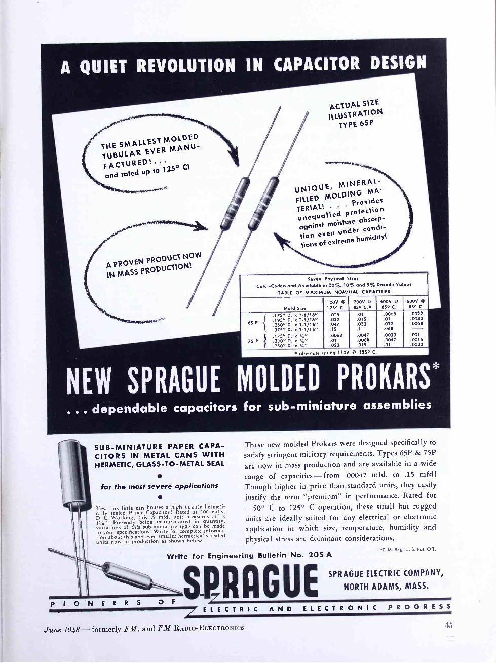
A QUIET REVOLUTION IN CAPACITOR DESIGN
THE SMALLEST MOLDED
TUBULAR EVER MANU-
FACTURED!. and rated up to 125
o C
UNIQUE, MINERAL -
FILLED MOLDING MA-
TERIAL! Provides rotection unequalled p
absorp-
tion moisture
even under condi-
tions of extreme humidity!
Seven Physical Sizes
Color -Coded and Available in 20%, 10% and 5% Decade Values
TABLE OF MAXIMUM NOMINAL CAPACITIES
to*****'-
Mold Size
65 P
75 P
i
I
.175" D. x 1-1/16"
.195" D. x 1-1/16"
.250" D. x 1-1/16"
.375" D. x 1-1/16"
.175" D. x 3/4"
.200" D. x 3/4"
.250" D. x 3/4"
100V @
125° C.
.015 .022 .047 .15 .0068 .01 .022
200V @
85° C.+
.01
.015
.033
.1
.0047
.0068 .015
* alternate rating 150V @ 125° C.
400V @
85° C.
.0068
.01 .022 .068 .0033 .0047 .01
85° C.
.0022
.0033
.0068
.001
.0015 .0033
NEW SPRAGUE MOLDED PROKARS*
... dependable capacitors for sub - miniature assemblies
SUB- MINIATURE PAPER CAPA- CITORS IN METAL CANS WITH HERMETIC, GLASS -TO -METAL SEAL
for the most severe applications
Yes, this little can houses a high quality hermeti- cally sealed Paper Capacitor! Rated at 100 volts, D C Working, this .5 mfd. unit measures .4" x
It /g ". Presently being manufactured in quantity, variations of this sub -miniature type can be made to your specifications. Write for complete informa- tion about this and even smaller hermetically sealed units now in production as shown below.
Write for
P I O N R
These new molded Prokars were designed specifically to
satisfy stringent military requirements. Types 65P & 75P
are now in mass production and are available in a wide
range of capacities -from .00047 mfd. to .15 mfd!
Though higher in price than standard units, they easily
justify the term "premium" in performance. Rated for
-50° C to 125° C operation, these small but rugged
units are ideally suited for any electrical or electronic
application in which size, temperature, humidity and
physical stress are dominant considerations. *T. M. Reg. U. S. Pat. Off.
Engineering Bulletin No. 205 A
S.RACUET E L E C T R I C A N D E L E C T R O N I C P R O G R E S S
SPRAGUE ELECTRIC COMPANY,
NORTH ADAMS, MASS.
June 1948 - formerly FM, and FM RADIO -ELECTRONICS -43
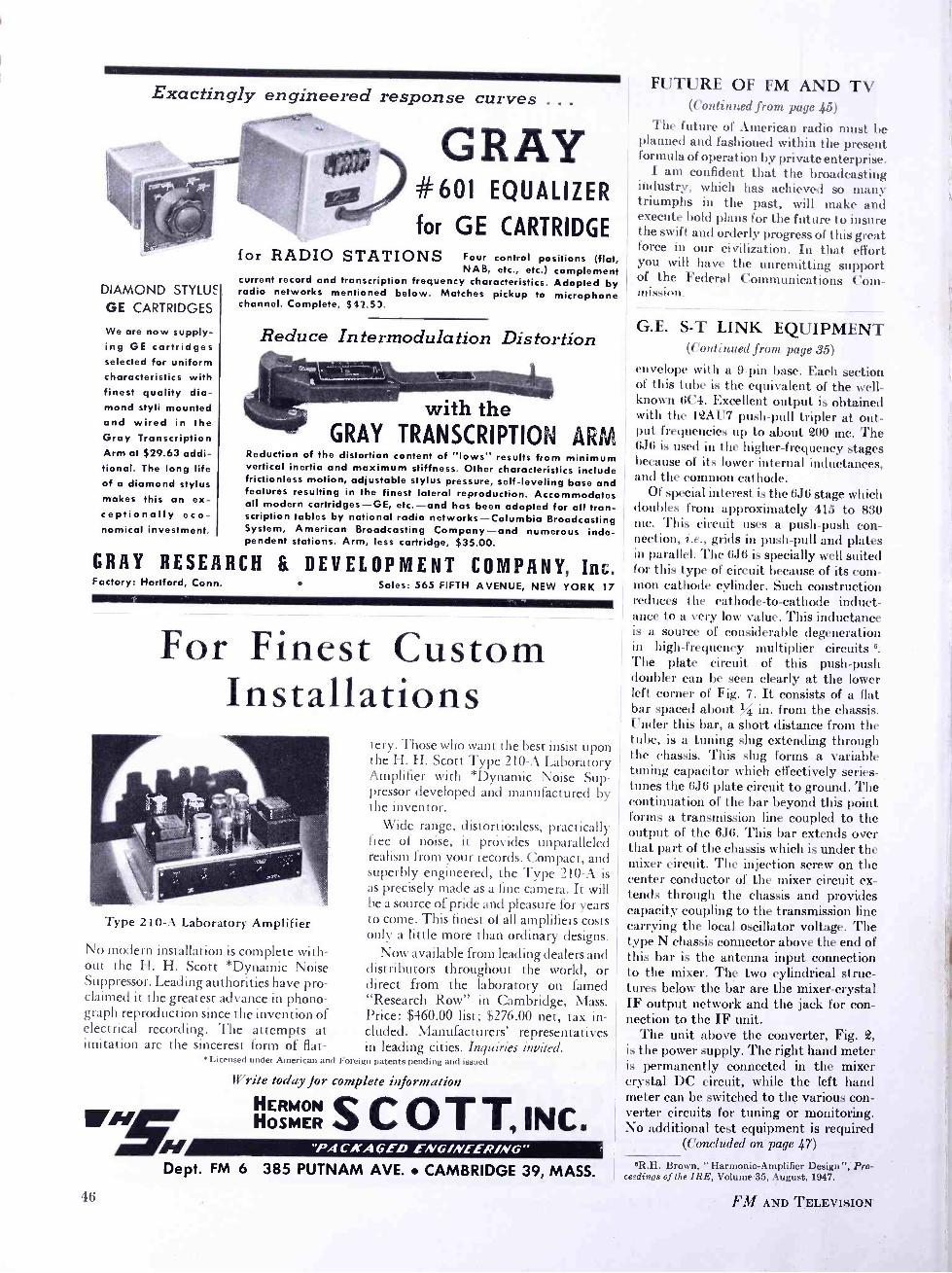
Exactingly engineered response curves ...
DIAMOND STYLUS
GE CARTRIDGES
We are now supply- ing GE cartridges selected for uniform characteristics with finest quality dia- mond styli mounted and wired in the Gray Transcription Arm at $29.63 addi- tional. The long life of o diamond stylus makes this an ex- ceptionally eco- nomical investment.
GRAY
for RADIO
GRAY #601 EQUALIZER
for GE CARTRIDGE STATIONS Four control positions (flat,
NAB, etc., etc.) complement current record and transcription frequency characteristics. Adopted by radio networks mentioned below. Matches pickup to microphone channel. Complete, $ 12.53.
Reduce In termodula tion Distortion
with the GRAY TRANSCRIPTION ARM
Reduction of the distortion content of "lows" results from minimum vertical inertia and maximum stiffness. Other characteristics include frictionless motion, adjustable stylus pressure, self -leveling base and features resulting in the finest lateral reproduction. Accommodates all modern cartridges -GE, etc. -and has been adopted for all tran- scription tables by national radio networks -Columbia Broadcasting System, American Broadcasting Company -and numerous inde- pendent stations. Arm, less cartridge, $35.00.
RESEARCH & DEVELOPMENT COMPANY, Ins. Factory: Hartford, Conn. Sales: 565 FIFTH AVENUE, NEW YORK 17
For Finest Custom Installations
Type 210 -A Laboratory Amplifier
No modern installation is complete with- out the H. H. Scott *Dynamic Noise Suppressor. Leading authorities have pro- claimed it the greatest advance in phono- graph reproduction since the invention of electrical recording. The attempts at imitation are the sincerest form of flat-
/5/
tery. "Those who want the best insist upon the H. H. Scott Type 210 -A Laboratory Amplifier with *Dynamic Noise Sup- pressor developed and manufactured by the inventor.
Wide range, distortionless, practically free of noise, it provides unparalleled realism from your records. Compact, and superbly engineered, the Type 210 -A is as precisely made as a fine camera. It will be a source of pride and pleasure for years to come. This finest of all amplifiers costs only a little more than ordinary designs.
Now available from leading dealers and distributors throughout the world, or direct from the laboratory on famed "Research Row" in Cambridge, Mass. Price: $460.00 list; $276.00 net, tax in- cluded. Manufacturers' representatives in leading cities. Inquiries invited.
*Licensed under American and Foreign patents pending and issued
Write today for complete information
HOSMER SCOT T, iNC t. "PA CKAGED ENG /NEER /NG"
Dept. FM 6 385 PUTNAM AVE. CAMBRIDGE 39, MASS.
I(;
FUTURE OF FM AND TV (Conti 'rued from page 45)
The future of American radio must be planned and fashioned within the present formula of operation by private enterprise.
I am confident that the broadcasting industry, which has achieved so many triumphs in the past, will make and execute bold plans for the future to insure the swift and orderly progress of this great force in our civilization. In that effort you will have the unremitting support of the Federal Communications Com- mission.
G.E. S -T LINK EQUIPMENT (cont, rrued from page 35)
envelope with a 9 -pin base. Each section of this tube is the equivalent of the well - known 6C4. Excellent output is obtained with the 12AU7 push -pull tripler at out- put frequencies up to about 200 mc. The 6J6 is used in the higher- frequency stages because of its lower internal inductances, and the common cathode.
Of special interest is the 6J6 stage which doubles from approximately 415 to 830 mc. This circuit uses a push -push con- nection, i.e., grids in push -pull and plates ill parallel. The 6J6 is specially well suited for this type of circuit because of its com- mon cathode cylinder. Such construction reduces the cathode -to- cathode induct- ance to a very low value. This inductance is a source of considerable degeneration ill high- frequency multiplier circuits 6.
The plate circuit of this push -push doubler can be seen clearly at the lower left corner of Fig. 7. It consists of a flat bar spaced about % in. from the chassis. tinder this bar, a short distance from the tube, is a tuning slug extending through the chassis. This slug forms a variable tuning capacitor which effectively series - tunes the 6J6 plate circuit to ground. The continuation of the bar beyond this point forms a transmission line coupled to the output of the 6J6. This bar extends over that part of the chassis which is under the mixer circuit. The injection screw on the center conductor of the mixer circuit ex- tends through the chassis and provides capacity coupling to the transmission line carrying the local oscillator voltage. The type N chassis connector above the end of this bar is the antenna input connection to the mixer. The two cylindrical struc- tures below the bar are the mixer- crystal IF output network and the jack for con- nection to the IF unit.
The unit above the converter, Fig. 2, is the power supply. The right hand meter is permanently connected in the mixer crystal DC circuit, while the left hand meter can be switched to the various con- verter circuits for tuning or monitoring. No additional test equipment is required
(Concluded on page 47)
ÔR.H. Brown, " Harmonic -Amplifier Design "; Pro- ceedings of the IRE, Volume 35, August, 1947.
FM AND TELEVISION

G.E. S -T LINK EQUIPMENT (font i n ued from page 46)
to tune the receiver to any frequency in the 920- to 960 -mc. range.
The IF unit is shown below the convert- er. Referring to the block diagram, the two 11e -inc. first IF stages are of the cathode -coupled, double- triode type. These two stages provide sufficient second IF image rejection and a good noise figure for the IF unit. The second converter is
crystal controlled from an overtone (triplex) crystal operating at about 20 mc. This frequency is tripled in the plate cir- cuit of the oscillator and doubled in a buffer before injection into the second con- verter. Three stages of 10.7 -mc. second IF provide enough gain to give limiting on input circuit noise.
Adjacent -channel selectivity of better than 80 db has been measured. Two cas- cade limiters precede the discriminator. The signal strength meter shown on the left side of the unit indicates first limiter grid current. Separate screwdriver con- trols provide gain adjustment of both first and second IF sections.
The signal strength meter provides a means of aiming the directive antenna and tuning the first converter crystal mixer circuit for maximum signal. The zero - center tuning meter on the right side of the unit is connected to the balanced dis- criminator, and provides a means of setting the trimmer on the first converter Thermocell crystal. A change of center frequency in either the transmitter or re ceiver will be indicated by this meter. Two stages of low -distortion audio provide the rated output of + 18 dbm for ± 75 -kc. deviation. The measured overall harmonic distortion of the transmitter and receiver together is shown in Fig. 8. This curve shows a considerable safety factor between the maximum value in the specification and the results measured on the developmental system.
Acknowledgment: It must be recognized that many in- dividuals contributed to the design of this equipment. Acknowledgment should be given particularly to the work of H. P. Thomas on the electrical design of the transmitter and overall system, and to R. A. Lash and W. R. Fraser for the mechanical designs. These engineers are all members of the G.E. transmitter division.
FMA CONVENTION Big plans are being made by broad-
casters and set manufacturers for the FM Association's national convention in Chi- cago, September 27 to 29. Meetings that concern FM have always been exception- ally well attended. This should be no ex- ception, for there will be over 700 FM stations on the air in September. Program and the exhibits will be extremely inter- esting.
ADV[RTIS[RS INDEX Adair, George P. 3, 17
Alden Products Company 42 Altec Lansing Corp. 41 Amy, Aceves & King, Inc. 16 Andrew Corporat ion 6, 12
Barone, S. A., Company 13
Bell Telephone Labs 9, 14 Blaw -Knox 1
Boonton Radio Corp. 41 Brociner Elect. Lab. 8
Browning Laboratories, Inc. 5
Collins Audio Products 39 Commercial Radio Equip. Co. 13 Costelow, John A., Co., Inc. 42
Davis, George C. 13
DeMars, Paul A 12
Eitel- McCullough, Inc. 48 Electronics Research Pub. Co. 8
Federal Tel. & Radio Corp. 10, 11
Garrard Sales Corp. 47 Gray Research & Develop. Co 46 Graybar Electric Co. 9, 14
Harvey Radio Labs., Inc. Inside Front Cover Hughey & Phillips Company 8
Jansky & Bailey 12
Jones Electronics Co. 42
Karp Metal Products Co Cover III Kear and Kennedy 13
Knights Co., The James 4
Mallory & Co., Inc., P. R. 40 May, Russell P. 12
McCachren, Winfield Scott 13
McIntosh, Frank H. 13 McKey, Dixie B. & Assoc. 12
McNary and Wrathall 13
Pollack, Dale 12
Radio Consultants, Inc. 13
Radio Corp. of America 24, 25 Radio Engineering Labs. Inc.... Back Cover Ray, Garo W. 12 Raytheon Mfg. Co 2
Rider, John F. 38
Sangamo Electric Co. 37 Scott, Inc., H. H. 46 Smeby, Lynne C. 12
Sprague Electric Co. 45 Surprenant Mfg. Co. 39 Sylvania Electric 43
Topflight Tape Co.
U. S. Recording Co.
Vesto Co., The
WASH -FM Weldon & Carr 'Western Electric Co. Williams, Nathan Wilmotte, Raymond M. WMRC -FM Workshop Associates, The
June 1948 - formerly FM, and FM RADIO -ELECTRONICS
8
18
39
44 13
9, 14 12 12 44
7, 8
\\'`.
GARRARD s RECORD CHANGER
Easily recognized - distinctive
in appearance ... its presence
in a radio phonograph indicates
the superlative quality of the
entire instrument.
Available in two models
world's finest automatic
RC65 - FOR HIGHER -PRICED SETS
A radically improved Mixer- Changer with many exclusive features. Trouble - free motor with speed -regulator, goy -
ernor -controlled. Positive automatic stop. Reject lever. True -tangent pick-
/,-, up with boll -bearing, jewelled mount
and pivot. Patented non -slip spindle. Specially designed "floating springs" for mounting changer.
i<
RC70 - FOR MODERATE- PRICED SETS
7/2
Simplicity combined with usual Garrard high engineering standards. New -type pusher platform guarantees gentle handling of records. Plays ten
10 " -12" records. Turntable weighted for fly -wheel action, driven by drum on inside. Start, Stop and Reject lever combined. Removable center spindle. New parallel lift tone arm guarantees true tangent tracking.
Write for descriptive literature to
Dept. F - Garrard Sales Corp.
315 Broadway, New York 7, N. Y.
47

FREQUENCY UP 6X, (156.75 -Mc. to 940.5 -Mc.) POWER UP 7X (2 watts to 15 watts)
Here's a STL transmitter that's in operation on the new 950 -Mc. band, fulfilling all the FCC requirements and pow- ered by Eimac 4X150A tetrodes. It's a part of the studio - transmitter -link between the San Bruno studios and the 250 Kw FM transmitter of station KSBR high atop 3849 -foot Mt. Diablo some 33 miles away.
REL
MODULATOR
2 WATTS
156.75 -Mc.
EIMAC 4X150A IS WAT TS
TRIPLER 470.25-Mc
EIMAC 4X150A IS WATTS
DOUBLER 940 5-Mc.
The R -F amplifier was specifically designed for the KSBR application by Eimac engineers. It is driven by an REL modu- lator delivering 2 watts output at 156.7 -Mc. to one Eimac 4X150A in a tripler stage, which in turn drives a single 4X150A in a doubler stage, providing 15 watts useful output at 940.5 -Mc.
The Eimac 4X150A is ideally suited for this application be- cause of its high power gain at relatively low plate voltages, ability as a frequency multiplier without loss of amplification, low grid drive requirements, and a high ratio of transconduc- tance to capacitance. It also has the advantage of being phys- ically small and functionally designed for simple installation.
Complete data on the Eimac 4X150A for STL and other UHF applications is available by writing direct.
EITEL_McCULLOUGH, INC. 197 San Mateo Avenue, San Bruno, California
EXPORT AGENTS: Frazar & Hansen -301 Clay St. -San FroncTsco, Calif.
4X150A
ESSENTIAL DATA KSBR STL TRANSMITTER
REL MODULATOR, MODEL 694 EIMAC 4X150A, R -F AMPLIFIER
Useful Output Power Frequency Frequency Stability Audio Frequency Response.
Substantially flat - - - - 50 to 15,000 cycles Distortion .5% Max. Noise Level - 70 db below 100% modulation t 100 Kc. deviation
15 watts 940.5 Mc.
.002%
Eimac 4X1 50A General Characteristics
Heater voltage Heater current Minimum heating time Grid Screen amplification factor - - - - 4.5 Direct interelectrode capacitance (Average)
Grid -Plate Input Output
6.0 volts 2.8 amps. 30 secs.
Maximum Ratings D -C Plate voltage D -C Plate current Plate dissipation D -C Screen voltage
0.02 Auf 14.1 ppf 4.7 Nk,f
1000 volts 250 ma. 150 watts 300 volts
Follow the Leaders to
ES The Power for R-F
48 FM AND TELEVISION
We've got our eye on amour
assembly line ... to help you speed production
PUMFORD PRESS CONCORD. N. H.
r "? %/I,^
When we build cabinets, housings or enclosur, for and cleanly drilled, all openings precisely spaced,
you, we plan and work with the objective of saving all welding skillfully done with finest equipment.
you time, labor and extra operations on your
duction line. pro -
As a result, in your assembling, all functional parts, 1 instruments and controls will fit correctly and easily
Karp -constructed units are handsome and stream-
lined, but their beauty is more than skin deep. The
extra value our work affords is a degree of quality, accuracy and precision that will speed up your assembling operations.
You will find all units completely uniform in every
detail, all measurements exact, all holes the right size
into place. Installation operations will be smooth
and speedy You will encounter no delays for any
completion details. This saving of time and labor will cut your costs. Your completed assemblies will have added market value, too. In short, Karp cus-
tom craftsmanship will prove less expensive in the
long run. d
KARP METAL PRODUCTS CO., INC. 126 30th STREET, BROOKLYN 32, NEW YORK
Wild494/2 ( e2 gitE e

REL MODEL 694 As might be expected from REL's leadership in
the development of the FM art and in particular in the advancement of FM broadcasting, REL again leads the
field by presenting its most the industry.
recent achievement to
This development is the result of many months of research. It is presented in answer to increasing demands for equipment to link
studio and transmitter with very great fidelity and without the use of wire lines. The suc-
cess of this development is measured in terms of equipment which will in no
way contribute to the noise, distor- tion, or audio limitations of
the overall system.
FM
TRANSMITTER SECTION OF THE MODEL 694
oar
Nt, u;
FREQUENCY: 940 to 960 mega- cycles.
RANGE: To be employed between positive line of sight points and, in no' case, over a path in excess of thirty miles.
EQUIPMENT INCLUDES: Transmitter, 10db gain Transmitting antenna, Receiver, One set of oper- ating tubes and crystals.
ADDITIONAL EQUIPMENT OPTIONAL: 40 foot supporting structures for transmitting and receiving antennas; Higher gain transmitting and receiving antennas; Transmission lines and fittings.
0
RECEIVER SECTION OF
THE MODEL 694
ELECTRICAL PERFORMANCE AUDIO RESPONSE: 0.3 DB FROM 50 TO 15,000 CYCLES
SIGNAL TO NOISE RATIO: 75 DB
BELOW 100 % MODULATION. (TRANSMITTER INPUT TO RECEIVER
OUTPUT. DOES NOT INCLUDE SPACE ATTENUATION.)
DISTORTION: NO GREATER THAN 0.3 % AT 100 % MODULATION THROUGHOUT THE AUDIO RANGE FROM 50 TO 15,000 CYCLES.
TRANSMITTER POWER OUTPUT: 15 WATTS.
RADIO ENGINEERING LABS. INC., LONG ISLAND CITY 1, N. Y.