prexiso t.o - opti-cal survey equipment ltd · 2014-07-30 · introduction t.o.2 | 3 symbols the...
TRANSCRIPT
PREXISO T.O.2
User ManualVersion 1.0

T.O.2 | 2Introduction
Introduction
Purchase Congratulations on the purchase of a T.O.2 instrument.
This manual contains important safety directions as well as instructions for setting up the product and operating it. Refer to "7 Safety Directions" for further information.Read carefully through the User Manual before you switch on the product.
Product identifica-tion
The type and serial number of your product are indicated on the type plate. Enter the type and serial number in your manual and always refer to this information when you need to contact your agency or PREXISO authorised service workshop.
Type: ______________________________________________
Serial No.: ______________________________________________
Introduction T.O.2 | 3
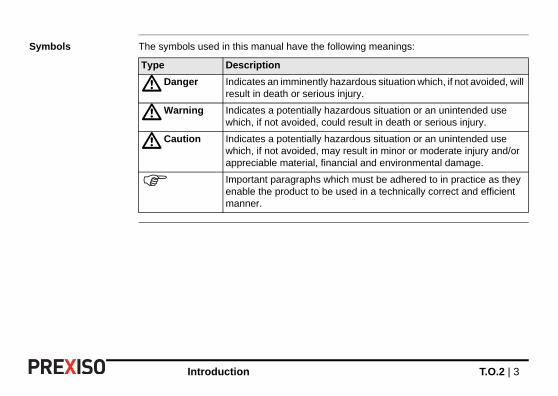
Symbols The symbols used in this manual have the following meanings:
Type Description
�Danger Indicates an imminently hazardous situation which, if not avoided, will result in death or serious injury.
�Warning Indicates a potentially hazardous situation or an unintended use which, if not avoided, could result in death or serious injury.
�Caution Indicates a potentially hazardous situation or an unintended use which, if not avoided, may result in minor or moderate injury and/or appreciable material, financial and environmental damage.
Important paragraphs which must be adhered to in practice as they enable the product to be used in a technically correct and efficient manner.
T.O.2 | 4Table of Contents
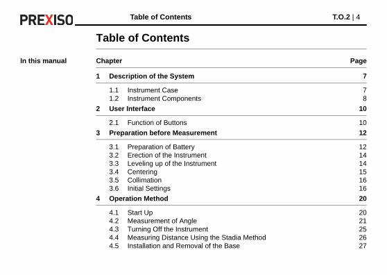
Table of Contents
In this manual Chapter Page
1 Description of the System 7
1.1 Instrument Case 71.2 Instrument Components 8
2 User Interface 10
2.1 Function of Buttons 10
3 Preparation before Measurement 12
3.1 Preparation of Battery 123.2 Erection of the Instrument 143.3 Leveling up of the Instrument 143.4 Centering 153.5 Collimation 163.6 Initial Settings 16
4 Operation Method 20
4.1 Start Up 204.2 Measurement of Angle 214.3 Turning Off the Instrument 254.4 Measuring Distance Using the Stadia Method 264.5 Installation and Removal of the Base 27
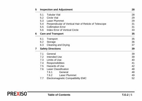
Table of Contents T.O.2 | 5
5 Inspection and Adjustment 28
5.1 Tubular Vial 285.2 Circle Vial 295.3 Laser Plummet 295.4 Perpendicular of Vertical Hair of Reticle of Telescope 315.5 Collimation Error 315.6 Index Error of Vertical Circle 33
6 Care and Transport 35
6.1 Transport 356.2 Storage 366.3 Cleaning and Drying 37
7 Safety Directions 39
7.1 General 397.2 Intended Use 397.3 Limits of Use 407.4 Responsibilities 417.5 Hazards of Use 427.6 Laser Classification 48
7.6.1 General 487.6.2 Laser Plummet 49
7.7 Electromagnetic Compatibility EMC 52

T.O.2 | 6Table of Contents
8 Technical Data 55
9 International Limited Warranty 57
10 Accessories 58
11 Error Information 59

Description of the System T.O.2 | 7
1 Description of the System
1.1 Instrument Case
Instrument case Before placing the instrument into the instrument case, align the dot mark of the instrument upward and on the same line, and lightly tighten the clamp knobs and loosened after the instru-ment is placed in the case. All the clamp knobs must be slightly tightened again after the instrument is in place in the case.
T.O.2 | 8Description of the System
1.2 Instrument Components
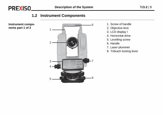
Instrument compo-nents part 1 of 2
1. Screw of handle2. Objective lens3. LCD display I4. Horizontal drive5. Levelling screw6. Handle7. Laser plummet8. Tribrach locking lever
6
7
85
4
3
2
1
Description of the System T.O.2 | 9
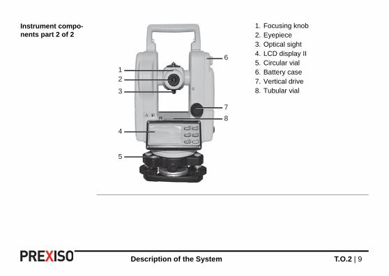
Instrument compo-nents part 2 of 2
1. Focusing knob2. Eyepiece3. Optical sight4. LCD display II5. Circular vial6. Battery case7. Vertical drive8. Tubular vial
21
3
4
5
6
7
8

T.O.2 | 10User Interface
2 User Interface
2.1 Function of Buttons
Description
Buttons
1. R/L button2. HOLD button3. V% button4. 0SET button5. ON/OFF button6. Light button
1
3
5
2
4
6
Button Function 1 Other
ON/OFF Switch the instru-ment On/Off
1. One of the function buttons for entering into initial setting of the instrument.
2. One of the function buttons for entering into index error setting.
3. One of the function buttons for entering into compensation setting.
User Interface T.O.2 | 11
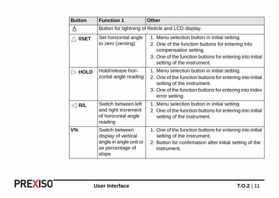
Button for lightning of Reticle and LCD display.
0SET Set horizontal angle to zero (zeroing)
1. Menu selection button in initial setting.2. One of the function buttons for entering into
compensation setting.3. One of the function buttons for entering into initial
setting of the instrument.
HOLD Hold/release hori-zontal angle reading
1. Menu selection button in initial setting.2. One of the function buttons for entering into initial
setting of the instrument.3. One of the function buttons for entering into index
error setting.
R/L Switch between left and right increment of horizontal angle reading
1. Menu selection button in initial setting.2. One of the function buttons for entering into initial
setting of the instrument.
V% Switch between display of vertical angle in angle unit or as percentage of slope
1. One of the function buttons for entering into initial setting of the instrument.
2. Button for confirmation after initial setting of the instrument.
Button Function 1 Other

T.O.2 | 12Preparation before Measurement
3 Preparation before Measurement
3.1 Preparation of Battery
Checking electric quantity
Refer to "4.1 Start Up" on how to check the power status of the battery.
Before removal of any battery, the instrument must be switched off to avoid malfunction.
Removal of AA-battery case
1. Turn the knob of the battery case and let
the mark point to UNLOCK, take the battery case off.
2. Open the case cover, insert four AA batteries into the battery case according to + and -.
Preparation before Measurement T.O.2 | 13
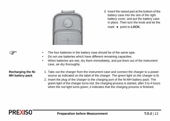
• The four batteries in the battery case should be of the same type.• Do not use batteries which have different remaining capacities.• When batteries are wet, dry them immediately, and put them out of the instrument
case, air-dry thoroughly.
Recharging the Ni-MH battery pack
1. Take out the charger from the instrument case and connect the charger to a power source as indicated on the label of the charger. The green light on the charger is lit.
2. Insert the plug of the charger to the charging port of the Ni-MH battery pack. The green light of the charger turns red, the charging process is started, after 3 to 4 hours when the red light turns green, it indicates that the charging process is finished.
3. Insert the raised part at the bottom of the battery case into the slot of the right battery cover, and put the battery case in place. Then turn the knob and let the
mark point to LOCK.
T.O.2 | 14Preparation before Measurement
3.2 Erection of the Instrument
Erection of the instrument
1. Stretch the tripod to a proper hight.2. Ensure that the measure point is exactly under the central hole of the tripod head.3. Level up the tripod (this is very important when centering with plumb bob).4. Ensure that all locking handles are securely tightened.5. Secure the instrument to the tripod.
3.3 Leveling up of the Instrument
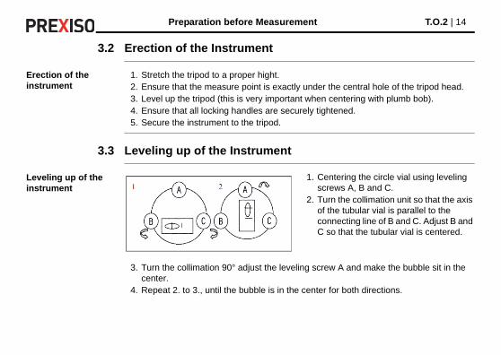
Leveling up of the instrument
3. Turn the collimation 90° adjust the leveling screw A and make the bubble sit in the center.
4. Repeat 2. to 3., until the bubble is in the center for both directions.
1. Centering the circle vial using leveling screws A, B and C.
2. Turn the collimation unit so that the axis of the tubular vial is parallel to the connecting line of B and C. Adjust B and C so that the tubular vial is centered.

Preparation before Measurement T.O.2 | 15
5. After 2. is finished, turn collimation unit for 180°. If the tubular vial is still centered, the leveling up of the instrument is finished. If the bubble strays from the center, perform leveling up with the procedure for adjustment of tubular vial in "5.1 Tubular Vial".
3.4 Centering
Centering with plumb bob
1. Tie the plumb bob wire to the hook on the central screw. Adjust the length of the wire so that the tip of the bob is 2 mm above ground.
2. Loosen the central screw and move the base so that the tip of the plumb bob is precisely positioned to the ground point (when observed from two directions perpen-dicular to each other).
Centering with Optical plummet
1. Turn the knob of the eyepiece of the optical plummet so that the reticle is in focus; turn the focusing knob so that the ground point a is in focus. Then, loosen the central screw
To ensure maximum measuring precision, we recommend the performance of the steps described in "5 Inspection and Adjustment" before using this instrument.a
1 2

T.O.2 | 16Preparation before Measurement
to translate the whole instrument (be sure not to turn the instrument) so that the ground point coincides with the central point of the reticle. Retighten the central screw.
2. Perform precise leveling up of the instrument as described in "3.3 Leveling up of the Instrument" and repeat the operation in 1. of "3.4 Centering", "Centering with Optical plummet" until the instrument is precisely leveled up and the center of the reticle of the optical plummet precisely coincides with the ground point as shown.
3.5 Collimation
Adjustment of diopter
1. Aim with the telescope on a bright background.2. Turn the eyepiece knob so that the cross hairs of the reticle are clearly seen.
Elimination of optical parallax
1. Adjust the focusing knob so that the object forms image on the reticle.2. Move your eyes up and down to see if the image of the object moves relative to the
graduation lines.If it does not move, there is no optical parallax; otherwise turn the focusing knob to eliminate the optical parallax.
3.6 Initial Settings
Before start measuring, please confirm all initial settings. Items in bold indicate factory settings.
Preparation before Measurement T.O.2 | 17
Method of setting
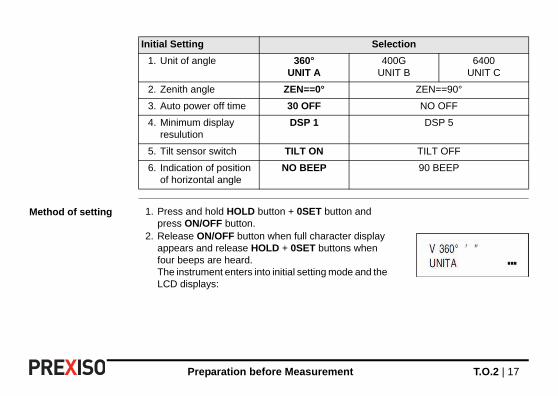
Initial Setting Selection
1. Unit of angle 360°UNIT A
400GUNIT B
6400UNIT C
2. Zenith angle ZEN==0° ZEN==90°
3. Auto power off time 30 OFF NO OFF
4. Minimum display resulution
DSP 1 DSP 5
5. Tilt sensor switch TILT ON TILT OFF
6. Indication of position of horizontal angle
NO BEEP 90 BEEP
1. Press and hold HOLD button + 0SET button and press ON/OFF button.
2. Release ON/OFF button when full character display appears and release HOLD + 0SET buttons when four beeps are heard.The instrument enters into initial setting mode and the LCD displays:
T.O.2 | 18Preparation before Measurement
Setting of items
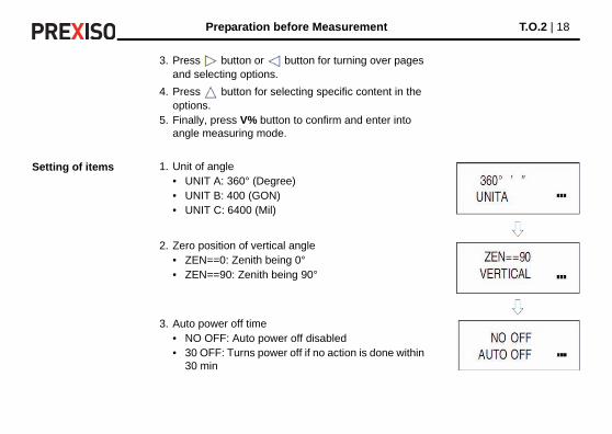
3. Press button or button for turning over pages and selecting options.
4. Press button for selecting specific content in the options.
5. Finally, press V% button to confirm and enter into angle measuring mode.
1. Unit of angle• UNIT A: 360° (Degree)• UNIT B: 400 (GON)• UNIT C: 6400 (Mil)
2. Zero position of vertical angle• ZEN==0: Zenith being 0°• ZEN==90: Zenith being 90°
3. Auto power off time• NO OFF: Auto power off disabled• 30 OFF: Turns power off if no action is done within
30 min
Preparation before Measurement T.O.2 | 19
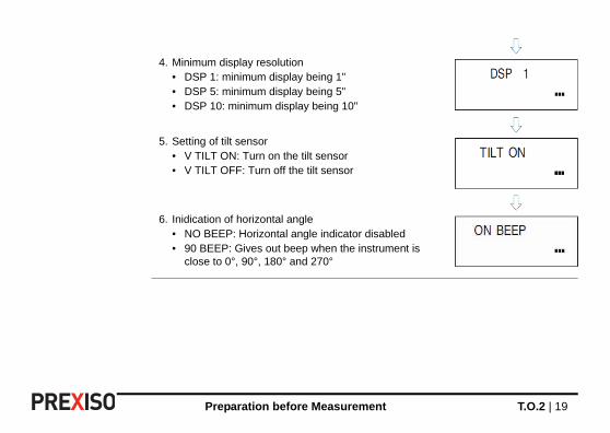
4. Minimum display resolution• DSP 1: minimum display being 1"• DSP 5: minimum display being 5"• DSP 10: minimum display being 10"
5. Setting of tilt sensor• V TILT ON: Turn on the tilt sensor• V TILT OFF: Turn off the tilt sensor
6. Inidication of horizontal angle• NO BEEP: Horizontal angle indicator disabled• 90 BEEP: Gives out beep when the instrument is
close to 0°, 90°, 180° and 270°
T.O.2 | 20Operation Method
4 Operation Method
4.1 Start Up
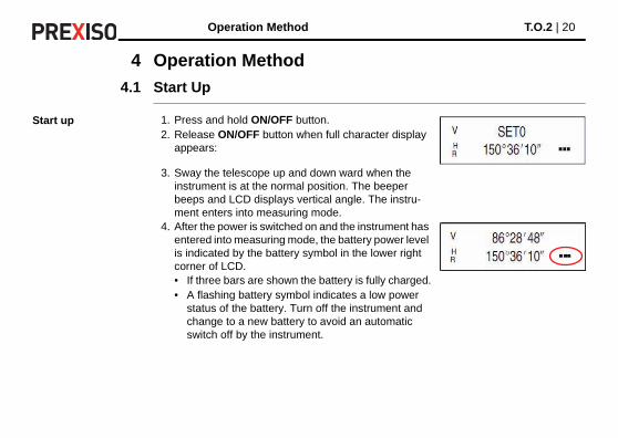
Start up 1. Press and hold ON/OFF button.2. Release ON/OFF button when full character display
appears:
3. Sway the telescope up and down ward when the instrument is at the normal position. The beeper beeps and LCD displays vertical angle. The instru-ment enters into measuring mode.
4. After the power is switched on and the instrument has entered into measuring mode, the battery power level is indicated by the battery symbol in the lower right corner of LCD.• If three bars are shown the battery is fully charged.• A flashing battery symbol indicates a low power
status of the battery. Turn off the instrument and change to a new battery to avoid an automatic switch off by the instrument.

Operation Method T.O.2 | 21
4.2 Measurement of Angle
Observing in the "Normal" and "Reverse" Positions of the Telescope
The normal position of the telescope refers to observation with the object lens facing right ahead (the vertical encoder being on the left); the reverse position refers to observation with the object lens facing right ahead (the vertical encoder being on the right). The mechanical errors can be offset by the average of the values of measured in the normal and reverse positions.
Normal Reverse
T.O.2 | 22Operation Method
Measurement of vertical angle
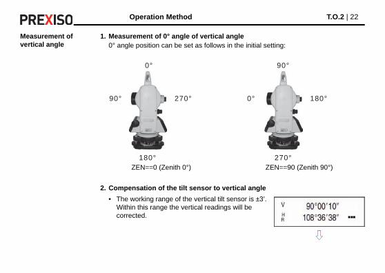
1. Measurement of 0° angle of vertical angle0° angle position can be set as follows in the initial setting:
2. Compensation of the tilt sensor to vertical angle
ZEN==0 (Zenith 0°) ZEN==90 (Zenith 90°)
• The working range of the vertical tilt sensor is ±3’. Within this range the vertical readings will be corrected.
0°
180°
90° 270°
90°
270°
0° 180°

Operation Method T.O.2 | 23
3. Display of slope
• If the inclination is greater than ±3’, the instrument will display as shown in the figure
Press V% button, the vertical angle display is turned into slope display; press V% button, the vertical angle display is resumed.
When vertical angle is turned into slope, the precision of slope is to the fourth digit after the decimal.The value of the slope is shown in the range of ±99.99% (±45°); outside of this range no value is displayed.

T.O.2 | 24Operation Method
Measurement of horizontal angle
1. Reset of horizontal angle
2. Selecting the direction of measurement of horizontal angle
3. Holding horizontal angle
Press 0SET button. The horizontal angle returns to zero.
Press R/L button to change the direction of measure-ment of horizontal angle.
• When HR is displayed, the angle increases with clockwise turning of the collimation unit.
• When HL is displayed, the angle increases with counter-clockwise turning of the collimation unit.

Operation Method T.O.2 | 25
4.3 Turning Off the Instrument
Turning off
Press HOLD button, the horizontal angle will be held; the reading of the horizontal angle will remain unchanged even if the direction of collimation is changed.
Press HOLD button again, the hold of horizontal angle is released.
1. Press ON/OFF button. OFF will be displayed at the position of vertical angle display after a beep.
2. Release ON/OFF button.The instrument is turned off.
T.O.2 | 26Operation Method
4.4 Measuring Distance Using the Stadia Method
Measuring distance using the Stadia method
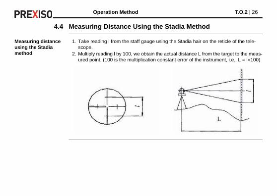
1. Take reading l from the staff gauge using the Stadia hair on the reticle of the tele-scope.
2. Multiply reading l by 100, we obtain the actual distance L from the target to the meas-ured point. (100 is the multiplication constant error of the instrument, i.e., L = l×100)

Operation Method T.O.2 | 27
4.5 Installation and Removal of the Base
Remove of the base
Installation of the base
1. Turn the screw on knob a outward using flat screw driver until it no more limits position.
2. Turn knob a counter-clockwise, holding the base with one hand and take the main body of the instrument off the base.
a
1. Turn the knob a counter-clockwise until it reaches the position limit.
2. Make the positioning block b on the main body of the instrument in line with the notch c on the base and install the main body onto the base as shown.
3. Turn the knob a clockwise until it
reaches the position limit so that the mark points downward.
4. Turn the screw until it can limit position.
b
c
T.O.2 | 28Inspection and Adjustment
5 Inspection and Adjustment
5.1 Tubular Vial
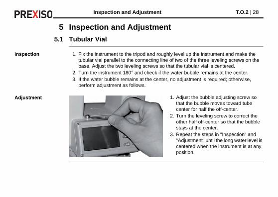
Inspection 1. Fix the instrument to the tripod and roughly level up the instrument and make the tubular vial parallel to the connecting line of two of the three leveling screws on the base. Adjust the two leveling screws so that the tubular vial is centered.
2. Turn the instrument 180° and check if the water bubble remains at the center.3. If the water bubble remains at the center, no adjustment is required; otherwise,
perform adjustment as follows.
Adjustment 1. Adjust the bubble adjusting screw so that the bubble moves toward tube center for half the off-center.
2. Turn the leveling screw to correct the other half off-center so that the bubble stays at the center.
3. Repeat the steps in "Inspection" and "Adjustment" until the long water level is centered when the instrument is at any position.
Inspection and Adjustment T.O.2 | 29
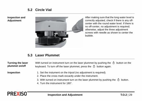
5.2 Circle Vial
Inspection and Adjustment
5.3 Laser Plummet
Turning the laser plummet on/off
With turned on instrument turn on the laser plummet by pushing the button on the
keyboard. To turn off the laser plummet, press the button again.
Inspection 1. Set the instument on the tripod (no adjustment is required).2. Place the cross mark excactly under the instrument.
3. With turned on instrument turn on the laser plummet by pushing the button.4. Turn the instrument for 180°.
After making sure that the long water level is correctly adjusted, check if there is any off-center with the round water level. If there is no off-center, no adjustment is required; otherwise, adjust the three adjustment screws with needle as shown to center the bubble.
T.O.2 | 30Inspection and Adjustment
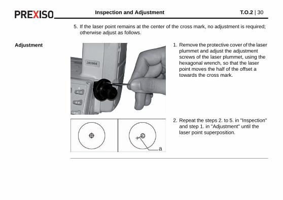
5. If the laser point remains at the center of the cross mark, no adjustment is required; otherwise adjust as follows.
Adjustment 1. Remove the protective cover of the laser plummet and adjust the adjustment screws of the laser plummet, using the hexagonal wrench, so that the laser point moves the half of the offset a towards the cross mark.
2. Repeat the steps 2. to 5. in "Inspection" and step 1. in "Adjustment" until the laser point superposition.
a
Inspection and Adjustment T.O.2 | 31
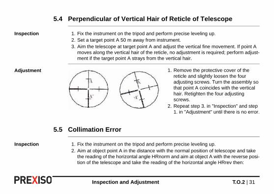
5.4 Perpendicular of Vertical Hair of Reticle of Telescope
Inspection 1. Fix the instrument on the tripod and perform precise leveling up.2. Set a target point A 50 m away from instrument.3. Aim the telescope at target point A and adjust the vertical fine movement. If point A
moves along the vertical hair of the reticle, no adjustment is required; perform adjust-ment if the target point A strays from the vertical hair.
Adjustment
5.5 Collimation Error
Inspection 1. Fix the instrument on the tripod and perform precise leveling up.2. Aim at object point A in the distance with the normal position of telescope and take
the reading of the horizontal angle HRnorm and aim at object A with the reverse posi-tion of the telescope and take the reading of the horizontal angle HRrev then:
1. Remove the protective cover of the reticle and slightly loosen the four adjusting screws. Turn the assembly so that point A coincides with the vertical hair. Retighten the four adjusting screws.
2. Repeat step 3. in "Inspection" and step 1. in "Adjustment" until there is no error.
T.O.2 | 32Inspection and Adjustment
Collimation Error C = (HRnorm - HRrev ± 180°)/2If C <10", no adjustment is required; if C >10", adjustment is required.
Adjustment 1. Adjust the horizontal fine motion in the reverse position of the telescope so that the reverse reading HRrev′ = HRrev + C.
2. Remove the protective cover of the reticle of the telescope and adjust both the left and right adjusting screws so that the vertical hair of the reticle coincides with object A.
3. Repeat the steps in "Inspection" and "Adjustment" until acceptable condition is reached.

Inspection and Adjustment T.O.2 | 33
5.6 Index Error of Vertical Circle
Inspection 1. Fix the instrument on the tripod and perform precise leveling up.2. Aim the telescope at any object point P in the normal position and take the reading of
vertical angle Vnorm.3. Turn the telescope to the reverse position and aim it at point P again. Take the reading
of other vertical angle VRev.4. If (Vnorm + VRev) - 360° = 2I, I ≤ 15", no adjustment is required; otherwise, perform
adjustment.
Adjustment 1. Press and hold R/L + HOLD buttons and press ON/OFF button. Release ON/OFF button when full character display appears and release R/L + HOLD buttons when four beeps are heard.
2. Sway the telescope near horizontal plane with instru-ment in the normal position and allow vertical angle to be reset after zero cross. Aim the telescope in the normal position at object P and press 0SET to confirm.

T.O.2 | 34Inspection and Adjustment
3. Aim the telescope in the reverse position at object P and press 0SET to confirm. With this, the compensa-tion of index error is completed.

Care and Transport T.O.2 | 35
6 Care and Transport
6.1 Transport
Transport in the field When transporting the equipment in the field, always make sure that you• either carry the product in its original transport container,• or carry the tripod with its legs splayed across your shoulder, keeping the attached
product upright.
Transport in a road vehicle
Never carry the product loose in a road vehicle, as it can be affected by shock and vibra-tion. Always carry the product in its transport container and secure it.
Shipping When transporting the product by rail, air or sea, always use the complete original PREXISO packaging, transport container and cardboard box, or its equivalent, to protect against shock and vibration.
Shipping, transport of batteries
When transporting or shipping batteries, the person in charge of the product must ensure that the applicable national and international rules and regulations are observed. Before transportation or shipping, contact your local passenger or freight transport company.
Field adjustment After transport inspect the field adjustment parameters given in this user manual before using the product.

T.O.2 | 36Care and Transport
6.2 Storage
Product Respect the temperature limits when storing the equipment, particularly in summer if the equipment is inside a vehicle. Refer to "8 Technical Data" for information about tempera-ture limits.
Field adjustment After long periods of storage inspect the field adjustment parameters given in this user manual before using the product.
Batteries • Refer to "8 Technical Data" for information about storage temperature range.• At the recommended storage temperature range, batteries containing a 10% to 50%
charge can be stored for up to one year. After this storage period the batteries must be recharged.
• Remove batteries from the product and the charger before storing.• After storage recharge batteries before using.• Protect batteries from damp and wetness. Wet or damp batteries must be dried before
storing or use.
For Ni-MH battery pack:• A storage temperature range of 0°C to +20°C/+32°F to 68°F in a dry environment is
recommended to minimise self-discharging of the battery.
For alkaline batteries:• If the equipment is to be stored for a long time, remove the alkaline batteries from the
product in order to avoid the danger of leakage.

Care and Transport T.O.2 | 37
6.3 Cleaning and Drying
Objective, eyepiece and reflectors
• Blow dust off lenses and prisms.• Never touch the glass with your fingers.• Use only a clean, soft, lint-free cloth for cleaning. If necessary, moisten the cloth with
water or pure alcohol. Do not use other liquids; these may attack the polymer compo-nents.
Charger and batteries
• Use only a clean, soft, lint-free cloth for cleaning.
Fogging of prisms Reflector prisms that are cooler than the ambient temperature tend to fog. It is not enough simply to wipe them. Keep them for some time inside your jacket or in the vehicle to allow them to adjust to the ambient temperature.
Damp products Dry the product, the transport container, the foam inserts and the accessories at a temper-ature not greater than 40°C /104°F and clean them. Do not repack until everything is completely dry. Always close the transport container when using in the field.

T.O.2 | 38Care and Transport
Cables and plugs Keep plugs clean and dry. Blow away any dirt lodged in the plugs of the connecting cables.

Safety Directions T.O.2 | 39
7 Safety Directions
7.1 General
Description The following directions enable the person responsible for the product, and the person who actually uses the equipment, to anticipate and avoid operational hazards.
The person responsible for the product must ensure that all users understand these direc-tions and adhere to them.
7.2 Intended Use
Permitted use • Measuring horizontal and vertical angles.• Visualizing the aiming direction and vertical axis.• Computing by means of software.
Adverse use • Use of the product without instruction.• Use outside of the intended limits.• Disabling safety systems.• Removal of hazard notices.• Opening the product using tools, for example screwdriver, unless this is specifically
permitted for certain functions.• Modification or conversion of the product.

T.O.2 | 40Safety Directions
• Use after misappropriation.• Use of products with obviously recognisable damages or defects.• Use with accessories from other manufacturers without the prior explicit approval of
PREXISO.• Aiming directly into the sun.• Inadequate safeguards at the working site, for example when measuring on roads.• Deliberate dazzling of third parties.• Controlling of machines, moving objects or similar monitoring application without addi-
tional control- and safety installations.
�Warning Adverse use can lead to injury, malfunction and damage.It is the task of the person responsible for the equipment to inform the user about hazards and how to counteract them. The product is not to be operated until the user has been instructed on how to work with it.
7.3 Limits of Use
Environment Suitable for use in an atmosphere appropriate for permanent human habitation: not suit-able for use in aggressive or explosive environments.
Safety Directions T.O.2 | 41
Environment charger
Suitable for use in dry environments only and not under adverse conditions.
�Danger Local safety authorities and safety experts must be contacted before working in hazardous areas, or close to electrical installations or similar situations by the person in charge of the product.
7.4 Responsibilities
Manufacturer of the product
PREXISO AG, CH-8152 Glattbrugg, hereinafter referred to as PREXISO, is responsible for supplying the product, including the user manual and original accessories, in a safe condition.
Manufacturers of non PREXISO acces-sories
The manufacturers of non PREXISO accessories for the product are responsible for developing, implementing and communicating safety concepts for their products, and are also responsible for the effectiveness of those safety concepts in combination with the PREXISO product.
Person in charge of the product
The person in charge of the product has the following duties:• To understand the safety instructions on the product and the instructions in the user
manual.• To be familiar with local regulations relating to safety and accident prevention.

T.O.2 | 42Safety Directions
• To inform PREXISO immediately if the product and the application becomes unsafe.
�Warning The person responsible for the product must ensure that it is used in accordance with the instructions. This person is also accountable for the training and the deployment of personnel who use the product and for the safety of the equipment in use.
7.5 Hazards of Use
�Warning The absence of instruction, or the inadequate imparting of instruction, can lead to incorrect or adverse use, and can cause accidents with far-reaching human, material, financial and environmental consequences.Precautions:All users must follow the safety directions given by the manufacturer and the directions of the person responsible for the product.
�Caution Watch out for erroneous measurement results if the product has been dropped or has been misused, modified, stored for long periods or transported.Precautions:Periodically carry out test measurements and perform the field adjustments indicated in the user manual, particularly after the product has been subjected to abnormal use and before and after important measurements.
Safety Directions T.O.2 | 43
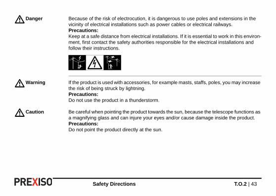
�Danger Because of the risk of electrocution, it is dangerous to use poles and extensions in the vicinity of electrical installations such as power cables or electrical railways.Precautions:Keep at a safe distance from electrical installations. If it is essential to work in this environ-ment, first contact the safety authorities responsible for the electrical installations and follow their instructions.
�Warning If the product is used with accessories, for example masts, staffs, poles, you may increase the risk of being struck by lightning.Precautions:Do not use the product in a thunderstorm.
�Caution Be careful when pointing the product towards the sun, because the telescope functions as a magnifying glass and can injure your eyes and/or cause damage inside the product.Precautions:Do not point the product directly at the sun.
T.O.2 | 44Safety Directions
�Warning During dynamic applications, for example stakeout procedures there is a danger of acci-dents occurring if the user does not pay attention to the environmental conditions around, for example obstacles, excavations or traffic.Precautions:The person responsible for the product must make all users fully aware of the existing dangers.
�Warning Inadequate securing of the working site can lead to dangerous situations, for example in traffic, on building sites, and at industrial installations.Precautions:Always ensure that the working site is adequately secured. Adhere to the regulations governing safety and accident prevention and road traffic.
�Warning If computers intended for use indoors are used in the field there is a danger of electric shock.Precautions:Adhere to the instructions given by the computer manufacturer regarding field use with PREXISO products.
�Caution If the accessories used with the product are not properly secured and the product is subjected to mechanical shock, for example blows or falling, the product may be damaged or people can sustain injury.Precautions:When setting-up the product, make sure that the accessories are correctly adapted, fitted, secured, and locked in position.Avoid subjecting the product to mechanical stress.

Safety Directions T.O.2 | 45
�Caution During the transport, shipping or disposal of batteries it is possible for inappropriate mechanical influences to constitute a fire hazard.Precautions:Before shipping the product or disposing of it, discharge the batteries by running the product until they are flat.When transporting or shipping batteries, the person in charge of the product must ensure that the applicable national and international rules and regulations are observed. Before transportation or shipping contact your local passenger or freight transport company.
�Warning Using a battery charger not recommended by PREXISO can destroy the batteries. This can cause fire or explosions.Precautions:Only use chargers recommended by PREXISO to charge the batteries.
�Warning High mechanical stress, high ambient temperatures or immersion into fluids can cause leakage, fire or explosions of the batteries.Precautions:Protect the batteries from mechanical influences and high ambient temperatures. Do not drop or immerse batteries into fluids.
�Warning If battery terminals come in contact with jewellery, keys, metallised paper or other metals, short circuited battery terminals can overheat and cause injury or fire, for example by storing or transporting in pockets.Precautions:Make sure that the battery terminals do not come into contact with metallic objects.

T.O.2 | 46Safety Directions
�Warning Batteries not recommended by PREXISO may be damaged if charged or discharged. They may burn and explode.Precautions:Only charge and discharge batteries recommended by PREXISO.
Safety Directions T.O.2 | 47
�Warning If the product is improperly disposed of, the following can happen:• If polymer parts are burnt, poisonous gases are produced which may impair health.• If batteries are damaged or are heated strongly, they can explode and cause
poisoning, burning, corrosion or environmental contamination.• By disposing of the product irresponsibly you may enable unauthorised persons to
use it in contravention of the regulations, exposing themselves and third parties to the risk of severe injury and rendering the environment liable to contamination.
Precautions:
Product specific treatment and waste management information is availablefrom PREXISO AG.
�Warning Only PREXISO authorised service workshops are entitled to repair these products.
For the charger:
�Danger The product is not designed for use under wet and severe conditions. If unit becomes wet it may cause you to receive an electric shock.Precautions:Use the product only in dry environments, for example in buildings or vehicles. Protect the product against humidity. If the product becomes humid, it must not be used!
The product must not be disposed with household waste.Dispose of the product appropriately in accordance with the national regula-tions in force in your country.Always prevent access to the product by unauthorised personnel.

T.O.2 | 48Safety Directions
�Warning If you open the product, either of the following actions may cause you to receive an electric shock.• Touching live components• Using the product after incorrect attempts were made to carry out repairs.Precautions:Do not open the product. Only PREXISO authorised service workshops are entitled to repair these products.
7.6 Laser Classification
7.6.1 General
General The following directions (in accordance with the state of the art - international standard IEC 60825-1 (2007-03) and IEC TR 60825-14 (2004-02)) provide instruction and training infor-mation to the person responsible for the product and the person who actually uses the equipment, to anticipate and avoid operational hazards.
The person responsible for the product must ensure that all users understand these direc-tions and adhere to them.
Safety Directions T.O.2 | 49
7.6.2 Laser Plummet
General The laser plummet built into the product produces a visible red laser beam which emerges from the bottom of the product.
The laser product described in this section, is classified as laser class 2 in accordance with:• IEC 60825-1 (2007-03): "Safety of laser products".• EN 60825-1 (2007-10): "Safety of laser products".
Class 2 laser products:These products are safe for momentary exposures but can be hazardous for deliberate staring into the beam.
Products classified as laser class 1, class 2 and class 3R do not require:• laser safety officer involvement,• protective clothes and eyewear,• special warning signs in the laser working area
if used and operated as defined in this user manual due to the low eye hazard level.
Products classified as laser class 2 or class 3R may cause dazzle, flash-blindness and afterimages, particularly under low ambient light conditions.
T.O.2 | 50Safety Directions
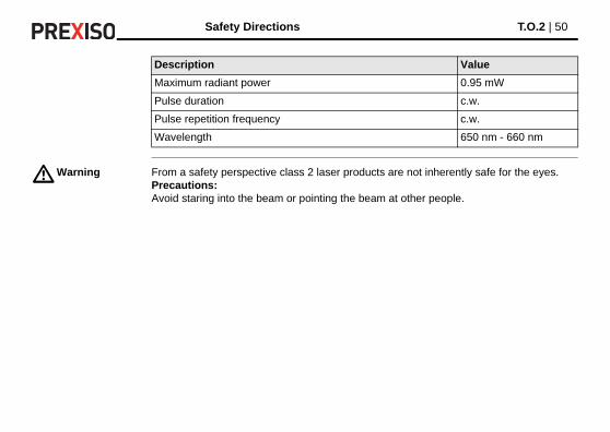
�Warning From a safety perspective class 2 laser products are not inherently safe for the eyes.Precautions:Avoid staring into the beam or pointing the beam at other people.
Description Value
Maximum radiant power 0.95 mW
Pulse duration c.w.
Pulse repetition frequency c.w.
Wavelength 650 nm - 660 nm
Safety Directions T.O.2 | 51
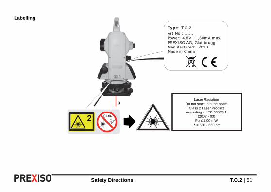
Labelling
Type: T.O.2 Art.No.: ......Power: 4.8V ,60mA max.PREXISO AG, GlattbruggManufactured: 2010Made in China
aLaser Radiation
Do not stare into the beamClass 2 Laser Product
according to IEC 60825-1(2007 - 03)
Po ≤ 1.00 mW λ = 650 - 660 nm

T.O.2 | 52Safety Directions
7.7 Electromagnetic Compatibility EMC
Description The term Electromagnetic Compatibility is taken to mean the capability of the product to function smoothly in an environment where electromagnetic radiation and electrostatic discharges are present, and without causing electromagnetic disturbances to other equip-ment.
1 Exit for laser beam2 Laser beam

Safety Directions T.O.2 | 53
Warning Electromagnetic radiation can cause disturbances in other equipment.
Although the product meets the strict regulations and standards which are in force in this respect, PREXISO cannot completely exclude the possibility that other equipment may be disturbed.
Caution There is a risk that disturbances may be caused in other equipment if the product is used with accessories from other manufacturers, for example field computers, personal computers, two-way radios, non-standard cables or external batteries.Precautions:Use only the equipment and accessories recommended by PREXISO. When combined with the product, they meet the strict requirements stipulated by the guidelines and stand-ards. When using computers and two-way radios, pay attention to the information about electromagnetic compatibility provided by the manufacturer.
Caution Disturbances caused by electromagnetic radiation can result in erroneous measurements.Although the product meets the strict regulations and standards which are in force in this respect, PREXISO cannot completely exclude the possibility that the product may be disturbed by intense electromagnetic radiation, for example, near radio transmitters, two-way radios or diesel generators.Precautions:Check the plausibility of results obtained under these conditions.
Warning If the product is operated with connecting cables attached at only one of their two ends, for example external supply cables, interface cables, the permitted level of electromag-
T.O.2 | 54Safety Directions
netic radiation may be exceeded and the correct functioning of other products may be impaired.Precautions:While the product is in use, connecting cables, for example product to external battery, product to computer, must be connected at both ends.

Technical Data T.O.2 | 55
8 Technical Data
Telescope
Angle Measuring System
Compensator
Image: ErectMagnification ratio: 30xEffective aperture of object lense: 45 mmAngle of view: 1°30’Shortest visibility distance: 1.35 mStadia multiplication constant: 100Stadia addition constant: 0Resolution: 3"
Mode of angle measurement: Photoelectric incremental readingMinimum reading: 1", 5"Detection method: H: Dual side
V: Single sidePrecision of angle measurement: 2"Unit of angle: DEG, MIL, GONDisplay: LCD double side
Tilt sensor: Automatic vertical compensationRange of compensation: ±3'
T.O.2 | 56Technical Data
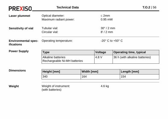
Laser plummet
Sensitivity of vial
Environmental spec-ifications
Power Supply
Dimensions
Weight
Optical diameter: 2mmMaximum radiant power: 0.95 mW
Tubular vial: 30" / 2 mmCircular vial: 8' / 2 mm
Operating temperature: -20° C to +50° C
Type Voltage Operating time, typical
Alkaline batteriesRechargeable Ni-MH batteries
4.8 V 36 h (with alkaline batteries)
Height [mm] Width [mm] Length [mm]
340 164 154
Weight of instrument:(with batteries)
4.6 kg

International Limited Warranty T.O.2 | 57
9 International Limited Warranty
International Limited Warranty
This product is subject to the terms and conditions set out in the International Limited Warranty which you can download from the PREXISO home page at http://www.prexiso.com or collect from your PREXISO distributor.
The foregoing warranty is exclusive and is in lieu of all other warranties, terms or condi-tions, express or implied, either in fact or by operation of law, statutory or otherwise, including warranties, terms or conditions of merchantability, fitness for a particular purpose, satisfactory quality and non-infringement, all of which are expressly disclaimed.

T.O.2 | 58Accessories
10 Accessories
List of accessories • 1 set of plumb bob• 1 tool kit (containing a screw driver and 2 needles)• 2 bags of desiccant• 1 rain cover• 1 instruction manual• 1 charger• AA-battery case• 1 Ni-MH battery pack
Error Information T.O.2 | 59
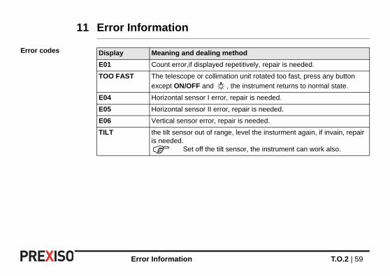
11 Error Information
Error codes Display Meaning and dealing method
E01 Count error,if displayed repetitively, repair is needed.
TOO FAST The telescope or collimation unit rotated too fast, press any button
except ON/OFF and , the instrument returns to normal state.
E04 Horizontal sensor I error, repair is needed.
E05 Horizontal sensor II error, repair is needed.
E06 Vertical sensor error, repair is needed.
TILT the tilt sensor out of range, level the insturment again, if invain, repair is needed.
Set off the tilt sensor, the instrument can work also.

PREXISO T.O.2
785191-1.0.0en, Original text© 2010 PREXISO AG, Glattbrugg, Switzerland
PREXISO AGwww.prexiso.com