preventing undesirable seismic behaviour of infill walls in design...
TRANSCRIPT
Construcţii Preventing Undesirable Seismic Behaviour of Infill Walls •A. Noorifard, F. M. Saradj, M. R. Tabeshpour
57
PREVENTING UNDESIRABLE SEISMIC BEHAVIOUR OFINFILL WALLS IN DESIGN PROCESS
Azadeh NOORIFARDPh.D. Candidate, Architect, Department of Architecture and Environmental
Design, Iran University of Science and Technology, Tehran, Iran,e-mail: [email protected]
Fatemeh Mehdizadeh SARADJAssociate Professor, PhD, Department of Architecture and Environmental
Design, Iran University of Science and Technology, Tehran, Iran,e-mail: [email protected]
Mohammad Reza TABESHPOURAssistant Professor, PhD, Department of Mechanical Engineering, Sharif
University of Technology, Tehran, Iran,e-mail: [email protected]
Abstract. Dividing walls are usually considered as non-structural elements,but experiences of past earthquakes show that some buildings designedand constructed by engineers have been damaged during earthquakesbecause of disregarding the negative effects of walls. Apart from the poorquality of construction and materials, inattention in design process is themain reason for undesirable seismic behaviour of walls.The main aim ofthis paper is to investigate the measures taken in different stages ofarchitectural and structural design for improving the seismic behaviour ofinfilled concrete structures. As a general principle, with the furtherprogress of project from basic architectural design to detailed structuraldesign, there is a need to reduce designer authority and increase obligation,furthermore the cost of project increases too. The conclusion of this studyimplies that, in order to achieve the desirable seismic behaviour of walls,close collaboration between architects and structural engineers is requiredfrom the early stages of design. The results of this study are presented in acheck list for designing reinforced concrete (RC) moment resisting frameand RC shear wall.
Key words: Walls, Seismic Behaviour, Architectural Design, StructuralDesign, Concrete Structures
1. IntroductionExperiences of past earthquakes showmost of non-structural elements such asarchitectural elements are damaged evenin mild or moderate earthquakes (Lee etal., 2007; Tasligedik et al., 2011; Vicente etal., 2012). Walls are one of the mostimportant architectural elements that have
been damaged in past earthquakes andcan lead to the collapse of buildings.Evaluation of walls’ behaviour shows thatapart from the poor quality ofconstruction and materials, inattention tothe design process is the main cause ofdamage to walls and their adverse effectson the seismic performance of structures.
• Urbanism. Arhitectură. Construcţii • Vol. 8 • Nr. 1 • 2017
58
In the current design process, structuralengineers usually consider masonry infillwalls as non-structural elements and onlycalculate their weight during structuralanalysis and design (Mostafaei andKabeyasawa, 2004; Kaushik et al., 2006;Mondal and Jain, 2008; Tsai and Huang,2009; Rodrigues et al., 2010; Pradhan et al.,2012; Noorifard et al., 2014; Noorifard etal., 2015; Bârnaure et al., 2016). Theyassume that architects are responsible fordesigning walls and they themselves donot need to do anything. On the otherhand, architects determine thespecifications of walls and theirarrangement in plan and elevationwithout considering their seismicbehaviour (Noorifard et al., 2016). Theyassume that structural engineers areresponsible for designing buildingsagainst seismic forces. While designing ina seismic area is a shared architectural andengineering responsibility (Saradj, 2008).In this way, one of the most importantnon-structural elements with the potentialto destroy the whole building has beenneglected in the engineering community(Noorifard et al., 2016). However, theexperiences of past earthquakes show that,despite the special attention to the seismicresistant design of structures, disregardingthe design of infill walls can causeirreparable damage to lives and property.Even beyond this, many scholars andpracticing architects think that it issufficient that structural engineerscalculate the structure after architecturaldesign is completed (Bachmann, 2003;Erman, 2005). Even the cleverestcalculations and detailed design cannotcompensate for errors and defects in theconceptual seismic design of the structureor in the selection of non-structuralelements, in particular partition walls andfacade elements (Bachmann, 2003). In factEarthquake-resistant design includes twoinseparable parts, namely earthquake-resistant structural design and
earthquake-resistant architectural design,both of them are equally important in theentire design process (Erman, 2005). Forreducing vulnerability and costs, closecollaboration between the architect andthe engineer from the earliest planningstage to construction stage is essential(Bachmann, 2003; Saradj, 2008).
Basically, the range of seismic behaviourof walls is wide. In the past earthquakes,numerous buildings designed byengineers were severely damaged or evencollapsed as a result of anomalies in thebasic structural system induced by non-structural masonry partitions. Althoughthere were other buildings without anylateral force resistance elementsconstructed by non-specialist peopleremained stable as a result of thecontribution of masonry infill walls. Inthis paper, only effective measures toprotect undesirable seismic behaviour ofwalls are investigated, in other words,using the potential of walls for the lateralresistance of buildings which is a higherlevel of seismic performance will not beconsidered.
Accordingly, the main research questionsare formed as follows:
1. How are walls damaged duringearthquakes?
2. How can walls cause damage tostructure during earthquakes?
3. Are the effects of walls on seismi cperformance of different types ofcommon structural systems thesame?
4. Which measures can preventundesirable seismic behaviour of wallsat different stages of architectural andstructural design?
5. Who is responsible for the poor seismicperformance of walls in conventionalmedium rise buildings (structuralengineers or architects)?
Construcţii Preventing Undesirable Seismic Behaviour of Infill Walls •A. Noorifard, F. M. Saradj, M. R. Tabeshpour
59
To answer these questions, four mainstages are defined for this study. First, theconventional process of architectural andstructural design and measures taken byarchitects and structural engineers indifferent stages of basic and detail designare investigated. Then, the undesirableseismic behaviour of walls (either theirown damage or causing damage to themain structure) is discussed on threegeneral levels based on the experiences ofpast earthquakes. On each level, the main
causes of damage are presented accordingto the documents of past earthquakes.Moreover for each case, an attempt will bemade to present the provision of seismiccodes briefly and conceptually.
Infill walls have the most influences onthe seismic behaviour of reinforcedconcrete moment frames and more thanhalf of current buildings in developingcountries are constructed by reinforcedconcrete.
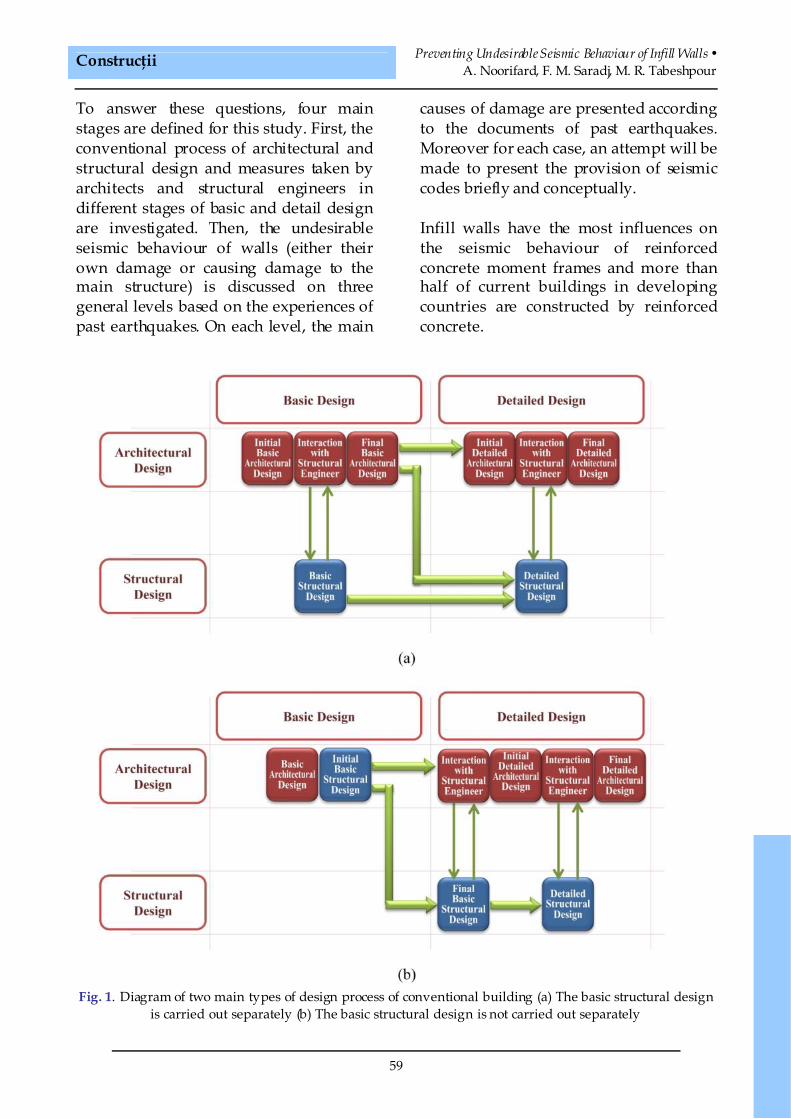
Fig. 1. Diagram of two main types of design process of conventional building (a) The basic structural designis carried out separately (b) The basic structural design is not carried out separately
• Urbanism. Arhitectură. Construcţii • Vol. 8 • Nr. 1 • 2017
60
This study selected these two types ofstructures consisting of 1- Reinforcedconcrete moment resisting frame and 2-Reinforced concrete frame with shearwalls. So, in the next section, the stiffnessof these systems is compared with infillwalls and the importance of each of theabove damages and the effect of walls onthe seismic performance of each system isdetermined. Finally the results of studiesin the above three sections are presentedin a check lists for designers. This checklist will be arranged in the form of amatrix. The rows of the matrix are relatedto the undesirable seismic behaviour ofwalls and the columns are related to thedifferent stages of basic and detailedarchitectural and structural design. Ineach element of matrix, effectivemeasures are presented to preventundesirable seismic behaviour of walls.
2. Design process in conventionalbuilding
In this section, a brief review of decisionswhich are made in the different stages ofarchitectural and structural design andhave influence on seismic performance ofwall are presented. Fig. 1 focuses on twomain types of design process inconventional buildings.
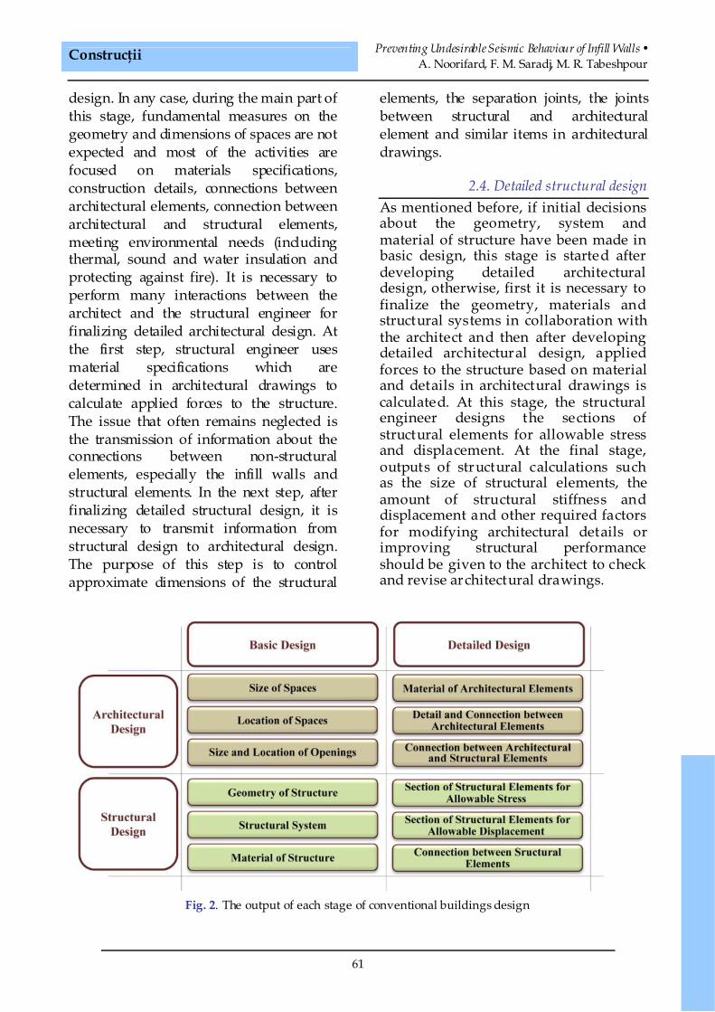
2.1. Basic architectural designThe main decisions which have beenmade by architects at this stage includeconsidering the context and the site ofproject, climate and how to use naturallight and ventilation, determining thequality of spaces, spatial relationships,functional relationships, form, volumetriccomposition, size of spaces, circulationand access routes. In fact, at the end ofthis stage, the size and location of spacesand openings are almost final. Accordingto Fig. 1 if the basic structural design iscarried out separately, at final stages ofbasic architectural design, an interaction
between the architect and the structuralengineer is needed to finalize geometry,system and material of the structure. Ifthe basic structural design is not carriedout separately, architects make initialdecisions in this regard at the final stagesof basic architectural design and it isfinalized by structural engineer inprimary stages of detailed structuraldesign.
2.2. Basic structural designIn this stage, decisions such as selectingstructural system (moment resisting frame,shear wall, braced frame and dual system),material of structure (reinforced concrete,steel), determining geometry of structure(location of columns, shear walls andbraced frames) are made. As mentioned inbasic architectural design, these decisionsmay be made separately by structuralengineers, in basic structural design, or apart of them are made by architects in basicarchitectural design and the others bystructural engineers in early stages ofdetailed structural design. In any case, inthis stage interaction between the architectand the structural engineer is necessary tomake decisions about geometry, systemand material of structure.
2.3. Detailed architectural designAt this stage, if interaction between thearchitect and the structural engineer hasbeen performed in the final stage of basicarchitectural design and necessarymodifications have been applied, alleffective cases on geometry of spaces isfinalized and the only factor that does nothave a high degree of certainty is detail andsection of structural elements, the amountof stiffness and displacement of structure.As mentioned in the previous paragraph,required interaction between the architectand the structural engineer may beperformed in the early stage of detaileddesign instead of the final stage of basic
Construcţii Preventing Undesirable Seismic Behaviour of Infill Walls •A. Noorifard, F. M. Saradj, M. R. Tabeshpour
61
design. In any case, during the main part ofthis stage, fundamental measures on thegeometry and dimensions of spaces are notexpected and most of the activities arefocused on materials specifications,construction details, connections betweenarchitectural elements, connection betweenarchitectural and structural elements,meeting environmental needs (includingthermal, sound and water insulation andprotecting against fire). It is necessary toperform many interactions between thearchitect and the structural engineer forfinalizing detailed architectural design. Atthe first step, structural engineer usesmaterial specifications which aredetermined in architectural drawings tocalculate applied forces to the structure.The issue that often remains neglected isthe transmission of information about theconnections between non-structuralelements, especially the infill walls andstructural elements. In the next step, afterfinalizing detailed structural design, it isnecessary to transmit information fromstructural design to architectural design.The purpose of this step is to controlapproximate dimensions of the structural
elements, the separation joints, the jointsbetween structural and architecturalelement and similar items in architecturaldrawings.
2.4. Detailed structural designAs mentioned before, if initial decisionsabout the geometry, system andmaterial of structure have been made inbasic design, this stage is started afterdeveloping detailed architecturaldesign, otherwise, first it is necessary tofinalize the geometry, materials andstructural systems in collaboration withthe architect and then after developingdetailed architectural design, appliedforces to the structure based on materialand details in architectural drawings iscalculated. At this stage, the structuralengineer designs the sections ofstructural elements for allowable stressand displacement. At the final stage,outputs of structural calculations suchas the size of structural elements, theamount of structural stiffness anddisplacement and other required factorsfor modifying architectural details orimproving structural performanceshould be given to the architect to checkand revise architectural drawings.
Fig. 2. The output of each stage of conventional buildings design
• Urbanism. Arhitectură. Construcţii • Vol. 8 • Nr. 1 • 2017
62
According to the description presentedin this section, the main issues whichare used in the next section against theundesirable seismic behaviour of wallsare presented in Fig. 2.
3. Undesirable seismic behaviour ofwalls
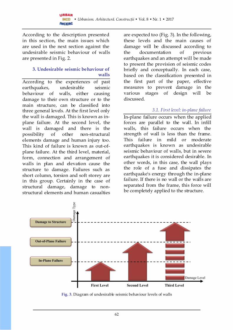
According to the experiences of pastearthquakes, undesirable seismicbehaviour of walls, either causingdamage to their own structure or to themain structure, can be classified intothree general levels. At the first level onlythe wall is damaged. This is known as in-plane failure. At the second level, thewall is damaged and there is thepossibility of other non-structuralelements damage and human injury too.This kind of failure is known as out-of-plane failure. At the third level, material,form, connection and arrangement ofwalls in plan and elevation cause thestructure to damage. Failures such asshort column, torsion and soft storey arein this group. Certainly in the case ofstructural damage, damage to non-structural elements and human casualties
are expected too (Fig. 3). In the following,these levels and the main causes ofdamage will be discussed according tothe documentation of previousearthquakes and an attempt will be madeto present the provision of seismic codesbriefly and conceptually. In each case,based on the classification presented inthe first part of the paper, effectivemeasures to prevent damage in thevarious stages of design will bediscussed.
3.1. First level: in-plane failureIn-plane failure occurs when the appliedforces are parallel to the wall. In infillwalls, this failure occurs when thestrength of wall is less than the frame.This failure in mild or moderateearthquakes is known as undesirableseismic behaviour of walls, but in severeearthquakes it is considered desirable. Inother words, in this case, the wall playsthe role of a fuse and dissipates theearthquake's energy through the in-planefailure. If there is no wall or the walls areseparated from the frame, this force willbe completely applied to the structure.
Fig. 3. Diagram of undesirable seismic behaviour levels of walls
Construcţii Preventing Undesirable Seismic Behaviour of Infill Walls •A. Noorifard, F. M. Saradj, M. R. Tabeshpour
63
Weak components and joints, andlocation and size of openings can benoted as two categories of factors of thislevel of failure.
3.1.1. In-plane failure induced by weakcomponents and joints
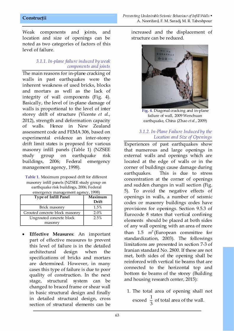
The main reasons for in-plane cracking ofwalls in past earthquakes were theinherent weakness of used bricks, blocksand mortars as well as the lack ofintegrity of wall components (Fig. 4).Basically, the level of in-plane damage ofwalls is proportional to the level of interstorey drift of structure (Vicente et al.,2012), strength and deformation capacityof walls. Hence in New Zealandassessment code and FEMA 306, based onexperimental evidence an inter-storeydrift limit states is proposed for variousmasonry infill panels (Table 1) (NZSEEstudy group on earthquake riskbuildings, 2006; Federal emergencymanagement agency, 1998).
Table 1. Maximum proposed drift for differentmasonry infill panels (NZSEE study group on
earthquake risk buildings, 2006; Federalemergency management agency, 1998)Type of Infill Panel Maximum
DriftBrick masonry 1.5%
Grouted concrete block masonry 2.0%Ungrouted concrete block
masonry2.5%
· Effective Measures: An importantpart of effective measures to preventthis level of failure is in the detailedarchitectural design when thespecifications of bricks and mortarsare determined. However, in manycases this type of failure is due to poorquality of construction. In the nextstage, structural system can bechanged to braced frame or shear wallin basic structural design and finallyin detailed structural design, crosssection of structural elements can be
increased and the displacement ofstructure can be reduced.
Fig. 4. Diagonal cracking and in-planefailure of wall, 2009 Wenchuan
earthquake, China (Zhao et al., 2009)
3.1.2. In-Plane Failure Induced by theLocation and Size of Openings
Experiences of past earthquakes showthat numerous and large openings inexternal walls and openings which arelocated at the edge of walls or in thecorner of buildings cause damage duringearthquakes. This is due to stressconcentration at the corner of openingsand sudden changes in wall section (Fig.5). To avoid the negative effects ofopenings in walls, a number of seismiccodes or masonry buildings codes haveprovisions for openings. Section 9.5.3 ofEurocode 8 states that vertical confiningelements should be placed at both sidesof any wall opening with an area of morethan 1.5 2m (European committee forstandardization, 2003). The followingslimitations are presented in section 7-3 ofIranian standard No. 2800. If these are notmet, both sides of the opening shall bereinforced with vertical tie beams that areconnected to the horizontal top andbottom tie beams of the storey (Buildingand housing research center, 2015):
1. The total area of opening shall not
exceed 13
of total area of the wall.
• Urbanism. Arhitectură. Construcţii • Vol. 8 • Nr. 1 • 2017
64
2. The total length of the openings shall
not exceed 12
of the length of the wall.
3. The distance of the first opening fromthe external edge of the building shall
be less than 23
of the height of the
opening or 75 cm, whichever is less.4. The horizontal distance between two
adjacent openings shall not be less
than 23
of the height of the shorter of
the two openings and also less than16
of the sum of the lengths of the
two openings.5. Neither of the dimensions of the
opening shall exceed 2.5 meters.
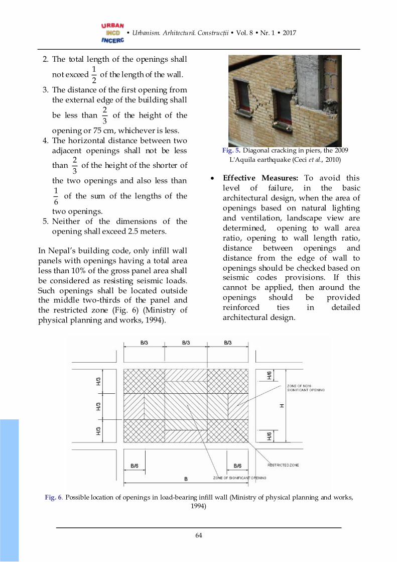
In Nepal’s building code, only infill wallpanels with openings having a total arealess than 10% of the gross panel area shallbe considered as resisting seismic loads.Such openings shall be located outsidethe middle two-thirds of the panel andthe restricted zone (Fig. 6) (Ministry ofphysical planning and works, 1994).
Fig. 5. Diagonal cracking in piers, the 2009L'Aquila earthquake (Ceci et al., 2010)
· Effective Measures: To avoid thislevel of failure, in the basicarchitectural design, when the area ofopenings based on natural lightingand ventilation, landscape view aredetermined, opening to wall arearatio, opening to wall length ratio,distance between openings anddistance from the edge of wall toopenings should be checked based onseismic codes provisions. If thiscannot be applied, then around theopenings should be providedreinforced ties in detailedarchitectural design.
Fig. 6. Possible location of openings in load-bearing infill wall (Ministry of physical planning and works,1994)
Construcţii Preventing Undesirable Seismic Behaviour of Infill Walls •A. Noorifard, F. M. Saradj, M. R. Tabeshpour
65
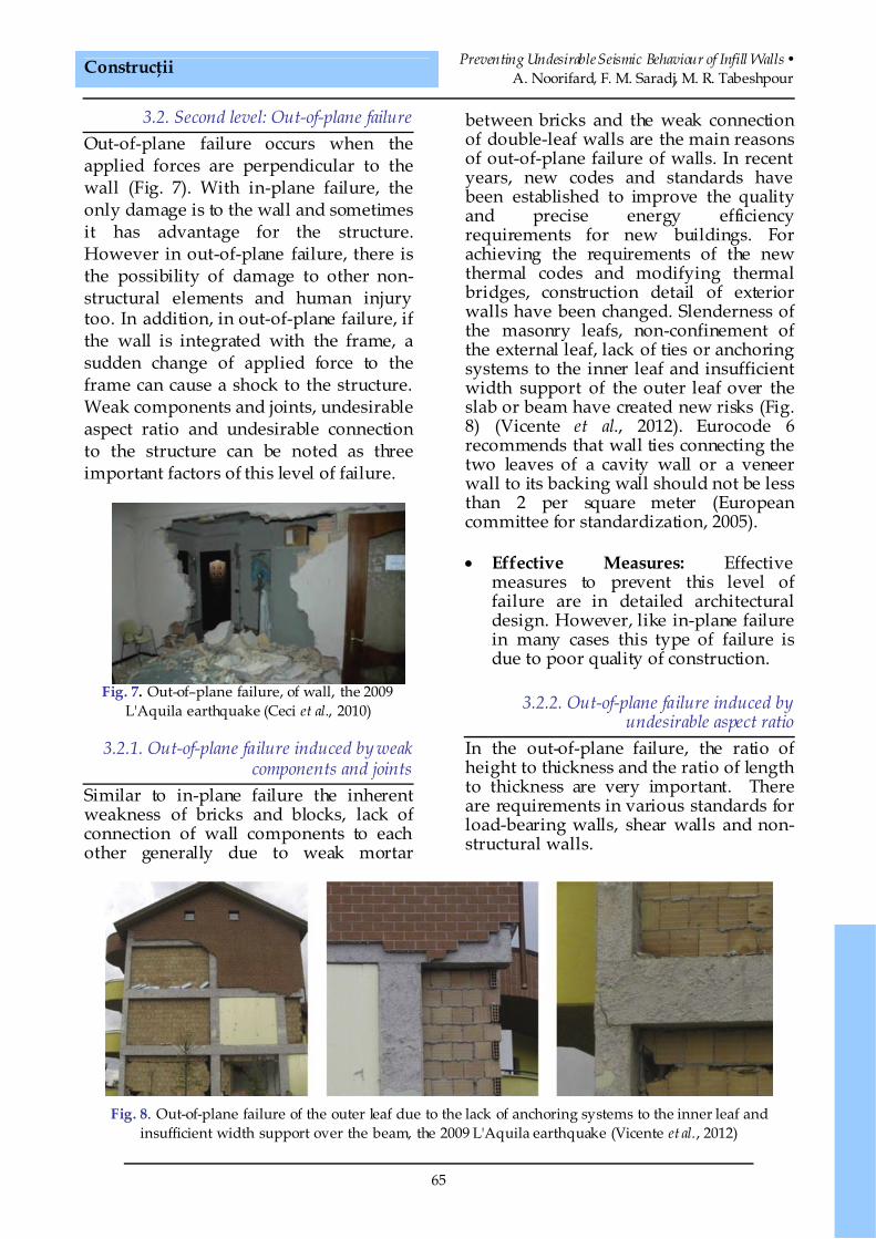
3.2. Second level: Out-of-plane failureOut-of-plane failure occurs when theapplied forces are perpendicular to thewall (Fig. 7). With in-plane failure, theonly damage is to the wall and sometimesit has advantage for the structure.However in out-of-plane failure, there isthe possibility of damage to other non-structural elements and human injurytoo. In addition, in out-of-plane failure, ifthe wall is integrated with the frame, asudden change of applied force to theframe can cause a shock to the structure.Weak components and joints, undesirableaspect ratio and undesirable connectionto the structure can be noted as threeimportant factors of this level of failure.
Fig. 7. Out-of–plane failure, of wall, the 2009L'Aquila earthquake (Ceci et al., 2010)
3.2.1. Out-of-plane failure induced by weakcomponents and joints
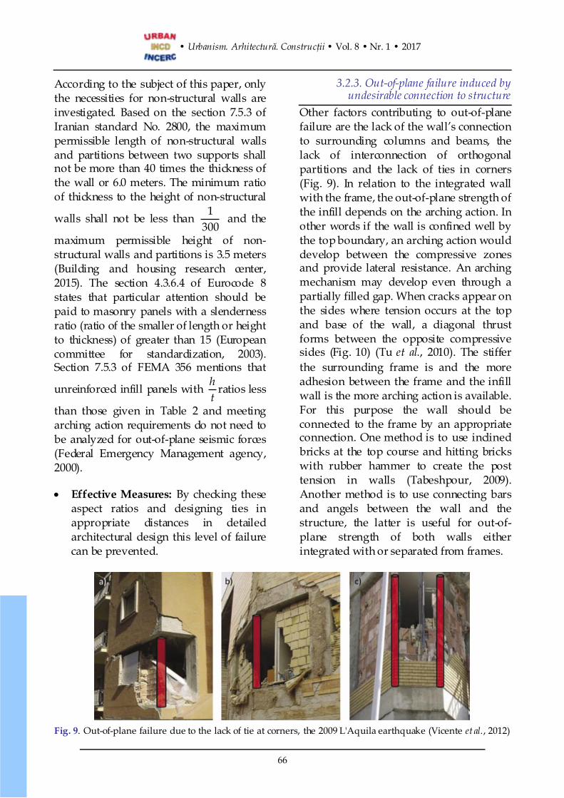
Similar to in-plane failure the inherentweakness of bricks and blocks, lack ofconnection of wall components to eachother generally due to weak mortar
between bricks and the weak connectionof double-leaf walls are the main reasonsof out-of-plane failure of walls. In recentyears, new codes and standards havebeen established to improve the qualityand precise energy efficiencyrequirements for new buildings. Forachieving the requirements of the newthermal codes and modifying thermalbridges, construction detail of exteriorwalls have been changed. Slenderness ofthe masonry leafs, non-confinement ofthe external leaf, lack of ties or anchoringsystems to the inner leaf and insufficientwidth support of the outer leaf over theslab or beam have created new risks (Fig.8) (Vicente et al., 2012). Eurocode 6recommends that wall ties connecting thetwo leaves of a cavity wall or a veneerwall to its backing wall should not be lessthan 2 per square meter (Europeancommittee for standardization, 2005).
· Effective Measures: Effectivemeasures to prevent this level offailure are in detailed architecturaldesign. However, like in-plane failurein many cases this type of failure isdue to poor quality of construction.
3.2.2. Out-of-plane failure induced byundesirable aspect ratio
In the out-of-plane failure, the ratio ofheight to thickness and the ratio of lengthto thickness are very important. Thereare requirements in various standards forload-bearing walls, shear walls and non-structural walls.
Fig. 8. Out-of-plane failure of the outer leaf due to the lack of anchoring systems to the inner leaf andinsufficient width support over the beam, the 2009 L'Aquila earthquake (Vicente et al., 2012)
• Urbanism. Arhitectură. Construcţii • Vol. 8 • Nr. 1 • 2017
66
According to the subject of this paper, onlythe necessities for non-structural walls areinvestigated. Based on the section 7.5.3 ofIranian standard No. 2800, the maximumpermissible length of non-structural wallsand partitions between two supports shallnot be more than 40 times the thickness ofthe wall or 6.0 meters. The minimum ratioof thickness to the height of non-structural
walls shall not be less than 1300
and the
maximum permissible height of non-structural walls and partitions is 3.5 meters(Building and housing research center,2015). The section 4.3.6.4 of Eurocode 8states that particular attention should bepaid to masonry panels with a slendernessratio (ratio of the smaller of length or heightto thickness) of greater than 15 (Europeancommittee for standardization, 2003).Section 7.5.3 of FEMA 356 mentions that
unreinforced infill panels with ht
ratios less
than those given in Table 2 and meetingarching action requirements do not need tobe analyzed for out-of-plane seismic forces(Federal Emergency Management agency,2000).
· Effective Measures: By checking theseaspect ratios and designing ties inappropriate distances in detailedarchitectural design this level of failurecan be prevented.
3.2.3. Out-of-plane failure induced byundesirable connection to structure
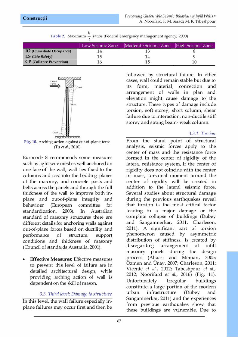
Other factors contributing to out-of-planefailure are the lack of the wall’s connectionto surrounding columns and beams, thelack of interconnection of orthogonalpartitions and the lack of ties in corners(Fig. 9). In relation to the integrated wallwith the frame, the out-of-plane strength ofthe infill depends on the arching action. Inother words if the wall is confined well bythe top boundary, an arching action woulddevelop between the compressive zonesand provide lateral resistance. An archingmechanism may develop even through apartially filled gap. When cracks appear onthe sides where tension occurs at the topand base of the wall, a diagonal thrustforms between the opposite compressivesides (Fig. 10) (Tu et al., 2010). The stifferthe surrounding frame is and the moreadhesion between the frame and the infillwall is the more arching action is available.For this purpose the wall should beconnected to the frame by an appropriateconnection. One method is to use inclinedbricks at the top course and hitting brickswith rubber hammer to create the posttension in walls (Tabeshpour, 2009).Another method is to use connecting barsand angels between the wall and thestructure, the latter is useful for out-of-plane strength of both walls eitherintegrated with or separated from frames.
Fig. 9. Out-of-plane failure due to the lack of tie at corners, the 2009 L'Aquila earthquake (Vicente et al., 2012)
Construcţii Preventing Undesirable Seismic Behaviour of Infill Walls •A. Noorifard, F. M. Saradj, M. R. Tabeshpour
67
Table 2. Maximumht
ratios (Federal emergency management agency, 2000)
Low Seismic Zone Moderate Seismic Zone High Seismic ZoneIO (Immediate Occupancy) 14 13 8LS (Life Safety) 15 14 9CP (Collapse Prevention) 16 15 10
Fig. 10. Arching action against out-of-plane force(Tu et al., 2010)
Eurocode 8 recommends some measuressuch as light wire meshes well anchored onone face of the wall, wall ties fixed to thecolumns and cast into the bedding planesof the masonry, and concrete posts andbelts across the panels and through the fullthickness of the wall to improve both in-plane and out-of-plane integrity andbehaviour (European committee forstandardization, 2003). In Australianstandard of masonry structures there aredifferent details for anchoring walls againstout-of-plane forces based on ductility andperformance of structure, supportconditions and thickness of masonry(Council of standards Australia, 2001).
· Effective Measures: Effective measuresto prevent this level of failure are indetailed architectural design, whileproviding arching action of wall isdependent on the skill of mason.
3.3. Third level: Damage to structureIn this level, the wall failure especially in-plane failures may occur first and then be
followed by structural failure. In othercases, wall could remain stable but due toits form, material, connection andarrangement of walls in plan andelevation might cause damage to thestructure. These types of damage includetorsion, soft storey, short column, shearfailure due to interaction, non-ductile stiffstorey and strong beam- weak column.
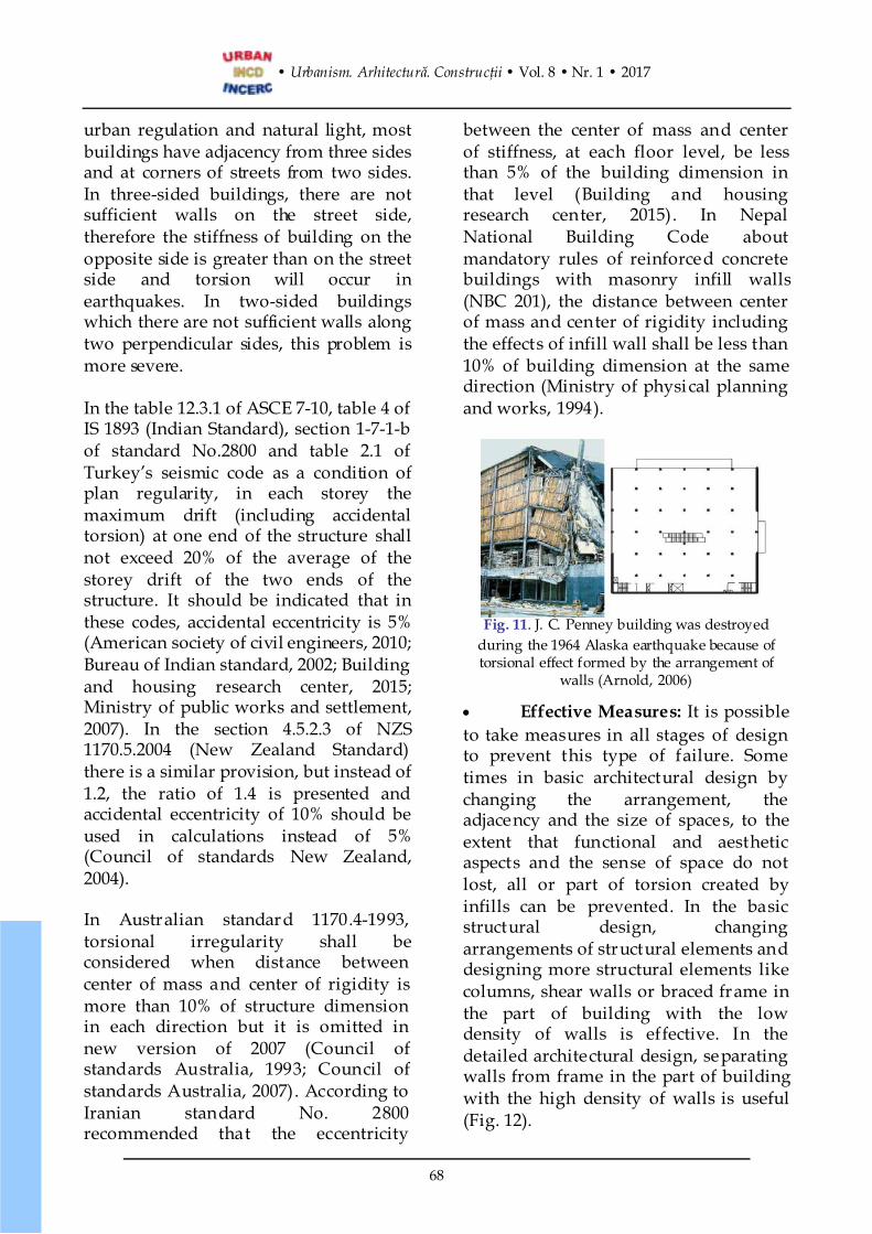
3.3.1. TorsionFrom the stand point of structuralanalysis, seismic forces apply to thecenter of mass and the resistance forceformed in the center of rigidity of thelateral resistance system, if the center ofrigidity does not coincide with the centerof mass, torsional moment around thecenter of rigidity will be created inaddition to the lateral seismic force.Several studies about structural damageduring the previous earthquakes revealthat torsion is the most critical factorleading to a major damage or thecomplete collapse of buildings (Dubeyand Sangamnerkar, 2011; Charleson,2011). A significant part of torsionphenomenon caused by asymmetricdistribution of stiffness, is created bydisregarding arrangement of infillmasonry panels during the designprocess (Aliaari and Memari, 2005;Özmen and Ünay, 2007; Charleson, 2011;Vicente et al., 2012; Tabeshpour et al.,2012; Noorifard et al., 2016) (Fig. 11).Unfortunately Irregular buildingsconstitute a large portion of the modernurban infrastructure (Dubey andSangamnerkar, 2011) and the experiencesfrom previous earthquakes show thatthese buildings are vulnerable. Due to
• Urbanism. Arhitectură. Construcţii • Vol. 8 • Nr. 1 • 2017
68
urban regulation and natural light, mostbuildings have adjacency from three sidesand at corners of streets from two sides.In three-sided buildings, there are notsufficient walls on the street side,therefore the stiffness of building on theopposite side is greater than on the streetside and torsion will occur inearthquakes. In two-sided buildingswhich there are not sufficient walls alongtwo perpendicular sides, this problem ismore severe.
In the table 12.3.1 of ASCE 7-10, table 4 ofIS 1893 (Indian Standard), section 1-7-1-bof standard No.2800 and table 2.1 ofTurkey’s seismic code as a condition ofplan regularity, in each storey themaximum drift (including accidentaltorsion) at one end of the structure shallnot exceed 20% of the average of thestorey drift of the two ends of thestructure. It should be indicated that inthese codes, accidental eccentricity is 5%(American society of civil engineers, 2010;Bureau of Indian standard, 2002; Buildingand housing research center, 2015;Ministry of public works and settlement,2007). In the section 4.5.2.3 of NZS1170.5.2004 (New Zealand Standard)there is a similar provision, but instead of1.2, the ratio of 1.4 is presented andaccidental eccentricity of 10% should beused in calculations instead of 5%(Council of standards New Zealand,2004).
In Australian standard 1170.4-1993,torsional irregularity shall beconsidered when distance betweencenter of mass and center of rigidity ismore than 10% of structure dimensionin each direction but it is omitted innew version of 2007 (Council ofstandards Australia, 1993; Council ofstandards Australia, 2007). According toIranian standard No. 2800recommended that the eccentricity
between the center of mass and centerof stiffness, at each floor level, be lessthan 5% of the building dimension inthat level (Building and housingresearch center, 2015). In NepalNational Building Code aboutmandatory rules of reinforced concretebuildings with masonry infill walls(NBC 201), the distance between centerof mass and center of rigidity includingthe effects of infill wall shall be less than10% of building dimension at the samedirection (Ministry of physical planningand works, 1994).
Fig. 11. J. C. Penney building was destroyedduring the 1964 Alaska earthquake because oftorsional effect formed by the arrangement of
walls (Arnold, 2006)
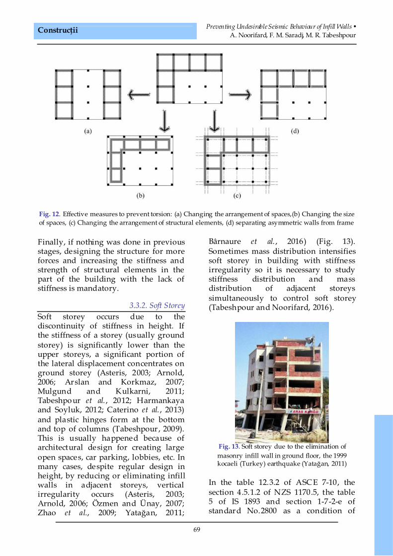
· Effective Measures: It is possibleto take measures in all stages of designto prevent this type of failure. Sometimes in basic architectural design bychanging the arrangement, theadjacency and the size of spaces, to theextent that functional and aestheticaspects and the sense of space do notlost, all or part of torsion created byinfills can be prevented. In the basicstructural design, changingarrangements of structural elements anddesigning more structural elements likecolumns, shear walls or braced frame inthe part of building with the lowdensity of walls is effective. In thedetailed architectural design, separatingwalls from frame in the part of buildingwith the high density of walls is useful(Fig. 12).
Construcţii Preventing Undesirable Seismic Behaviour of Infill Walls •A. Noorifard, F. M. Saradj, M. R. Tabeshpour
69
Fig. 12. Effective measures to prevent torsion: (a) Changing the arrangement of spaces,(b) Changing the sizeof spaces, (c) Changing the arrangement of structural elements, (d) separating asymmetric walls from frame
Finally, if nothing was done in previousstages, designing the structure for moreforces and increasing the stiffness andstrength of structural elements in thepart of the building with the lack ofstiffness is mandatory.
3.3.2. Soft StoreySoft storey occurs due to thediscontinuity of stiffness in height. Ifthe stiffness of a storey (usually groundstorey) is significantly lower than theupper storeys, a significant portion ofthe lateral displacement concentrates onground storey (Asteris, 2003; Arnold,2006; Arslan and Korkmaz, 2007;Mulgund and Kulkarni, 2011;Tabeshpour et al. , 2012; Harmankayaand Soyluk, 2012; Caterino et al. , 2013)and plastic hinges form at the bottomand top of columns (Tabeshpour, 2009).This is usually happened because ofarchitectural design for creating largeopen spaces, car parking, lobbies, etc. Inmany cases, despite regular design inheight, by reducing or eliminating infillwalls in adjacent storeys, verticalirregularity occurs (Asteris, 2003;Arnold, 2006; Özmen and Ünay, 2007;Zhao et al., 2009; Yatağan, 2011;
Bârnaure et al. , 2016) (Fig. 13).Sometimes mass distribution intensifiessoft storey in building with stiffnessirregularity so it is necessary to studystiffness distribution and massdistribution of adjacent storeyssimultaneously to control soft storey(Tabeshpour and Noorifard, 2016).
Fig. 13. Soft storey due to the elimination ofmasonry infill wall in ground floor, the 1999kocaeli (Turkey) earthquake (Yatağan, 2011)
In the table 12.3.2 of ASCE 7-10, thesection 4.5.1.2 of NZS 1170.5, the table5 of IS 1893 and section 1-7-2-e ofstandard No.2800 as a condition of
• Urbanism. Arhitectură. Construcţii • Vol. 8 • Nr. 1 • 2017
70
vertical regularity, the lateral sti ffnessof each storey shall not be less than70% of that in the storey above or 80%of the average stiffness of the threestoreys above (American society o f civilengineers 7-10, 2010; Council ofstandards New Zealand, 2004; Bureau
of Indian standard, 2002; Building andhousing research center, 2015). There isthe same provision in Australianstandard 1170.4-1993, but it is omittedin new version of 2007 (Council ofstandards Australia, 1993; Council ofstandards Australia, 2007).
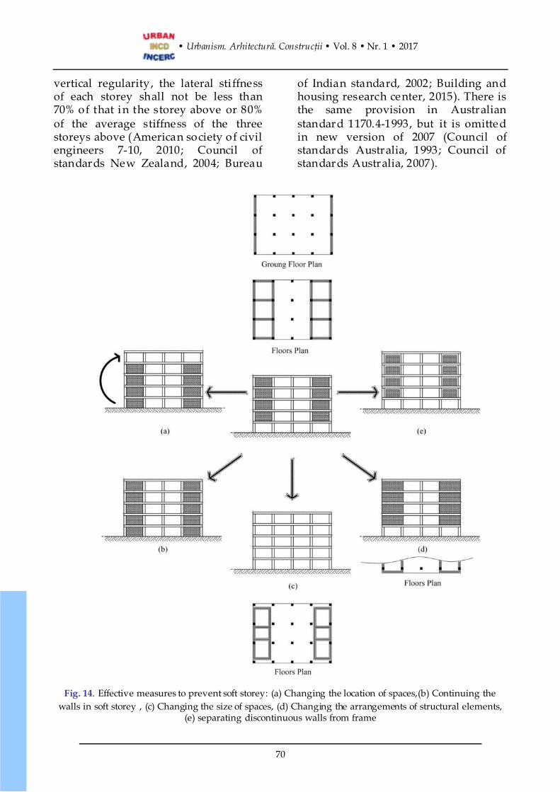
Fig. 14. Effective measures to prevent soft storey: (a) Changing the location of spaces,(b) Continuing thewalls in soft storey , (c) Changing the size of spaces, (d) Changing the arrangements of structural elements,
(e) separating discontinuous walls from frame
Construcţii Preventing Undesirable Seismic Behaviour of Infill Walls •A. Noorifard, F. M. Saradj, M. R. Tabeshpour
71
In Table 2.1 of seismic code of Turkey as acondition of inter storey stiffnessirregularity (soft storey) has beenindicated that Stiffness Irregularity Factorwhich is defined as the ratio of theaverage relative storey drift at any storeyto the average relative storey drift at thestorey immediately above or below, isgreater than 2 in each of the twoorthogonal directions, ±%5 additionaleccentricities shall be considered incalculation (Ministry of public works andsettlement, 2007).
· Effective Measures: It is possible totake measures in all stages of designto prevent this type of failure liketorsion. Some times in the basicarchitectural design by changing thelocation and size of spaces, to theextent that functional and aestheticaspects and sense of space do notlost, all or part of soft storey createdby infills can be prevented. In thebasic structural design, changingarrangements of structural elementsand designing more structuralelements like columns, shear wallsor braced frame in the storey wherethe infill walls are less than others iseffective. In detailed architecturaldesign, separating walls which arenot continuous in elevation fromframe is useful (Fig. 14). Finally, ifnothing is done in previous stages,designing the structural elements insoft storey for more forces andincreasing stiffness and strength ofstructural elements in this storey, ismandatory.
3.3.3. Short columnShort columns are usually created by lowpartition walls, which are not isolatedfrom the structure (Aliaari and Memari,2005; Vicente et al., 2012; Urich andBeauperthuy, 2012). The stiffness of the
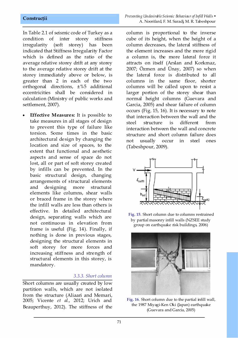
column is proportional to the inversecube of its height, when the height of acolumn decreases, the lateral stiffness ofthe element increases and the more rigida column is, the more lateral force itattracts on itself (Arslan and Korkmaz,2007; Özmen and Ünay, 2007) so whenthe lateral force is distributed to allcolumns in the same floor, shortercolumns will be called upon to resist alarger portion of the storey shear thannormal height columns (Guevara andGarcia, 2005) and shear failure of columnoccurs (Fig. 15, 16). It is necessary to notethat interaction between the wall and thesteel structure is different frominteraction between the wall and concretestructure and short column failure doesnot usually occur in steel ones(Tabeshpour, 2009).
Fig. 15. Short column due to columns restrainedby partial masonry infill walls (NZSEE study
group on earthquake risk buildings, 2006)
Fig. 16. Short column due to the partial infill wall,the 1987 Miyagi-Ken Oki (Japan) earthquake
(Guevara and Garcia, 2005)
• Urbanism. Arhitectură. Construcţii • Vol. 8 • Nr. 1 • 2017
72
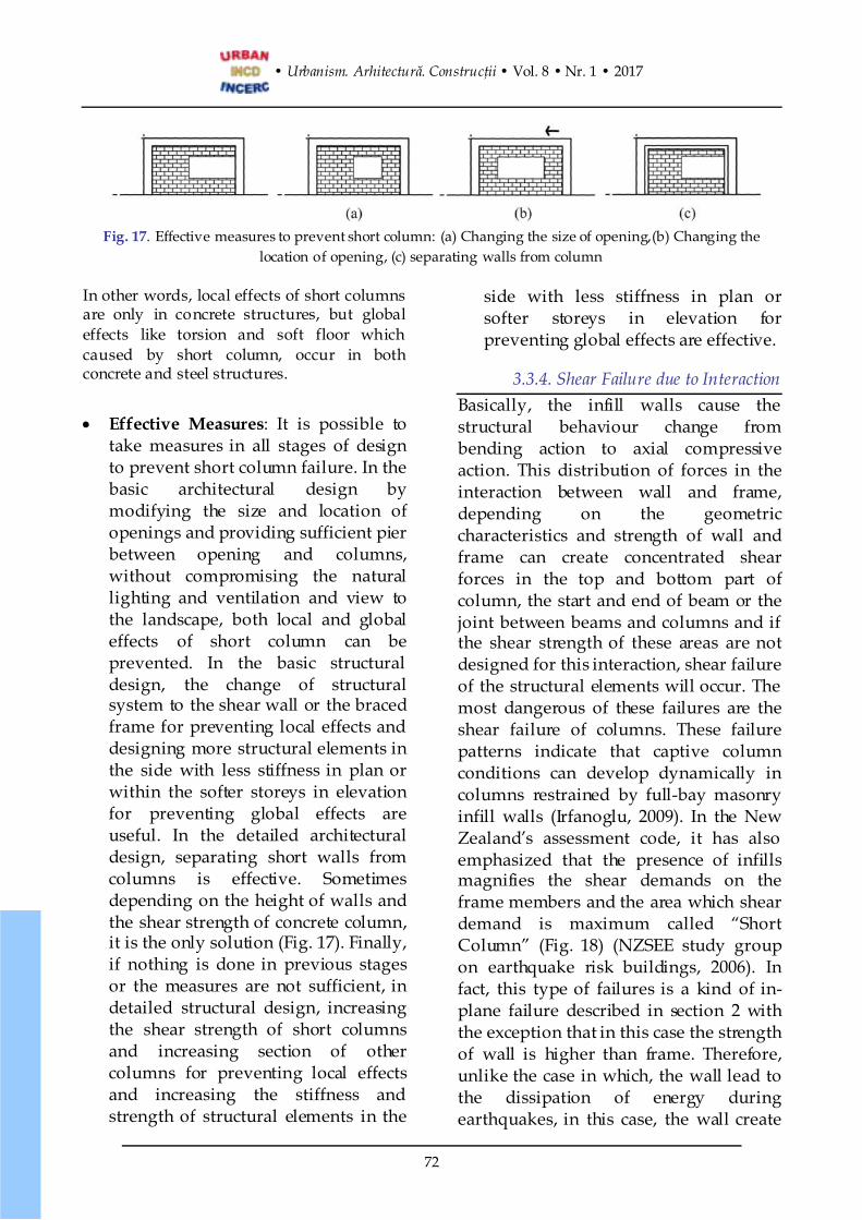
Fig. 17. Effective measures to prevent short column: (a) Changing the size of opening,(b) Changing thelocation of opening, (c) separating walls from column
In other words, local effects of short columnsare only in concrete structures, but globaleffects like torsion and soft floor whichcaused by short column, occur in bothconcrete and steel structures.
· Effective Measures: It is possible totake measures in all stages of designto prevent short column failure. In thebasic architectural design bymodifying the size and location ofopenings and providing sufficient pierbetween opening and columns,without compromising the naturallighting and ventilation and view tothe landscape, both local and globaleffects of short column can beprevented. In the basic structuraldesign, the change of structuralsystem to the shear wall or the bracedframe for preventing local effects anddesigning more structural elements inthe side with less stiffness in plan orwithin the softer storeys in elevationfor preventing global effects areuseful. In the detailed architecturaldesign, separating short walls fromcolumns is effective. Sometimesdepending on the height of walls andthe shear strength of concrete column,it is the only solution (Fig. 17). Finally,if nothing is done in previous stagesor the measures are not sufficient, indetailed structural design, increasingthe shear strength of short columnsand increasing section of othercolumns for preventing local effectsand increasing the stiffness andstrength of structural elements in the
side with less stiffness in plan orsofter storeys in elevation forpreventing global effects are effective.
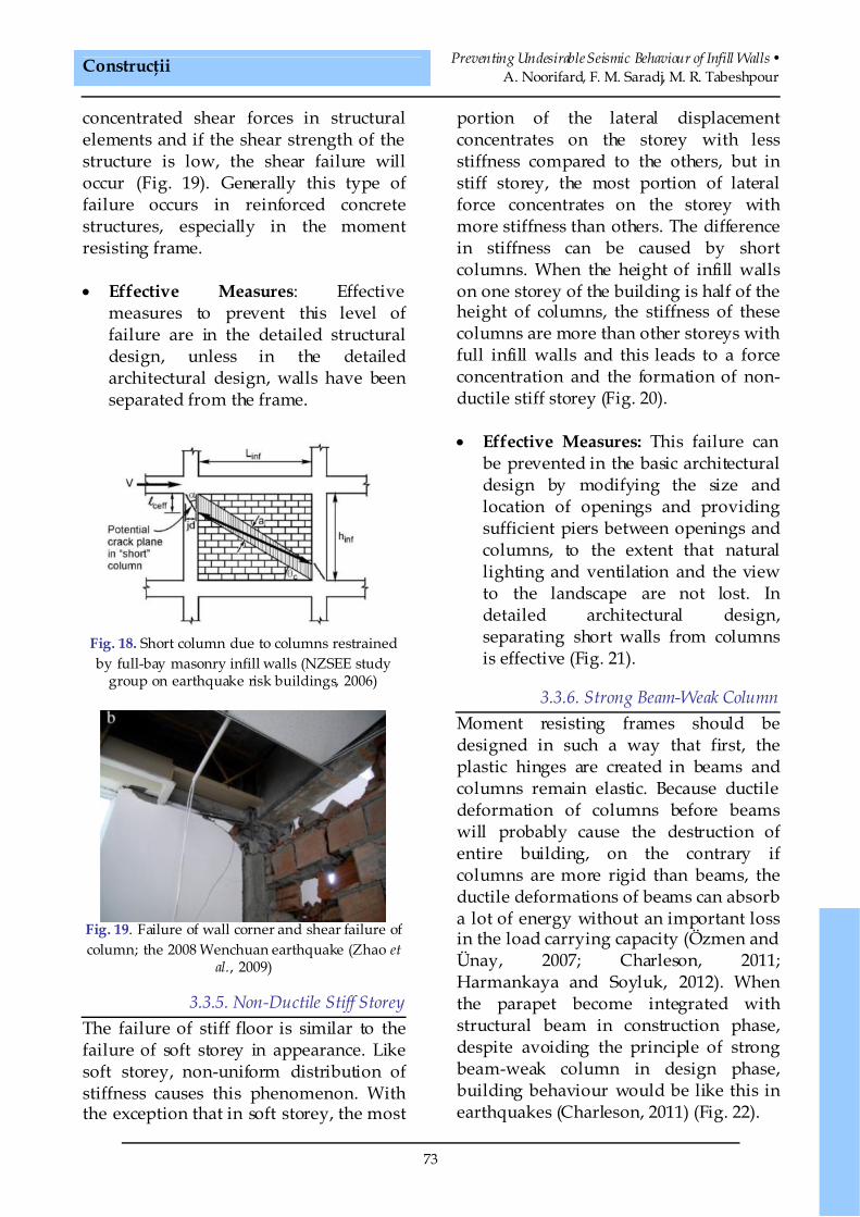
3.3.4. Shear Failure due to InteractionBasically, the infill walls cause thestructural behaviour change frombending action to axial compressiveaction. This distribution of forces in theinteraction between wall and frame,depending on the geometriccharacteristics and strength of wall andframe can create concentrated shearforces in the top and bottom part ofcolumn, the start and end of beam or thejoint between beams and columns and ifthe shear strength of these areas are notdesigned for this interaction, shear failureof the structural elements will occur. Themost dangerous of these failures are theshear failure of columns. These failurepatterns indicate that captive columnconditions can develop dynamically incolumns restrained by full-bay masonryinfill walls (Irfanoglu, 2009). In the NewZealand’s assessment code, it has alsoemphasized that the presence of infillsmagnifies the shear demands on theframe members and the area which sheardemand is maximum called “ShortColumn” (Fig. 18) (NZSEE study groupon earthquake risk buildings, 2006). Infact, this type of failures is a kind of in-plane failure described in section 2 withthe exception that in this case the strengthof wall is higher than frame. Therefore,unlike the case in which, the wall lead tothe dissipation of energy duringearthquakes, in this case, the wall create
Construcţii Preventing Undesirable Seismic Behaviour of Infill Walls •A. Noorifard, F. M. Saradj, M. R. Tabeshpour
73
concentrated shear forces in structuralelements and if the shear strength of thestructure is low, the shear failure willoccur (Fig. 19). Generally this type offailure occurs in reinforced concretestructures, especially in the momentresisting frame.
· Effective Measures: Effectivemeasures to prevent this level offailure are in the detailed structuraldesign, unless in the detailedarchitectural design, walls have beenseparated from the frame.
Fig. 18. Short column due to columns restrainedby full-bay masonry infill walls (NZSEE study
group on earthquake risk buildings, 2006)
Fig. 19. Failure of wall corner and shear failure ofcolumn; the 2008 Wenchuan earthquake (Zhao et
al., 2009)
3.3.5. Non-Ductile Stiff StoreyThe failure of stiff floor is similar to thefailure of soft storey in appearance. Likesoft storey, non-uniform distribution ofstiffness causes this phenomenon. Withthe exception that in soft storey, the most
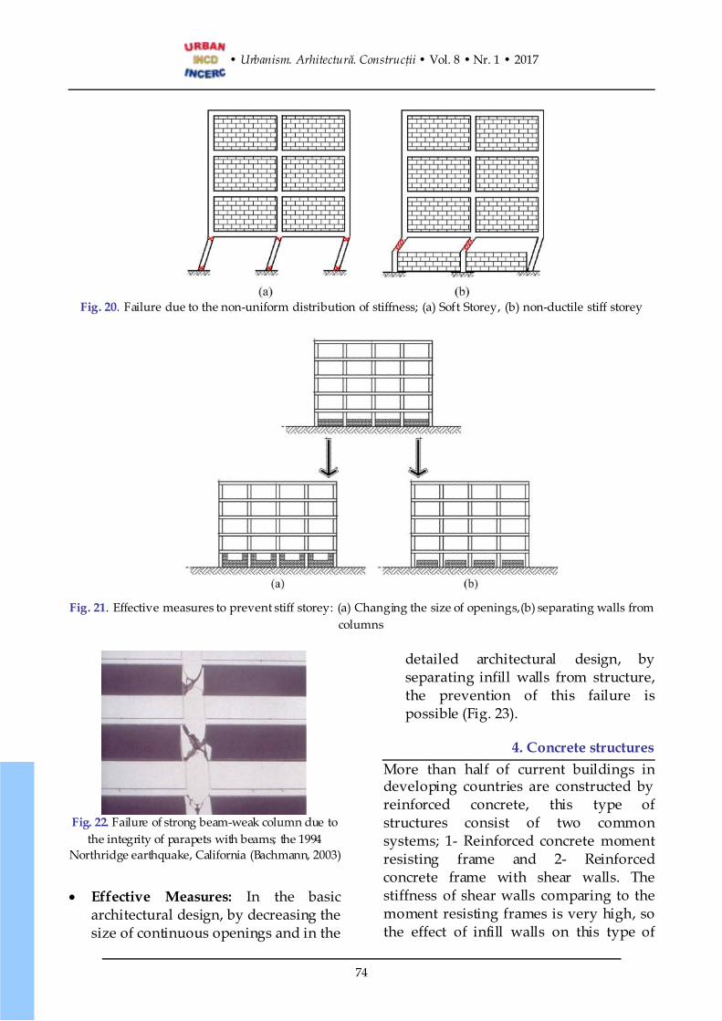
portion of the lateral displacementconcentrates on the storey with lessstiffness compared to the others, but instiff storey, the most portion of lateralforce concentrates on the storey withmore stiffness than others. The differencein stiffness can be caused by shortcolumns. When the height of infill wallson one storey of the building is half of theheight of columns, the stiffness of thesecolumns are more than other storeys withfull infill walls and this leads to a forceconcentration and the formation of non-ductile stiff storey (Fig. 20).
· Effective Measures: This failure canbe prevented in the basic architecturaldesign by modifying the size andlocation of openings and providingsufficient piers between openings andcolumns, to the extent that naturallighting and ventilation and the viewto the landscape are not lost. Indetailed architectural design,separating short walls from columnsis effective (Fig. 21).
3.3.6. Strong Beam-Weak ColumnMoment resisting frames should bedesigned in such a way that first, theplastic hinges are created in beams andcolumns remain elastic. Because ductiledeformation of columns before beamswill probably cause the destruction ofentire building, on the contrary ifcolumns are more rigid than beams, theductile deformations of beams can absorba lot of energy without an important lossin the load carrying capacity (Özmen andÜnay, 2007; Charleson, 2011;Harmankaya and Soyluk, 2012). Whenthe parapet become integrated withstructural beam in construction phase,despite avoiding the principle of strongbeam-weak column in design phase,building behaviour would be like this inearthquakes (Charleson, 2011) (Fig. 22).
• Urbanism. Arhitectură. Construcţii • Vol. 8 • Nr. 1 • 2017
74
Fig. 20. Failure due to the non-uniform distribution of stiffness; (a) Soft Storey, (b) non-ductile stiff storey
Fig. 21. Effective measures to prevent stiff storey: (a) Changing the size of openings,(b) separating walls fromcolumns
Fig. 22. Failure of strong beam-weak column due tothe integrity of parapets with beams; the 1994
Northridge earthquake, California (Bachmann, 2003)
· Effective Measures: In the basicarchitectural design, by decreasing thesize of continuous openings and in the
detailed architectural design, byseparating infill walls from structure,the prevention of this failure ispossible (Fig. 23).
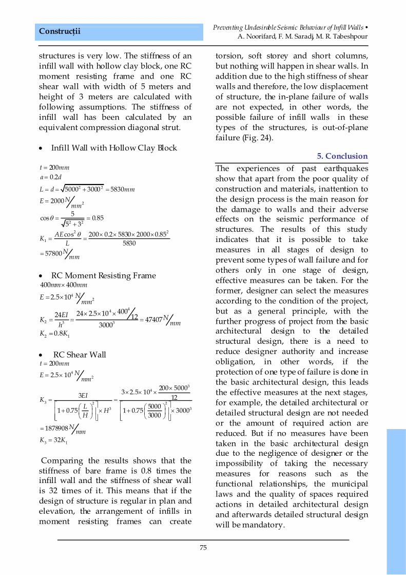
4. Concrete structuresMore than half of current buildings indeveloping countries are constructed byreinforced concrete, this type ofstructures consist of two commonsystems; 1- Reinforced concrete momentresisting frame and 2- Reinforcedconcrete frame with shear walls. Thestiffness of shear walls comparing to themoment resisting frames is very high, sothe effect of infill walls on this type of
Construcţii Preventing Undesirable Seismic Behaviour of Infill Walls •A. Noorifard, F. M. Saradj, M. R. Tabeshpour
75
structures is very low. The stiffness of aninfill wall with hollow clay block, one RCmoment resisting frame and one RCshear wall with width of 5 meters andheight of 3 meters are calculated withfollowing assumptions. The stiffness ofinfill wall has been calculated by anequivalent compression diagonal strut.
· Infill Wall with Hollow Clay Block
2 2
2
2 2
2 2
1
2000.2
5000 3000 5830
2000
5cos 0.855 3cos 200 0.2 5830 2000 0.85
583057800
t mma d
L d mmNE
mm
AEKL
Nmm
q
q
==
= = + =
=
= =+
´ ´ ´ ´= =
=
· RC Moment Resisting Frame
42
44
2 3 3
2 1
400 400
2.5 10
40024 2.5 1024 12 474073000
0.8
mm mmNE
mm
EI NK mmhK K
´
= ´
´ ´ ´= = =
=
· RC Shear Wall
42
34
3 2 23 3
3 1
200
2.5 10
200 50003 2.5 103 1250001 0.75 1 0.75 30003000
1878908
32
t mmNE mm
EIKL HH
Nmm
K K
=
= ´
´´ ´ ´
= =é ù é ùæ ö æ ö+ ´ + ´ê ú ê úç ÷ ç ÷
è ø è øê ú ê úë û ë û
=
=
Comparing the results shows that thestiffness of bare frame is 0.8 times theinfill wall and the stiffness of shear wallis 32 times of it. This means that if thedesign of structure is regular in plan andelevation, the arrangement of infills inmoment resisting frames can create
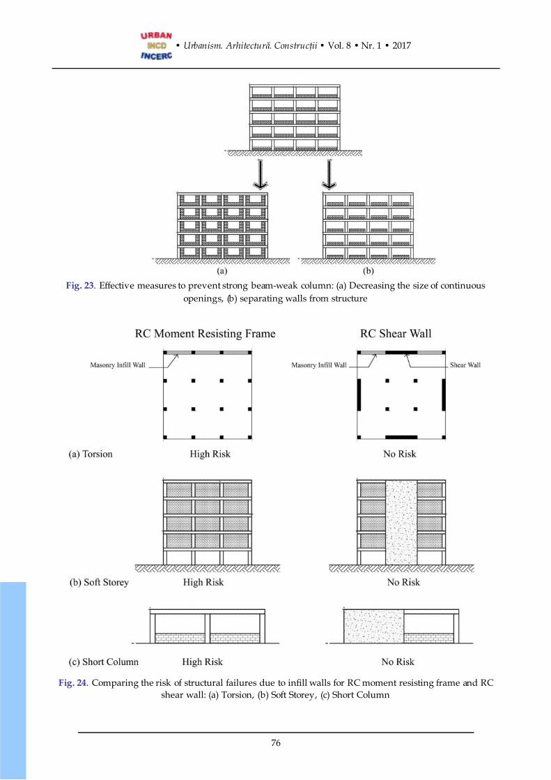
torsion, soft storey and short columns,but nothing will happen in shear walls. Inaddition due to the high stiffness of shearwalls and therefore, the low displacementof structure, the in-plane failure of wallsare not expected, in other words, thepossible failure of infill walls in thesetypes of the structures, is out-of-planefailure (Fig. 24).
5. ConclusionThe experiences of past earthquakesshow that apart from the poor quality ofconstruction and materials, inattention tothe design process is the main reason forthe damage to walls and their adverseeffects on the seismic performance ofstructures. The results of this studyindicates that it is possible to takemeasures in all stages of design toprevent some types of wall failure and forothers only in one stage of design,effective measures can be taken. For theformer, designer can select the measuresaccording to the condition of the project,but as a general principle, with thefurther progress of project from the basicarchitectural design to the detailedstructural design, there is a need toreduce designer authority and increaseobligation, in other words, if theprotection of one type of failure is done inthe basic architectural design, this leadsthe effective measures at the next stages,for example, the detailed architectural ordetailed structural design are not neededor the amount of required action arereduced. But if no measures have beentaken in the basic architectural designdue to the negligence of designer or theimpossibility of taking the necessarymeasures for reasons such as thefunctional relationships, the municipallaws and the quality of spaces requiredactions in detailed architectural designand afterwards detailed structural designwill be mandatory.
• Urbanism. Arhitectură. Construcţii • Vol. 8 • Nr. 1 • 2017
76
Fig. 23. Effective measures to prevent strong beam-weak column: (a) Decreasing the size of continuousopenings, (b) separating walls from structure
Fig. 24. Comparing the risk of structural failures due to infill walls for RC moment resisting frame and RCshear wall: (a) Torsion, (b) Soft Storey, (c) Short Column
Construcţii Preventing Undesirable Seismic Behaviour of Infill Walls •A. Noorifard, F. M. Saradj, M. R. Tabeshpour
77
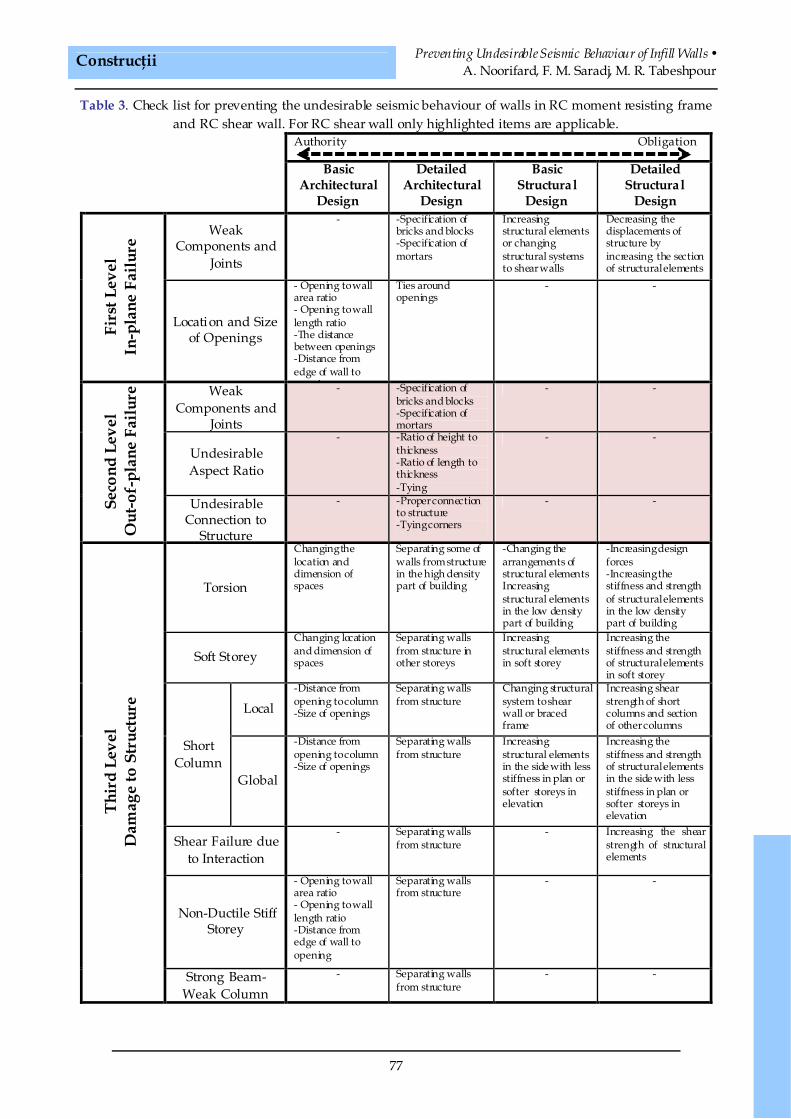
Table 3. Check list for preventing the undesirable seismic behaviour of walls in RC moment resisting frameand RC shear wall. For RC shear wall only highlighted items are applicable.
Authority Obligation
BasicArchitectural
Design
DetailedArchitectural
Design
BasicStructural
Design
DetailedStructural
Design
WeakComponents and
Joints
- -Specification ofbricks and blocks-Specification ofmortars
Increasingstructural elementsor changingstructural systemsto shear walls
Decreasing thedisplacements ofstructure byincreasing the sectionof structural elements
Firs
tLev
elIn
-pla
neFa
ilure
Location and Sizeof Openings
- Opening to wallarea ratio- Opening to walllength ratio-The distancebetween openings-Distance fromedge of wall toopening
Ties aroundopenings
- -
WeakComponents and
Joints
- -Specification ofbricks and blocks-Specification ofmortars
- -
UndesirableAspect Ratio
- -Ratio of height tothickness-Ratio of length tothickness-Tying
- -
Seco
ndLe
vel
Out
-of-
plan
eFa
ilure
UndesirableConnection to
Structure
- -Proper connectionto structure-Tying corners
- -
Torsion
Changing thelocation anddimension ofspaces
Separating some ofwalls from structurein the high densitypart of building
-Changing thearrangements ofstructural elementsIncreasingstructural elementsin the low densitypart of building
-Increasing designforces-Increasing thestiffness and strengthof structural elementsin the low densitypart of building
Soft StoreyChanging locationand dimension ofspaces
Separating wallsfrom structure inother storeys
Increasingstructural elementsin soft storey
Increasing thestiffness and strengthof structural elementsin soft storey
Local-Distance fromopening to column-Size of openings
Separating wallsfrom structure
Changing structuralsystem to shearwall or bracedframe
Increasing shearstrength of shortcolumns and sectionof other columns
ShortColumn
Global
-Distance fromopening to column-Size of openings
Separating wallsfrom structure
Increasingstructural elementsin the side with lessstiffness in plan orsofter storeys inelevation
Increasing thestiffness and strengthof structural elementsin the side with lessstiffness in plan orsofter storeys inelevation
Shear Failure dueto Interaction
- Separating wallsfrom structure
- Increasing the shearstrength of structuralelements
Non-Ductile StiffStorey
- Opening to wallarea ratio- Opening to walllength ratio-Distance fromedge of wall toopening
Separating wallsfrom structure
- -
Thir
dLe
vel
Dam
age
toSt
ruct
ure
Strong Beam-Weak Column
- Separating wallsfrom structure
- -
• Urbanism. Arhitectură. Construcţii • Vol. 8 • Nr. 1 • 2017
78
It is obvious that from the basicarchitectural design to the detailedstructural design, the cost of projectincreases too. For example, if modifyingthe location and size of spaces is possibleto protect building against torsion causedby the arrangement of infill walls, extracosts will not be imposed to the structure,however if this is resolved in the detailedstructural design, increasing the stiffnessand strength of structural elements in theparts of building with the lack ofstiffness, will be mandatory. So comparedto the first case, the cost of the structurewill be increased. It should be mentionedthat in some cases, the effective measuresin the detailed architectural design arepreferred to the basic structural designand in some cases, it is reversed.Obviously, the failure for which there isonly a preventive measure, this ismandatory. Despite the fact that at firstglance walls are non-structural elements,this study implies that to preventundesirable seismic behaviour of walls,special measures are needed both inarchitectural and structural design. Inother words, to achieve the desirableseismic behaviour of walls and to preventany interference in the seismicperformance of structures, closecollaboration between architects andstructural engineers is required from theearly stages of basic design to the finalstages of detail design. The results of thisstudy are presented in a check list fordesigners to prevent undesirable seismicbehaviour of walls in RC momentresisting frame and RC shear wall. Thischeck list is arranged in the form of amatrix of 12×4. The rows of this matrixare related to the undesirable seismicbehaviour of walls and the columns arerelated to the different stages of basic anddetailed architectural and structuraldesign. In each element of matrix,effective measures which can be taken to
prevent undesirable seismic behaviour ofwalls are presented. It should be notedthat for shear wall only highlighted itemsare applicable (Table 3).
REFERENCES
Aliaari M., Memari A. M. (2005), Analysis ofmasonry infilled steel frames with seismicisolator subframes, Engineering Structures27(4): 487–500.
American Society of Civil Engineers (2010), ASCE7-10: Minimum design loads for buildingsand other structures, American Society ofCivil Engineers, Reston, Virginia, UnitedStates.
Arnold C. (2006), Seismic issues in architecturaldesign, in: Earthquake engineeringresearch institute, FEMA 454: Designingfor earthquakes, A manual for architects,FEMA, Washington DC, United States,pp. 5-1-5-53.
Arslan M. H., Korkmaz H. H. (2007), What is to belearned from damage and failure of reinforcedconcrete structures during recent earthquakesin Turkey?, Engineering Failure Analysis14(1): 1-22.
Asteris P. G. (2003), Lateral stiffness of brick masonryinfilled plane frames, Journal of StructuralEngineering 129(8): 1071-1079.
Bachmann H. (2003), Seismic conceptu al design ofbuildings – Basic principles for engineers,architects, building owners, and authorities,Vertrieb Publikationen, Bern,Switzerland.
Bârnaure M., Ghiţă A.-M., Stoica D. N. (2016),Seismic performance of masonry-infilled RCframes, Urbanism ArchitectureConstructions 7(3): 1-10.
Building and housing research center (2015),Standard No 2800: Iranian code of practice forseismic resistant design of buildings [inFarsi], 4th Edition, Building and HousingResearch Center, Tehran, Iran.
Bureau of Indian standard (2002), IS 1893: Criteriafor earthquake resistant design of structures,part 1: General provisions and buildings,Fifth revision, Bureau of Indian Standard,New Delhi, India.
Caterino N., Cosenza E., Azmoodeh B. M. (2013),Approximate methods to evaluate storeystiffness and interstory drift of RC buildingsin seismic area, Structural Engineering &Mechanics 46(2): 245-267.
Construcţii Preventing Undesirable Seismic Behaviour of Infill Walls •A. Noorifard, F. M. Saradj, M. R. Tabeshpour
79
Ceci A. M., Contento A., Fanale L., Galeota D.,Gattulli V., Lepidi M., Potenza F. (2010),Structural performance of the historic andmodern buildings of the university ofL'Aquila during the seismic events of April2009, Engineering Structures 32(7): 1899-1924.
Charleson A. W. (2011), Seismic design for architectsoutwitting the quake [in Farsi], 2nd Edition,University of Tehran Press, Tehran, Iran.
Council of standards Australia (1993), AS 1170.4-1993: Minimum design loads on structures,Part 4: Earthquake loads, Second edition,Standards Australia, Sydney, Australia.
Council of standards Australia (2001), AS 3700-2001: Australian standard, masonrystructures, third edition, Incorporatingamendment Nos 1, 2 1nd 3, StandardsAustralia, Sydney, Australia.
Council of standards Australia (2007), AS 1170.4-2007: Australian standard, structural designactions, part 4: Earthquake actions inAustralia, Standards Australia, Sydney,Australia.
Council of standards New Zealand (2004), NZS1170.5:2004: Structural design actions, part5: Earthquake actions- New Zealand,Standards New Zealand, wellington, NewZealand.
Dubey S. K., Sangamnerkar P. D. (2011), Seismicbehaviour of assymetric RC buildings,International Journal of AdvancedEngineering Technology 2(4): 296-301.
Erman E. (2005), A critical analysis of earthquake-resistant architectural provisions,Architectural Science Review 48(4): 295-304.
European committee for standardization (2003),EN 1998-1 (Eurocode8): Design of structuresfor earthquake resistance -Part 1: Generalrules, seismic actions and rules for buildings,European Committee for Standardization,Brussels, Belgium.
European committee for standardization (2005),EN 1996-1-1 (Eurocode 6): Design ofmasonry structures - Part 1-1: General rulesfor reinforced and unreinforced masonrystructures, European Committee forStandardization, Brussels, Belgium.
Federal emergency management agency (1998),FEMA 306: Evaluation of earthquake damagedconcrete and masonry wall buildings, FederalEmergency Management Agency,Washington DC, United States.
Federal emergency management agency (2000),FEMA 356: Pre-standard and commentary forthe seismic rehabilitation of buildings,
Federal Emergency Management Agency,Washington DC, United States.
Guevara L. T., Garcia L. E. (2005), The captive-andshort-column effects, Earthquake Spectra21(1): 141-160.
Harmankaya Z. Y., Soyluk A. (2012),Architectural design of irregular buildings inTurkey, International Journal of Civil &Environmental Engineering 12(1): 42-48.
Irfanoglu A. (2009), Performance of template schoolbuildings during earthquakes in Turkey andPeru, Journal of Performance ofConstructed Facilities 23(1): 5-14.
Kaushik H. B., Rai D. C., Jain S. K. (2006), Codeapproaches to seismic design of masonry-infilled reinforced concrete frames: A state-of -the-art review, Earthquake Spectra 22(4):961-983.
Lee T.-H., Kato M., Matsumiya T., Suita K.,Nakashima M. (2007), Seismic performanceevaluation of non-structural components:drywall partitions, Earthquake Engineering& Structural Dynamics 36(3): 367-382.
Ministry of physical planning and works (1994),NBC 201: Mandatory rules of thumbreinforced concrete buildings with masonryinfill, Ministry of Physical Planning andWorks, Babar Mahal, Kathmandu, Nepal.
Ministry of public works and settlement (2007),Specification for structures to be built inearthquake areas, Ministry of Public Worksand Settlement, Turkey.
Mondal G., Jain S. K. (2008), Lateral stiffness ofmasonry infilled reinforced concrete (RC)frames with central opening, EarthquakeSpectra 24(3): 701–723.
Mostafaei H., Kabeyasawa T. (2004), Effect of infillmasonry walls on the seismic response ofreinforced concrete buildings subjected to the2003 Bam earthquake s trong moti on: A casestudy of Bam telephone center, Bulletin ofthe Earthquake Research Institute, TheUniversity of Tokyo 79: 133-156.
Mulgund G. V., Kulkarni A. B. (2011), Seismicassessment of RC frame buildings with brickmasonry infills, International Journal ofAdvanced Engineering Sciences andTechnologies 2(2): 140-147.
Noorifard A., Tabeshpour M. R., Vafamehr M.,Saradj F. M. (2014), Effective measures indesign process of conventional medium-risebuildings to prevent detrimental seismiceffects of walls [in Farsi], 2nd Seminar onStructural Investigation of Non-StructuralElements, Tehran, Iran.
Noorifard A., Tabeshpour M. R., Saradj F. M.(2015), Effect of infills on torsion and sof t
• Urbanism. Arhitectură. Construcţii • Vol. 8 • Nr. 1 • 2017
80
storey in a conventional residential buildingin Tehran-Iran, 7th InternationalConference on Seismology & EarthquakeEngineering (SEE 7), Tehran, Iran.
Noorifard A., Tabeshpour M. R., Saradj F. M.(2016), Preventing irregularity effects ofinfills through modifying architecturaldrawings, Architecture Civil EngineeringEnvironment 9(2) [in press].
NZSEE study group on earthquake risk buildings(2006), Assessment and improvement of thestructural performance of buildings inearthquake, New Zealand Society ofEarthquake Engineering, New Zealand.
Özmen C., Ünay A. I. (2007), Commonlyencountered seismic design faults due to thearchitectural design of residential buildings inTurkey, Building and Environment 42(3):1406-1416.
Pradhan P. M., Pradhan P. L., Maskey R. K.(2012), A review on partial infilled framesunder lateral loads, Kathmandu UniversityJournal of Science, Engineering andTechnology 8(1): 142-152.
Rodrigues H., Varum H., Costa A. (2010),Simplified macro-model for infill masonrypanel, Journal of Earthquake Engineering14(3): 390-416.
Saradj F. M. (2008), Seismic issues in the designprocess the role of architect in seismic safetyissues in the design process, IUSTInternational Journal of EngineeringScience, Architect Engineering SpecialIssue 19(6): 9-20.
Tabeshpour M. R., Azad A., Golafshani A. A.(2012), Seismic behavior and retrofit ofinfilled frames, in: Moustafa, A. (Editor),Earthquake-Resistant Structures - Design,Assessment and Rehabilitation, Shanghai,China, pp. 279-306.
Tabeshpour M. R. (2009), Masonry infill walls instructural frames [in Farsi], Fadak IssatisPublisher, Tehran, Iran.
Tabeshpour M. R., Noorifard A. (2016), Comparingcalculation methods of storey stiffness tocontrol provision of soft storey in seismiccodes, Earthquakes and Structures 11(1)[in press].
Tasligedik A. S., Pampanin S., Palermo A. (2011),Damage mitigation strategies of ‘non-structural’ infill walls: Concept andnumerical-experimental validation program,Proceedings of the Ninth PacificConference on Earthquake EngineeringBuilding an Earthquake-Resilient Society14-16 April, 2011, Auckland, NewZealand.
Tsai M. H., Huang T. C. (2009), Effect of interiorbrick-infill partitions on the progressivecollapse potential of a RC building: Linearstatic analysis results, World Academy ofEngineering and Technology 50: 883–889.
Tu Y.-H., Chuang T.-H., Liu P.-M., Yang Y.-S.(2010), Out-of-plane shaking table tests onunreinforced masonry panels in RC frames,Engineering Structures 32(12): 3925-3935.
Urich A. J., Beauperthuy J. L. (2012), Protagonismof the infill walls on seismic performance ofVenezuela buildings, 15th WorldConference on Earthquake Engineering(15WCEE), Lisbon, Portugal.
Vicente R. S., Rodrigues H., Varum H., Costa A.,da Silva J. A. R. M. (2012), Performance ofmasonry enclosure walls: lessons learned fromrecent earthquakes, Earthquake Engineeringand Engineering Vibration 11(1): 23-34.
Yatağan S. (2011), Damages and failures observed ininfill walls of reinforced concrete frame after1999 Kocaeli earthquake, A|Z ITU Journalof the Faculty of Architecture 8(1): 219-228.
Zhao B., Taucer F., Rossetto T. (2009), Fieldinvestigation on the performance of buildingstructures during the 12 May 2008Wenchuan earthquake in China, EngineeringStructures 31(8): 1707-1723.
Received: 12 May 2016 • Revised: 7 June 2016 • Accepted: 13 June 2016
Article distributed under a Creative Commons Attribution-Non Commercial-NoDerivatives 4.0 International License (CC BY-NC-ND)