preventing pcb failures due to thermal and...
TRANSCRIPT
ChallengeProduct innovation across many different industries — automotive, home appliances, off-road vehicles, manufacturing equipment, mass transit, health and fitness, and retail equipment, to name a few — is being driven by a higher volume of electronic content. The vast majority of this electronic content is mounted on PCBs. Thermal cycles during manufacturing and operation generate deformation in PCBs because of the difference in the coefficient of thermal expansion (CTE) between the copper and the dielectric. The CTE differences between the housing, components and PCB may generate additional board deformation. Random vibration and mechanical shock could also generate additional deformation.
This deformation stretches and squeezes the solder balls that provide contact between the PCB and various components and can cause solder fatigue and other failures that can lead to warranty claims, customer dissatisfaction and, in rare cases, loss of life. For example, a report by Indonesia’s National Transportation Safety Committee stated that solder fatigue due to thermal cycling of a PCB caused rudder failure that, combined with pilot error, led to the crash of an AirAsia flight in December 2014 with 162 lives lost.[1]
Application Brief
Preventing PCB Failures Due to Thermal and Mechanical Stresses
The potential for failure in electronic systems due to thermal and mechanical loading of printed circuit boards (PCBs) is escalating due to steadily increasing power dissipation combined with smaller board sizes. It has not been practical to accurately simulate PCB deformation before now because too much computing power is required to solve a finite element model that contains the full board geometry. A new ANSYS multiphysics methodology overcomes this problem by simplifying the PCB geometry while tracking the material properties of each segment of the board. Engineers can use this new methodology to accurately predict the deformation generated by thermal–mechanical stresses, random vibration and mechanical shock within the timeframe of a normal design iteration.
1
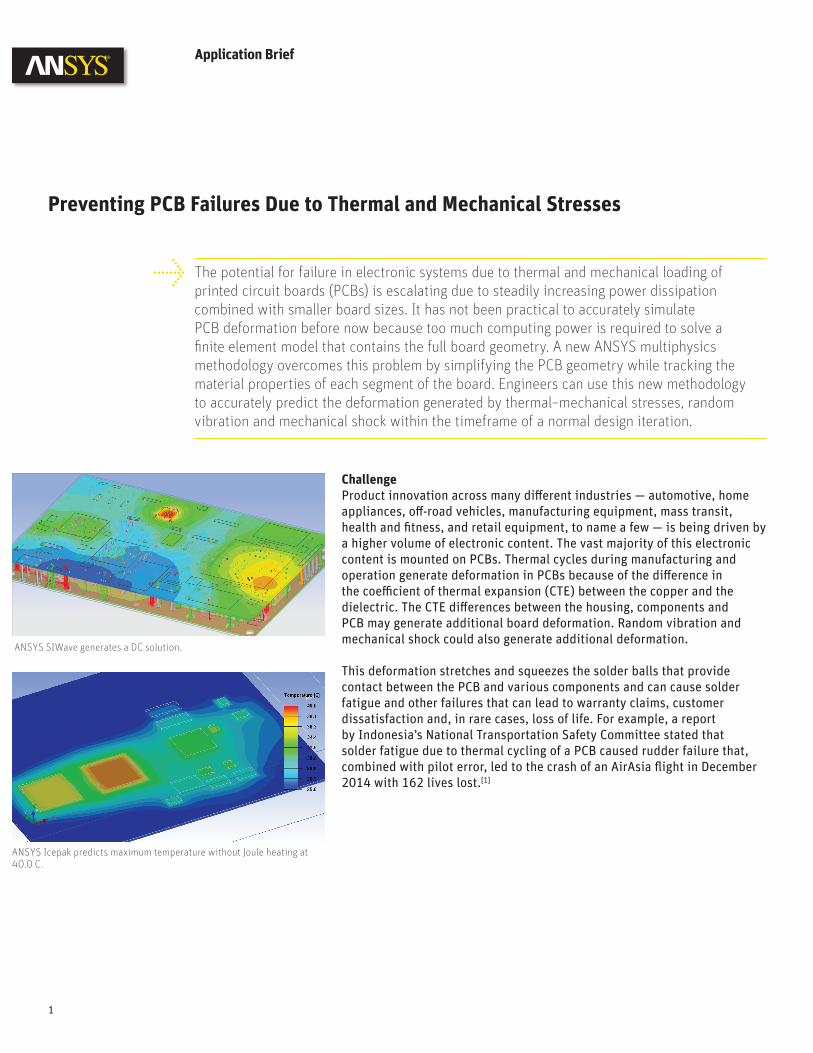
ANSYS SIWave generates a DC solution.
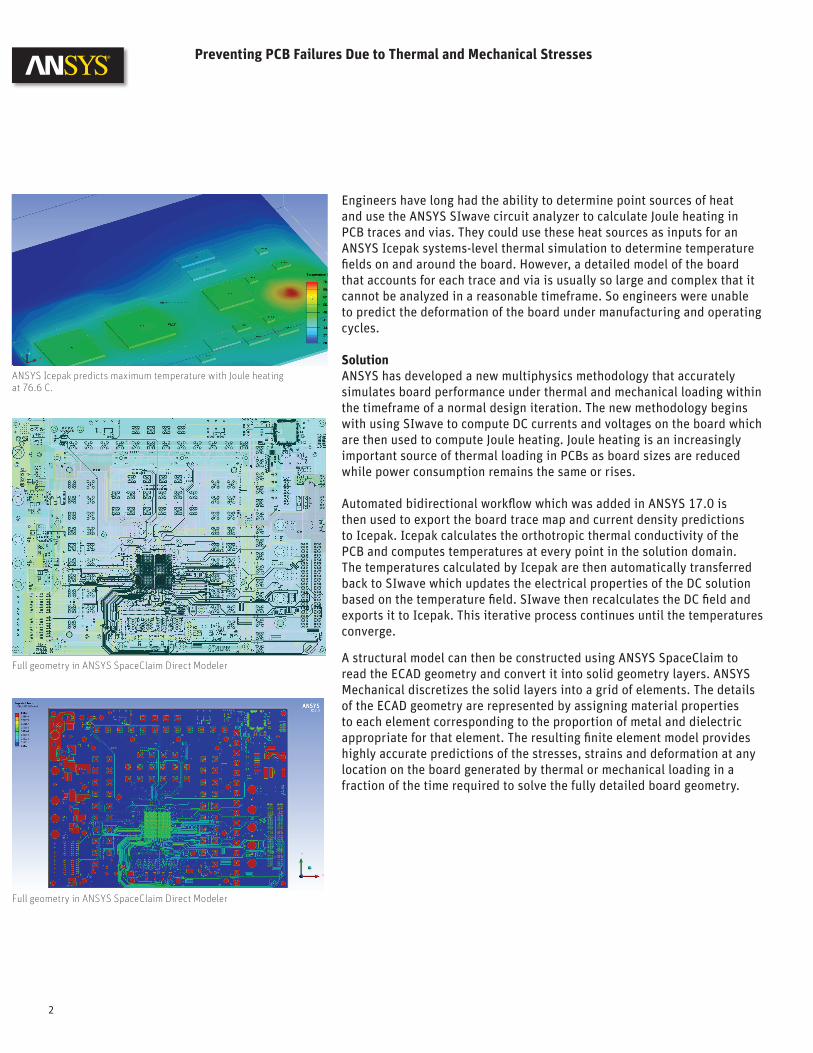
ANSYS Icepak predicts maximum temperature without Joule heating at 40.0 C.
Preventing PCB Failures Due to Thermal and Mechanical Stresses
Engineers have long had the ability to determine point sources of heat and use the ANSYS SIwave circuit analyzer to calculate Joule heating in PCB traces and vias. They could use these heat sources as inputs for an ANSYS Icepak systems-level thermal simulation to determine temperature fields on and around the board. However, a detailed model of the board that accounts for each trace and via is usually so large and complex that it cannot be analyzed in a reasonable timeframe. So engineers were unable to predict the deformation of the board under manufacturing and operating cycles.
SolutionANSYS has developed a new multiphysics methodology that accurately simulates board performance under thermal and mechanical loading within the timeframe of a normal design iteration. The new methodology begins with using SIwave to compute DC currents and voltages on the board which are then used to compute Joule heating. Joule heating is an increasingly important source of thermal loading in PCBs as board sizes are reduced while power consumption remains the same or rises.
Automated bidirectional workflow which was added in ANSYS 17.0 is then used to export the board trace map and current density predictions to Icepak. Icepak calculates the orthotropic thermal conductivity of the PCB and computes temperatures at every point in the solution domain. The temperatures calculated by Icepak are then automatically transferred back to SIwave which updates the electrical properties of the DC solution based on the temperature field. SIwave then recalculates the DC field and exports it to Icepak. This iterative process continues until the temperatures converge.
A structural model can then be constructed using ANSYS SpaceClaim to read the ECAD geometry and convert it into solid geometry layers. ANSYS Mechanical discretizes the solid layers into a grid of elements. The details of the ECAD geometry are represented by assigning material properties to each element corresponding to the proportion of metal and dielectric appropriate for that element. The resulting finite element model provides highly accurate predictions of the stresses, strains and deformation at any location on the board generated by thermal or mechanical loading in a fraction of the time required to solve the fully detailed board geometry.
2
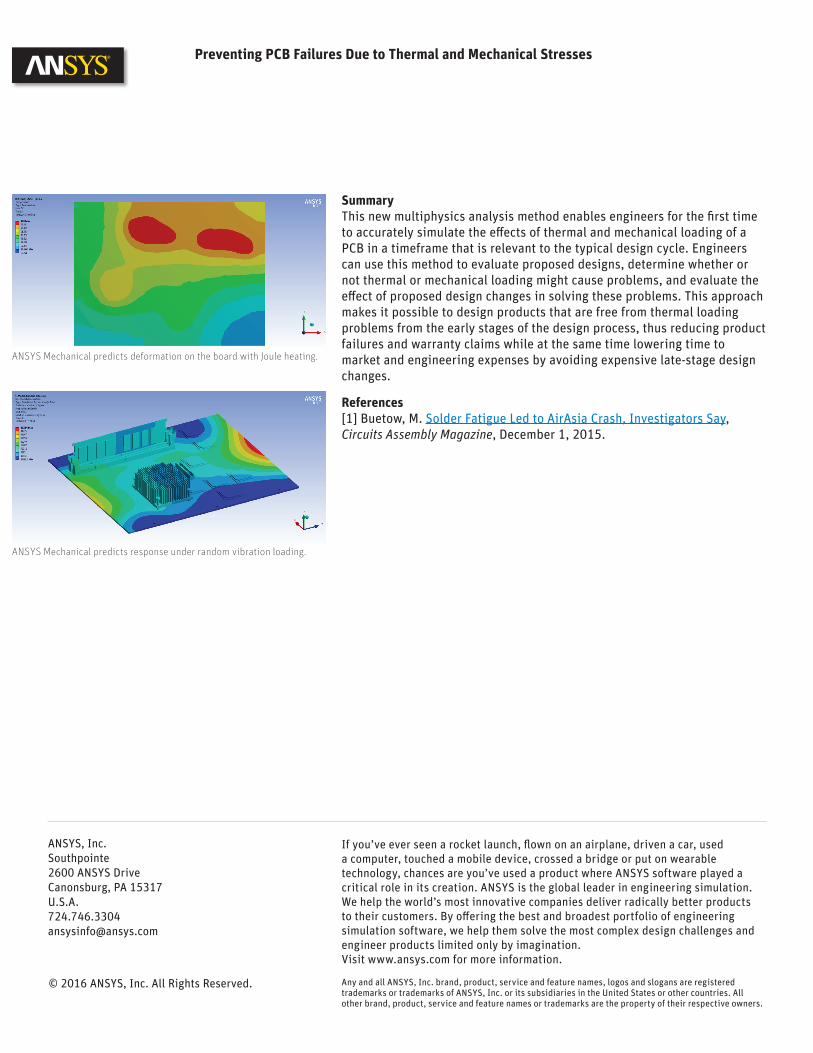
ANSYS Icepak predicts maximum temperature with Joule heating at 76.6 C.
Full geometry in ANSYS SpaceClaim Direct Modeler
Full geometry in ANSYS SpaceClaim Direct Modeler
SummaryThis new multiphysics analysis method enables engineers for the first time to accurately simulate the effects of thermal and mechanical loading of a PCB in a timeframe that is relevant to the typical design cycle. Engineers can use this method to evaluate proposed designs, determine whether or not thermal or mechanical loading might cause problems, and evaluate the effect of proposed design changes in solving these problems. This approach makes it possible to design products that are free from thermal loading problems from the early stages of the design process, thus reducing product failures and warranty claims while at the same time lowering time to market and engineering expenses by avoiding expensive late-stage design changes.
References[1] Buetow, M. Solder Fatigue Led to AirAsia Crash, Investigators Say, Circuits Assembly Magazine, December 1, 2015.
Preventing PCB Failures Due to Thermal and Mechanical Stresses
Any and all ANSYS, Inc. brand, product, service and feature names, logos and slogans are registered trademarks or trademarks of ANSYS, Inc. or its subsidiaries in the United States or other countries. All other brand, product, service and feature names or trademarks are the property of their respective owners.
© 2016 ANSYS, Inc. All Rights Reserved.
If you’ve ever seen a rocket launch, flown on an airplane, driven a car, used a computer, touched a mobile device, crossed a bridge or put on wearable technology, chances are you’ve used a product where ANSYS software played a critical role in its creation. ANSYS is the global leader in engineering simulation. We help the world’s most innovative companies deliver radically better products to their customers. By offering the best and broadest portfolio of engineering simulation software, we help them solve the most complex design challenges and engineer products limited only by imagination.Visit www.ansys.com for more information.
ANSYS, Inc.Southpointe2600 ANSYS DriveCanonsburg, PA [email protected]
ANSYS Mechanical predicts deformation on the board with Joule heating.
ANSYS Mechanical predicts response under random vibration loading.