preventa machine safety products - steven...
TRANSCRIPT

Preventa™ Machine Safety ProductsCatalog
20092010 Supplement
Safety Relay Modules
Courtesy of Steven Engineering, Inc.-230 Ryan Way, South San Francisco, CA 94080-6370-Main Office: (650) 588-9200-Outside Local Area: (800) 258-9200-www.stevenengineering.com

2 1Courtesy of Steven Engineering, Inc.-230 Ryan Way, South San Francisco, CA 94080-6370-Main Office: (650) 588-9200-Outside Local Area: (800) 258-9200-www.stevenengineering.com

2 1
Contents Safety automation solutionsPreventa™ safety relay modules
Selection guide 2
Electrical Ratings 6
Types XPSAC and XPSAXE For Emergency stop and switch monitoring 8
Types XPSAV, XPSABV and XPSATE For Emergency stop and switch monitoring 12
Types XPSBA, XPSBCE and XPSBF For electrical monitoring of two-hand control systems 22
Types XPSECME and XPSECP For increasing the number of safety contacts 30
Dimensions 34
Product ratings and levels Reliability values according to standards EN/ISO 13849-1 and EN/IEC 62061 36
Courtesy of Steven Engineering, Inc.-230 Ryan Way, South San Francisco, CA 94080-6370-Main Office: (650) 588-9200-Outside Local Area: (800) 258-9200-www.stevenengineering.com

2
Applications
Modules For Emergency stop and switch monitoring
Maximum achievable safety level PL e/Category 4 conforming to EN/ISO 13849-1SILCL 3 conforming to EN/IEC 62061
PL e/Category 4 conforming to EN/ISO 13849-1SILCL 3 conforming to EN/IEC 62061
PL e/Category 4 (instantaneous safety outputs) and PL d/Category 3 (time delay safety outputs) conforming to EN/ISO 13849-1,SILCL 3 (instantaneous safety outputs) and SILCL 2 (time delay safety outputs) conforming to EN/IEC 62061
PL e/Category 4 conforming to EN/ISO 13849-1, SILCL 3 conforming to EN/IEC 62061
PL e/Category 4 (instantaneous safety outputs) and PL d/Category 3 (time delay safety outputs) conforming to EN/ISO 13849-1, SILCL 3 (instantaneous safety outputs) and SILCL 2 (time delay safety outputs) conforming to EN/IEC 62061
Conformity to standards EN/IEC 60204-1,EN 1088/ISO 14119,EN/ISO 13850,EN/IEC 60947-1,EN/IEC 60947-5-1
EN/IEC 60204-1,EN 1088/ISO 14119,EN/ISO 13850,EN/IEC 60947-1,EN/IEC 60947-5-1
EN/IEC 60204-1,EN/ISO 13850,EN 1088/ISO 14119,EN/IEC 60947-1,EN/IEC 60947-5-1
EN/IEC 60204-1,EN 1088/ISO 14119,EN/ISO 13850,EN/IEC 60947-1,EN/IEC 60947-5-1
EN/IEC 60204-1,EN/IEC 60947-1,EN/IEC 60947-5-1,EN/ISO 13850,EN 1088/ISO 14119
Product certifications UL, CSA, TÜV UL, CSA, BG UL, CSA, TÜV UL, CSA, TÜV UL, CSA, BG
Number of circuitsSafety 3 N.O. 3 N.O. 2 N.O. instantaneous
+ 3 N.O. time delay3 N.O. instantaneous + 3 N.O. time delay
2 N.O. instantaneous + 1 N.O. time delay
Additional 1 solid-state output for signalling to PLC 1 relay output for signalling to PLC
4 solid-state outputs for signalling to PLC 3 solid-state outputs for signalling to PLC –
Display 2 LEDs 2 LEDs 4 LEDs 11 LEDs 3 LEDsSupply voltage a and 24 V c
48 V a115 V a230 V a
a and 24 V c a and 24 V c115 V a230 V a
24 V c 24 V c
Synchronisation time between inputs Unlimited Unlimited 75 ms (automatic start) Unlimited or 1.5 s (depending on wiring) UnlimitedInput channel voltage
24 V/48 V version a and 24 V c / 48 V a 24 V c / – 24 V c / – 24 V c / – 24 V c / –24 V/48 V or 110 V/120 V/230 V version
115 V a / 230 V–
– 48 V a / 48 V–
––
––
Module type XPSAC XPSAXE XPSATE XPSAV XPSABV
Pages 8 8 12 12 12
Selection guide Safety automation solutionsPreventa™ safety relay modules
Courtesy of Steven Engineering, Inc.-230 Ryan Way, South San Francisco, CA 94080-6370-Main Office: (650) 588-9200-Outside Local Area: (800) 258-9200-www.stevenengineering.com
3
Selection guide (continued) Safety automation solutionsPreventa™ safety relay modules
Applications
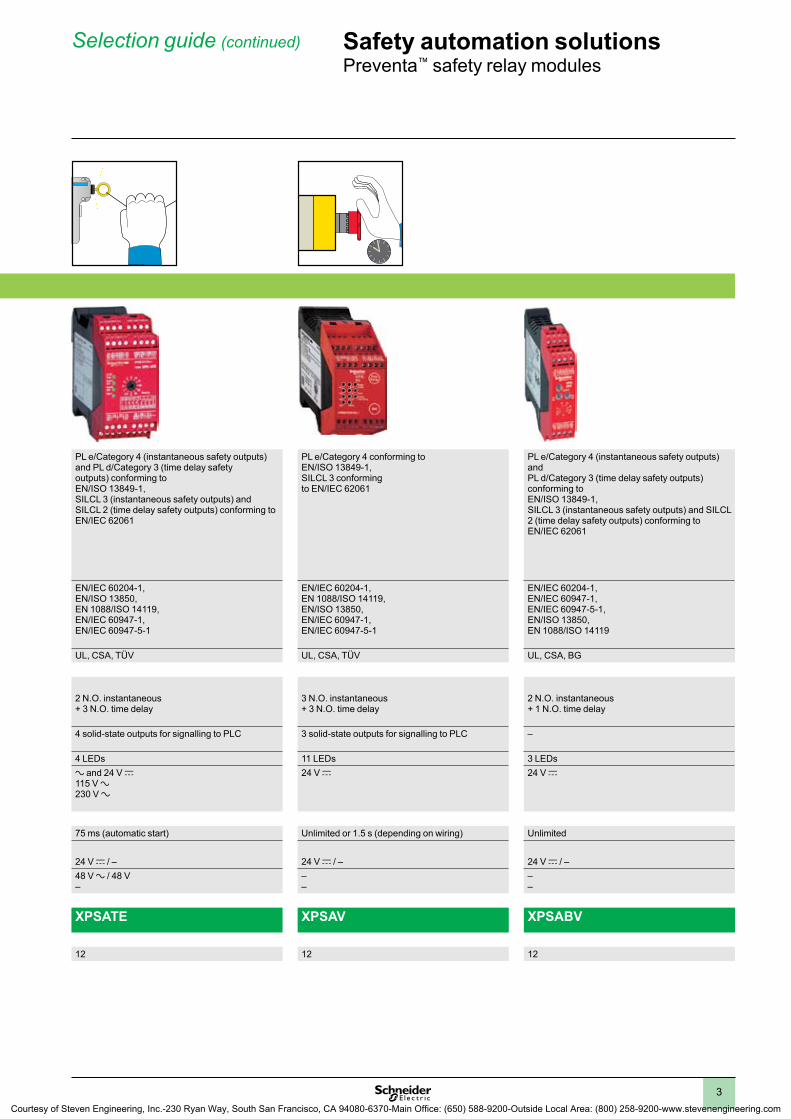
Modules For Emergency stop and switch monitoring
Maximum achievable safety level PL e/Category 4 conforming to EN/ISO 13849-1SILCL 3 conforming to EN/IEC 62061
PL e/Category 4 conforming to EN/ISO 13849-1SILCL 3 conforming to EN/IEC 62061
PL e/Category 4 (instantaneous safety outputs) and PL d/Category 3 (time delay safety outputs) conforming to EN/ISO 13849-1,SILCL 3 (instantaneous safety outputs) and SILCL 2 (time delay safety outputs) conforming to EN/IEC 62061
PL e/Category 4 conforming to EN/ISO 13849-1, SILCL 3 conforming to EN/IEC 62061
PL e/Category 4 (instantaneous safety outputs) and PL d/Category 3 (time delay safety outputs) conforming to EN/ISO 13849-1, SILCL 3 (instantaneous safety outputs) and SILCL 2 (time delay safety outputs) conforming to EN/IEC 62061
Conformity to standards EN/IEC 60204-1,EN 1088/ISO 14119,EN/ISO 13850,EN/IEC 60947-1,EN/IEC 60947-5-1
EN/IEC 60204-1,EN 1088/ISO 14119,EN/ISO 13850,EN/IEC 60947-1,EN/IEC 60947-5-1
EN/IEC 60204-1,EN/ISO 13850,EN 1088/ISO 14119,EN/IEC 60947-1,EN/IEC 60947-5-1
EN/IEC 60204-1,EN 1088/ISO 14119,EN/ISO 13850,EN/IEC 60947-1,EN/IEC 60947-5-1
EN/IEC 60204-1,EN/IEC 60947-1,EN/IEC 60947-5-1,EN/ISO 13850,EN 1088/ISO 14119
Product certifications UL, CSA, TÜV UL, CSA, BG UL, CSA, TÜV UL, CSA, TÜV UL, CSA, BG
Number of circuitsSafety 3 N.O. 3 N.O. 2 N.O. instantaneous
+ 3 N.O. time delay3 N.O. instantaneous + 3 N.O. time delay
2 N.O. instantaneous + 1 N.O. time delay
Additional 1 solid-state output for signalling to PLC 1 relay output for signalling to PLC
4 solid-state outputs for signalling to PLC 3 solid-state outputs for signalling to PLC –
Display 2 LEDs 2 LEDs 4 LEDs 11 LEDs 3 LEDsSupply voltage a and 24 V c
48 V a115 V a230 V a
a and 24 V c a and 24 V c115 V a230 V a
24 V c 24 V c
Synchronisation time between inputs Unlimited Unlimited 75 ms (automatic start) Unlimited or 1.5 s (depending on wiring) UnlimitedInput channel voltage
24 V/48 V version a and 24 V c / 48 V a 24 V c / – 24 V c / – 24 V c / – 24 V c / –24 V/48 V or 110 V/120 V/230 V version
115 V a / 230 V–
– 48 V a / 48 V–
––
––
Module type XPSAC XPSAXE XPSATE XPSAV XPSABV
Pages 8 8 12 12 12
Courtesy of Steven Engineering, Inc.-230 Ryan Way, South San Francisco, CA 94080-6370-Main Office: (650) 588-9200-Outside Local Area: (800) 258-9200-www.stevenengineering.com

4
Selection guide (continued) Safety automation solutionsPreventa™ safety relay modules
Applications
Modules For electrical monitoring of two-hand control stations
Maximum achievable safety level PL c/Category 1 conforming to EN/ISO 13849-1
PL e/Category 4 conforming to EN/ISO 13849-1, SILCL 3 conforming to EN/IEC 62061
PL e/Category 4 conforming to EN/ISO 13849-1,SILCL 3 conforming to EN/IEC 62061
Conformity to standards EN/IEC 60204-1,EN/IEC 60947-1,EN/IEC 60947-5-1,EN 574 type III A/ISO 13851
EN/IEC 60204-1,EN/IEC 60947-1,EN/IEC 60947-5-1,EN 574 type III C/ISO 13851
EN/IEC 60204-1,EN/IEC 60947-1,EN/IEC 60947-5-1,EN 574 type III C/ISO 13851
Product certifications UL, CSA, TÜV UL, CSA, BG UL, CSA, TÜV
Number of circuitsSafety 1 N.O. 2 N.O. 2 N.O.
Additional 1 N.C. 1 N.C. 2 solid-state outputs for signalling to PLC
Display 2 LEDs 3 LEDs 3 LEDs
Supply voltage a and 24 V c115 V a230 V a
a and 24 V c115 V a230 V a
24 V c
Synchronisation time between inputs 500 ms 500 ms 500 ms
Input channel voltage24 V/48 V version 24 V c / – 24 V c / – 24 V c / –115 V/230 V version 24 V a / 24 V – –
Module type XPSBA XPSBCE XPSBF
Pages 22 22 22
Courtesy of Steven Engineering, Inc.-230 Ryan Way, South San Francisco, CA 94080-6370-Main Office: (650) 588-9200-Outside Local Area: (800) 258-9200-www.stevenengineering.com

5
Applications
Modules For increasing the number of safety contacts
Functions Allows additional safety contacts to be added to another module
Maximum achievable safety level PL e/Category 4 conforming to EN/ISO 13849-1,SILCL 3 conforming to EN/IEC 62061 (when connected to the appropriate module)
PL e/Category 4 conforming to EN/ISO 13849-1, SILCL 3 conforming to EN/IEC 62061 (when connected to the appropriate module)
Conformity to standards EN/IEC 60204-1,EN 1088/ISO 14119,EN/ISO 13850,EN/IEC 60947-1,EN/IEC 60947-5-1
EN/IEC 60204-1,EN/IEC 60947-1,EN/IEC 60947-5-1
Product certifications UL, CSA, BG UL, CSA, TÜV
Number of circuitsSafety 4 N.O. 8 N.O.
Additional 2 N.C. outputs for signalling to PLC 1 N.C. + 1 solid-state output for signalling to PLC
Display 2 LEDs 3 LEDs
Supply voltage a and 24 V c a and 24 V c115 V a230 V a
Module type XPSECME XPSECP
Pages 30 30
Selection guide (continued) Safety automation solutionsPreventa™ safety relay modules
Courtesy of Steven Engineering, Inc.-230 Ryan Way, South San Francisco, CA 94080-6370-Main Office: (650) 588-9200-Outside Local Area: (800) 258-9200-www.stevenengineering.com

6
Electrical ratings Safety automation solutionsPreventa™ safety relay modules
Electrical lifeElectrical life curves of safety contacts conforming to EN 60947-5-1, table C2XPSAC, XPSTSA, XPSTSW, XPSBA, XPSCM, XPSOT, XPSPVK, XPSPVT, XPSVNE
XPSAXE, XPSECME
Sw
itchi
ng c
urre
nt (A
)
Number of operating cycles 0,1
1
10
Sw
itchi
ng c
urre
nt (A
)
Number of operating cycles
XPSEDA XPSECP
Number of operating cycles
Sw
itchi
ng c
urre
nt (A
)
Sw
itchi
ng c
urre
nt (A
)
Number of operating cycles
XPSATE24 V z version 115 V a + 230 V a version
DCDC
Sw
itchi
ng c
urre
nt (A
)
Number of operating cycles
AC
DC
100
10
1
Sw
itchi
ng c
urre
nt (A
)
Number of operating cycles
XPSAF, XPSAK, XPSAFL XPSAV, XPSMP, XPSVC, XPSBF, XPSMC
DC
Number of operating cycles
Sw
itchi
ng c
urre
nt (A
)
Number of operating cycles
Sw
itchi
ng c
urre
nt (A
)
XPSABVContacts 13-14, 23-24 Contacts 37-38
Number of operating cycles
0,1
1
10
Sw
itchi
ng c
urre
nt (A
)
0,1
1
10
Number of operating cycles
Sw
itchi
ng c
urre
nt (A
)
Courtesy of Steven Engineering, Inc.-230 Ryan Way, South San Francisco, CA 94080-6370-Main Office: (650) 588-9200-Outside Local Area: (800) 258-9200-www.stevenengineering.com

7
Electrical ratings (continued) Safety automation solutionsPreventa™ safety relay modules
Electrical life (continued)Electrical life curves of safety contacts conforming to EN 60947-5-1, table C2XPSBCE XPSAR
Number of operating cycles
0,1
1
10
Sw
itchi
ng c
urre
nt (A
) DCDC
Number of operating cycles
Sw
itchi
ng c
urre
nt (A
)
XPSDMB, XPSDME
DC
Sw
itchi
ng c
urre
nt (A
)
Number of operating cycles
Electrical lifeThe product life expressed is based on average usage and normal operating conditions. The above statements are not intended to nor shall they create any express or implied warranties as to product operation or life. For information on the limited warranty offered on this product please refer to the Square D terms and conditions of sale found in Square D’s Digest.
Definition of testsDetermination of electrical life conforming to EN 60947-5-1 (table C2)Type of current Utilization category Start-up Breaking
Current Voltage Cos j Current Voltage Cos ja c supply AC-15 10 x le Ue 0.7 le Ue 0.4Type of current Utilization category Start-up Breaking
Current Voltage T0 95 Current Voltage T0 95d c supply DC-13 le Ue 50 ms le Ue 50 ms
le: operational current measured. Ue: operational voltage measured. Cos j: power factor. T0.95: time taken to reach 95% of nominal current.
NotesThe tests are carried out with a frequency of 6 switching operations per minute and with no additional protection of the components connected to the safety outputs.The use of additional protection for the components connected to the safety outputs significantly increases the durability of the safety outputs.
Determination of the breaking capacity conforming to EN 60947-5-1 (table 4)Utilization category Start-up Breaking Total number
of switching operations
Switching operations per minute for 1 to 1000 switching operations
Switching operations per minute for 1001 to 6050 switching operations
Minimum duration of switching operation
Current Voltage Cos j Current Voltage Cos j
AC-15 10 x le Ue 0.3 le Ue 0.3 6050 60 6 50 msUtilization category Start-up Breaking Total number
of switching operations
Switching operations per minute for 1 to 1000 switching operations
Switching operations per minute for 1001 to 6050 switching operations
Minimum duration of switching operation
Current Voltage T0 95 Current Voltage T0 95
DC-13 le Ue 50 ms le Ue 50 ms 6050 60 6 50 ms
le: operational current measured. Ue: operational voltage measured. Cos j: power factor. T0.95: time taken to reach 95% of nominal current.NotesThe maximum values for the breaking capacity of the safety outputs in the various utilization categories are not fixed and depend on the power factor and on the switching frequency. The test definition for the “breaking capacity” and “durability” tables in the European standard EN 60947-5-1 uses different values for the power factor and the switching frequency.The power factor (cos j) in the “breaking capacity” table (0.3) is greater than that in the “durability” table (0.7).In the “breaking capacity” table, the switching frequency of the safety outputs is higher for the first 1000 switching operations (60 per minute) than that for 1001 to 6050 switching operations (6 per minute).Consequently, the maximum breaking capacity values determined using the “breaking capacity” table are lower than those in the “durability” table.
Courtesy of Steven Engineering, Inc.-230 Ryan Way, South San Francisco, CA 94080-6370-Main Office: (650) 588-9200-Outside Local Area: (800) 258-9200-www.stevenengineering.com

8
Operating principleSafety relay modules XPSAC and XPSAXE are used for monitoring Emergency stop circuits conforming to standards EN/ISO 13850 and EN/IEC 60204-1 and also meet the requirements for the electrical monitoring of switches in protection devices conforming to standard EN 1088/ISO 14119. They provide protection for both the machine operator and the machine by immediately stopping the dangerous movement on receipt of a stop instruction from the operator, or on detection of an anomaly in the safety circuit itself.To aid diagnostics, the modules have LEDs which provide information on the monitoring circuit status.
The XPSAC module has 3 safety outputs and a solid-state output for signalling to the PLC. The XPSAXE module has 3 safety outputs and a relay output for signalling to the PLC.
SpecificationsModule type XPSAC, XPSACppppP XPSAXEppppP, XPSAXEppppC
Maximum achievable safety level PL e/Category 4 conforming to EN/ISO 13849-1, SILCL 3 conforming to EN/IEC 62061
PL e/Category 4 conforming to EN/ISO 13849-1SILCL 3 conforming to EN/IEC 62061
Reliability data (1) Mean Time To dangerous Failure (MTTFd)
Years 210.4 457
Diagnostic Coverage (DC) % > 99 > 99Probability of dangerous Failure per Hour (PFHd)
1/h 3.56 x 10⁻⁹ 3 x 10⁻⁸
Conformity to standards EN/IEC 60204-1, EN 1088/ISO 14119,EN/ISO 13850, EN/IEC 60947-1, EN/IEC 60947-5-1
EN/IEC 60204-1, EN 1088/ISO 14119,EN/ISO 13850, EN/IEC 60947-1, EN/IEC 60947-5-1
Product certifications UL, CSA, TÜV UL, CSA, BGSupply Voltage V a and 24 c, 48 a, 115 a, 230 a a and 24 c
Voltage limits - 20 to + 10% (24 V a)- 20 to + 20% (24 V c)- 15 to + 10% (48 V a)- 15 to + 15 % (115 V)- 15 to + 10% (230 V)
- 15 to + 10%
Frequency Hz 50/60 50/60Power consumption W < 1.2 (24 V c) –
VA < 2.5 (24 V a)< 6 (48 V a)< 7 (115 V a)< 6 (230 V a)
< 1.6 (for 24VDC) / < 2.2 (for 24VAC)
Start button monitoring No NoControl unit voltage(at nominal supply voltage)
Identical to supply voltage24 V version V 24 a (approx. 90 mA), 24 c (approx. 40 mA) 24 c 48 V version V 48 a (approx. 100 mA) –115 V version V 115 a (approx. 60 mA) –230 V version V 230 a (approx. 25 mA) –
Outputs Voltage reference Relay hard contacts Relay hard contactsNumber and type of safety circuits 3 N.O. (13-14, 23-24, 33-34) 3 N.O. (13-14, 23-24, 33-34)Number and type of additional circuits
1 solid-state 1 N.C. relay (41-42)
Breaking capacity in AC-15 VA C300: inrush 1800, maintained 180 B300Breaking capacity in DC-13 24 V/2 A L/R = 50 ms 24 V/1.5 A L/R = 50 msMax. thermal current (Ithe) A 6 8/5 (N.O. / N.C.)Max. total thermal current A 10.5 12Output fuse protection, using fuses conforming to IEC/EN 947-5-1, DIN VDE 0660 part 200
A 4 gG (gl) or 6 fast acting 6gG
Minimum current mA 10 10Minimum voltage V 17 17
Electrical life See page 6Response time on input opening ms < 100 < 80Rated insulation voltage (Ui) V 300 (degree of pollution 2 conforming to IEC/EN 60947-5-1, DIN VDE 0110 parts 1 & 2)Rated impulse withstand voltage (Uimp) kV 3 (overvoltage category III, conforming
to IEC/EN 60947-5-1, DIN VDE 0110 parts 1 & 2)
4 (overvoltage category III, conforming to IEC/EN 60947-5-1, DIN VDE 0110 parts 1 & 2)
LED display 2 2Operating temperature °F (°C) + 14 to + 131 (- 10 to + 55) - 13 to +131 (- 25 to + 55)Storage temperature °F (°C) - 13 to +185 (- 25 to + 85) - 13 to +167 (- 25 to + 75)Degree of protection conforming to IEC/EN 60529
Terminals IP 20 IP 20Enclosure IP 40 IP 40
(1) Per EN/ISO 13849-1 and EN/IEC 62061
Operating principle, specifications
Safety automation solutionsPreventa™ safety relay modules types XPSAC, XPSAXEFor Emergency stop and switch monitoring
References: page 9
Wiring diagrams: page 10
Dimensions: page 34
Courtesy of Steven Engineering, Inc.-230 Ryan Way, South San Francisco, CA 94080-6370-Main Office: (650) 588-9200-Outside Local Area: (800) 258-9200-www.stevenengineering.com

9
Specifications (continued)Module type XPSAC XPSACppppP XPSAXEppppP XPSAXEppppC
Connection Type Terminals Captive screw clamp terminals
Captive screw clamp terminals
Captive screw clamp terminals
Spring terminals
Terminal block Integrated in module Removable from module
Removable from module
Removable from module
1-wire connection Without cable end Solid or flexible cable: 26-14 AWG (0.14 to 2.5 mm2)
Solid or flexible cable: 24-14 AWG (0.2 to 2.5 mm2)
With cable end Without bezel, flexible cable: 24-14 AWG (0.25 to 2.5 mm2)
With bezel, flexible cable: 24-16 AWG (0.25 to 1.5 mm2)
With bezel, flexible cable: 0.25 to 2.5 mm2)
With bezel, flexible cable: 24-16 AWG (0.25 to 1.5 mm2)
With bezel, flexible cable: 24-14 AWG (0.25 to 2.5 mm2)
2-wire connection Without cable end Solid or flexible cable: 26-20 AWG (0.14 to 0.75 mm2)
Solid cable: 24-18 AWG (0.2 to 1 mm2), flexible cable: 24-16 AWG (0.2 to 1.5 mm2)
Solid or flexible cable: 24-18 AWG (0.2 to 1 mm2)
–
With cable end Without bezel, flexible cable: 24-18 AWG (0.25 – 1.0 mm2) –Double, with bezel, flexible cable: 20-16 AWG (0.5 to 1.5 mm2) Double, with bezel,
flexible cable: 0-18 AWG (0.5 to 1 mm2)
ReferencesDescription Connection Number of
instantaneous opening safety circuits
Additional outputs
Supply Reference Weight oz (kg)
Safety modules for Emergency stop and switch monitoring
Captive screw clamp terminalsTerminal block integrated in module
3 1 solid-state a and 24 V c XPSAC5121 5.643(0.160)
48 V a XPSAC1321 7.408 (0.210)
115 V a XPSAC3421 7.408 (0.210)
230 V a XPSAC3721 7.408 (0.210)
Captive screw clamp terminals Terminal block removable from module
3 1 solid-state a and 24 V c XPSAC5121P 5.643(0.160)
48 V a XPSAC1321P 7.408 (0.210)
115 V a XPSAC3421P 7.408 (0.210)
230 V a XPSAC3721P 7.408 (0.210)
1 relay a and 24 V c XPSAXE5120P 8.078 (0.229)
Spring terminalsTerminal block removable from module
3 1 relay a and 24 V c XPSAXE5120C 8.078 (0.229)
XPSAXE5120P
XPSAXE5120C
XPSACppppP
XPSACpppp
Specifications (continued), references
Safety automation solutionsPreventa™ safety relay modules types XPSAC, XPSAXEFor Emergency stop and switch monitoring
Principle: page 8
Wiring diagrams: page 10
Dimensions: page 34
Courtesy of Steven Engineering, Inc.-230 Ryan Way, South San Francisco, CA 94080-6370-Main Office: (650) 588-9200-Outside Local Area: (800) 258-9200-www.stevenengineering.com

10
Wiring diagrams Safety automation solutions Preventa™ safety relay modules type XPSACFor Emergency stop and switch monitoring
XPSACModule XPSAC associated with an Emergency stop button with 1 N C contact
Logic
To PLC
Start
S1: Emergency stopS2: Start buttonY1-Y2: Feedback loop.ESC: External start conditions.
Module XPSAC associated with an Emergency stop button with 2 N C contacts (recommended application)
S2
S1K3
K4
K3
K4
K3
K4
K3
K4
A1 23 33Y2 13
A2 PE 14 24 34
Y43
Y44
Y1
F1
K2K148 V, 115 V 230 V
K1
K2T
ESC
K4K3
XPSAC
Logic
To PLC
Start
S1: Emergency stopS2: Start buttonY1-Y2: Feedback loop.ESC: External start conditions.
Functional diagram of module XPSAC
Key
Emergency stop activatedEmergency stop
not activated
Supply voltage
Emergency stop "A2" (02)
Output 23-24 (N.O.)
Emergency stop "A1" (01)
Feedback loop Y1-Y2
Start button not activated
Output 13-14 (N.O.)
Output 33-34 (N.O.)
Solid-state output Y43-Y44 (N.O.)
Start button activated
01
LED details
Constituants pour applications de sécurité
Modules de sécurité PREVENTApour surveillance d'Arrêt d'urgence
XPS-ALSignification des DEL
XPSALDEL-ILL-2-B
12
1 Tension d'alimentation A1-A22 Etat de K1-K2
1 Supply voltage A1-A2.2 K1-K2 status (N.O. safety outputs closed).
Principle: page 8
Specifications: page 8
References: page 9
Dimensions: page 34
Courtesy of Steven Engineering, Inc.-230 Ryan Way, South San Francisco, CA 94080-6370-Main Office: (650) 588-9200-Outside Local Area: (800) 258-9200-www.stevenengineering.com

11
Wiring diagrams (continued) Safety automation solutions Preventa™ safety relay modules type XPSAXEFor Emergency stop and switch monitoring
XPSAXEModule XPSAXE associated with an Emergency stop button with 1 N C contact
Logic
Start
S1: Emergency stopS2: StartY1-Y2: Feedback loopESC: External start conditions(1) Automatic reset(2) Maximum fuse rating: see page 8.
Module XPSAXE associated with an Emergency stop button with 2 N C contacts (recommended application)
Logic
Start
S1: Emergency stopS2: StartY1-Y2: Feedback loopESC: External start conditions(1) Automatic reset(2) Maximum fuse rating: see page 8.
Functional diagram of module XPSAXE
01
Emergency stop activatedEmergency stop
not activated
Supply voltage Start button not activated
Start button activated
Key
Emergency stop "A2" (02)
Output 23-24 (N.O.)
Emergency stop "A1" (01)
Feedback loop Y1-Y2/Y3
Output 13-14 (N.O.)
Output 33-34 (N.O.)
Solid-state output 41-42 (N.C.)
(1)
(1) Only for Emergency stop button with 2 N.C. contacts.
LED details
Constituants pour applications de sécurité
Modules de sécurité PREVENTApour surveillance d'Arrêt d'urgence
XPS-ALSignification des DEL
XPSALDEL-ILL-2-B
12
1 Tension d'alimentation A1-A22 Etat de K1-K2
1 Supply voltage A1-A2.2 K1-K2 status (N.O. safety outputs closed).
Principle: page 8
Specifications: page 8
References: page 9
Dimensions: page 34
Courtesy of Steven Engineering, Inc.-230 Ryan Way, South San Francisco, CA 94080-6370-Main Office: (650) 588-9200-Outside Local Area: (800) 258-9200-www.stevenengineering.com

12
References: page 14
Wiring diagrams: page 15
Dimensions: page 34
Operating principle, specifications
Safety automation solutionsPreventa™ safety relay modules types XPSAV, XPSABV, XPSATEFor Emergency stop and switch monitoring
Operating principleSafety relay modules XPSAV, XPSABV and XPSATE are used for monitoring Emergency stop circuits conforming to standards EN/ISO 13850 and EN/IEC 60204-1 and also meet the requirements for the electrical monitoring of switches in protection devices conforming to standard EN 1088 / ISO 14119.They provide protection for both the machine operator and the machine by immediately stopping the dangerous movement on receipt of a stop instruction from the operator, or on detection of an anomaly in the safety circuit itself.
In addition to the stop category 0 instantaneous opening safety outputs (3 for XPSAV, 2 for XPSABV and 2 for XPSATE), the modules incorporate stop category 1 time delay outputs (3 for XPSAV, 1 for XPSABV and 3 for XPSATE) which allow for controlled deceleration of the motor components until a complete stop is achieved (for example, motor braking by variable speed drive).
At the end of the preset delay, the supply is disconnected by opening the time delay output circuits.For module XPSAV, the time delay of the 3 output circuits is adjustable, in 15 preset values, between 0 and 300 seconds using selector buttons.For module XPSABV, the time delay of the output circuit is adjustable between 0.15 and 3 seconds or 1.5 and 30 seconds, depending on the model, using a selector switch.For module XPSATE, the time delay of the 3 output circuits is adjustable between 0 and 30 seconds using a 12-position selector switch. Module XPSAV also incorporates 3 solid-state signalling outputs for signalling to the process PLC. Module XPSATE incorporates 4 solid-state signalling outputs for signalling to the process PLC.To aid diagnostics, the modules have LEDs which provide information on the monitoring circuit status.
The Start button monitoring function is configurable depending on the wiring.
SpecificationsModule type XPSAV11113,
XPSAV11113PXPSABVppppC,XPSABVppppP
XPSATEpppp, XPSATEppppP
Maximum achievable safety level PL e/Category 4 conforming to EN/ISO 13849-1 SILCL 3 (instantaneous safety outputs and time delay safety outputs) conforming to EN/IEC 62061
PL e/Category 4 (instantaneous safety outputs) and PL d/Category 3 (time delay safety outputs) conforming to EN/ISO 13849-1, SILCL 3 (instantaneous safety outputs) and SILCL 2 (time delay safety outputs) conforming to EN/IEC 62061
PL e/Category 4 (instantaneous safety outputs) and PL d/Category 3 (time delay safety outputs) conforming to EN/ISO 13849-1,SILCL 3 (instantaneous safety outputs) and SILCL 2 (time delay safety outputs) conforming to EN/IEC 62061
Reliability data (1)(instantaneous safety outputs)
Mean Time To dangerous Failure (MTTFd)
Years 75.8 53 134.8
Diagnostic coverage (DC) % > 99 > 99 > 99Probability of dangerous Failure per Hour (PFHd)
1/h 7.95 x 10⁻⁹ 3 x 10⁻⁸ 6.81 x 10⁻⁹
Reliability data (1)(time delay safety outputs)
Mean Time To dangerous Failure (MTTFd)
Years 75.8 53 54.5
Diagnostic coverage (DC) % > 99 > 60 and < 90 98.4Probability of dangerous Failure per Hour (PFHd)
1/h 7.95 x 10⁻⁹ 2 x 10⁻⁷ 1.96 x 10⁻⁸
Conformity to standards EN/IEC 60204-1,EN/IEC 60947-1,EN/IEC 60947-5-1,EN/ISO 13850,EN 1088/ISO 14119,
EN/IEC 60204-1,EN/IEC 60947-1, EN/IEC 60947-5-1, EN/ISO 13850,EN 1088/ISO 14119
EN/IEC 60204-1,EN/IEC 60947-1,EN/IEC 60947-5-1,EN/ISO 13850,EN 1088/ISO 14119
Product certifications UL, CSA, TÜV UL, CSA, BG UL, CSA, TÜVSupply Voltage V 24 c 24 c a and 24 c, 115 a, 230 a
Voltage limits - 20 to + 20% - 15 to + 10% - 20 to + 10% (24 V) - 15 to + 15% (115 V) - 15 to + 10% (230 V)
Frequency Hz – – 50/60Power consumption W < 5 < 3 < 8Module inputs fuse protection Internal, electronicAdjustable time delay s 0 to 300 0.15 to 3 or 1.5 to 30 0 to 30Start button monitoring Yes/No (configurable by terminal wiring diagrams)Control unit voltage(at nominal supply voltage)
Between input terminals S21-S22, S31-S32 or S11-S12
Between input terminals S11-S12, S21-S22 or S11-S31
Between input terminals S11-S12, S21-S22 or S11-B1
24 V version V 24 24 24115 V, 230 V version V – 48
(1) Per EN/ISO 13849-1 and EN/IEC 62061
Courtesy of Steven Engineering, Inc.-230 Ryan Way, South San Francisco, CA 94080-6370-Main Office: (650) 588-9200-Outside Local Area: (800) 258-9200-www.stevenengineering.com

13
Principle: page 12
References: page 14
Wiring diagrams: page 15
Dimensions: page 34
Specifications (continued) Safety automation solutionsPreventa™ safety relay modules types XPSAV, XPSABV, XPSATEFor Emergency stop and switch monitoring
Specifications (continued)Module type XPS AV11113 AV11113P ABVppppP ABVppppC ATEpppp ATEppppP
Calculation of wiring resistance RL between input terminals W 100 max.Maximum cable length: 2000 m
RL = UeUn x 160-127
Ue = true voltage applied to terminals A1-A2Un = nominal supply voltage
RL max. =
U int - U min.I min.
Ue = true voltage applied to terminals A1-A2 U int (terminals S11-S21) = supply voltage Ue - 3 V (24 V version) U int between 42 V and 45 V, with typical value = 45 V (115 V, 230 V version) Calculated max. RL must be equal to or greater than the true value
Synchronization time between inputs s For guard: 1.5For Emergency stop: unlimited
< 0.5 Approx. 0.075For automatic start, terminals S33-Y2 and Y3-Y4 linked
Outputs Voltage reference Relay hard contactsNo. and type of instantaneous opening safety circuits 3 N.O. (03-04, 13-14, 23-24) 2 N.O. (13-14, 23-24) 2 N.O. (13-14, 23-24, 33-34)No. and type of time delay opening safety circuits 3 N.O. (37-38, 47-48, 57-58) 1 N.O. (37-38) 3 N.O. (57-58, 67-68, 77-78)Number and type of additional circuits 3 solid-state – 4 solid-stateBreaking capacity in AC-15
Instantaneous outputs
VA C300: inrush 1800, maintained 180
B300: inrush 3600, maintained 360
C300: inrush 1800, maintained 180
Time delay outputs VA C300: inrush 1800, maintained 180
B300: inrush 3600, maintained 360
C300: inrush 1800, maintained 180
Breaking capacity in DC-13
Instantaneous outputs
24 V/1.25 A L/R = 50 ms 24 V/1.5 A L/R = 50 ms 24 V/1.0 A L/R = 50 ms
Time delay outputs 24 V/1.25 A L/R = 50 ms 24 V/1.5 A L/R = 50 ms 24 V/1.0 A L/R = 50 msBreaking capacity of solid-state outputs 24 V/20 mA – –Max. thermal current (Ithe)
Instantaneous outputs
A 3.3 for all 3, or 6 for 1 and 2 for 2, or 4 for 2 and 2 for 1
6 5
Time delay outputs A 3.3 for all 3, or 6 for 1 and 2 for 2, or 4 for 2 and 2 for 1
6 2.5
Max. total thermal current A 20 12 8Output fuse protection, using fuses conforming to IEC/EN 60947-5-1, DIN VDE 0660 part 200
Instantaneous outputs
A 4 gG or 6 fast acting 6 gG 6 gG
Time delay outputs A 4 gG or 6 fast acting 6 gG 4 gG
Minimum current mA 10 (1) 10 10 (1)Minimum voltage V 17 (1) 17 17 (1)
Electrical life See page 6Response time on instantaneous opening inputs ms < 30 < 200 < 20Rated insulation voltage (Ui) V 300 (degree of pollution 2 conforming to IEC/EN 60947-5-1, DIN VDE 0110 parts 1 & 2)Rated impulse withstand voltage (Uimp) kV 4 (overvoltage category III, conforming to IEC/EN 60947-5-1, DIN VDE 0110 parts 1 & 2)LED display 11 3 4Operating temperature °F (°C) + 14 to + 131 (- 10 to + 55) - 13 to +131 (- 25 to + 55) + 14 to + 131 (- 10 to + 55)Storage temperature °F (°C) - 13 to +185 (- 25 to + 85) - 13 to +167 (- 25 to + 75) - 13 to +185 (- 25 to + 85)Degree of protectionconforming to IEC/EN 60529
Terminals IP 20Enclosure IP 40
Wiring diagrams Type of terminals Captive screw clamp terminals Spring terminals
Captive screw clamp terminals
Type of terminal block Integrated in module
Removable from module
1-wire connection Without cable end Solid or flexible cable: 26-14 AWG (0.14 to 2.5 mm2)
Solid or flexible cable: 24-14 AWG (0.2 to 2.5 mm2) Solid or flexible cable: 26-14 AWG (0.14 to 2.5 mm2)
Solid or flexible cable: 24-14 AWG (0.25 to 2.5 mm2)
With cable end Without bezel, flexible cable: 24-14 AWG (0.25 to 2.5 mm2)With bezel, flexible cable: 24-16 AWG (0.25 to 1.5 mm2)
With bezel, flexible cable: 24-14 AWG (0.25 to 2.5 mm2)
With bezel, flexible cable: 24-16 AWG (0.25 to 1.5 mm2)
With bezel, flexible cable: 24-14 AWG (0.25 to 2.5 mm2)
With bezel, flexible cable: 24-16 AWG (0.25 to 1.5 mm2)
With bezel, flexible cable: 24-14 AWG (0.25 to 2.5 mm2)
2-wire connection Without cable end Solid or flexible cable: 26-20 AWG (0.14 to 0.75 mm2)
Solid cable: 24-18 AWG (0.2 to 1 mm2)Flexible cable: 24-16 AWG (0.2 to 1.5 mm2)
Solid or flexible cable: 24-18 AWG (0.2 to 1 mm2)
– Solid or flexible cable: 26-20 AWG (0.14 to 0.75 mm2)
Solid cable: 24-18 AWG (0.2 to 1 mm2)Flexible cable: 24-16 AWG (0.2 to 1.5 mm2)
With cable end Without bezel, flexible cable: 24-18 AWG (0.25 to 1 mm2)
– Without bezel, flexible cable: 24-18 AWG (0.25 to 1 mm2)
Double, with bezel, flexible cable: 20-16 AWG (0.5 to 1.5 mm2)
Double, with bezel, flexible cable: 20-18 AWG (0.5 to 1 mm2)
Double, with bezel, flexible cable: 20-16 AWG (0.5 to 1.5 mm2)
(1) The module is also capable of switching low power loads (17 V/10 mA) provided that the contact has not been used for switching high power loads (possible contamination or wear of the gold layer on the contact tips).
Courtesy of Steven Engineering, Inc.-230 Ryan Way, South San Francisco, CA 94080-6370-Main Office: (650) 588-9200-Outside Local Area: (800) 258-9200-www.stevenengineering.com

14
References Safety automation solutionsPreventa™ safety relay modules types XPSAV, XPSABV, XPSATEFor Emergency stop and switch monitoring
ReferencesDescription Number of
safety circuits
Additional outputs
Setting range of time delay
Supply Connection Reference Weight
oz (kg)Safety modules for Emergency stop and switch monitoring
6 N.O. (3 N.O. time delay)
3 solid-state 0 to 300 s 24 V c Captive screw clamp terminalsTerminal block integrated in module
XPSAV11113 11.288 (0.320)
6 N.O. (3 N.O. time delay)
3 solid-state 0 to 300 s 24 V c Captive screw clamp terminalsTerminal block removable from module
XPSAV11113P 11.288 (0.320)
3 N.O. (1 N.O. time delay)
– 0.15 to 3 s 24 V c Captive screw clamp terminalsTerminal block removable from module
XPSABV1133P 9.877 (0.280)
24 V c Spring terminals Terminal block removable from module
XPSABV1133C 9.700 (0.275)
1.5 to 30 s 24 V c Captive screw clamp terminalsTerminal block removable from module
XPSABV11330P 9.877 (0.280)
24 V c Spring terminals Terminal block removable from module
XPSABV11330C 9.700 (0.275)
5 N.O. (3 N.O. time delay)
4 solid-state 0 to 30 s a/24 V c Captive screw clamp terminalsTerminal block integrated in module
XPSATE5110 9.877 (0.280)
Captive screw clamp terminalsTerminal block removable from module
XPSATE5110P 9.877 (0.280)
115 V a Captive screw clamp terminalsTerminal block integrated in module
XPSATE3410 13.404 (0.380)
Captive screw clamp terminalsTerminal block removable from module
XPSATE3410P 13.404 (0.380)
230 V a Captive screw clamp terminalsTerminal block integrated in module
XPSATE3710 13.404 (0.380)
Captive screw clamp terminalsTerminal block removable from module
XPSATE3710P 13.404 (0.380)
XPSABVppppP
XPSABVppppC
XPSAV11113
XPSAV11113P
XPSATE5110
Principle: page 12
Specifications: page 12
Wiring diagrams: page 15
Dimensions: page 34
Courtesy of Steven Engineering, Inc.-230 Ryan Way, South San Francisco, CA 94080-6370-Main Office: (650) 588-9200-Outside Local Area: (800) 258-9200-www.stevenengineering.com

15
Wiring diagrams Safety automation solutionsPreventa™ safety relay modules type XPSAVFor Emergency stop and switch monitoring
XPSAVModule XPSAV associated with an Emergency stop button with 1 N C contact, automatic start or unmonitored start
To PLC
Faul
t
Logicchannel 1
Logicchannel 2
Output 1
Output 2
Output 1
Output 2
Start
Time delay stop
Emergency stop
(1) Link for automatic start.(2) Instantaneous opening safety outputs (stop category 0).(3) Time delay opening safety outputs (stop category 1).ESC = External start conditions.
Functional diagramsAutomatic start Unmonitored start
Automatic startThere is no start contact or it is jumpered (wiring between terminals S13 - S14).Note: Automatic start function is not available on the XPSAV with 2 channel wiring on the inputs. Automatic start function is only available on single channel wiring on the inputs.
Unmonitored startThe output is activated on closing of the start contact.
Monitored startThe start input is monitored so that there is no start-up in the event of the start contact being jumpered or the start circuit being closed for more than 10 seconds.Start-up is triggered following activation of the start button (push-release function) on opening of the contact (wiring between terminals S33-S34).
Emergency stop S11-S12Automatic start (without ESC) S13-S14Linked input S21-S22Linked input S31-S32Time delay interrupt Y39-Y40N.O. output 03-04/13-14/23-24N.O. output 37-38/47-48/57-58Signalling output Y74Signalling output Y84
Emergency stop not activated
Power-upEmergency
stop activated
Emergency stop not activated
Emergency stop
activated
Start Start Time delay interrupted
Tv = 0 to 300 s
Emergency stop S11-S12Start button S13-S14Linked input S21-S22Linked input S31-S32Time delay interrupt Y39-Y40N.O. output 03-04/13-14/23-24N.O. output 37-38/47-48/57-58Signalling output Y74Signalling output Y84
Emergency stop not activated
Power-upEmergency stop
activatedEmergency
stop activated
Emergency stop not activated
Tv = 0 to 300 s Start Time delay interrupted
Start
Principle: page 12
Specifications: page 12
References: page 14
Dimensions: page 34
Courtesy of Steven Engineering, Inc.-230 Ryan Way, South San Francisco, CA 94080-6370-Main Office: (650) 588-9200-Outside Local Area: (800) 258-9200-www.stevenengineering.com

16
Wiring diagrams (continued) Safety automation solutionsPreventa™ safety relay modules type XPSAVFor Emergency stop and switch monitoring
XPSAVModule XPSAV associated with an Emergency stop button with 2 N C contacts, monitored start*
(1) Instantaneous opening safety outputs (stop category 0).(2) Time delay opening safety outputs (stop category 1).ESC = External start conditions.*Automatic start function is not available on the XPSAV with 2 channel wiring on the inputs. Automatic start function is only available on single channel wiring on the inputs.
Functional diagramMonitored start
Emergency stop monitoring function configuration1-channel wiring 2-channel wiring, with short-circuit detection
XPSAV
S1
A1 S11 S31 S32
A2 S21 S22
S12
XPSAV
S1
A1 S11 S31 S32
A2 S21 S22
S12
To PLC
Faul
t
Logic channel 1
Logic channel 2
Output 1
Output 2
Output 1
Output 2
Time delay stop
Emergency stop
Emergency stop
Start
Emergency stop not activated
Power-up
Emergency stop activated
Emergency stop not activated
Emergency stop activated
Start Start Time delay interrupted
Tv = 0 to 300 sNo start-up
Linked input S11-S12Emergency stop (channel 1) S21-S22Emergency stop (channel 2) S31-S32Start button S33-S34Time delay interrupt Y39-Y40N.O. output 03-04/13-14/23-24N.O. output 37-38/47-48/57-58Signalling output Y74Signalling output Y84
Principle: page 12
Specifications: page 12
References: page 14
Dimensions: page 34
Courtesy of Steven Engineering, Inc.-230 Ryan Way, South San Francisco, CA 94080-6370-Main Office: (650) 588-9200-Outside Local Area: (800) 258-9200-www.stevenengineering.com

17
XPSAVMonitoring of a movable guard associated with 2 switches Automatic start (diagram shown for guard closed)
(1) Instantaneous opening safety outputs (stop category 0).(2) Time delay opening safety outputs (stop category 1).ESC = External start conditions.
Functional diagram
LED details 1 S12 input status.
2 S22 input status.3 S32 input status.4 S34 input status.5 S14 input status.6 Y40 input status (time delay stop).7 K1/K2 status (N.O. instantaneous opening safety outputs).8 K3/K4 status (time delay opening safety outputs).9 Supply voltage A1-A2.10 Fault.11 Configuration mode.
To PLC
Faul
t
Logicchannel 1
Logicchannel 2
Output 1
Output 2
Output 1
Output 2
Guardclosed
Guardclosed
Time delay stop
1
5 6 7 8
234
91011
Linked input S11-S12Guard (channel 1) S21-S22Guard (channel 2) S31-S32Guard open S13-S14Time delay interrupt Y39-Y40N.O. output 03-04/13-14/23-24N.O. output 37-38/47-48/57-58Signalling output Y74Signalling output Y84
Power-up
Guard closed
Guard open
Guard closed
Guard open
Guard closed
Guard open
Start Time delay interrupted
Start Tv = 0 to 300 s
Wiring diagrams (continued) Safety automation solutionsPreventa™ safety relay modules type XPSAVFor Emergency stop and switch monitoring
Principle: page 12
Specifications: page 12
References: page 14
Dimensions: page 34
Courtesy of Steven Engineering, Inc.-230 Ryan Way, South San Francisco, CA 94080-6370-Main Office: (650) 588-9200-Outside Local Area: (800) 258-9200-www.stevenengineering.com

18
Wiring diagrams Safety automation solutionsPreventa™ safety relay modules type XPSABVFor Emergency stop and switch monitoring
XPSABVModule XPSAV associated with an Emergency stop button with 2 N C contacts, monitored start
A1
+ 24 V
F0
F1(3)
(1) (2)
S2 F2(3)
F3(3)
0 V
K1
S33 S34 S35 13 23 37
A2 S21 S11 S12 S31S22 14 24 38
K2
K3
K4
XPSABV
Feedback loop
Stop category 0
Reset
channel 1 channel 2 channel 2
Time (s)
Control logic
Supply
Stop category 0
Stop category 1
Safety outputs
S1: Emergency stopS2: Start buttonESC = External start conditions.(1) With start button monitoring.(2) Without start button monitoring or automatic
start.(3) Maximum fuse rating: see page 12.
Emergency stop or switch monitoring function configurations
S11 S12 S31 S33 S34 S21 S22
1
XPSABV
ON
1-channel Emergency stop, manual start
Start with S34 button monitoring
Jumper
XPSABV
S11 S12 S31 S33 S34 S21 S22
2
ON
Short-circuit monitoring 2-channel Emergency stop, manual start
Start with S34 button monitoring
Jumper
XPSABV
S11 S12 S21 S22 S33 S34 S11 S31
3
ON
Short-circuit monitoring 2-channel Emergency stop, manual start
Start with S34 button monitoring
Jumper
XPSABV
S11 S12 S21 S22 S33 S35 S11 S31
4
Machine guard with short-circuit monitoring, automatic start
Jumper or feedback loop for external contactors (automatic start S35)
Jumper
Principle: page 12
Specifications: page 12
References: page 14
Dimensions: page 34
Courtesy of Steven Engineering, Inc.-230 Ryan Way, South San Francisco, CA 94080-6370-Main Office: (650) 588-9200-Outside Local Area: (800) 258-9200-www.stevenengineering.com

19
Wiring diagrams (continued) Safety automation solutionsPreventa™ safety relay modules type XPSABVFor Emergency stop and switch monitoring
XPSABVFunctional diagrams
Emergency stop monitoring: configurations 1, 2 and 3 Power-up
Supply voltage (A1-A2)
tW
01
>tM >tM
tE1 tE1
tA >tA
tV
BeginEmergency stop not
activatedEmergency stop
activated
Begin
1. Channel (S11-S12)
2. Channel S21-S22 (S11-S31)
Falling edge start S33-S34
Rising edge start S33-S35
Output 13-14, 23-24 (N.O.)
Output 37-38 (N.O.)
tW: Recovery timetE: On-delaytm: Min. ON timetA: Response timetV: Off-delay (adjustable)tS: Synchronization time
Switch monitoring: configuration 4
tWtE2
tE2
tA tA
tV
tS
01
Supply voltage (A1-A2)
1. Channel (S11-S12)
2. Channel S21-S22 (S11-S31)
Rising edge start S33-S35
Output 13-14, 23-24 (N.O.)
Output 37-38 (N.O.)
Power-up Guard closed Guard open Guard closed
tW: Recovery timetE: On-delaytm: Min. ON timetA: Response timetV: Off-delay (adjustable)tS: Synchronization time
LED details
123 1 Supply voltage A1-A2
2 K1/K2 status3 K3/K4 status
Principle: page 12
Specifications: page 12
References: page 14
Dimensions: page 34
Courtesy of Steven Engineering, Inc.-230 Ryan Way, South San Francisco, CA 94080-6370-Main Office: (650) 588-9200-Outside Local Area: (800) 258-9200-www.stevenengineering.com

20
XPSATEModule XPSATE associated with an Emergency stop button*
Start
Logic
Stop category 0Instantaneous opening safety
outputs
Stop category 1Time delay
opening safety outputs
To PLC
S1: Emergency stop button with 2 N.C. contacts (recommended application).S2: Start button.ESC: External start conditions. Y1 (S33) - Y2: Feedback loop.F1: 4 A max.(1) With start button monitoring.(2) Without start button monitoring.(3) The outputs must be fuse protected. Technical specifications for maximum rating of fuses, see page 12.(4) a 115/230 V only.*For automatic start, jumper S2 (N.O. start button between terminals S33-Y1). This is only feasible when configured without start button monitoring (Y3 and Y4 jumpered). If S2 is jumpered and the module is configured for start button monitoring (Y3 and Y5 jumpered), the N.O. safety contacts will not close.
Functional diagram of module XPSATE with Emergency stop button monitoring
1 With start button monitoring (Y3-Y5 connection).2 Without start button monitoring (Y3-Y4 connection).
3 Without start button (connection Y3-Y4 and S33-Y1).Tv: adjustable time.
LED details
1234
1 Supply voltage A1-A2, internal electronic fuse status.2 S12 (A) input status.3 S22 (B) input status.4 Stop category 1 outputs closed.
2
3
1
01 Tv = 0…30 s
Tmax. = 75 ms
Supply voltage
Begin Emergency stopactivated
Emergency stop not activated
Emergency stop (O1)
Key
With Start button Solid-state output Y89 (S12)
Emergency stop (O2)
Solid-state output Y90 (S22)Start buttonStart button
Emergency stop (O2 or O1)Without Start button Solid-state output Y89 (S12)
Emergency stop (O2 or O1)
Solid-state output Y90 (S22)Start button
External start conditionsOutputs
Output 13-14 (N.O.)Output 23-24 (N.O.)
Output 57-58 (N.O.)Output 67-68 (N.O.)Output 77-78 (N.O.)
Solid-state output Y88 (A1/A2)Solid-state output Y91 (Stop 1)
Wiring diagrams Safety automation solutionsPreventa™ safety relay modules type XPSATEFor Emergency stop and switch monitoring
Principle: page 12
Specifications: page 12
References: page 14
Dimensions: page 34
Courtesy of Steven Engineering, Inc.-230 Ryan Way, South San Francisco, CA 94080-6370-Main Office: (650) 588-9200-Outside Local Area: (800) 258-9200-www.stevenengineering.com
21
Wiring diagrams (continued) Safety automation solutionsPreventa™ safety relay modules type XPSATEFor Emergency stop and switch monitoring
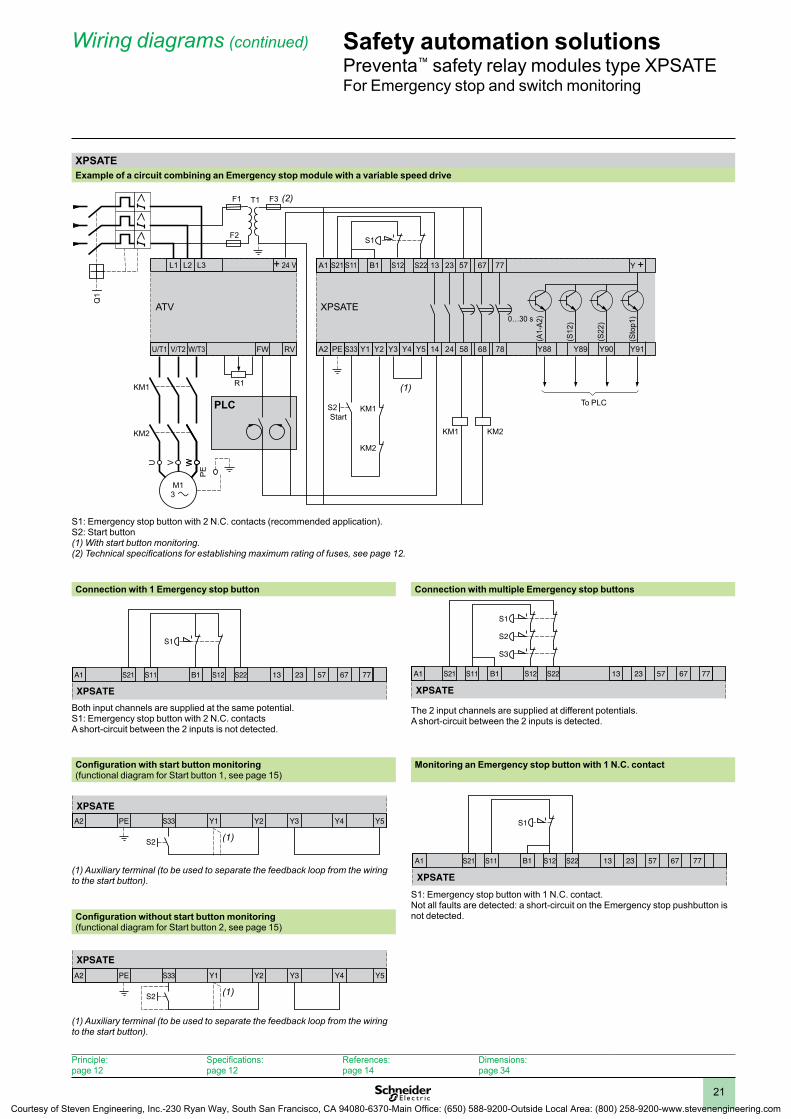
XPSATEExample of a circuit combining an Emergency stop module with a variable speed drive
S1: Emergency stop button with 2 N.C. contacts (recommended application).S2: Start button(1) With start button monitoring.(2) Technical specifications for establishing maximum rating of fuses, see page 12.
Connection with 1 Emergency stop button Connection with multiple Emergency stop buttons
Both input channels are supplied at the same potential.S1: Emergency stop button with 2 N.C. contacts A short-circuit between the 2 inputs is not detected.
The 2 input channels are supplied at different potentials. A short-circuit between the 2 inputs is detected.
Configuration with start button monitoring(functional diagram for Start button 1, see page 15)
Monitoring an Emergency stop button with 1 N C contact
(1) Auxiliary terminal (to be used to separate the feedback loop from the wiring to the start button).
S1: Emergency stop button with 1 N.C. contact.Not all faults are detected: a short-circuit on the Emergency stop pushbutton is not detected.Configuration without start button monitoring
(functional diagram for Start button 2, see page 15)
(1) Auxiliary terminal (to be used to separate the feedback loop from the wiring to the start button).
StartPLC To PLC
S11S21A1 13 77S22B1 S12 23 57 67
S1
XPSATE
S3
S11S21A1 13 77S22B1 S12 23 57 67
S2
S1
XPSATE
S2
A2 PE S33 Y1 Y2 Y3 Y4 Y5
XPSATE
(1)
S11S21A1 13 67 77S22B1 S12 23 57
S1
XPSATE
A2 PE S33 Y1 Y2 Y3 Y4 Y5
XPSATE
S2 (1)
Principle: page 12
Specifications: page 12
References: page 14
Dimensions: page 34
Courtesy of Steven Engineering, Inc.-230 Ryan Way, South San Francisco, CA 94080-6370-Main Office: (650) 588-9200-Outside Local Area: (800) 258-9200-www.stevenengineering.com

22
Operating principle Safety automation solutionsPreventa™ safety relay modules types XPSBA, XPSBCE, XPSBFFor electrical monitoring of two-hand control stations
Operating principleTwo-hand control stations are designed to provide protection against hand injury. They require machine operators to keep their hands clear of the hazardous movement zone.
The use of two-hand control is an individual protective measure, which can protect only one operator. Separate two-hand control stations must be provided for each operator in a multiple-worker environment. Safety relay modules XPSBA, BCE and BF for two-hand control stations comply with the requirements of European standard EN 574/ISO 13851 for two-hand control systems.
The control stations must be designed and installed such that they cannot be activated involuntarily or easily rendered inoperative. Depending on the application, the requirements of type C standards specific to the machinery involved must be met (additional personal protection methods may have to be considered).
To initiate a hazardous movement, both operators (two-hand control pushbuttons) must be activated within an interval y 0.5 s (synchronous activation). If one of the two pushbuttons is released during a hazardous operation, the control sequence is cancelled. Resumption of the hazardous operation is possible only if both pushbuttons are returned to their initial position and reactivated within the required time interval.
The control sequence does not occur if:• Both two-hand control push buttons are pressed during a time period greater than
0.5 seconds,• A short-circuit is present in a push button contact,• The feedback loop is not closed at start-up. The safety distance between the control units and the hazardous zone must be sufficient that when only one operator is released, the hazardous zone cannot be reached before the hazardous movement has been completed or stopped.
XPSBAThis module is designed for use on lighter duty applications where a two-hand control function is desired, but where the safety category is B or 1 (per EN 954-1) and the two-hand control requirements meet Type III A (per EN 574/ISO 13851). This module is not to be used for applications, such as presses, which require a Type III C module or where the application is not a category B or 1 For press applications, for applications in category 2, 3, or 4, or if application calls for a Type III C module, use XPSBCE or XPSBF module.
XPSBCE and XPSBFThese modules can be used on applications, such as presses, which require a Type III C module. The XPSBCE and XPSBF can be used for a two-hand control application, including presses and similar equipment.
Specifications: page 23
References: page 25
Wiring diagrams: page 26
Dimensions: page 34
Courtesy of Steven Engineering, Inc.-230 Ryan Way, South San Francisco, CA 94080-6370-Main Office: (650) 588-9200-Outside Local Area: (800) 258-9200-www.stevenengineering.com
23
Safety automation solutionsPreventa™ safety relay modules types XPSBA, XPSBCEFor electrical monitoring of two-hand control stations
Specifications
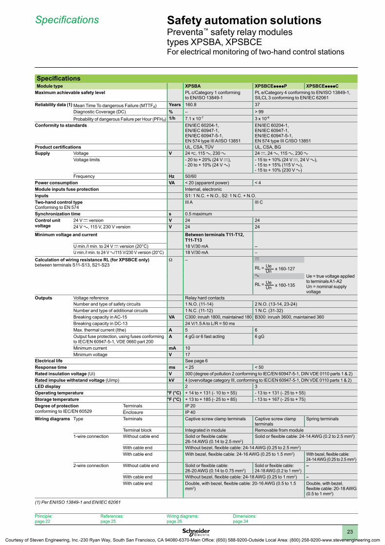
SpecificationsModule type XPSBA XPSBCEppppP XPSBCEppppC
Maximum achievable safety level PL c/Category 1 conforming to EN/ISO 13849-1
PL e/Category 4 conforming to EN/ISO 13849-1,SILCL 3 conforming to EN/IEC 62061
Reliability data (1) Mean Time To dangerous Failure (MTTFd) Years 160.8 37Diagnostic Coverage (DC) % – > 99Probability of dangerous Failure per Hour (PFHd) 1/h 7.1 x 10⁻⁷ 3 x 10⁻⁸
Conformity to standards EN/IEC 60204-1, EN/IEC 60947-1, EN/IEC 60947-5-1, EN 574 type III A/ISO 13851
EN/IEC 60204-1, EN/IEC 60947-1, EN/IEC 60947-5-1, EN 574 type III C/ISO 13851
Product certifications UL, CSA, TÜV UL, CSA, BGSupply Voltage V 24 z, 115 a, 230 a 24 c, 24 a, 115 a, 230 a
Voltage limits - 20 to + 20% (24 V c), - 20 to + 10% (24 V a)
- 15 to + 10% (24 V c, 24 V a),- 15 to + 15% (115 V a),- 15 to + 10% (230 V a)
Frequency Hz 50/60Power consumption VA < 20 (apparent power) < 4Module inputs fuse protection Internal, electronicInputs S1: 1 N.C. + N.O., S2: 1 N.C. + N.O.Two-hand control typeConforming to EN 574
III A III C
Synchronization time s 0.5 maximumControl unit voltage
24 V c version V 24 2424 V a, 115 V, 230 V version V 24 24
Minimum voltage and current Between terminals T11-T12, T11-T13
U min./I min. to 24 V c version (20°C) 18 V/30 mA –U min./I min. to 24 V a/115 V/230 V version (20°C) 18 V/30 mA –
Calculation of wiring resistance RL (for XPSBCE only)between terminals S11-S13, S21-S23
W – c
Ue = true voltage applied to terminals A1-A2Un = nominal supply voltage
RL = UeUn x 160-127
a
RL = UeUn x 160-135
Outputs Voltage reference Relay hard contactsNumber and type of safety circuits 1 N.O. (11-14) 2 N.O. (13-14, 23-24)Number and type of additional circuits 1 N.C. (11-12) 1 N.C. (31-32)Breaking capacity in AC-15 VA C300: inrush 1800, maintained 180 B300: inrush 3600, maintained 360Breaking capacity in DC-13 24 V/1.5 A to L/R = 50 msMax. thermal current (Ithe) A 5 6Output fuse protection, using fuses conforming to IEC/EN 60947-5-1, VDE 0660 part 200
A 4 gG or 6 fast acting 6 gG
Minimum current mA 10Minimum voltage V 17
Electrical life See page 6Response time ms < 25 < 50Rated insulation voltage (Ui) V 300 (degree of pollution 2 conforming to IEC/EN 60947-5-1, DIN VDE 0110 parts 1 & 2)Rated impulse withstand voltage (Uimp) kV 4 (overvoltage category III, conforming to IEC/EN 60947-5-1, DIN VDE 0110 parts 1 & 2)LED display 2 3Operating temperature °F (°C) + 14 to + 131 (- 10 to + 55) - 13 to + 131 (- 25 to + 55)Storage temperature °F (°C) + 13 to + 185 (- 25 to + 85) - 13 to + 167 (- 25 to + 75)Degree of protection conforming to IEC/EN 60529
Terminals IP 20Enclosure IP 40
Wiring diagrams Type Terminals Captive screw clamp terminals Captive screw clamp terminals
Spring terminals
Terminal block Integrated in module Removable from module1-wire connection Without cable end Solid or flexible cable:
26-14 AWG (0.14 to 2.5 mm2)Solid or flexible cable: 24-14 AWG (0.2 to 2.5 mm2)
With cable end Without bezel, flexible cable: 24-14 AWG (0.25 to 2.5 mm2)With cable end With bezel, flexible cable: 24-16 AWG (0.25 to 1.5 mm2) With bezel, flexible cable:
24-14 AWG (0.25 to 2.5 mm2)2-wire connection Without cable end Solid or flexible cable:
26-20 AWG (0.14 to 0.75 mm2)Solid or flexible cable: 24-18 AWG (0.2 to 1 mm2)
–
With cable end Without bezel, flexible cable: 24-18 AWG (0.25 to 1 mm2) –With cable end Double, with bezel, flexible cable: 20-16 AWG (0.5 to 1.5
mm2)Double, with bezel, flexible cable: 20-18 AWG (0.5 to 1 mm2)
(1) Per EN/ISO 13849-1 and EN/IEC 62061
Principle: page 22
References: page 25
Wiring diagrams: page 26
Dimensions: page 34
Courtesy of Steven Engineering, Inc.-230 Ryan Way, South San Francisco, CA 94080-6370-Main Office: (650) 588-9200-Outside Local Area: (800) 258-9200-www.stevenengineering.com

24
Specifications (continued) Safety automation solutionsPreventa™ safety relay modules type XPSBFFor electrical monitoring of two-hand control stations
SpecificationsModule type XPSBF1132 XPSBF1132P
Maximum achievable safety level PL e/Category 4 conforming to EN/ISO 13849-1, SILCL 3 conforming to EN/IEC 62061 Reliability data (1) Mean Time To dangerous Failure (MTTFd) Years 50.1
Diagnostic Coverage (DC) % > 99Probability of dangerous Failure per Hour (PFHd)
1/h 1.3 x 10⁻⁸
Conformity to standards EN 60204-1, EN 60947-1, EN 60947-5-1, EN 574 type III C/ISO 13851
Product certifications UL, CSA, TÜVSupply Voltage V 24 c
Voltage limits - 20 to + 20%
Power consumption W < 2.5Module inputs fuse protection Internal, electronicInputs S1: 1 N.C. + N.O., S2: 1 N.C. + N.O.Two-hand control type III C conforming to EN 574Synchronization time s 0.5 maximumControl unit voltage V 24 V/8 mA
Outputs Voltage reference Relay hard contactsNumber and type of safety circuits 2 N.O. (13-14, 23-24)Number and type of additional circuits 2 solid-state (type 24 V to 20 mA)Breaking capacity in AC-15 VA C300: inrush 1800, maintained 180Breaking capacity in DC-13 24 V/1.5 A to L/R = 50 msMax. thermal current (Ithe) A 4.2Max. total thermal current A 8.4Output fuse protection, using fuses conforming to IEC/EN 60947-5-1, VDE 0660 part 200
A 4 gG or 6 fast acting
Minimum current mA 10Minimum voltage V 17
Electrical life See page 6Response time ms < 20Rated insulation voltage (Ui) V 300 (degree of pollution 2 conforming to IEC/EN 60947-5-1, DIN VDE 0110 parts 1 & 2)Rated impulse withstand voltage (Uimp) kV 4 (overvoltage category III, conforming to IEC/EN 60947-5-1, DIN VDE 0110 parts 1 & 2)
LED display 3Operating temperature °F (°C) + 14 to + 131 (- 10 to + 55)Storage temperature °F (°C) -13 to +185 (- 25 to + 85)Degree of protection conforming to IEC/EN 60529
Terminals IP 20Enclosure IP 40
Connection Type Terminals Captive screw clamp terminals Captive screw clamp terminalsTerminal block Integrated in module Removable from module
1-wire connection Without cable end Solid or flexible cable: 26-14 AWG (0.14 to 2.5 mm2)
Solid or flexible cable: 24-14 AWG (0.2 to 2.5 mm2)
With cable end Without bezel, flexible cable: 24-14 AWG (0.25 to 2.5 mm2)
With cable end With bezel, flexible cable: 24-16 AWG (0.25 to 1.5 mm2)
With bezel, flexible cable: 24-14 AWG (0.25 to 2.5 mm2)
2-wire connection Without cable end Solid or flexible cable: 26-20 AWG (0.14 to 0.75 mm2)
Solid cable: 24-18 AWG (0.2 to 1 mm2), flexible cable: 24-16 AWG (0.2 to 1.5 mm2)
With cable end Without bezel, flexible cable: 24-18 AWG (0.25 to 1 mm2)
With cable end Double, with bezel, flexible cable: 20-16 AWG (0.5 to 1.5 mm2)
(1) Per EN/ISO 13849-1 and EN/IEC 62061
Principle: page 22
References: page 25
Wiring diagrams: page 26
Dimensions: page 34
Courtesy of Steven Engineering, Inc.-230 Ryan Way, South San Francisco, CA 94080-6370-Main Office: (650) 588-9200-Outside Local Area: (800) 258-9200-www.stevenengineering.com

25
Safety automation solutionsPreventa™ safety relay modules types XPSBA, XPSBCE, XPSBFFor electrical monitoring of two-hand control stations
Selection, references
SelectionRequirements of standard EN 574/ISO 13851
Type I Type II Type IIIA B C
Standard EN 574/ISO 13851 defines the selection of two-hand controls according to the control system category.The following table details the 3 types of two-hand control conforming to EN 574/ISO 13851.For each type, it lists the operating specifications and minimum requirements.
Use of both hands (simultaneous action)
Link between input and output signals
Output signal inhibited
Prevention of accidental operation
Tamper-proof
Output signal reinitialized
Synchronous action (specified time limit)
Use of proven components(Category 1 conforming to EN/ISO 13849-1)
XPSBApp
Redundancy with partial error detection (Category 3 conforming to EN/ISO 13849-1)
XPSBCEXPSBF
Redundancy + Self-monitoring(Category 4 conforming to EN/ISO 13849-1)
XPSBCEXPSBF
Meets the requirements of standard EN 574/ISO 13851
Conforming to standard EN/ISO 13849-1
ReferencesDescription Type
conforming to standard EN 574/ ISO 13851
Connection Number of safety circuits
Additional outputs
Supply Reference Weightoz (kg)
Safety modules for electrical monitoring of two-hand control stations
III A Captive screw clamp terminalsTerminal block integrated in module
1 N.O. 1 N.C. a or 24 V c
XPSBA5120 7.055 (0.200)
III C Captive screw clamp terminals Terminal block removable from module
2 N.O. 1 N.C. relay a and 24 V c
XPSBCE3110P 9.595 (0.272)
115 V a
XPSBCE3410P 11.358 (0.322)
230 V a
XPSBCE3710P 11.358 (0.322)
Spring terminalsTerminal block removable from module
2 N.O. 1 N.C. relay a and 24 V c
XPSBCE3110C 9.595 (0.272)
115 V a
XPSBCE3410C 11.358 (0.322)
230 V a
XPSBCE3710C 11.358 (0.322)
Captive screw clamp terminals Terminal block removable from module
2 N.O. 2 solid-state 24 V c
XPSBF1132 5.291 (0.150)
2 N.O. 2 solid-state 24 V c
XPSBF1132P 5.291 (0.150)
XPSBCEppppP XPSBCEppppC
XPSBA5120
XPSBF1132
Principle: page 22
Specifications: page 23
Wiring diagrams: page 26
Dimensions: page 34
Courtesy of Steven Engineering, Inc.-230 Ryan Way, South San Francisco, CA 94080-6370-Main Office: (650) 588-9200-Outside Local Area: (800) 258-9200-www.stevenengineering.com

26
Wiring diagrams Safety automation solutionsPreventa™ safety relay modules type XPSBAFor electrical monitoring of two-hand control stations
XPSBAModule XPSBA associated with a two-hand control station
Type III A conforming to EN 574/ISO 13851
S1 and S2: pushbuttons. Must not be used for applications (presses) which require a type III C module (XPSBCE or XPSBF).
Functional diagram of module XPSBA
LED details (XPSBA)
1 Supply voltage A1-A2.2 K1 status (N.O. safety output 11-14 closed).
A1 T13 11
A2 12 14
T11T11 T12
F1
L1 (+)
N (–)
T
S2
S1
XPSBA
K1+–
Logic
Signalling output Safety output
01
Button1
Two-hand control not activated
max. 500 ms
Supply voltage
Key
Two-hand control activated
Two-hand control not activated
max. 25 ms
Response time
Supply A1-A2
InputT11-T12 (N.C.)
InputT11-T13 (N.O.)
Safety output 11-14 (N.O.)
Signalling output 11-12 (N.C.)
Button2
12
Principle: page 22
Specifications: page 23
References: page 25
Dimensions: page 34
Courtesy of Steven Engineering, Inc.-230 Ryan Way, South San Francisco, CA 94080-6370-Main Office: (650) 588-9200-Outside Local Area: (800) 258-9200-www.stevenengineering.com

27
Safety automation solutionsPreventa™ safety relay modules type XPSBCEFor electrical monitoring of two-hand control stations
Wiring diagrams
XPSBCEModule XPSBCE associated with a two-hand control station
Type III C conforming to EN 574/ISO 13851a and 24 V c
Logic
S1, S2: Two-hand control station pushbuttonsESC: External start conditions(1) Maximum fuse rating: see page 23.
115 a and 230 V
A1 S13
S2
23 31Y2 13
A2 S11 S21 14 24 32
S12S22 S23 Y1
F1L (+)
PE
N (-)
T
ESCS1
K4
K4
K3
K3
K2
K2
K1
K2
K1
K1
24 V
XPSBCE
(1) (1)
t
Logic
S1, S2: Two-hand control station pushbuttonsESC: External start conditions(1) Maximum fuse rating: see page 23.
Principle: page 22
Specifications: page 23
References: page 25
Dimensions: page 34
Courtesy of Steven Engineering, Inc.-230 Ryan Way, South San Francisco, CA 94080-6370-Main Office: (650) 588-9200-Outside Local Area: (800) 258-9200-www.stevenengineering.com

28
Wiring diagrams (continued) Safety automation solutionsPreventa™ safety relay modules type XPSBCEFor electrical monitoring of two-hand control stations
XPSBCE (continued)Functional diagram of module XPSBCE
10
trts
Key
Button 1
Two-hand control not activated Two-hand control activated Two-hand control deactivated
Button 2
Mushroom head S1 (N.C.)
Mushroom head S1 (N.O.)
Mushroom head S2 (N.C.)
Mushroom head S2 (N.O.)
Feedback loop Y1-Y2
Output 13-14 (N.O.)
Output 23-24 (N.O.)
Output 31-32 (N.C.)
ts, Synchronization time: 500 ms max.tr, Response time: 50 ms.
LED details (XPSBCE)
123 1 Supply voltage A1-A2.
2 K1 status (N.O. safety outputs closed).3 K2 status (N.O. safety outputs closed).
Principle: page 22
Specifications: page 23
References: page 25
Dimensions: page 34
Courtesy of Steven Engineering, Inc.-230 Ryan Way, South San Francisco, CA 94080-6370-Main Office: (650) 588-9200-Outside Local Area: (800) 258-9200-www.stevenengineering.com

29
Wiring diagrams Safety automation solutionsPreventa™ safety relay modules type XPSBFFor electrical monitoring of two-hand control stations
XPSBFModule XPSBF associated with a two-hand control station
ESC: External start conditions. Y1-Y2: feedback loop
Functional diagram of module XPSBF
LED details (XPSBF)
1 Supply voltage A1-A2 (fuse status).2 Fault signalling.3 K1-K2 status (N.O. safety outputs closed).
A1 S12 23Y2 13
A2 S22 S23 Y34 Y44S21 14 24
S13S11 Y1
F1
K2
K1K1/K2
K1
K2
K4K3
K1/K2
K3
K4ESCS1
XY2 SB
XY2 SB S2
XPSBF
To PLC
FaultLogic
Button1
Button2
Two-hand control deactivated
Two-hand control activatedTwo-hand control not activated
Mushroom head S1 (N.O.)
Mushroom head S1 (N.C.)
Mushroom head S2 (N.C.)
Mushroom head S2 (N.O.)
Feedback loop
Output 13-14 (N.O.)
Output 23-24 (N.O.)
Solid-state output Y34 (fault)
Key
T1 = 0.5 s max. T2 = 0.02 s max.
Solid-state output Y44 (K1/K2)
Activated Deactivated
123
Principle: page 22
Specifications: page 23
References: page 25
Dimensions: page 34
Courtesy of Steven Engineering, Inc.-230 Ryan Way, South San Francisco, CA 94080-6370-Main Office: (650) 588-9200-Outside Local Area: (800) 258-9200-www.stevenengineering.com

30
Operating principleSafety relay modules XPSECME and XPSECP, for increasing the number of safety contacts, are available as additions to Preventa™ XPS base modules (Emergency stop, limit switch, two-hand control, etc.). They are used to increase the number of safety output contacts of the base modules.
SpecificationsModule type XPSECMEppppP XPSECMEppppC XPSECPpppp
Maximum achievable safety level PL e/Category 4 conforming to EN/ISO 13849-1, SILCL 3 conforming to EN/IEC 62061 (when connected to the appropriate module)
PL e/Category 4 conforming to EN/ISO 13849-1 SILCL 3 conforming to EN/IEC 62061 (when connected to the appropriate module)
Reliability data (1) Mean Time To dangerous Failure (MTTFd) Years 100 346.2
Diagnostic Coverage (DC) % 60 to 90 0 to 99
Probability of dangerous Failure per Hour (PFHd) 1/h 2 x 10⁻⁷ 7.51 x 10⁻⁹
Conformity to standards EN/IEC 60204-1,EN/IEC 60947-1,EN/IEC 60947-5-1
EN/IEC 60204-1, EN/IEC 60947-1,EN/IEC 60947-5-1
Product certifications UL, CSA, BG UL, CSA, TÜVSupply Voltage V a and 24 c a and 24 c, 115 a, 230 a
Voltage limits - 15 to + 10% - 20 to + 10% (24 V a),- 20 to + 20% (24 V c),- 15 to + 15% (115 V a),- 15 to + 10% (230 V a)
Frequency Hz 50/60Power consumption 24 V VA < 5 < 5
115 V/230 V VA – < 6Module inputs fuse protection Internal, electronicOutputs Voltage reference Relay hard contacts
Number and type of safety circuits 4 N.O. (13-14, 23-24, 33-34, 43-44) 8 N.O. (13-14, 23-24, 33-34, 43-44, 53-54, 63-64, 73-74, 83-84)
Number and type of additional circuits 2 N.C. (51-52, 61-62) 1 N.C. (91-92) + 1 solid-stateBreaking capacity in AC-15 VA B300: inrush 3600, maintained 360Breaking capacity in DC-13 24 V/1.5 A to L/R = 50 msBreaking capacity of solid-state outputs 24 V/20 mA, 48 V/10 mAMax. thermal current (Ithe) A 6Max. total thermal current A 12 30Output fuse protection A 6 gGMinimum current (relay contact) mA 10 (conforming to EN/IEC 60947-5-1, VDE 0660 part 200)Minimum voltage (relay contact) V 17
Electrical life See page 6Response time on input opening ms < 20Rated insulation voltage (Ui) V 300 (degree of pollution 2 conforming to IEC/EN 60947-5-1, DIN VDE 0110 parts 1 & 2)Rated impulse withstand voltage (Uimp) kV 4 (overvoltage category III, conforming to IEC/EN 60947-1, DIN VDE 0110 parts 1 & 2)LED display 2 3Operating temperature °F (°C) - 13 to + 131 (- 25 to + 55) + 14 to +131 (- 10 to + 55)Storage temperature °F (°C) - 13 to + 167 (- 25 to + 75) - 13 to + 185 (- 25 to + 85)Degree of protection conforming to IEC 60529
Terminals IP 20Enclosure IP 40
Connection Type Terminals Captive screw clamp terminals
Spring terminals Captive screw clamp terminals
Terminal block Removable from module Integrated in module1-wire connection Without cable end Solid or flexible cable: 24-14 AWG (0.2 to 2.5 mm2) 1 x 12 AWG (4 mm2)
With cable end Without bezel, flexible cable: 24-14 AWG (0.25 to 2.5 mm2) 2 x 14 AWG (2.4 mm2)With bezel, flexible cable: 24-16 AWG (0.25 to 1.5 mm2)
With bezel, flexible cable: 24-14 AWG (0.25 to 2.5 mm2)
–
2-wire connection Without cable end Solid or flexible cable: 24-18 AWG (0.2 to 1 mm2)
– –
With cable end Without bezel, flexible cable: 24-18 AWG (0.25 to 1 mm2)
– –
Double, with bezel, flexible cable: 20-16 AWG (0.5 to 1.5 mm2)
Double, with bezel, flexible cable: 20-18 AWG (0.5 to 1 mm2)
–
(1) Per EN/ISO 13849-1 and EN/IEC 62061
Safety automation solutionsPreventa™ safety relay modules types XPSECME, XPSECPFor increasing the number of safety contacts
Operating principle, specifications
References: page 31
Wiring diagrams: page 32
Dimensions: page 34
Courtesy of Steven Engineering, Inc.-230 Ryan Way, South San Francisco, CA 94080-6370-Main Office: (650) 588-9200-Outside Local Area: (800) 258-9200-www.stevenengineering.com

31
ReferencesDescription Number
of safety circuits
Additional outputs
Solid-state outputs for PLC
Supply Connection Reference Weight oz (kg)
Safety modules for increasing the number of safety contacts, for use with XPS base modules
4 2 – a and 24 V c Captive screw clamp terminalsTerminal block removable from module
XPSECME5131P 9.524 (0.270)
a and 24 V c Spring terminals Terminal block removable from module
XPSECME5131C 9.524 (0.270)
8 1 1 a and 24 V c Captive screw clamp terminalsTerminal block integrated in module
XPSECP5131 19.401 (0.550)
115 V a Captive screw clamp terminalsTerminal block integrated in module
XPSECP3431 22.928 (0.650)
230 V a Captive screw clamp terminalsTerminal block integrated in module
XPSECP3731 22.928 (0.650)
References Safety automation solutionsPreventa™ safety relay modules types XPSECME, XPSECPFor increasing the number of safety contacts
XPSECME5131P
XPSECME5131C
XPSECPpppp
Principle: page 30
Specifications: page 30
Wiring diagrams: page 32
Dimensions: page 34
Courtesy of Steven Engineering, Inc.-230 Ryan Way, South San Francisco, CA 94080-6370-Main Office: (650) 588-9200-Outside Local Area: (800) 258-9200-www.stevenengineering.com

32
XPSECMEWiring diagram
A2
F1L (+)z 24 V
N (–)
A1 Y1 13
Y2 14
13
Y1Y214
K1
K2
23
24
33
34
43
44
51
52
61
62
XPS
XPSECME
Base module
4 safety outputs
2 signalling outputs
Functional diagram
01
Relay K1/K2 deactivated
Base module deactivated
Relay K1/K2
Key
Feedback loop Y1-Y2
Signalling output51-52 (N.C.)
Output 13-14 (N.O.)
Relay K1/K2 activated
Base module activated
Output 23-24 (N.O.)
Output 33-34 (N.O.)
Output 43-44 (N.O.)
Signalling output61-62 (N.C.)Base module A1/A2Fuse
Wiring diagrams Safety automation solutionsPreventa™ safety relay modules type XPSECMEFor increasing the number of safety contacts
Principle: page 30
Specifications: page 30
References: page 31
Dimensions: page 34
Courtesy of Steven Engineering, Inc.-230 Ryan Way, South San Francisco, CA 94080-6370-Main Office: (650) 588-9200-Outside Local Area: (800) 258-9200-www.stevenengineering.com

33
XPSECPWiring diagram
(1) When installing base modules and modules for increasing the number of safety contacts into different electrical enclosures, run separate cables for terminals U1-13 and U1-23.
(2) Operating status of internal electronic fuse.
Functional diagram
A2 PE
F1L (+)
N (–)
T – +
XPSECPA1
115 V230 V
U1 K1 Y1K2 U2 13
Y2 14
Y03
Y04
A1/A2
K1
B1
K2
K1
K2
23
24
33
34
43
44
53
54
63
64
73
74
83
84
91
92
13
Y1Y2
23
14 24
(2)
(1)
XPSBase module
Safety outputsSignalling
output
To PLC
Fuse
01
Input A (U1-K1)Input B (U2-K2)Feedback loop Y1-Y2
Output 13-14 (N.O.)
Sortie 23-24 (N.O.)
Sortie 33-34 (N.O.)
Sortie 43-44 (N.O.)
Channel 2 opens
Channel 2 closes
Channel 1 closes
Supply voltage Channel 1 opens
Sortie 53-54 (N.O.)
Sortie 63-64 (N.O.)
Sortie 73-74 (N.O.)
Sortie 83-84 (N.O.)Signalling output 91-92 (N.C.)Solid-state output A1/A2 (fuse)
Key
Safety automation solutionsPreventa™ safety relay modules type XPSECPFor increasing the number of safety contacts
Wiring diagrams
Principle: page 30
Specifications: page 30
References: page 31
Dimensions: page 34
Courtesy of Steven Engineering, Inc.-230 Ryan Way, South San Francisco, CA 94080-6370-Main Office: (650) 588-9200-Outside Local Area: (800) 258-9200-www.stevenengineering.com

34
Dimensions Safety automation solutionsPreventa™ safety relay modulesAM1 DP200 rail mounting
DimensionsXPSACpppp, XPSAFpppp, XPSAFLpppp, XPSDMBpppp, XPSVCpppp, XPSEDA
XPSACppppP, XPSABVppppP, XPSAXEppppP, XPSAFpppP, XPSAFLppppP, XPSBCEppppP, XPSBFppppP, XPSECMEppppP, XPSDMBppppP, XPSVCppppP
22,5
99
114 22,5114
99
XPSABVppppC, XPSAXEppppC, XPSBCEppppC, XPSECMEppppC
XPSAKpppp, XPSAVpppp, XPSCMpppp, XPSDMEpppp, XPSATEpppp
4.49114
1.7745
3.9099
XPSAKppppP, XPSAVppppP, XPSCMppppP, XPSTSApppP, XPSTSWppppP, XPSDMEppppP, XPSATEppppP, XPSVNEppppP
4.49114
1.7745
3.9099
XPSBA XPSECP
22,5120
78 78
90
78
120
INCHESMillimietersDual Dimensions:
0.8922.5
4.49114
3.9099
0.8922.5
4.49114
3.9099
0.8922.5
4.49114
4.37111
4.72120
0.8922.5
3.0778
4.72120
3.0778
3.0778
3.5490
Courtesy of Steven Engineering, Inc.-230 Ryan Way, South San Francisco, CA 94080-6370-Main Office: (650) 588-9200-Outside Local Area: (800) 258-9200-www.stevenengineering.com

35
Dimensions (continued), mounting
Safety automation solutionsPreventa™ safety relay modulesAM1 DP200 rail mounting
DimensionsXPSARpppppp XPSARppppppP
XPSPVT, XPSPVKCommon side view XPSPVT XPSPVK
XPSOT
MountingAll safety relay modules: 35 mm DIN rail mounting.
114 90
99
114 90
99
100
73
1185 152
73
118200
73
5INCHESMillimietersDual Dimensions:
4.49114
4.49114
4.65118
3.5490
3.94100
7.87200
0.205
0.205
2.8773
2.8773
2.8773
5.98152
3.9099
3.9099
4.49114
3.5490
Courtesy of Steven Engineering, Inc.-230 Ryan Way, South San Francisco, CA 94080-6370-Main Office: (650) 588-9200-Outside Local Area: (800) 258-9200-www.stevenengineering.com

36
General Product ratings and levels Reliability values according to standards EN/ISO 13849-1 and EN/IEC 62061
EN/ISO 13849-1 EN/IEC 62061 (EN/IEC 61508) Category for the device internal
MTTFd (mean time to dangerous failure in years)
PL (Performance Level): up to DC (diagnostic capability) for the device internal
PFHd (Dangerous Failure per Hour) SILCL (Safety Integrity Level Claim Level) HFT (Hardware Fault Tolerance)
Device + outputs in Stop category 0
Device + outputs in Stop category 1
Single channel with output in Stop category 0
Single channel with output in Stop category 1
Device + outputs in Stop category 0
Device + outputs in Stop category 1
Device + outputs in Stop category 0
Device + outputs in Stop category 1
Device + outputs in Stop category 0
Device + outputs in Stop category 1
Device + outputs in Stop category 0
Device + outputs in Stop category 1
Preventa safety ModulesXPSABV1133P 4 3 53 53 e d > 99 % 60…90 % 3.00 x 10⁻⁸ 2.00 x 10⁻⁷ 3 2 1XPSABV11330P 4 3 53 53 e d > 99 % 60…90 % 3.00 x 10⁻⁸ 2.00 x 10⁻⁷ 3 2 1XPSABV1133C 4 3 53 53 e d > 99 % 60…90 % 3.00 x 10⁻⁸ 2.00 x 10⁻⁷ 3 2 1XPSABV11330C 4 3 53 53 e d > 99 % 60…90 % 3.00 x 10⁻⁸ 2.00 x 10⁻⁷ 3 2 1XPSAC3421P 4 – 210.4 – e – > 99 % – 3.56 x 10⁻⁹ – 3 – 1 XPSAC3721P 4 – 210.4 – e – > 99 % – 3.56 x 10⁻⁹ – 3 – 1 XPSAC5121P 4 – 210.4 – e – > 99 % – 3.56 x 10⁻⁹ – 3 – 1 XPSAC3721 4 – 210.4 – e – > 99 % – 3.56 x 10⁻⁹ – 3 – 1 XPSAC1321 4 – 210.4 – e – > 99 % – 3.56 x 10⁻⁹ – 3 – 1 XPSAC5121 4 – 210.4 – e – > 99 % – 3.56 x 10⁻⁹ – 3 – 1 XPSAC3421 4 – 210.4 – e – > 99 % – 3.56 x 10⁻⁹ – 3 – 1 XPSAC1321P 4 – 210.4 – e – > 99 % – 3.56 x 10⁻⁹ – 3 – 1 XPSAF5130 4 – 243.0 – e – > 99 % – 4.62 x 10⁻⁹ – 3 – 1 XPSAF5130P 4 – 243.0 – e – > 99 % – 4.62 x 10⁻⁹ – 3 – 1 XPSAFL5130P 4 – 172.1 – e – > 99 % – 5.61 x 10⁻⁹ – 3 – 1 XPSAFL5130 4 – 172.1 – e – > 99 % – 5.61 x 10⁻⁹ – 3 – 1 XPSAK371144P 4 – 154.5 – e – > 99 % – 7.39 x 10⁻⁹ – 3 – 1 XPSAK351144P 4 – 154.5 – e – > 99 % – 7.39 x 10⁻⁹ – 3 – 1 XPSAK371144 4 – 154.5 – e – > 99 % – 7.39 x 10⁻⁹ – 3 – 1 XPSAK351144 4 – 154.5 – e – > 99 % – 7.39 x 10⁻⁹ – 3 – 1 XPSAK361144 4 – 154.5 – e – > 99 % – 7.39 x 10⁻⁹ – 3 – 1 XPSAK311144 4 – 154.5 – e – > 99 % – 7.39 x 10⁻⁹ – 3 – 1 XPSAK311144P 4 – 154.5 – e – > 99 % – 7.39 x 10⁻⁹ – 3 – 1 XPSAK361144P 4 – 154.5 – e – > 99 % – 7.39 x 10⁻⁹ – 3 – 1 XPSAR351144 4 – 277.8 – e – > 99 % – 2.22 x 10⁻⁹ – 3 – 1 XPSAR371144 4 – 277.8 – e – > 99 % – 2.22 x 10⁻⁹ – 3 – 1 XPSAR311144 4 – 277.8 – e – > 99 % – 2.22 x 10⁻⁹ – 3 – 1 XPSAR351144P 4 – 277.8 – e – > 99 % – 2.22 x 10⁻⁹ – 3 – 1 XPSAR371144P 4 – 277.8 – e – > 99 % – 2.22 x 10⁻⁹ – 3 – 1 XPSAR311144P 4 – 277.8 – e – > 99 % – 2.22 x 10⁻⁹ – 3 – 1 XPSAT5110 4 3 139.7 54.0 e d > 99 % 96.9 % 6.84 x 10⁻⁹ 2.05 x 10⁻⁸ 3 2 1 XPSAT3410 4 3 139.7 54.0 e d > 99 % 96.9 % 6.84 x 10⁻⁹ 2.05 x 10⁻⁸ 3 2 1 XPSAT3710 4 3 139.7 54.0 e d > 99 % 96.9 % 6.84 x 10⁻⁹ 2.05 x 10⁻⁸ 3 2 1 XPSAT5110T100 4 3 139.7 54.0 e d > 99 % 96.9 % 6.84 x 10⁻⁹ 2.05 x 10⁻⁸ 3 2 1 XPSATE5110 4 3 134.8 54.5 e d > 99 % 98.4 % 6.81 x 10⁻⁹ 1.96 x 10⁻⁸ 3 2 1 XPSATE5110P 4 3 134.8 54.5 e d > 99 % 98.4 % 6.81 x 10⁻⁹ 1.96 x 10⁻⁸ 3 2 1 XPSATE3410 4 3 134.8 54.5 e d > 99 % 98.4 % 6.81 x 10⁻⁹ 1.96 x 10⁻⁸ 3 2 1 XPSATE3410P 4 3 134.8 54.5 e d > 99 % 98.4 % 6.81 x 10⁻⁹ 1.96 x 10⁻⁸ 3 2 1 XPSATE3710 4 3 134.8 54.5 e d > 99 % 98.4 % 6.81 x 10⁻⁹ 1.96 x 10⁻⁸ 3 2 1 XPSATE3710P 4 3 134.8 54.5 e d > 99 % 98.4 % 6.81 x 10⁻⁹ 1.96 x 10⁻⁸ 3 2 1 XPSAV11113P 4 4 75.8 75.8 e e > 99 % > 99 % 7.95 x 10⁻⁹ 7.95 x 10⁻⁹ 3 3 1 XPSAV11113T050 4 4 75.8 75.8 e e > 99 % > 99 % 7.95 x 10⁻⁹ 7.95 x 10⁻⁹ 3 3 1 XPSAV11113 4 4 75.8 75.8 e e > 99 % > 99 % 7.95 x 10⁻⁹ 7.95 x 10⁻⁹ 3 3 1 XPSAX5120 4 – 222.2 – e – > 99 % – 1.90 x 10⁻⁹ – 3 – 1 XPSAXE5120P 4 – 457.0 – e – > 99 % – 3.00 x 10⁻⁸ – 3 – 1 XPSAXE5120C 4 – 457.0 – e – > 99 % – 3.00 x 10⁻⁸ – 3 – 1 XPSBA5120 1 – 160.8 – c – – – 7.10 x 10⁻⁷ – no SILCL – 0 XPSBC1110 4 – 63.9 – e – > 99 % – 1.75 x 10⁻⁸ – 3 – 1 XPSBC3110 4 – 63.9 – e – > 99 % – 1.75 x 10⁻⁸ – 3 – 1 XPSBC3410 4 – 63.9 – e – > 99 % – 1.75 x 10⁻⁸ – 3 – 1 XPSBC3710 4 – 63.9 – e – > 99 % – 1.75 x 10⁻⁸ – 3 – 1 XPSBCE3110P 4 – 37.0 – e – > 99 % – 3.00 x 10⁻⁸ – 3 – 1 XPSBCE3110C 4 – 37.0 – e – > 99 % – 3.00 x 10⁻⁸ – 3 – 1 XPSBCE3410P 4 – 37.0 – e – > 99 % – 3.00 x 10⁻⁸ – 3 – 1 XPSBCE3410C 4 – 37.0 – e – > 99 % – 3.00 x 10⁻⁸ – 3 – 1 XPSBCE3710P 4 – 37.0 – e – > 99 % – 3.00 x 10⁻⁸ – 3 – 1 XPSBCE3710C 4 – 37.0 – e – > 99 % – 3.00 x 10⁻⁸ – 3 – 1 XPSBF1132 4 – 50.1 – e – > 99 % – 1.30 x 10⁻⁸ – 3 – 1 XPSBF1132P 4 – 50.1 – e – > 99 % – 1.30 x 10⁻⁸ – 3 – 1 XPSCM1144P 2 – 11.3 – e – 84,07 % – 1.61 x 10⁻⁶ – 1 – 1XPSCM1144 2 – 11.3 – e – 84,07 % – 1.61 x 10⁻⁶ – 1 – 1
Courtesy of Steven Engineering, Inc.-230 Ryan Way, South San Francisco, CA 94080-6370-Main Office: (650) 588-9200-Outside Local Area: (800) 258-9200-www.stevenengineering.com

37
EN/ISO 13849-1 EN/IEC 62061 (EN/IEC 61508) Category for the device internal
MTTFd (mean time to dangerous failure in years)
PL (Performance Level): up to DC (diagnostic capability) for the device internal
PFHd (Dangerous Failure per Hour) SILCL (Safety Integrity Level Claim Level) HFT (Hardware Fault Tolerance)
Device + outputs in Stop category 0
Device + outputs in Stop category 1
Single channel with output in Stop category 0
Single channel with output in Stop category 1
Device + outputs in Stop category 0
Device + outputs in Stop category 1
Device + outputs in Stop category 0
Device + outputs in Stop category 1
Device + outputs in Stop category 0
Device + outputs in Stop category 1
Device + outputs in Stop category 0
Device + outputs in Stop category 1
Preventa safety ModulesXPSABV1133P 4 3 53 53 e d > 99 % 60…90 % 3.00 x 10⁻⁸ 2.00 x 10⁻⁷ 3 2 1XPSABV11330P 4 3 53 53 e d > 99 % 60…90 % 3.00 x 10⁻⁸ 2.00 x 10⁻⁷ 3 2 1XPSABV1133C 4 3 53 53 e d > 99 % 60…90 % 3.00 x 10⁻⁸ 2.00 x 10⁻⁷ 3 2 1XPSABV11330C 4 3 53 53 e d > 99 % 60…90 % 3.00 x 10⁻⁸ 2.00 x 10⁻⁷ 3 2 1XPSAC3421P 4 – 210.4 – e – > 99 % – 3.56 x 10⁻⁹ – 3 – 1 XPSAC3721P 4 – 210.4 – e – > 99 % – 3.56 x 10⁻⁹ – 3 – 1 XPSAC5121P 4 – 210.4 – e – > 99 % – 3.56 x 10⁻⁹ – 3 – 1 XPSAC3721 4 – 210.4 – e – > 99 % – 3.56 x 10⁻⁹ – 3 – 1 XPSAC1321 4 – 210.4 – e – > 99 % – 3.56 x 10⁻⁹ – 3 – 1 XPSAC5121 4 – 210.4 – e – > 99 % – 3.56 x 10⁻⁹ – 3 – 1 XPSAC3421 4 – 210.4 – e – > 99 % – 3.56 x 10⁻⁹ – 3 – 1 XPSAC1321P 4 – 210.4 – e – > 99 % – 3.56 x 10⁻⁹ – 3 – 1 XPSAF5130 4 – 243.0 – e – > 99 % – 4.62 x 10⁻⁹ – 3 – 1 XPSAF5130P 4 – 243.0 – e – > 99 % – 4.62 x 10⁻⁹ – 3 – 1 XPSAFL5130P 4 – 172.1 – e – > 99 % – 5.61 x 10⁻⁹ – 3 – 1 XPSAFL5130 4 – 172.1 – e – > 99 % – 5.61 x 10⁻⁹ – 3 – 1 XPSAK371144P 4 – 154.5 – e – > 99 % – 7.39 x 10⁻⁹ – 3 – 1 XPSAK351144P 4 – 154.5 – e – > 99 % – 7.39 x 10⁻⁹ – 3 – 1 XPSAK371144 4 – 154.5 – e – > 99 % – 7.39 x 10⁻⁹ – 3 – 1 XPSAK351144 4 – 154.5 – e – > 99 % – 7.39 x 10⁻⁹ – 3 – 1 XPSAK361144 4 – 154.5 – e – > 99 % – 7.39 x 10⁻⁹ – 3 – 1 XPSAK311144 4 – 154.5 – e – > 99 % – 7.39 x 10⁻⁹ – 3 – 1 XPSAK311144P 4 – 154.5 – e – > 99 % – 7.39 x 10⁻⁹ – 3 – 1 XPSAK361144P 4 – 154.5 – e – > 99 % – 7.39 x 10⁻⁹ – 3 – 1 XPSAR351144 4 – 277.8 – e – > 99 % – 2.22 x 10⁻⁹ – 3 – 1 XPSAR371144 4 – 277.8 – e – > 99 % – 2.22 x 10⁻⁹ – 3 – 1 XPSAR311144 4 – 277.8 – e – > 99 % – 2.22 x 10⁻⁹ – 3 – 1 XPSAR351144P 4 – 277.8 – e – > 99 % – 2.22 x 10⁻⁹ – 3 – 1 XPSAR371144P 4 – 277.8 – e – > 99 % – 2.22 x 10⁻⁹ – 3 – 1 XPSAR311144P 4 – 277.8 – e – > 99 % – 2.22 x 10⁻⁹ – 3 – 1 XPSAT5110 4 3 139.7 54.0 e d > 99 % 96.9 % 6.84 x 10⁻⁹ 2.05 x 10⁻⁸ 3 2 1 XPSAT3410 4 3 139.7 54.0 e d > 99 % 96.9 % 6.84 x 10⁻⁹ 2.05 x 10⁻⁸ 3 2 1 XPSAT3710 4 3 139.7 54.0 e d > 99 % 96.9 % 6.84 x 10⁻⁹ 2.05 x 10⁻⁸ 3 2 1 XPSAT5110T100 4 3 139.7 54.0 e d > 99 % 96.9 % 6.84 x 10⁻⁹ 2.05 x 10⁻⁸ 3 2 1 XPSATE5110 4 3 134.8 54.5 e d > 99 % 98.4 % 6.81 x 10⁻⁹ 1.96 x 10⁻⁸ 3 2 1 XPSATE5110P 4 3 134.8 54.5 e d > 99 % 98.4 % 6.81 x 10⁻⁹ 1.96 x 10⁻⁸ 3 2 1 XPSATE3410 4 3 134.8 54.5 e d > 99 % 98.4 % 6.81 x 10⁻⁹ 1.96 x 10⁻⁸ 3 2 1 XPSATE3410P 4 3 134.8 54.5 e d > 99 % 98.4 % 6.81 x 10⁻⁹ 1.96 x 10⁻⁸ 3 2 1 XPSATE3710 4 3 134.8 54.5 e d > 99 % 98.4 % 6.81 x 10⁻⁹ 1.96 x 10⁻⁸ 3 2 1 XPSATE3710P 4 3 134.8 54.5 e d > 99 % 98.4 % 6.81 x 10⁻⁹ 1.96 x 10⁻⁸ 3 2 1 XPSAV11113P 4 4 75.8 75.8 e e > 99 % > 99 % 7.95 x 10⁻⁹ 7.95 x 10⁻⁹ 3 3 1 XPSAV11113T050 4 4 75.8 75.8 e e > 99 % > 99 % 7.95 x 10⁻⁹ 7.95 x 10⁻⁹ 3 3 1 XPSAV11113 4 4 75.8 75.8 e e > 99 % > 99 % 7.95 x 10⁻⁹ 7.95 x 10⁻⁹ 3 3 1 XPSAX5120 4 – 222.2 – e – > 99 % – 1.90 x 10⁻⁹ – 3 – 1 XPSAXE5120P 4 – 457.0 – e – > 99 % – 3.00 x 10⁻⁸ – 3 – 1 XPSAXE5120C 4 – 457.0 – e – > 99 % – 3.00 x 10⁻⁸ – 3 – 1 XPSBA5120 1 – 160.8 – c – – – 7.10 x 10⁻⁷ – no SILCL – 0 XPSBC1110 4 – 63.9 – e – > 99 % – 1.75 x 10⁻⁸ – 3 – 1 XPSBC3110 4 – 63.9 – e – > 99 % – 1.75 x 10⁻⁸ – 3 – 1 XPSBC3410 4 – 63.9 – e – > 99 % – 1.75 x 10⁻⁸ – 3 – 1 XPSBC3710 4 – 63.9 – e – > 99 % – 1.75 x 10⁻⁸ – 3 – 1 XPSBCE3110P 4 – 37.0 – e – > 99 % – 3.00 x 10⁻⁸ – 3 – 1 XPSBCE3110C 4 – 37.0 – e – > 99 % – 3.00 x 10⁻⁸ – 3 – 1 XPSBCE3410P 4 – 37.0 – e – > 99 % – 3.00 x 10⁻⁸ – 3 – 1 XPSBCE3410C 4 – 37.0 – e – > 99 % – 3.00 x 10⁻⁸ – 3 – 1 XPSBCE3710P 4 – 37.0 – e – > 99 % – 3.00 x 10⁻⁸ – 3 – 1 XPSBCE3710C 4 – 37.0 – e – > 99 % – 3.00 x 10⁻⁸ – 3 – 1 XPSBF1132 4 – 50.1 – e – > 99 % – 1.30 x 10⁻⁸ – 3 – 1 XPSBF1132P 4 – 50.1 – e – > 99 % – 1.30 x 10⁻⁸ – 3 – 1 XPSCM1144P 2 – 11.3 – e – 84,07 % – 1.61 x 10⁻⁶ – 1 – 1XPSCM1144 2 – 11.3 – e – 84,07 % – 1.61 x 10⁻⁶ – 1 – 1
Courtesy of Steven Engineering, Inc.-230 Ryan Way, South San Francisco, CA 94080-6370-Main Office: (650) 588-9200-Outside Local Area: (800) 258-9200-www.stevenengineering.com

38
EN/ISO 13849-1 EN/IEC 62061 (EN/IEC 61508) Category for the device internal
MTTFd (mean time to dangerous failure in years)
PL (Performance Level): up to DC (diagnostic capability) for the device internal
PFHd (Dangerous Failure per Hour) SILCL (Safety Integrity Level Claim Level) HFT (Hardware Fault Tolerance)
Device + outputs in Stop category 0
Device + outputs in Stop category 1
Single channel with output in Stop category 0
Single channel with output in Stop category 1
Device + outputs in Stop category 0
Device + outputs in Stop category 1
Device + outputs in Stop category 0
Device + outputs in Stop category 1
Device + outputs in Stop category 0
Device + outputs in Stop category 1
Device + outputs in Stop category 0
Device + outputs in Stop category 1
Preventa safety Modules (continued)XPSDMB1132P 4 – 83.1 – e – > 99 % – 3.92 x 10⁻⁹ – 3 – 1 XPSDMB1132 4 – 83.1 – e – > 99 % – 3.92 x 10⁻⁹ – 3 – 1 XPSDME1132TS220 4 – 82.4 – e – > 99 % – 3.97 x 10⁻⁹ – 3 – 1 XPSDME1132 4 – 82.4 – e – > 99 % – 3.97 x 10⁻⁹ – 3 – 1 XPSDME1132P 4 – 82.4 – e – > 99 % – 3.97 x 10⁻⁹ – 3 – 1 XPSECME5131P 4 (1) – 100 – e (1) – 60…90 % – 2.00 x 10⁻⁷ – 3 (1) – 1XPSECME5131C 4 (1) – 100 – e (1) – 60…90 % – 2.00 x 10⁻⁷ – 3 (1) – 1XPSECM3431 4 (1) – 346.2 – e (1) – 0…99 % (1) – 7.51 x 10⁻⁹ – 3 (1) – 1 XPSECM5131 4 (1) – 346.2 – e (1) – 0…99 % (1) – 7.51 x 10⁻⁹ – 3 (1) – 1 XPSECM3731 4 (1) – 346.2 – e (1) – 0…99 % (1) – 7.51 x 10⁻⁹ – 3 (1) – 1 XPSECP5131 4 (1) – 346.2 – e (1) – 0…99 % (1) – 7.51 x 10⁻⁹ – 3 (1) – 1 XPSECP3431 4 (1) – 346.2 – e (1) – 0…99 % (1) – 7.51 x 10⁻⁹ – 3 (1) – 1 XPSECP3731 4 (1) – 346.2 – e (1) – 0…99 % (1) – 7.51 x 10⁻⁹ – 3 (1) – 1 XPSFB3411 4 – 55.8 – e – > 99 % – 1.13 x 10⁻⁸ – 3 – 1 XPSFB3711 4 – 55.8 – e – > 99 % – 1.13 x 10⁻⁸ – 3 – 1 XPSFB5111 4 – 55.8 – e – > 99 % – 1.13 x 10⁻⁸ – 3 – 1 XPSFB5311 4 – 55.8 – e – > 99 % – 1.13 x 10⁻⁸ – 3 – 1 XPSOT3444 4 (1) – 60.9 – e (1) – 0…99 % (1) – 1.33 x 10⁻⁸ – 3 (1) – 1 XPSOT3744 4 (1) – 60.9 – e (1) – 0…99 % (1) – 1.33 x 10⁻⁸ – 3 (1) – 1 XPSPVK3484 4 (1) – 90.2 – e (1) – 0…99 % (1) – 1.25 x 10⁻⁸ – 3 (1) – 1 XPSPVK3784 4 (1) – 90.2 – e (1) – 0…99 % (1) – 1.25 x 10⁻⁸ – 3 (1) – 1 XPSPVK1184 4 (1) – 90.2 – e (1) – 0…99 % (1) – 1.25 x 10⁻⁸ – 3 (1) – 1 XPSPVT1180 4 (1) – 50.9 – e (1) – 0…99 % (1) – 2.24 x 10⁻⁸ – 3 (1) – 1 XPSTSA3442P 3 – 126 – d – 60…90 % – 1.30 x 10⁻⁷ – 2 – 1 XPSTSA3742P 3 – 126 – d – 60…90 % – 1.30 x 10⁻⁷ – 2 – 1 XPSTSA5142P 3 – 126 – d – 60…90 % – 1.30 x 10⁻⁷ – 2 – 1 XPSTSW3742P 3 – 126 – d – 60…90 % – 1.30 x 10⁻⁷ – 2 – 1 XPSTSW3442P 3 – 126 – d – 60…90 % – 1.30 x 10⁻⁷ – 2 – 1 XPSTSW5142P 3 – 126 – d – 60…90 % – 1.30 x 10⁻⁷ – 2 – 1 XPSVC1132 4 – 50.0 – e – > 99 % – 1.30 x 10⁻⁸ – 3 – 1 XPSVC1132P 4 – 50.0 – e – > 99 % – 1.30 x 10⁻⁸ – 3 – 1 XPSVNE1142P 3 – 124.1 – d – > 99 % – 9.26 x 10⁻⁹ – 2 – 1 XPSVNE1142HSP 3 – 124.1 – d – > 99 % – 9.26 x 10⁻⁹ – 2 – 1 XPSVNE1142LFP 3 – 124.1 – d – > 99 % – 9.26 x 10⁻⁹ – 2 – 1 XPSVNE3442P 3 – 124.1 – d – > 99 % – 9.26 x 10⁻⁹ – 2 – 1 XPSVNE3442HSP 3 – 124.1 – d – > 99 % – 9.26 x 10⁻⁹ – 2 – 1 XPSVNE3442LFP 3 – 124.1 – d – > 99 % – 9.26 x 10⁻⁹ – 2 – 1 XPSVNE3742P 3 – 124.1 – d – > 99 % – 9.26 x 10⁻⁹ – 2 – 1 XPSVNE3742HSP 3 – 124.1 – d – > 99 % – 9.26 x 10⁻⁹ – 2 – 1 Preventa safety controllersXPSMP11123P 4 – 75.8 – e – > 99 % – 7.95 x 10⁻⁹ – 3 – 1 XPSMP11123 4 – 75.8 – e – > 99 % – 7.95 x 10⁻⁹ – 3 – 1 XPSMCppZp (transistor outputs) 4 4 76.6 76.6 e e > 99 % > 99 % 1.29 x 10⁻⁸ 1.29 x 10⁻⁸ 3 3 1 XPSMCppZp(Relay outputs) 4 4 71.0 71.0 e e > 99 % > 99 % 1.40 x 10⁻⁸ 1.40 x 10⁻⁸ 3 3 1 XPSMCppZp (using the relay outputs for Two-Hand control stations)
4 4 45.3 45.3 e e > 99 % > 99 % 2.32 x 10⁻⁸ 2.32 x 10⁻⁸ 3 3 1
Safety monitors and interfaces on AS-Interface cabling systemASI SAFEMON1 4 4 451 451 e e > 99 % > 99 % 9.00 x 10⁻⁹ 9.00 x 10⁻⁹ 3 3 1 ASI SAFEMON1B 4 4 451 451 e e > 99 % > 99 % 9.00 x 10⁻⁹ 9.00 x 10⁻⁹ 3 3 1 ASI SAFEMON2 4 4 451 451 e e > 99 % > 99 % 9.00 x 10⁻⁹ 9.00 x 10⁻⁹ 3 3 1 ASI SAFEMON2B 4 4 451 451 e e > 99 % > 99 % 9.00 x 10⁻⁹ 9.00 x 10⁻⁹ 3 3 1 ASI SSLB5 4 4 103.4 103.4 e e > 99 % > 99 % 1.82 x 10⁻⁸ 1.82 x 10⁻⁸ 3 3 1ASI SSLB4 4 4 103.4 103.4 e e > 99 % > 99 % 1.82 x 10⁻⁸ 1.82 x 10⁻⁸ 3 3 1ASI SSLC1 4 4 103.6 103.6 e e > 99 % > 99 % 1.82 x 10⁻⁸ 1.82 x 10⁻⁸ 3 3 1ASI SSLC2 4 4 103.6 103.6 e e > 99 % > 99 % 1.82 x 10⁻⁸ 1.82 x 10⁻⁸ 3 3 1ASI SSLLS 4 4 103.6 103.6 e e > 99 % > 99 % 1.82 x 10⁻⁸ 1.82 x 10⁻⁸ 3 3 1ASI SEA1C 4 4 103.9 103.9 e e > 99 % > 99 % 1.82 x 10⁻⁸ 1.82 x 10⁻⁸ 3 3 1ASI SEK1C 4 4 103.9 103.9 e e > 99 % > 99 % 1.82 x 10⁻⁸ 1.82 x 10⁻⁸ 3 3 1ASI SSLE4 4 4 103.9 103.9 e e > 99 % > 99 % 1.82 x 10⁻⁸ 1.82 x 10⁻⁸ 3 3 1ASI SSLE5 4 4 103.9 103.9 e e > 99 % > 99 % 1.82 x 10⁻⁸ 1.82 x 10⁻⁸ 3 3 1
(1) The Category, the Performance Level (PL) or the Safety Integrity Level Claim Level (SILCL) are only achieved with the full connection to the base unit or start unit.
General (continued) Product ratings and levels Reliability values according to standards EN/ISO 13849-1 and EN/IEC 62061
Courtesy of Steven Engineering, Inc.-230 Ryan Way, South San Francisco, CA 94080-6370-Main Office: (650) 588-9200-Outside Local Area: (800) 258-9200-www.stevenengineering.com

39
EN/ISO 13849-1 EN/IEC 62061 (EN/IEC 61508) Category for the device internal
MTTFd (mean time to dangerous failure in years)
PL (Performance Level): up to DC (diagnostic capability) for the device internal
PFHd (Dangerous Failure per Hour) SILCL (Safety Integrity Level Claim Level) HFT (Hardware Fault Tolerance)
Device + outputs in Stop category 0
Device + outputs in Stop category 1
Single channel with output in Stop category 0
Single channel with output in Stop category 1
Device + outputs in Stop category 0
Device + outputs in Stop category 1
Device + outputs in Stop category 0
Device + outputs in Stop category 1
Device + outputs in Stop category 0
Device + outputs in Stop category 1
Device + outputs in Stop category 0
Device + outputs in Stop category 1
Preventa safety Modules (continued)XPSDMB1132P 4 – 83.1 – e – > 99 % – 3.92 x 10⁻⁹ – 3 – 1 XPSDMB1132 4 – 83.1 – e – > 99 % – 3.92 x 10⁻⁹ – 3 – 1 XPSDME1132TS220 4 – 82.4 – e – > 99 % – 3.97 x 10⁻⁹ – 3 – 1 XPSDME1132 4 – 82.4 – e – > 99 % – 3.97 x 10⁻⁹ – 3 – 1 XPSDME1132P 4 – 82.4 – e – > 99 % – 3.97 x 10⁻⁹ – 3 – 1 XPSECME5131P 4 (1) – 100 – e (1) – 60…90 % – 2.00 x 10⁻⁷ – 3 (1) – 1XPSECME5131C 4 (1) – 100 – e (1) – 60…90 % – 2.00 x 10⁻⁷ – 3 (1) – 1XPSECM3431 4 (1) – 346.2 – e (1) – 0…99 % (1) – 7.51 x 10⁻⁹ – 3 (1) – 1 XPSECM5131 4 (1) – 346.2 – e (1) – 0…99 % (1) – 7.51 x 10⁻⁹ – 3 (1) – 1 XPSECM3731 4 (1) – 346.2 – e (1) – 0…99 % (1) – 7.51 x 10⁻⁹ – 3 (1) – 1 XPSECP5131 4 (1) – 346.2 – e (1) – 0…99 % (1) – 7.51 x 10⁻⁹ – 3 (1) – 1 XPSECP3431 4 (1) – 346.2 – e (1) – 0…99 % (1) – 7.51 x 10⁻⁹ – 3 (1) – 1 XPSECP3731 4 (1) – 346.2 – e (1) – 0…99 % (1) – 7.51 x 10⁻⁹ – 3 (1) – 1 XPSFB3411 4 – 55.8 – e – > 99 % – 1.13 x 10⁻⁸ – 3 – 1 XPSFB3711 4 – 55.8 – e – > 99 % – 1.13 x 10⁻⁸ – 3 – 1 XPSFB5111 4 – 55.8 – e – > 99 % – 1.13 x 10⁻⁸ – 3 – 1 XPSFB5311 4 – 55.8 – e – > 99 % – 1.13 x 10⁻⁸ – 3 – 1 XPSOT3444 4 (1) – 60.9 – e (1) – 0…99 % (1) – 1.33 x 10⁻⁸ – 3 (1) – 1 XPSOT3744 4 (1) – 60.9 – e (1) – 0…99 % (1) – 1.33 x 10⁻⁸ – 3 (1) – 1 XPSPVK3484 4 (1) – 90.2 – e (1) – 0…99 % (1) – 1.25 x 10⁻⁸ – 3 (1) – 1 XPSPVK3784 4 (1) – 90.2 – e (1) – 0…99 % (1) – 1.25 x 10⁻⁸ – 3 (1) – 1 XPSPVK1184 4 (1) – 90.2 – e (1) – 0…99 % (1) – 1.25 x 10⁻⁸ – 3 (1) – 1 XPSPVT1180 4 (1) – 50.9 – e (1) – 0…99 % (1) – 2.24 x 10⁻⁸ – 3 (1) – 1 XPSTSA3442P 3 – 126 – d – 60…90 % – 1.30 x 10⁻⁷ – 2 – 1 XPSTSA3742P 3 – 126 – d – 60…90 % – 1.30 x 10⁻⁷ – 2 – 1 XPSTSA5142P 3 – 126 – d – 60…90 % – 1.30 x 10⁻⁷ – 2 – 1 XPSTSW3742P 3 – 126 – d – 60…90 % – 1.30 x 10⁻⁷ – 2 – 1 XPSTSW3442P 3 – 126 – d – 60…90 % – 1.30 x 10⁻⁷ – 2 – 1 XPSTSW5142P 3 – 126 – d – 60…90 % – 1.30 x 10⁻⁷ – 2 – 1 XPSVC1132 4 – 50.0 – e – > 99 % – 1.30 x 10⁻⁸ – 3 – 1 XPSVC1132P 4 – 50.0 – e – > 99 % – 1.30 x 10⁻⁸ – 3 – 1 XPSVNE1142P 3 – 124.1 – d – > 99 % – 9.26 x 10⁻⁹ – 2 – 1 XPSVNE1142HSP 3 – 124.1 – d – > 99 % – 9.26 x 10⁻⁹ – 2 – 1 XPSVNE1142LFP 3 – 124.1 – d – > 99 % – 9.26 x 10⁻⁹ – 2 – 1 XPSVNE3442P 3 – 124.1 – d – > 99 % – 9.26 x 10⁻⁹ – 2 – 1 XPSVNE3442HSP 3 – 124.1 – d – > 99 % – 9.26 x 10⁻⁹ – 2 – 1 XPSVNE3442LFP 3 – 124.1 – d – > 99 % – 9.26 x 10⁻⁹ – 2 – 1 XPSVNE3742P 3 – 124.1 – d – > 99 % – 9.26 x 10⁻⁹ – 2 – 1 XPSVNE3742HSP 3 – 124.1 – d – > 99 % – 9.26 x 10⁻⁹ – 2 – 1 Preventa safety controllersXPSMP11123P 4 – 75.8 – e – > 99 % – 7.95 x 10⁻⁹ – 3 – 1 XPSMP11123 4 – 75.8 – e – > 99 % – 7.95 x 10⁻⁹ – 3 – 1 XPSMCppZp (transistor outputs) 4 4 76.6 76.6 e e > 99 % > 99 % 1.29 x 10⁻⁸ 1.29 x 10⁻⁸ 3 3 1 XPSMCppZp(Relay outputs) 4 4 71.0 71.0 e e > 99 % > 99 % 1.40 x 10⁻⁸ 1.40 x 10⁻⁸ 3 3 1 XPSMCppZp (using the relay outputs for Two-Hand control stations)
4 4 45.3 45.3 e e > 99 % > 99 % 2.32 x 10⁻⁸ 2.32 x 10⁻⁸ 3 3 1
Safety monitors and interfaces on AS-Interface cabling systemASI SAFEMON1 4 4 451 451 e e > 99 % > 99 % 9.00 x 10⁻⁹ 9.00 x 10⁻⁹ 3 3 1 ASI SAFEMON1B 4 4 451 451 e e > 99 % > 99 % 9.00 x 10⁻⁹ 9.00 x 10⁻⁹ 3 3 1 ASI SAFEMON2 4 4 451 451 e e > 99 % > 99 % 9.00 x 10⁻⁹ 9.00 x 10⁻⁹ 3 3 1 ASI SAFEMON2B 4 4 451 451 e e > 99 % > 99 % 9.00 x 10⁻⁹ 9.00 x 10⁻⁹ 3 3 1 ASI SSLB5 4 4 103.4 103.4 e e > 99 % > 99 % 1.82 x 10⁻⁸ 1.82 x 10⁻⁸ 3 3 1ASI SSLB4 4 4 103.4 103.4 e e > 99 % > 99 % 1.82 x 10⁻⁸ 1.82 x 10⁻⁸ 3 3 1ASI SSLC1 4 4 103.6 103.6 e e > 99 % > 99 % 1.82 x 10⁻⁸ 1.82 x 10⁻⁸ 3 3 1ASI SSLC2 4 4 103.6 103.6 e e > 99 % > 99 % 1.82 x 10⁻⁸ 1.82 x 10⁻⁸ 3 3 1ASI SSLLS 4 4 103.6 103.6 e e > 99 % > 99 % 1.82 x 10⁻⁸ 1.82 x 10⁻⁸ 3 3 1ASI SEA1C 4 4 103.9 103.9 e e > 99 % > 99 % 1.82 x 10⁻⁸ 1.82 x 10⁻⁸ 3 3 1ASI SEK1C 4 4 103.9 103.9 e e > 99 % > 99 % 1.82 x 10⁻⁸ 1.82 x 10⁻⁸ 3 3 1ASI SSLE4 4 4 103.9 103.9 e e > 99 % > 99 % 1.82 x 10⁻⁸ 1.82 x 10⁻⁸ 3 3 1ASI SSLE5 4 4 103.9 103.9 e e > 99 % > 99 % 1.82 x 10⁻⁸ 1.82 x 10⁻⁸ 3 3 1
Courtesy of Steven Engineering, Inc.-230 Ryan Way, South San Francisco, CA 94080-6370-Main Office: (650) 588-9200-Outside Local Area: (800) 258-9200-www.stevenengineering.com

The information and dimensions in this catalog are provided for the convenience of our customers. While this information is believed to be accurate, Schneider Electric reserves the right to make updates and changes without prior notification and assumes no liability for any errors or omissions.
Design: Schneider ElectricPhotos: Schneider Electric
© 2010 Schneider Electric. All rights reserved. 09/2010
MK
TED
2080
51EN
-US
-SU
PSchneider Electric USA, Inc http://www.schneider-electric.us/8001 Knightdale Blvd. Knightdale, NC 27545 Tel: 919-266-3671
19 Waterman AvenueToronto, Ontario M4B 1Y2Tel: 416-752-8020
Courtesy of Steven Engineering, Inc.-230 Ryan Way, South San Francisco, CA 94080-6370-Main Office: (650) 588-9200-Outside Local Area: (800) 258-9200-www.stevenengineering.com