prestressed concrete tanks for wastewater
TRANSCRIPT
Phone: (352)372-3436 FAX: (352)372-6209 www.cromcorp.com
THE CROM CORPORATION 250 SW 36TH TERRACE GAINESVILLE, FL 32607-2889
copyright c 2010 by The Crom Corporation. All Rights Reserved.
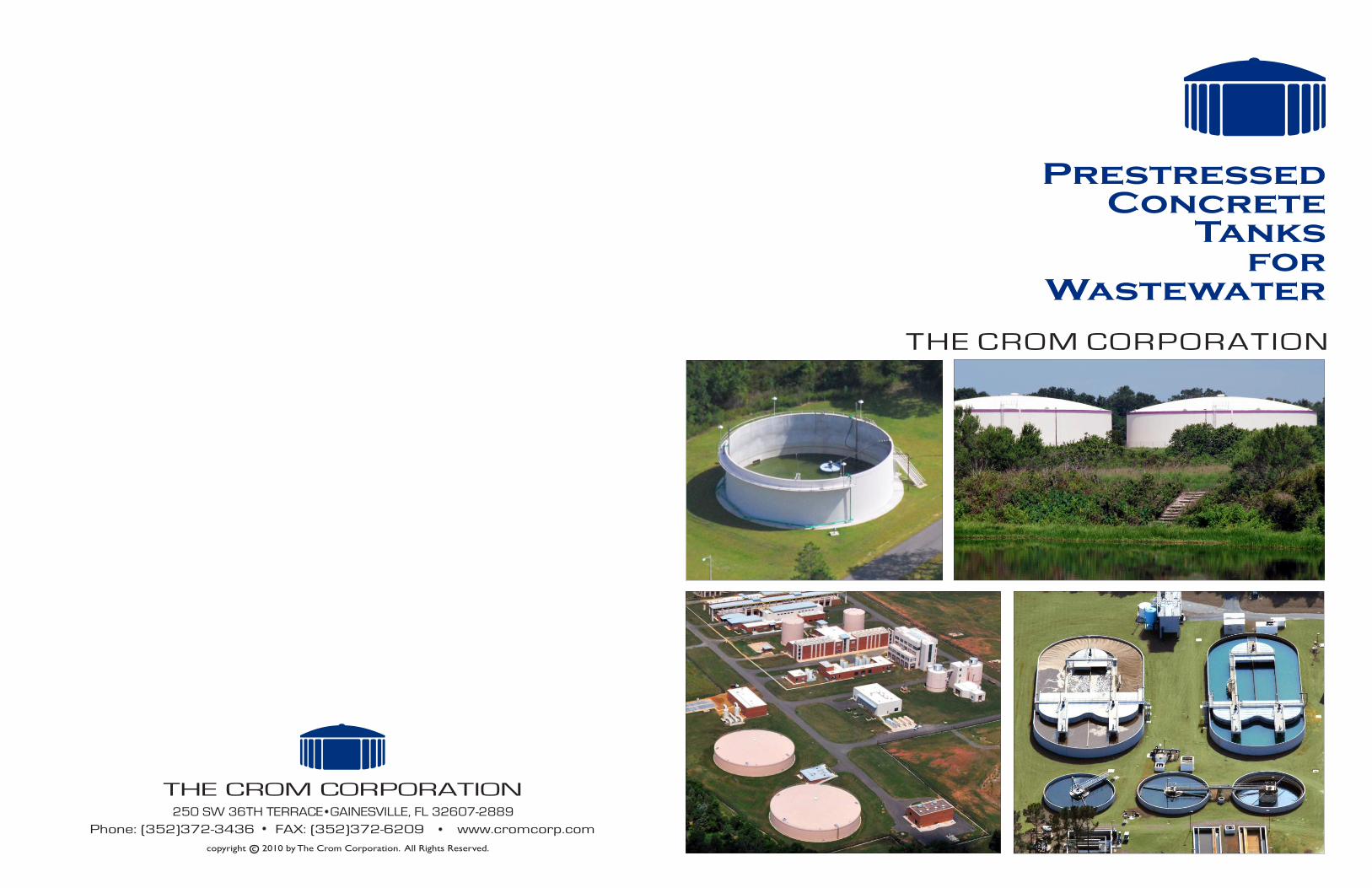
PrestressedConcrete
Tanksfor
Wastewater
Valrico Two-5 MGReuse - reshoot
THE CROM CORPORATION

Page 1
Introduction
Cover Photos1
1
2
2
3
3
4
4
Hillsborough County - Valrico AWTPDover, FloridaTwo 5,000,000-Gallon Reuse Tanks155’ x 35’6” with domesConsulting Engineers:Malcolm Pirnie, Inc.
Gulf Coast Electric Cooperative, Inc.Southport, Florida800,000-Gallon Aerobic Digester77’ x 23’Consulting Engineers:Preble-Rish, Inc.
Valrico Two-5 MGReuse - reshoot
Clay County Utility AuthorityMiddleburg, FloridaElongated Oxidation TanksTwo 2,000,000-Gallon (Single Train)(built in 1995 & 2007)212’ long x 96’4” wide x 15’ highTwo 360,000-Gallon Clarifiers (built in 1995)& One 360,000-Gallon Clarifier (built in 2007)60’ x 17’2” (each)Consulting Engineers:Mittauer & Associates, Inc.
Loudoun County Sanitation AuthorityAshburn, VirginiaTwo 5,000,000-Gallon Equalization Tanks185’ x 25’9” with domes Two 1,800,000-Gallon Permeate Tanks65’ x 70’3” with domesTwo 600,000-Gallon Anaerobic Digesters50’ x 63’11” with concrete cone roofs and floorsConsulting Engineers:CH2M Hill
Throughout the 1940s and early 1950s, J. M. Crom, Sr. was instrumental in developing the concept of building the prestressed composite wall system. This wall system consists of an impermeable steel shell diaphragm, shotcrete encasement, and single-wire circumferential prestressing.
The CROM Corporation was founded in1953. The prime purpose of the Company was to perfect the design and construction techniques for water and wastewater tanks utilizing the composite wall system. In 1954, the Company built its first open-top wastewater tank. Over the years the composite wall with a concrete floor has proven to be a very durable, low-maintenance structure able to tolerate the aggressive wastewater environment making it an ideal application for wastewater tanks. Today, the Company’s primary goal is to provide a turnkey design and construction service by building guaranteed watertight tanks stressing the highest structural integrity, long-term performance and economy. The CROM Corporation has designed and constructed in its own name and with its own forces over 3,800 circular and elongated Prestressed Concrete Tanks for water and wastewater storage and treatment using the prestressed composite wall system.
Prestressed Concrete Tanks using
CROM PRESTRESSED CONCRETE TANKS….are the preferred structures for wastewater treatment plants….because the cost of initial construction and the cost of future maintenance are both subjects of major concern in wastewater treatment plants.…and the selection of CROM tanks alleviates those concerns. Utility managers and their consulting engineers have been specifying CROM Prestressed Concrete Tanks since the early 1950s, enjoying economy of initial construction and minimizing the cost and the difficulties associated with shutting down a wastewater plant for maintenance or repairs. Here are other reasons why The CROM Corporation's tanks have been so successful:
Crom PrestressedConcrete Tanks
Page 2
Our experienced area managers, project managers, and estimators are available for consultation early during project development and, upon request, will provide preliminary drawings and accurate cost estimates of the tank portions of the project. This service is offered to our clients at no cost.
Close coordination with our clients leads to accurate engineering decisions regarding tank dimensions, required sumps, piping penetrations, launders, and accommodations for equipment. Our own Registered Professional Engineers are specialists in the design and construction of water-holding vessels and are a valuable source of assistance during project development. This results in a well-coordinated tank project all the way from design to completion of construction.
Our field superintendents and other key personnel are well versed in the construction of wastewater tanks and recognize the importance of ATTENTION TO DETAIL required for the accommodation of equipment in many of these tanks.
All CROM tanks carry a five-year guarantee for water-tightness and structural integrity.
The Company is held in very high regard in the water and wastewater industry.
Page 3
Crom Tanksin ServiceVintage
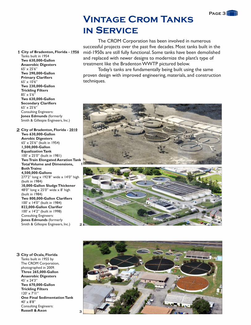
City of Ocala, Florida
Three 265,000-GallonAnaerobic Digesters45’ x 24’3”Two 670,000-GallonTrickling Filters120’ x 7’11”One Final Sedimentation Tank40’ x 8’8”Consulting Engineers:Russell & Axon
Tanks built in 1955 byThe CROM Corporation,photographed in 2009.
Two 630,000-GallonAnaerobic Digesters65’ x 25’6”
Two 230,000-GallonTrickling Filters85’ x 5’6”
Consulting Engineers:Jones Edmunds (formerlySmith & Gillespie Engineers, Inc.)
Tanks built in 1954
Two 290,000-GallonPrimary Clarifiers65’ x 10’6”
Two 630,000-GallonSecondary Clarifiers65’ x 25’6”
Two 630,000-GallonAerobic Digesters65’ x 25’6” (1,500,000-GallonEqualization Tank100’ x 25’0” Two Train Elongated Aeration TankTotal Volume and Dimensions, Both Trains:
Consulting Engineers:
built in 1954)
(built in 1981)
4,500,000-Gallons277’2” long x 192’8” wide x 14’0” high(built in 1984)30,000-Gallon Sludge Thickener48’0” long x 25’0” wide x 8’ high(built in 1984)Two 800,000-Gallon Clarifiers100’ x 14’0” (built in 1984)822,000-Gallon Clarifier100’ x 14’2” (built in 1998)
Jones Edmunds (formerlySmith & Gillespie Engineers, Inc.)
City of Bradenton, Florida - 1956
City of Bradenton, Florida - 2010
The CROM Corporation has been involved in numerous successful projects over the past five decades. Most tanks built in the mid-1950s are still fully functional. Some tanks have been demolished and replaced with newer designs to modernize the plant’s type of treatment like the Bradenton WWTP pictured below.
Today’s tanks are fundamentally being built using the same proven design with improved engineering, materials, and construction techniques.
1
1
2
2
3
3
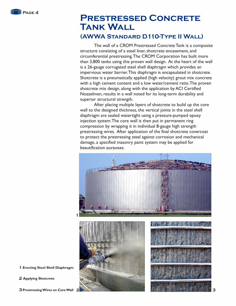
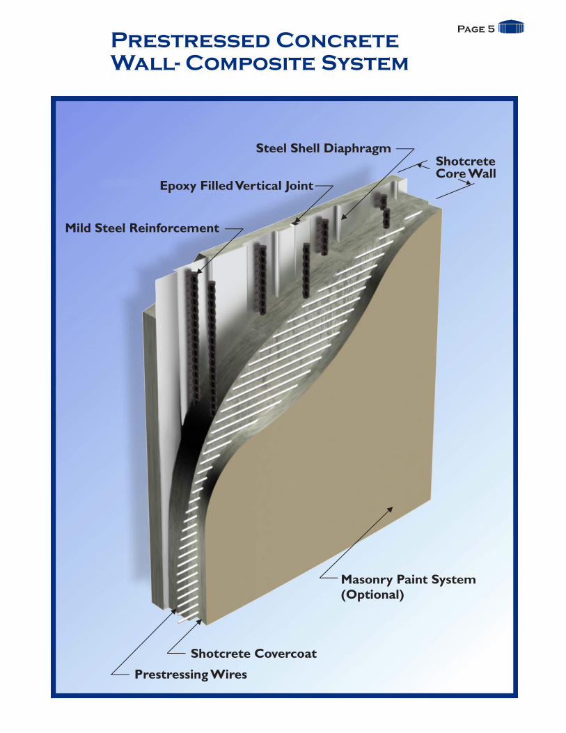
The wall of a CROM Prestressed Concrete Tank is a composite structure consisting of a steel liner, shotcrete encasement, and circumferential prestressing. The CROM Corporation has built more than 3,800 tanks using this proven wall design. At the heart of the wall is a 26-gauge corrugated steel shell diaphragm which provides an impervious water barrier. This diaphragm is encapsulated in shotcrete. Shotcrete is a pneumatically applied (high velocity) grout mix concrete with a high cement content and a low water/cement ratio. The proven shotcrete mix design, along with the application by ACI Certified Nozzelmen, results in a wall noted for its long-term durability and superior structural strength.
After placing multiple layers of shotcrete to build up the core wall to the designed thickness, the vertical joints in the steel shell diaphragm are sealed watertight using a pressure-pumped epoxy injection system. The core wall is then put in permanent ring compression by wrapping it in individual 8-gauge high strength prestressing wires. After application of the final shotcrete covercoat to protect the prestressing steel against corrosion and mechanical damage, a specified masonry paint system may be applied for beautification purposes.
Prestressed ConcreteTank Wall
Page 4
(AWWA Standard D110-Type II Wall)
1
1
2
23 3Prestressing Wires on Core Wall
Erecting Steel Shell Diaphragm
Applying Shotcrete
Page 5
Prestressed ConcreteWall- Composite System
Shotcrete Covercoat
Masonry Paint System(Optional)
Prestressing Wires
Steel Shell DiaphragmShotcreteCore Wall
Epoxy Filled Vertical Joint
Mild Steel Reinforcement

During early stages of project development, The CROM Corporation works closely with the owner's consulting engineer to develop good construction details that will be agreeable to all parties participating in the project. We are acutely aware of the fact that clear coordination must go into each clarifier project, from the original cost estimate through to the finished tank. In addition to tank dimensions, areas of particular attention include the floor slope, sumps, launders, pipe penetrations, equipment anchorages, and bridge supports.
Upon award of the contract, our engineering group will work effectively with the consulting engineer and equipment supplier to generate an accurate and detailed set of working drawings for the clarifier tank prior to construction. Our project managers and construction superintendents understand the serious nature of clarifier construction and the importance of giving ATTENTION TO DETAIL when working to build a trouble-free operational clarifier.
ClarifiersPage 6
City of Marianna, FloridaTwo 1,000,000-GallonFinal Clarifiers90’ x 16’2”Consulting Engineers:Hatch Mott MacDonald
City of Summerville, GeorgiaTwo 500,000-Gallon Clarifiers75’ x 16’2”Consulting Engineers:Ladd EnvironmentalConsultants, Inc.
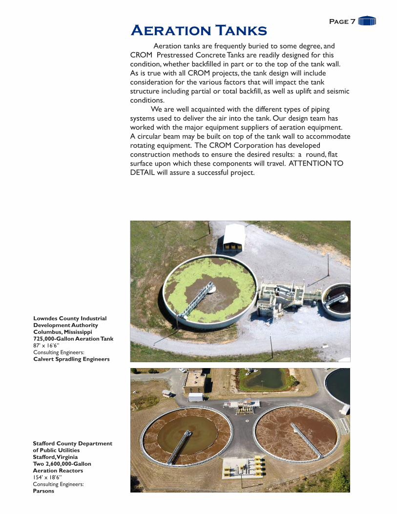
Aeration tanks are frequently buried to some degree, and CROM Prestressed Concrete Tanks are readily designed for this condition, whether backfilled in part or to the top of the tank wall. As is true with all CROM projects, the tank design will include consideration for the various factors that will impact the tank structure including partial or total backfill, as well as uplift and seismic conditions. We are well acquainted with the different types of piping systems used to deliver the air into the tank. Our design team has worked with the major equipment suppliers of aeration equipment. A circular beam may be built on top of the tank wall to accommodate rotating equipment. The CROM Corporation has developed construction methods to ensure the desired results: a round, flat surface upon which these components will travel. ATTENTION TO DETAIL will assure a successful project.
Aeration TanksPage 7
Lowndes County IndustrialDevelopment AuthorityColumbus, Mississippi725,000-Gallon Aeration Tank87’ x 16’6”Consulting Engineers:Calvert Spradling Engineers
Stafford County Departmentof Public UtilitiesStafford, VirginiaTwo 2,600,000-GallonAeration Reactors154’ x 18’6”Consulting Engineers:Parsons
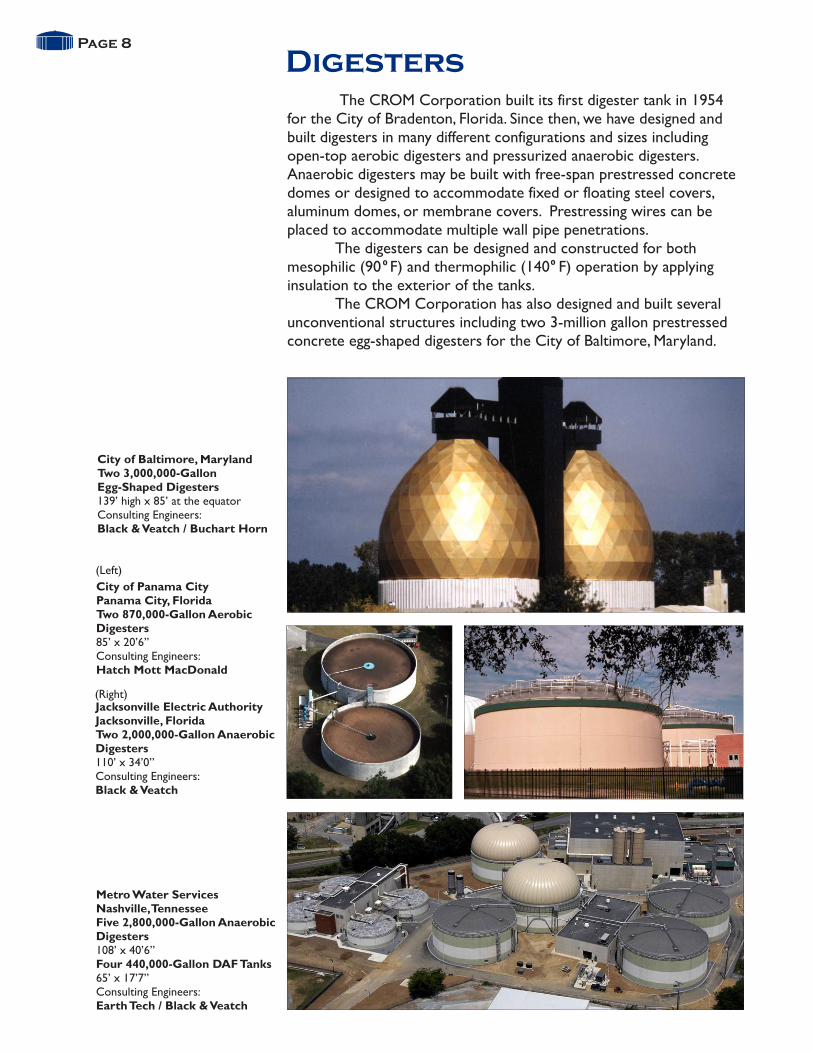
The CROM Corporation built its first digester tank in 1954 for the City of Bradenton, Florida. Since then, we have designed and built digesters in many different configurations and sizes including open-top aerobic digesters and pressurized anaerobic digesters. Anaerobic digesters may be built with free-span prestressed concrete domes or designed to accommodate fixed or floating steel covers, aluminum domes, or membrane covers. Prestressing wires can be placed to accommodate multiple wall pipe penetrations.
The digesters can be designed and constructed for both mesophilic (90 F) and thermophilic (140 F) operation by applying insulation to the exterior of the tanks.
The CROM Corporation has also designed and built several unconventional structures including two 3-million gallon prestressed concrete egg-shaped digesters for the City of Baltimore, Maryland.
DigestersPage 8
Metro Water ServicesNashville, TennesseeFive 2,800,000-Gallon AnaerobicDigesters108’ x 40’6”Four 440,000-Gallon DAF Tanks65’ x 17’7”Consulting Engineers:Earth Tech / Black & Veatch
City of Baltimore, MarylandTwo 3,000,000-GallonEgg-Shaped Digesters139’ high x 85’ at the equatorConsulting Engineers:Black & Veatch / Buchart Horn
City of Panama CityPanama City, FloridaTwo 870,000-Gallon AerobicDigesters85’ x 20’6”Consulting Engineers:Hatch Mott MacDonald
(Left)
(Right)
central nashville
Jacksonville Electric AuthorityJacksonville, FloridaTwo 2,000,000-Gallon AnaerobicDigesters110’ x 34’0”Consulting Engineers:Black & Veatch
0 0

Modified Egg-ShapedDigesters
Page 9
Western Carolina RegionalSewer AuthorityGreenville, South CarolinaTwo 850,000-GallonAnaerobic Digesters50’ x 56’2” with conical roofsConsulting Engineers:Camp Dresser & McKee, Inc.
Loudoun County SanitationAuthorityAshburn, VirginiaTwo 600,000-Gallon AnaerobicDigesters50’ x 63’11”with steeply slopedconical floors and conical roofsConsulting Engineers:CH2M Hill
The design and unique construction methods used by The CROM Corporation are well suited for building Modified Egg-Shaped Digesters. These structures typically incorporate a small tank diameter and tall sidewall heights, along with a steeply sloped hopper floor. This type of digester minimizes dead zones at the floor/wall and roof/wall intersections thus reducing sludge buildup and downtime for clean-out maintenance. These digesters are a viable alternative to other types of digesters, especially when considering life-cycle costs.
The CROM Corporation utilizes a unique formwork system to construct the steeply sloped, cone-shaped hopper floors. This self-supporting, tie-less concrete casting system was designed to enable low concrete drops while being accessible for vibrating, ensuring excellent concrete consolidation and a smooth interior finish of the hopper.
The balance of the digester is constructed using our composite wall system. The free-span concrete dome or conical concrete roof is designed to accommodate internal operating pressures and to support specified rooftop equipment.

In the mid-1980s, The CROM Corporation developed unique design and construction methods for building Elongated Prestressed Concrete Tanks. These tanks feature our steel shell/shotcrete composite walls, together with linear and circumferential prestressing. This innovative design has produced tanks with outstanding qualities: durability, watertightness, structural integrity, attractive appearance and long-range economy.
The CROM Corporation has extensive experience working with all major equipment suppliers. We work with the consulting engineer and equipment suppliers early in the project to ensure that all design parameters are met and details are finalized before construction starts.
Page 10
Elongated PrestressedConcrete Tanks
City of Plant CityPlant City, FloridaThree Train ElongatedAeration TankVolume and Dimensions,Total Three Trains:14,100,000 Gallons 262’ long x 351’ wide x 22’6” highThree 1,500,000-Gallon Clarifiers130’ x 15’11”Consulting Engineers:Malcolm Pirnie, Inc.
Town of Callahan, FloridaElongated Oxidation Tank820,000-Gallon (Single Train)206’3” long x 40’6” wide x13’9” highTwo 110,000-Gallon Clarifiers35’ x 15’8”Consulting Engineers:Mittauer & Associates, Inc.
City of Groveland, FloridaTwo Train Elongated Aeration TankVolume and Dimensions,Total Both Trains:965,000 Gallons154’ long x 80’6” wide x 12’8” highTwo 278,000-Gallon Clarifiers55’ x 15’8”Consulting Engineers:Metzger & Willard, Inc.

The CROM Corporation is well acquainted with the design and construction of SBR tanks. Close coordination with the consulting engineer and the SBR manufacturer ensures the proper accommodation of equipment components.
An exterior concrete walkway can be built as an integral part of the tank wall. Engineers often locate the circumferential walkway three to four feet below the top of the wall, thus eliminating the need for an interior aluminum handrail.
Sequencing BatchReactor (SBR) Tanks
Page 11
Gulf Coast Electric Cooperative, Inc.Southport, FloridaTwo 1,000,000-Gallon SBR Tankswith exterior walkways90’ x 23’Consulting Engineers:Preble-Rish, Inc.
City of Belleview, FloridaTwo 600,000-Gallon SBR Tanks72’ x 21’Consulting Engineers:Barnes, Ferland andAssociates Inc.
Town of Braselton, GeorgiaTwo 1,200,000-Gallon SBR Tankswith exterior walkways92’1” x 24’Consulting Engineers:Engineering Management Inc.
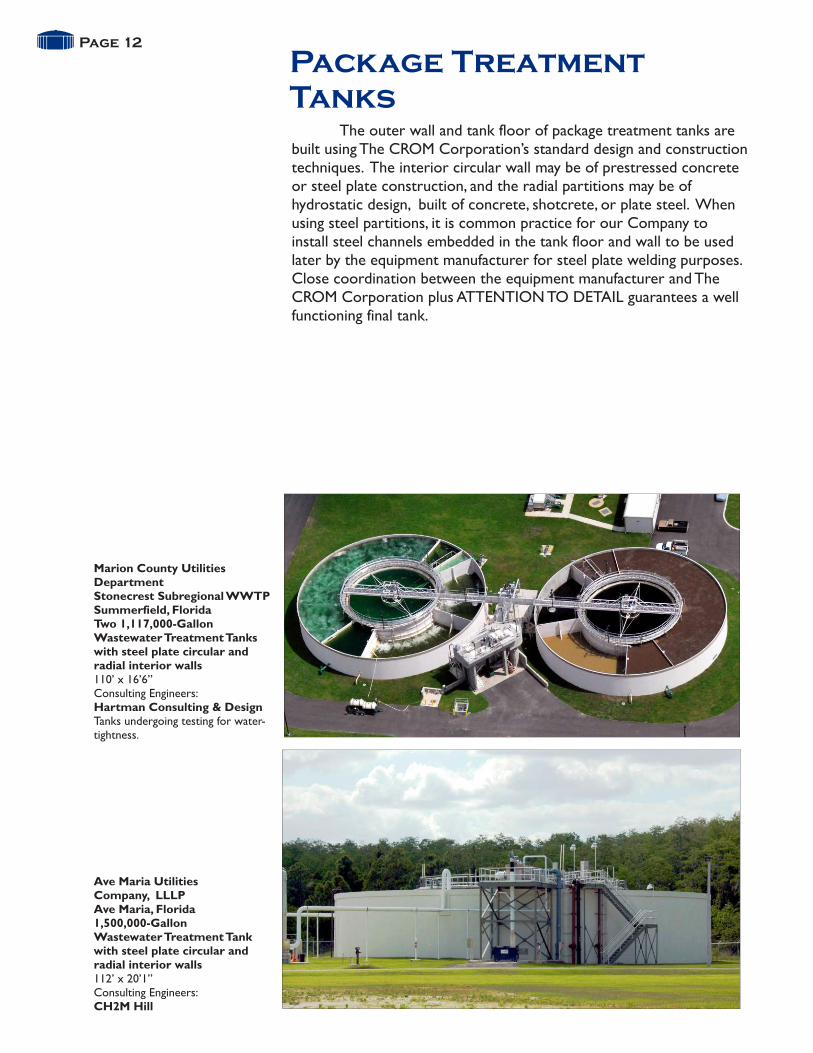
The outer wall and tank floor of package treatment tanks are built using The CROM Corporation’s standard design and construction techniques. The interior circular wall may be of prestressed concrete or steel plate construction, and the radial partitions may be of hydrostatic design, built of concrete, shotcrete, or plate steel. When using steel partitions, it is common practice for our Company to install steel channels embedded in the tank floor and wall to be used later by the equipment manufacturer for steel plate welding purposes. Close coordination between the equipment manufacturer and The CROM Corporation plus ATTENTION TO DETAIL guarantees a well functioning final tank.
Package TreatmentTanks
Page 12
Marion County UtilitiesDepartmentStonecrest Subregional WWTPSummerfield, FloridaTwo 1,117,000-GallonWastewater Treatment Tanks
110’ x 16’6”Consulting Engineers:Hartman Consulting & DesignTanks undergoing testing for water- tightness.
with steel plate circular andradial interior walls
Ave Maria UtilitiesCompany, LLLPAve Maria, Florida1,500,000-GallonWastewater Treatment Tankwith steel plate circular andradial interior walls112’ x 20’1”Consulting Engineers:CH2M Hill
Stonecrest - 07078Need Photos

The storage of treated wastewater for reuse is an excellent application for CROM Prestressed Concrete Tanks. These tanks can be located at the treatment plant facility or at points of use, such as golf courses or agricultural lands, where the water is used for irrigation purposes. CROM Prestressed Concrete Tanks can readily be embellished with architectural treatment or can be fully or partially buried.
Page 13
Reuse WaterStorage Tanks
Florida Keys AqueductAuthority - Duck Key, Florida200,000-Gallon ReclaimedWater Storage Tank35’ x 27’9” with domeConsulting Engineers:Mathews Consulting, Inc.
On Top of the WorldClearwater, Florida2,000,000-Gallon ReuseWater Storage Tank120’ x 28’6” with domeConsulting Engineers:Jones, Edmunds
City of Tallahassee, Florida500,000-Gallon Reuse WaterStorage Tank60’ x 23’8” with domeConsulting Engineers:Camp Dresser & McKee, Inc.
City of Boca Raton, Florida5,000,000-Gallon ReclaimedWater Storage Tank witharchitectural treatment155’ x 35’6” with domeConsulting Engineers:Mathews Consulting, Inc.
Page 14
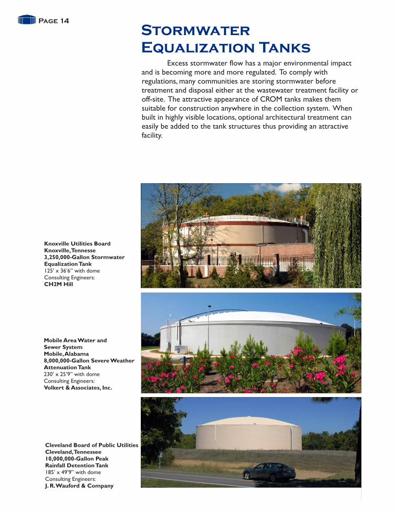
Stormwater Equalization Tanks
Mobile Area Water andSewer SystemMobile, Alabama8,000,000-Gallon Severe WeatherAttenuation Tank230’ x 25’9” with domeConsulting Engineers:Volkert & Associates, Inc.
Knoxville Utilities BoardKnoxville, Tennesse3,250,000-Gallon StormwaterEqualization Tank125’ x 36’6” with domeConsulting Engineers:CH2M Hill
Excess stormwater flow has a major environmental impact and is becoming more and more regulated. To comply with regulations, many communities are storing stormwater before treatment and disposal either at the wastewater treatment facility or off-site. The attractive appearance of CROM tanks makes them suitable for construction anywhere in the collection system. When built in highly visible locations, optional architectural treatment can easily be added to the tank structures thus providing an attractive facility.
Cleveland Board of Public UtilitiesCleveland, Tennessee10,000,000-Gallon PeakRainfall Detention Tank185’ x 49’9” with domeConsulting Engineers:J. R. Wauford & Company
Page 15
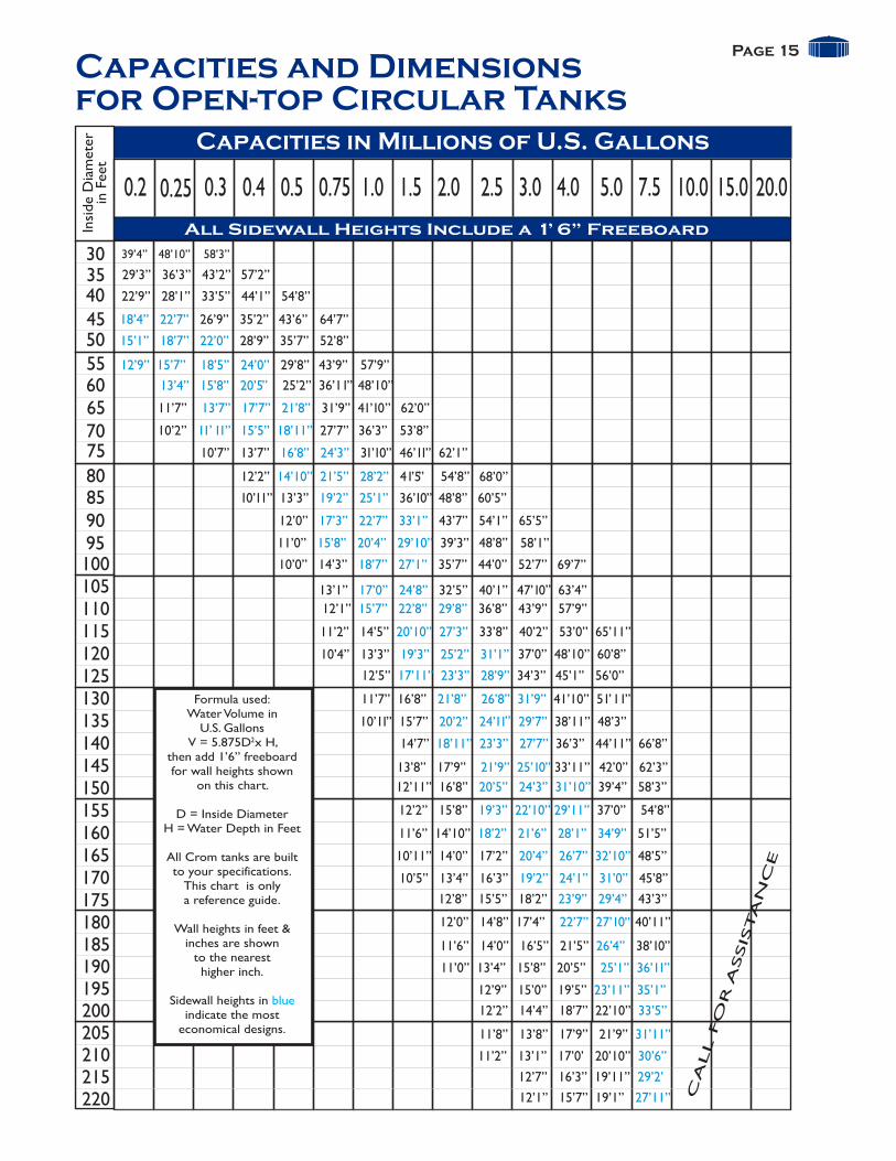
Capacities in Millions of U.S. Gallons
0.2 0.3 0.4 0.5 0.75 1.0 1.5 2.0 2.5 3.0 4.0 5.0 7.5 10.0 15.0 20.0 0.25
Capacities and Dimensionsfor Open-top Circular Tanks
Insi
de
Dia
met
erin
Fee
t
30354045505560657075
80859095100105110115120125130135140145150155160165170175180185190195200205210215220
39’4” 48’10” 58’3”
29’3” 36’3” 43’2” 57’2”
22’9” 28’1” 33’5” 44’1” 54’8”
18’4” 26’9” 35’2” 43’6” 64’7”22’7”
15’1” 18’7” 22’0” 28’9” 35’7” 52’8”
12’9” 15’7” 18’5” 24’0” 29’8” 43’9” 57’9”
13’4” 15’8” 20’5” 25’2” 36’11” 48’10”
11’7” 31’9” 41’10” 62’0”13’7” 17’7” 21’8”
10’2” 27’7” 36’3” 53’8” 11’ 11” 15’5” 18’11”
10’7” 13’7” 31’10” 46’11” 62’1”16’8” 24’3”
12’2” 41’5” 54’8” 68’0”14’10” 21’5” 28’2”
10’11” 13’3” 36’10” 48’8” 60’5” 19’2” 25’1”
12’0” 43’7” 54’1” 65’5”17’3” 22’7” 33’1”
11’0” 39’3” 48’8” 58’1”15’8” 20’4” 29’10”
10’0” 14’3” 35’7” 44’0” 52’7” 69’7”18’7” 27’1”
13’1” 32’5” 40’1” 47’10” 63’4”17’0” 24’8”
12’1” 36’8” 43’9” 57’9” 15’7” 22’8” 29’8”
11’2” 14’5” 33’8” 40’2” 53’0” 65’11”20’10” 27’3”
10’4” 13’3” 37’0” 48’10” 60’8”19’3” 25’2” 31’1”
12’5” 34’3” 45’1” 56’0” 17’11” 23’3” 28’9”
11’7” 16’8” 41’10” 51’11”21’8” 26’8” 31’9”
10’11” 15’7” 38’11” 48’3” ”20’2’’ 24’11 29’7”
14’7” 36’3” 44’11” 66’8”18’11” 23’3” 27’7”
13’8” 17’9” 33’11” 42’0” 62’3” 21’9” 25’10”
12’11” 16’8” 39’4” 58’3” 20’5” 24’3” 31’10”
12’2” 15’8” 37’0” 54’8”19’3” 22’10” 29’11”
11’6” 14’10” 51’5” 18’2” 21’6” 28’1” 34’9”
10’5” 13’4” 16’3” 45’8” 19’2” 24’1” 31’0”
10’11” 14’0” 17’2” 48’5” 20’4” 26’7” 32’10”
12’8” 15’5” 18’2” 43’3” 23’9” 29’4”
12’0” 14’8” 17’4” 40’11” 22’7” 27’10”
11’6” 14’0” 16’5” 21’5” 38’10” 26’4”
11’0” 13’4” 15’8” 20’5” 25’1” 36’11”
12’9” 15’0” 19’5” 23’11” 35’1”
12’2” 14’4” 18’7” 22’10” 33’5”
11’8” 13’8” 17’9” 21’9” 31’11”
11’2” 13’1” 17’0’ 20’10” 30’6”
12’7” 16’3” 19’11” 29’2’
12’1” 15’7” 19’1” 27’11” CA
LL F
OR
ASSIS
TA
NC
E
Formula used:Water Volume in
U.S. Gallons V = 5.875D x H,
then add 1’6” freeboardfor wall heights shown
on this chart.
D = Inside DiameterH = Water Depth in Feet
All Crom tanks are builtto your specifications.
This chart is onlya reference guide.
Wall heights in feet &inches are shown
to the nearesthigher inch.
Sidewall heights in indicate the most
economical designs.
blue
2
All Sidewall Heights Include a 1’ 6” Freeboard

Page 16
Longevity
Tanks Built in 1973-1,250,000-Gallon PotableWater Storage Tank90’ x 26’3” with domeTwo 400,000-Gallon Softeners65’ x 16’6”58,000-Gallon SludgeThickener30’ x 11’Consulting Engineers:Russell & Axon, Inc.
Tanks Built in 1986-1,250,000-Gallon PotableWater Storage Tank90’ x 26’3” with dome800,000-Gallon Softener88’ x 17’9”58,000-Gallon SludgeThickener30’ x 11’Consulting Engineers:Russell & Axon, Inc.
Tank Built in 1991-5,000,000-Gallon ReuseWater Storage Tank145’ x 41’ with domeConsulting Engineers:McKim & Creed, PA(formerly Briley, Wild& Associates)
Tank Built in 2006-2,500,000-Gallon PotableWater Storage Tank128’ x 26’3” with domeConsulting Engineers:Malcolm Pirnie, Inc.
Tank Built in 1997-Elongated 5-StagePrestressed ConcreteTreatment Basin(Two Trains)538’8” long x 243’ wide x17’9” wall heightConsulting Engineers:McKim & Creed, PA
Tanks Built in 1999-Three 600,000-Gallon Clarifiers85’ x 16’2”Consulting Engineers:McKim & Creed, PA
City of Daytona Beach, Florida
THE CROM CORPORATION SUPPORTS:
Through the years, The CROM Corporation has built water and wastewater tanks for the City of Daytona Beach, Florida. All the tanks are as serviceable today as they were when they were built. The photograph below was taken in 2010.
Ralph Brennan Water Treatment Plant Westside Regional Wastewater Treatment Plant
AWWA