pressure swing absorption device and process for ... library/research/coal/carbon capture... ·...
TRANSCRIPT

Pressure Swing Absorption Device and Process for Separating CO2 from Shifted Syngas and its
Capture for Subsequent Storage
John Chau, Jie Xingming, Gordana Obuskovic,and
Kamalesh K. Sirkar
Otto H. York Department of Chemical, Biological and Pharmaceutical Engineering
New Jersey Institute of TechnologyNewark, NJ 07102
DOE-NETL Award No. DE-FE00013232011 NETL CO2 Capture Technology Meeting, Pittsburgh, PA , August 26, 2011

• Technology Description(a) Process and Device Concept(b) Detailed Considerations on Process and
Device• Project Objectives• Phase II Progress• Project Structure• Project Budget• Project Management Plan including Risk
Management

Pressure swing absorption of CO2 for post low-temperature shift reactor gas using membrane contactors containing ionic liquids, dendrimers etc.

Concentration profile for absorbed species in gas and liquid phases in a membrane
contactorro
ri
Cjg
GAS
PG
CjlPAb
ABSORBENTLIQUID
FIBER WALL
PAb PG>

Schematic of the absorber containing ceramic tubules or hollow fibers
GASINLET
CLOSEDEND
LIQUIDINLET
GASOUTLET
POTTED TUBESHEET
TUBULE OR HOLLOW FIBER

Pressure Swing Absorption Operation
Solenoid Valve Locations in Pressure Swing Absorption
(PSAB) Apparatus
Pressure vs. time profile in the bore of tubule or hollow
fiber in PSAB
(Bhaumik et al., AIChE J., 42, 409-421 (1996))

Pressure Swing Absorption (PSAB) in a Membrane Contactor Device
• Basic separation concept implemented with 10% CO2-90% N2 gas mixture at 375 kPa and 19.5 wt% aqueous DEA solution (RAPSAB –Rapid Pressure Swing Absorption)
• Its adaptation to the current problem of treating low temperature post-shift reactor synthesis gas at ~20 atm and 150-1800C
Potential Advantages of the Proposed Separation Technique-1
• Has high solubility selectivity of novel selected liquid absorbents having relatively high viscosity
• Has high purification ability of pressure swing adsorption process
• Has high gas-liquid contacting surface area per unit device volume
• Has a compact membrane-like device• Scale up should be easier due to modularity of
membrane-based devices and membrane-based phase contacting
Potential Advantages of the Proposed Separation Technique-2
• Will deliver highly purified H2 at nearly its partial pressure and temperature in the post-shifted reactor synthesis gas feed
• Purified CO2 stream will be available at ~1atm

• Technology Description(a) Process and Device Concept(b) Detailed Considerations on Process and
Device• Project Objectives• Phase II Progress• Project Structure• Project Budget• Project Management Plan including Risk
Management

Nonvolatile Absorbents for PSAB
1. Ionic Liquids:[bmim]+[PF6]
- (Fluka)[bmim]+[DCA]- (Merck)[Am-Im]+[DCA]- (Functionalized)
(with or without moisture)
General structures of (a) imidazolium-based RTILs, (b) [C2mim][X] RTILs, and (c) [Rmim][Tf2N] RTILs. (Bara et al., Ind. Eng. Chem. Res., 48, 2739 (2009))
N N+
CnH2n+1
CnH2n
NH2
(CN)2- N
(d)
(d) Functionalized IL structure for [Am-Im]+[DCA]-

Nonvolatile Absorbents for PSAB2.(a) Dendrimers/hyperbranched polymers of lower molecular weight:
Polyamidoamine (PAMAM) generation 0, MW-516, 4 primary amines, 2 tertiary amines;
Generation 2, MW-3130(Dendritech, Midland, MI)Use in a nonvolatile solvent, such as polyethylene glycol (PEG 400)Highly reactive in the presence of moisture
(1. Kovvali et al., JACS, 122 (31) 7594 (2000); 2. Kovvali and Sirkar, I&E C Res., 40(11), 2502 (2001); 3. Kosaraju et al., I&E C Res., 49, 1250 (2005))
(b) Polyethyleneimines of lower molecular weight, Lupasol FG (BASF), MW-615 (Rolker et al., I&E C Res., 46, 6572 (2007)
(a) PAMAM dendrimer of generation 0

Adaptation of PSAB Device to the Current Problem
1. Porous PP membrane substrate replaced by hydrophobized porous ceramic tubules, porous PTFE hollow fibers and hydrophobized PEEK hollow fibers (higher temperature, wettability considerations)
2. High pressure means smaller membrane pore size (5 nm to 10 nm) at the gas-liquid interface to prevent any phase breakthrough
3. Longer length of hollow fibers in RAPSAB replaced by number of modules of hollow fiber/ceramic tubules in series (limitation of oven dimensions)
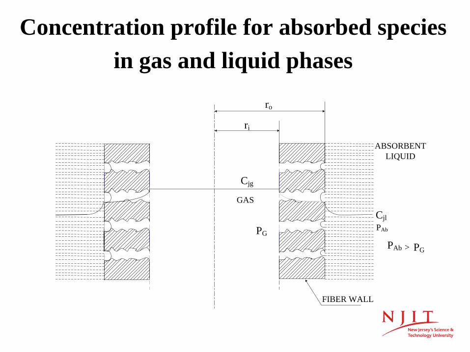
Concentration profile for absorbed species in gas and liquid phases
ro
ri
Cjg
GAS
PG
CjlPAb
ABSORBENTLIQUID
FIBER WALL
PAb PG>

Breakthrough pressure for a nonwetted pore size of radius rp
(Young-Laplace Equation)
Increase , decrease The pores should remain nonwetted.
γ
2 cosbreakthrough
p
Pr
γ θ∆ ≅
pr

Nondisperssive Gas Absorption/Stripping Requires Nonwetted Pores
1. To prevent spontaneous pore wetting
2. γcritical of fluoropolymers, C18 surfaces….15-20 dyne/cm
3. Absorbent liquids under consideration have considerably higher γ values; γ will fluctuate due to absorption and desorption of moisture
Surface tension of absorbent liquid of the polymeric coatingcriticalγ γ>

• Ceramic Tubules:1.5 mm I.D., 3.8 mm O.D. γ-alumina coating on alpha-alumina substrate hydrophobized with nonafluorohexylsilane coatingPore radius ~5 nm <0.03µm , 940 m2/m3 surface area/device volumeFor say, a 40 dyne/cm liquid to withstand 20 atm+, 10 nm pore size C18 hydrophobic coatings and epoxy-based tube sheet up to 2000C
(Media and Process Technology, Pittsburgh, PA; Rich Ciora/Paul K.T. Liu)
• Teflon Hollow Fibers:0.53 mm I.D., 1.08 mm O.D. Pore size <0.1µmPlasma polymerize a nanoporous fluorosilicone coating to reduce the pore size to ≤0.01µm
(Applied Membrane Technologies, Inc., Minnetonka, MN; Stephen Conover)
• PEEK Hollow Fibers:300 µm I.D., 500 µm O.D., porous hollow fibers of poly (ether ether ketone), hydrophobized surface via fluorination of the surfaces
(Porogen Inc., Woburn, MA; Ben Bikson)

CO2 Gas-Liquid/Liquid-Gas Mass Transfer Aspects
• Stagnant highly viscous absorbent liquid on the shell side
• Tube-side flowing gas present in pores of membrane
• High temperature of operation will reduce µabsorbentdrastically
2
2
2
1
CO
CO
COabsorbent
DRateof physical gas absorption
tD t
Amount absorbed per unit area
D
απ
απ
αµ

Gas Mixture to be Studied
• 45% He, 30% CO2, Rest being H2O• ~1500C, 200-300 psig• Helium as a surrogate for H2
• Typical Gasifier Composition:~38% H2, 29% CO2, 33% H2O, 0.15% CO

Schematic of the experimental setup for pressure swing absorption
Timer
2-WSV2-WSV
2-WSV
PG
PG
SD
MVFM
To GC
CV
FMC
CV
To GC
LPGC
RV CV
RV
PG
LST
TimerAD: Absorption deviceCV: Check valveFM: Flow meterFMC: Feed mixture cylinderGC: Gas chromatographH: HumidifierHP: Humidity probeLPGC: Liquid pressurizing gas
cylinderLST: Liquid storage tankMV: Metering valvePG: Pressure gaugeRV: Regulating valveSD: Surge drum2-WSV: 2 - way solenoid valve
AD
Liquid drain
Temperature controlled oven
HPH

1
2
3
Step 1 Feed gas introduction (valve 1)
Cycle beginning
Process of pressure swing absorption for separating CO2 from shifted syngas: 3-Valve system
Module
Feed
CO2 product
Helium Product

1
2
3
Step 1 Feed gas introduction (valve 1)
Cycle beginning
Step 2 Absorption
Process of pressure swing absorption for separating CO2 from shifted syngas: 3-Valve system
Module
Feed
CO2 product
Helium Product

1
2
3
Step 1 Feed gas introduction (valve 1)
Cycle beginning
Step 2 AbsorptionStep 3 Helium product release (valve 2)
Process of pressure swing absorption for separating CO2 from shifted syngas: 3-Valve system
Module
Feed
CO2 product
Helium Product

1
2
3
Step 1 Feed gas introduction (valve 1)
Cycle beginning
Step 2 AbsorptionStep 3 Helium product release (valve 2)Step 4 CO2 product release (valve 3)
Process of pressure swing absorption for separating CO2 from shifted syngas: 3-Valve system
Module
Feed
CO2 product
Helium Product

1
2
3
Step 1 Feed gas introduction (valve 1)
Cycle beginning
Step 2 AbsorptionStep 3 Helium product release (valve 2)Step 4 CO2 product release (valve 3)
Cycle completed
Process of pressure swing absorption for separating CO2 from shifted syngas: 3-Valve system
Module
Feed
CO2 product
Helium Product

• Technology Description (a) Process and Device Concept(b) Detailed Considerations on Process and
Device• Project Objectives• Phase I Progress• Project Structure• Project Budget• Project Management Plan including Risk
Management

Project Objectives• Develop via laboratory experiments an advanced
pressure swing absorption-based device and a cyclic process to produce purified helium (a surrogate for hydrogen) at a high pressure for IGCC-CCS plant’s combustion turbine from low temperature post-shift reactor synthesis gas and simultaneously obtain a highly purified CO2 stream containing at least 90% of the CO2 in the post-shift reactor gas stream and suitable for subsequent sequestration
• Provide data and analysis of the cyclic process and device to facilitate subsequent scale up
• Develop a detailed analysis for the process and device to allow economic evaluation for potential larger-scale use

Project Objectives: PHASE-I
I1. Develop an experimental setup for studying the PSAB process
I2. Develop novel gas-liquid absorption modules employing ceramic tubules and polymeric hollow
fibers of PTFE and PEEK
I3. Initiate preliminary studies of pressure swing absorption-based separation of a moist CO2-He gas mixture at 1500C and 200-300 psig simulating a low temperature post-shift reactor synthesis gas stream

Project Objectives: PHASE-II
II1. Study the performance of the PSAB process for selected absorbents vis-à-vis purification of the feed gas stream to obtain a high pressure purified He stream and a low pressure purified CO2 stream
II2. Develop experimental setups to measure the solubility and diffusion coefficients of CO2 and He at the appropriate ranges of temperature and pressure for selected absorbents
II3. Initiate development of a mathematical model of the PSAB device and process

Project Objectives: PHASE-IIIIII1. Generate experimental data on the solubility and
diffusion coefficient for CO2 and He for the selected absorbents
III2. Compare the results of simulation of the mathematical model with the observed purification and separation in the PSAB process and device for selected absorbents
III3. Perform simulations of the model to explore scale up of the process to facilitate evaluation of the process
III4. Determine the extent of loss/deterioration of the absorbents over extended periods of operation

• Technology Description (a) Process and Device Concept(b) Detailed Considerations on Process and
Device• Project Objectives• Phase I • Project Structure• Phase II• Project Budget• Project Management Plan including Risk
Management
Details of Membrane Modules (Phase I)
* Single ceramic tubule, ‘o’-ring seal.
Membrane module type
Details of Membrane Modules
I.D. mm
O.D. mm
Pore Size µm
No. of fibers/tubules
Length Shell
Diameter
*Ceramic membrane modules # 1,2,3,4
1.5 3.8 0.005 1 18”
1/4 “ OD 0.035”
wall thickness
Teflon hollow fiber module (epoxy potting)
0.53 1.08 ̴ 0.01 18 18”
3/8” OD .035” wall
thickness PEEK hollow fiber module
(epoxy potting) 0.25 0.45 ̴ 0.01 240 18” ¼”

Module with Teflon Hollow Fibers and 4 Modules
containing Ceramic Membrane Tubules

GC
Two way solenoid valve
Ionic liquid
Pressure gauge
Feed mixture cylinder
Regulating valve
Water reservoir
Humidity probe
Water injection pump
Packing
GC
Mass flow-meter
GC
Check valve
Gas product reservoir CO2-rich
Gas product reservoirHe-rich
Oven
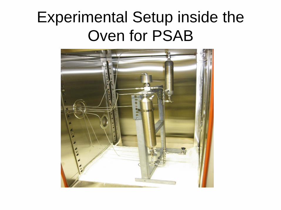
Experimental Setup inside the Oven for PSAB

GCs

PneuMagnetic PLC Control Box

PneuMagnetic PLC Control Box with Connections to the Valves inside the Oven

• Background• Technology Description (a) Process and Device Concept(b) Detailed Considerations on Process and
Device• Project Objectives• Phase I • Project Structure• Phase II• Project Budget• Project Management Plan including Risk
Management
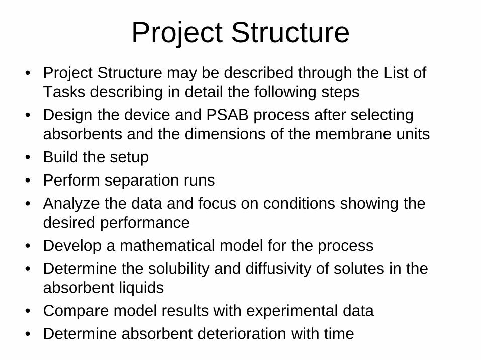
Project Structure• Project Structure may be described through the List of
Tasks describing in detail the following steps • Design the device and PSAB process after selecting
absorbents and the dimensions of the membrane units• Build the setup • Perform separation runs• Analyze the data and focus on conditions showing the
desired performance• Develop a mathematical model for the process• Determine the solubility and diffusivity of solutes in the
absorbent liquids• Compare model results with experimental data• Determine absorbent deterioration with time

Tasks to be Performed: Phase II• Task 3.0 Project Management and Planning (10/1/10 –
9/30/11) • Subtask 3.1 Provide quarterly reports at the end of every
quarter as well as a Topical Report at the end of year 2 (10/1/10 – 9/30/11)
• Task 4.0 Experimental Program and Technical Activities for Year 2 (10/1/10 – 9/30/11)
• Subtask 4.1 Study the performance of PSAB devices and the PSAB process (10/1/10 – 9/30/11)
• Subtask 4.2 Develop experimental setups to measure solubility and diffusion coefficients of CO2 and He in selected absorbent liquids (10/1/10 – 9/30/11)
• Subtask 4.3 Initiate development of a mathematical model of the PSAB device and process (10/1/10 – 9/30/11)

Liquid Breakthrough Pressure Test Results for Membrane Modules Recently Obtained (Phase II)
Room temperature, dry air sweep, liquid pressurized with nitrogen; *Epoxy-- O-ring seal
Water [Bmim][DCA][Emim][Tf2N]
PEG 40020% Dendrimer + DCA
Ceramic #7 210 psi No leakage up to 300 psi
N/A 300 psi 220 psi
Ceramic #8 No leakage up to 300 psi
No leakage up to 300 psi
180 psi No leakage up to 300 psi
N/A
PEEK #20Epoxy
No leakage up to 200 psi
40 psi N/A 140 psi N/A
PEEK #21Epoxy
No leakage up to 200 psi
No leakage up to 140 psi
N/A 180 psi N/A
2” PEEK(2PG295)
No leakage up to 200 psi
No leakage up to 200 psi
No leakage up to 200 psi
No leakage up to 200 psi
N/A
Teflon*(S/N: 1004)
No leakage up to 100 psi
100 psi N/A 80 psi 100 psi
Teflon*(S/N: 1005)
140 psi 40 psi N/A 80 psi 40 psi
Teflon*(S/N: 1006)
No leakage up to 140 psi
60 psi N/A 80 psi 60 psi

Larger Module containing PEEK Hollow Fibers in the Setup

1
2
3
Step 1 Feed gas introduction (valve 1)
Cycle beginning
Step 2 AbsorptionStep 3 Helium product release (valve 2)Step 4 CO2 product release (valve 3)
Cycle completed
Process of pressure swing absorption for separating CO2 from shifted syngas: 3-Valve system
Module
Feed
CO2 product
Helium Product

High Pressure High Temperature PSAB Test Results of Ceramic Membrane Module with a Single Tubule (N-Valve System)

High Pressure PSAB Runs with Longer PEEK Membrane Module (N-Valve System) (~25oC and 100oC)

A Few General Conclusions
• The N-valve cycle performs much better than the 3-valve cycle especially regarding the quality of the CO2 product
• Higher membrane surface area per unit device (gas) volume leads to better separation performance
• Two hollow fiber membrane modules in series deliver higher purity in both product streams compared to one
• Minor difference in performance between humidified feed gas and dry feed gas for pure [bmim][DCA] (at this time!)
• Increase in temperature reduces the performance a bit as we go up to 1000C
• Hydrophobized PEEK membrane modules yield best results

PSAB performance comparison between 3-valve and N-valve systems
using a PEEK membrane module

Physical dimensional comparison between different membrane modules

PSAB performance comparison between different membrane modules
2 PEEK MODULES IN SERIES
1 PEEK MODULE

1 - TEFLON MODULE
1 - CERAMIC MODULE

High Temperature Test Results of One PEEK Membrane Module

Solubility Measurement Schematicvacuum
Pressure Gauge 1
Pressure Gauge 2
Valve1
Valve 2
Valve 3
Gas Cylinder
Reference (CO2)Cell (ILs)
The solubility measurement system contains a cell volume, a reference volume, an oven, and gas cylinders. The procedure for measuring solubility of a desired gas is described below:
•Fill the cell volume (Vcell) with known volumes of ILs (VIL)•The system was vacuumed for at least 12 hrs with all valves open• Close valves 1 and 3•Load carbon dioxide gas (or desired gas) into the reference volume (Vref) to a desired pressure.•Close valve 2•Allow the temperature of the gas to reach desired temperature in reference volume.•Open valve 3 to allow gas to contact ILs•Allow pressure to reach equilibrium (pressure no long changed) •Final pressure difference was used to calculate the number of moles of gas absorbed by ILs

Solubility Measurement Setup

Model Equations Considering Pressure Drop in Fiber Lumen
• When gas pressure in the fiber lumen is not negligible, the governing balance equations and boundary conditions for any species j (N2, CO2) in the gas and liquid phases are shown on the next slide:
• µg is the gas mixture viscosity• Djg, Djl: Diffusion coefficient of species j in gas and liquid phase• Kjg: overall mass transfer coefficient of species j in gas phase• di, d0: inner and outer diameter of the fiber• Hj: Henry law constant of species j• re: Happel’s radius

Model Equations Considering Pressure Drop in Fiber Lumen (Cont’d)

Tasks to be Performed: Phase III• Task 5.0 Project Management and Planning (10/1/11 –
9/30/12) • Subtask 5.1 Provide quarterly reports at the end of every
quarter as well as the final Project Report at the end of year 3 (10/1/11 – 12/31/12)
• Task 6.0 Experimental Program and Technical Activities for Year 3 (10/1/11-9/30/12)
• Subtask 6.1 Determine the solubility and diffusivity of CO2and He in selected absorbents (10/1/11-6/30/12)
• Subtask 6.2 Compare mathematical model simulation results with experimental data from PSAB process (10/1/11-9/30/12)
• Subtask 6.3 Numerically explore scale up of the process to facilitate evaluation of the process (3/1/12-9/30/12)
• Subtask 6.4 Determine the loss/deterioration of the absorbents, especially amines, over extended periods (10/1/11-9/30/12)

• Technology Description (a) Process and Device Concept(b) Detailed Considerations on Process and
Device• Project Objectives• Phase I • Project Structure• Phase II• Project Budget• Project Management Plan including Risk
Management

Project Budget
• We have spent already bulk of the money budgeted for Phase II
• Most of the remaining money will be spent by 09-30-11

Project Management Plan• Project Manager : Prof. Kamalesh K. Sirkar, PI, NJIT• Post-Doctoral Fellow 1: Dr. Gordana Obuskovic, NJIT (Part time)• Post-Doctoral Fellow 2: Dr. Jie Xingming, NJIT (Full time)• Graduate Students: Mr. John Chau, NJIT, fully supported• Consultant : Dr. Ashok Damle, Techverse Inc., Cary, NCThe Project Manager will interact with the following companies
fabricating microporous hollow fiber membranes/tubules:1. Applied Membrane Technology, Minnetonka, MN (AMT): Stephen
Conover, Thomas McEvoy, Dr. Ashok Sharma on porous hollow fiber membranes of Teflon
2. Media & Process Technology, Pittsburgh, PA (M&P): Dr. Paul K.T. Liu, Richard Ciora on coating of the surfaces of ceramic tubules of alumina
3. Porogen Inc., Woburn, MA: Dr. Ben Bikson on porous hydrophobized PEEK hollow fiber modules

Risk Management• To prevent leakage of absorbent through microporous PTFE hollow
fibers having a plasma polymerized microporous fluorosilicone coating, a finer starting pore size and a provision for leakage collection at the end of tube side
• Capability of the hydrophobic coatings on ceramic tubules to hydrophobize them sufficiently (avoid defects) to eliminate leakage of absorbent into the tube side: make provision for leakage collection at the end of tube-side and a finer starting pore size
• Effect of module diameter and length on He purification ability: smallest possible tubule diameter; increase module length by connecting them in series (oven dimension limitations)
• Achieve a steady state in the cyclic process by preventing a drift in the composition and amount of two purified product streams obtained: balance cycle between absorption and regeneration; fine tune the system
ID Task Description Finish Task #
2010 2011 20122009
Oct OctMar Apr MayDec Jun AugSep JulSep JanMayNov JunJan FebDec Mar Jul AugApr NovJulOct FebNov Sep
1 52.14w
9/30/2010
10/1/2009Project Management I
2 52.14w
9/30/2010
10/1/2009Status Report
3 52.14w
9/30/2010
10/1/2009Experimental Program I
4 47.86w
8/31/2010
10/1/2009Build Experimental Setup
5 52.14w
9/30/2010
10/1/2009
Develop Gas Absorption Modules
6 8.71w
9/30/2010
8/1/2010Preliminary Study of PSAB
7 52.14w
9/30/2011
10/1/2010Project Management II
8 52.14w
9/30/2011
10/1/2010Status Report
9 52.14w
9/30/2011
10/1/2010Technical Program, Year 2
10 52.14w
9/30/2011
10/1/2010
Study PSAB Device and Process
11 52.14w
9/30/2011
10/1/2010
Build Setup for Solubility and Diffusivity
12 52.14w
9/30/2011
10/1/2010
Develop a Model for PSAB Device and Process
13 52.29w
9/30/2012
10/1/2011Project Management III
14 52.29w
9/30/2012
10/1/2011Status Report
15 52.29w
9/30/2012
10/1/2011Technical Program, Year 3
16 39.14w
6/30/2012
10/1/2011
Measure Solubility and Diffusivity
17 52.29w
9/30/2012
10/1/2011Simulate Model and Compare
18 30.57w
9/30/2012
3/1/2012Explore Scale up
Start
19 52.29w
9/30/2012
10/1/2011Determine Absorbent Loss
DecAugJun MarFebMayAprJan
Task 1
SubTask 1.1
Task 2
Subtask 2.1
Subtask 2.2
Subtask 2.3
Task 3
Subtask 3.1
Task 4
Subtask 4.1
Subtask 4.2
Subtask 4.3
Task 5
Subtask 5.1
Task 6
Subtask 6.1
Subtask 6.2
Subtask 6.3
Subtask 6.4
Task Number
Project Timeline

Milestone Log
PHASE I• Milestone 1: Novel absorption module fabrication successfully
completed (9/30/10)• Milestone 2: PSAB experimental setup completed (8/31/10)• Milestone 3: PSAB device appears to function well (9/30/10)
PHASE II• Milestone 4: PSAB device achieving high purification of He
and CO2 streams (8/31/11)• Milestone 5: Experimental setups for measuring solubility and
diffusivity completed (9/30/11)

Milestone Log
PHASE III• Milestone 6: Mathematical Model of PSAB
developed (4/30/12)• Milestone 7: Solubilities and diffusivities of CO2 and
He measured (4/30/12)• Milestone 8: PSAB process simulated successfully
vis-à-vis experimental performance (7/31/12)• Milestone 9: Absorbent liquid characterized and
degradation determined (9/31/12)• Milestone 10: Scaleup and economic evaluation
conducted (9/31/12)

Closing Comments
• Special thanks to DOE Program Officers for the project, Norman Popkie, Steven R. Markovitch
• We thank you for your attention• I would be happy to respond to your
questions