pressure sensor - frigor.co.il · temperature, stability to warm up, long term instability ... ps...
TRANSCRIPT

Descriptions
Pressure Sensor
The Pressure Monitor is used to measure differential pressure in the range of +/-1full Scale, +/-8inWC, 100PSI, 250PSI.
It combines precision high sensitivity silicon sensing capabilities and the latest ASIC technology to substantially reduce offset errors due to changes in temperature, stability to warm up, long term instability and position sensitivity.
It features an LCD to display the pressure value and field-selectable output signal types for the most flexible application. The device has an on-board auto-zero function. It also features two optional output : PID control type and transducer type.
Features: LCD indication Jumper selectable outputs Precision silicon sensor Functional and attractive enclosure Installer friendly wiring access 2.5% Typical Error over +10℃ to +60℃ with Auto Zero 6.25% Maximum Error over +10℃ to +60℃ without Auto Zero Temperature Compensated over +10℃ to +60℃
Differential Input 8 units available: inWC, inHg, mmHg, PSI, atm, Bar, Pa, & kg/cm2
Specifications
15~24VAC/DC +10%
50mA@12VDC
0.5A/125VAC, 1A/24VDC
Analog Outputs: 0-5V, 0-10V, 4-20mA
10 ~ 60℃ (50 ~ 140℉)
-40 ~ +85 (-40 ~ 185 )℃ ℉
-40 ~ +85 (-40 ~ 185 )℃ ℉
+/-2.5% full scale
+/-0.5% full scale
+/-0.5% full scale
5PSI
200PSI
500PSI
PS-100-1, PS-250-1 Wetted Parts: Silicon, should only be in contact with media such as water
Flammability rating UL 94V0 file E194560
PS-250-1
PS-100-1
PS-8-0
Analog Output
Relay ContactsRating
Supply Voltage
Power Consumption
Enclosure
Burst Pressure
AccuracyOperating Temperature
Unit: mm

Part Number Scheme
PS - 8 - 0 - 0
Code Description
PS Pressure Sensor
Code Range
Code Fittings
0 1/4in Barbed
Code Medium
0 Dry Air
1 1/8NPT
1 Air or water
8 +/-8 inWC
100 0 ~100PSI
250 0~250PSI
1 +/-1 full scale
Highlights & Wiring Diagram
Low pressure(out)
Be connected with 4mm ID pipe
High pressure(in)
4mm(0.157’’)
Pressure Sensor
Pressure Range 8 inWC,
Pressure Range 100 PSI, 250PSI

Pressure Sensor
Removable Lid
Mounting Screw(typ of 3)
Rubber Seal, Ip65 Outdoor Rated
Captive Screws
4.3mm(0.170’’) Barbed Fittings
Water tight or ½ EMT Wire Entry
ANALOG OUTPUT(0-5V,0-10V,4-20mA)
789R
S4
85
24VAC
GND
2
3456
1POWER
11
0/2
20
VA
C - IN
24
VA
C - O
UT
N.C.
KIB
KIA
Jumper
MA
X0
.5A
12
5V
AC
RS485
AO
Jumper Settings
1
2
3
4
Jumpers:
0-10V 0-5V 4-20mA
About analog output setting, there are three selectable choices. All you need to do is to set the double jumper to choose: 0-10V, 0-5V, 4-20mA.

Instructions
Pressure Sensor
1). How is it programmed to change the command value etc? Mostly you'll want to use the T3000 front end to configure PID. For simple transducer mode setups you can get by with just the keypad. The PID setup will be too complex for the keypad I think, use T3000. You'd need an RS485 converter, there are a few on the web site. Current sensor name, do not need to be changed by user
2). There are four icons, two setpoints and two menus.Under the menu column, it provide you 7 choices.
Increase setpoint
Decrease setpoint
Previous item
Next item
PSensor Type 26PCDFA, MPXV7002
Prs_unit W.C, bar, atm, kg/cm2, inHg, KP, Psi, mmHg
Min/ Max
Prs_cal
Prs_mode Diff, Gauge
Prs_def Yes, No
3). Here are the instructions about how to use the key and together with some screen shots for the system.
a. Normal state: show pressure value and unit.
18.10W.C
b. When click or , it will increase or decrease setpoint.
SP W.C+2.00
c. Click or , it will go into item adjust item as the photo shows. Click or , you can select MPXV7002 or 26PCDDFA. Click or , go to the previous or next menu item.
PSensorMPXV7002

c. Click or , it will go into item adjust item as the photo shows. Click or , you can select MPXV7002 or 26PCDDFA. Click or , go to the previous or next menu item.
PSensorMPXV7002
Pressure Sensor
d. Click or to select the pressure unit. a. W.C(inches of water ) b. KP c. PSI d. mmHg e. inHg f. kg/cm2 g. atm h. bar
Prs_unitatm
e. Pressure range set: this relative with the output type.For example: if set output type to transducer mode(default mode):the output will be : output_type * current_pressure / (max_pressure – min_pressure)output_type: 0-10V or 0-5V or 4-20mA.
Min bar10.00
Max bar8.00and
f. Pressure zero calibration: using or adjust current pressure to zero to do the zero calibration
Prs_cal0.02
g. Pressure sensor type selection: DIFFERENTIAL or GAUGE type
Prs_modeDIFF
Prs_modeGAUGE
h. Back to factory default: select "YES" will make all the parameters of unit back to factory value.
Prs_defYES
Prs_defNO

1). Connect pressure sensor to PC by RS485.2). Open T3000 and click the button to scan. The following view will appear then close it as the picture shows.
Calibrations
Pressure Sensor
3). Click pressure sensor log and the T3000 will show all the information of pressure sensor.

4). Make sure your sets are same to the below.
Pressure Sensor

Register List
Pressure Sensor
0 to 3 4 Serial Number - 4 byte value. Read-only
4 to 5 2 Software Version – 2 byte value. Read-only
4 to 5 2 Software Version – 2 byte value. Read-only
Register and DescriptionBytesAddress
6 1 ADDRESS. Modbus device address
7 1 Product Model. This is a read-only register that is used by the microcontroller to determine the product
8 1“Hardware Revision. This is a read-only register that is used by the microcontroller to determine the hardware rev"
9
10
15
16
11 to 100
101
102
PIC firmware version
“PLUG_N_PLAY_ADDRESS, 'plug n play' address, used by the networkmaster to resolve address conflicts. See VC code for algorithms"
1
1
Base address selection.0 = Protocol address,1 = PLC address1
1 Firmware Update Register, used to show the status of firmware updates
Blank, for future use
103
104
105
106
2 Pressure value and calibrate
2 COOLING_VALVE, a number from 0-1000 representing 0% (closed) to 100% (open)
2 HEATING_VALVE, a number from 0-1000 representing 0% (closed) to 100% (open)
2 PID, current PI calculation for cooling term
NOT USED FOR REV 25
1 COOL_HEAT_MODE, heating or cooling mode. 0=none, 1=cooling, 2=heating
107
108
112
MODE_OPERATION, heating or cooling state: 0-7 = coasting, cooling 1,2,3, heating 1,2,3 1
1 DIGITAL_OUTPUT_STATE, bit 0 thru 4 = relay 1 thru 5
1DAC_OFFSET , Calibration data for the 0-10VDC signal, internal variable maintained by tstat(default 100)
113
114
115
118
119
120
1 NOT USED FOR REV 25
1
1
1
1
1
PTERM , proportional term for PI calculation
ITERM , integral term for PI calculation
SEQUENCE , control sequence i.e. fancoil, heatpump etc. (default 1)
122
COOLING_DEADBAND , offset from setpoint for cooling to begin. Units of 0.1 deg
HEATING_DEADBAND , offset from setpoint for heating to begin. Units of 0.1 deg
1
123
124
125
126
1
1
1
1
FAN , number of fan speeds. Single speed = 1 up to three speed fan = 3
NIGHT_HEATING_DEADBAND , heating deadband in the night time or OFF mode. Units of 1 deg
NIGHT_COOLING_DEADBAND , cooling deadband for the night (OFF) mode. Units of 1 deg
APPLICATION , application: 0 = office, 1 = Hotel or Residential(default 1)
POWERUP_SETPOINT , setpoint on power up
127
129
131
1
1
1
“POWERUP_MODE, mode of operation on power up. 0 = power off, 1 = power up in on mode, 2 = last value (default), 3 = auto mode."
“AUTO_ONLY , enables or disables manual mode. 0 = Manual Fan Modes 1-x Allowed (depending on R122 value, 1 = Auto Mode Only, 2 = DDC mode,the user can not change setpoint and fan speed from keypad."
MAX_SETPOINT, Setpoint high, the highest setpoint a user will be able to set from the keypad.

Pressure Sensor
165
164
163
162
161
160
159
158
157
156
155
154
153
152
151
150
149
148
147
146
145
144
143
142
141
140
139
137
135
133
132
1
1
1
1
1
1
1
1
1
1
1
1
1
1
1
1
1
1
1
1
1
1
1
1
1
1
1
1
1
1
1
FAN3_OPERATION_TABLE_HEAT3
FAN3_OPERATION_TABLE_HEAT2
FAN3_OPERATION_TABLE_HEAT1
FAN3_OPERATION_TABLE_COOL3
FAN3_OPERATION_TABLE_COOL2
FAN3_OPERATION_TABLE_COOL1
FAN3_OPERATION_TABLE_COAST
FAN2_OPERATION_TABLE_HEAT3
FAN2_OPERATION_TABLE_HEAT2
FAN2_OPERATION_TABLE_HEAT1
FAN2_OPERATION_TABLE_COOL3
FAN2_OPERATION_TABLE_COOL2
FAN2_OPERATION_TABLE_COOL1
FAN2_OPERATION_TABLE_COAST
FAN1_OPERATION_TABLE_HEAT3
FAN1_OPERATION_TABLE_HEAT2
FAN1_OPERATION_TABLE_HEAT1
FAN1_OPERATION_TABLE_COOL3
FAN1_OPERATION_TABLE_COOL2
FAN1_OPERATION_TABLE_COOL1
FAN1_OPERATION_TABLE_COAST
FAN0_OPERATION_TABLE_HEAT3
FAN0_OPERATION_TABLE_HEAT2
FAN0_OPERATION_TABLE_HEAT1
FAN0_OPERATION_TABLE_COOL3
FAN0_OPERATION_TABLE_COOL2
FAN0_OPERATION_TABLE_COOL1
Relay Output Tables (bit0 = relay1, bit1 = relay2, bit2 = relay3, bit3 = relay4, bit4 = relay5)"Fan0 table is for the off state. Fan1, Fan2, and Fan3 are for the manual states. Fan4 is for the Auto state. These states are controlled by the user."The mode of operation (coasting, cooling, heating) is determined by the PID parameter
FAN_SPEED, current operating fan speed
Current setpoint
"SPECIAL_MENU_LOCK, Special menu lockout via keypad, serial port only, 0=Full Menu, 1=Menu Disabled, 2=User Menu, 3 = The user need adjust setpoint in menu mode,4=disable display"
MIN_SETPOINT, Setpoint Low, the lowest setpoint a user will be able to set from the keypad
138 1 FAN0_OPERATION_TABLE_COAST
Register and DescriptionBytesAddress

213
186
185
184
183
182
179
178
177
176
171
170
168
166
1
1
1
1
1
1
1
1
1
1
1
1
1
1
Pressure sensor filter, FIL.
Ou1 - Output1 Scale - 1=0-10V, 2=0-5V, 5= 4-20mA(for pressure)
Bau - Baudrate, 0=9600, 1=19.2kbaud
"Bit 0 is read/write and shows the occupancy mode. Bit 0 = 0 means unoccupied. Bit 0 = 1 means occupied. ""Bit 1 is read only and shows the reset state. Bit 1 = 0 means hardware restart. Bit 1 = 1 means software restart. ""Bit 2 is read/write and is the reset prevention bit. Bit 2 = 0 means the tstat will automatically reset after certain registers are changed. Bit 2 = 1 prevents this reset. Changing this bit from 1 to 0 will trigger a reset."Bit 3 is the state of the digital input. Bit 3 = 1 means logic high. Bit 3 = 0 means logic low.Bit 4,5: Reserved, used for some non standard occupancy sensor logicBit6 0=no delay on modbus reply, 1= 10ms delay before send for slower PLC's to switch from TX to RX
"Bit7, RS485/wireless communications mode: The normal communications method is a bus topology using RS485 which uses a 'transmit enable' or TX_EN line on the RS485 hardware whenever transmission from the thermostat to the bus takes place. For wireless devices this is typically taken care of by the radio module itself so it is not needed. Default = 0, When bit7 is 0, the RS485 chip, TX_EN line is used for normal RS485 bus communications. When bit7 is 1, the TX_EN line is not used, allowing the radio module to communicate one-to-one with the Tstat"
Info Byte, this register contains info about the state of the tstat.
Night cooling setpoint
Night heating setpoint
VALVE_OPER_TABLE_HEATING3
VALVE_OPER_TABLE_HEATING2
VALVE_OPER_TABLE_HEATING1
VALVE_OPER_TABLE_COOLING3
FANAUT_OPERATION_TABLE_HEAT2
FANAUT_OPERATION_TABLE_HEAT1
FANAUT_OPERATION_TABLE_COOL1
FANAUT_OPERATION_TABLE_COAST
175 1 VALVE_OPER_TABLE_COOLING2
167 1
FANAUT_OPERATION_TABLE_COOL2
FANAUT_OPERATION_TABLE_COOL3169 1
172
173
174
FANAUT_OPERATION_TABLE_HEAT3
VALVE_OPER_TABLE_COAST, Analog output state for each of the 7 modes of operation
VALVE_OPER_TABLE_COOLING1
1
1
1
Pressure Sensor
Register and DescriptionBytesAddress

Pressure Sensor
310
309
285
279
278
277
276
275
270
269
268
267
266
265
264
263
262
261
260
259
258
257
246
245
241
1
1
1
1
1
1
1
1
1
1
1
1
1
1
1
1
1
1
1
1
1
1
2
2
2
“Output auto/manual enable. Bit 0 to 4 correspond to output1 to output5, bit 5 correspond to output6(register 102), bit 6 correspond to output7(register 103). 0, auto mode; 1, manual mode."
Input auto/ manual enable
Valve percent. Show the valve opened how much percent. READ ONLY
Valve travel time. The time of the valve travel from one end to another end. The units is second.
PID2 heating or cooling state.0=coasting, 1=cooling1, 2=cooling2, 3=cooling3, 4=heating1, 5=heating2, 6=heating3, 14=cooling4, 15=cooling5, 16=cooling6, 17=heating4, 18=heating5, 19=heating6.
Number of Cooling Stages in Original Table - (Maximum # of total heating and cooling states is 6)
Number of Heating Stages in Original Table - (Maximum # of total heating and cooling states is 6)
Universal Night Setpoint
Universal PID
Number of Cooling Stages in Universal Table-(Maximum # of total heating and cooling states is 6)
Number of Heating Stages in Universal Table-(Maximum # of total heating and cooling states is 6)
Universal PID Valve Output - Heating3
Universal PID Valve Output - Heating2
Universal PID Valve Output - Heating1
Universal PID Valve Output - Cooling3
Universal PID Valve Output - Cooling2
Universal PID Valve Output - Cooling1
Universal PID Valve Output - Coasting
Analog Output Tables (bit0,1=analog out1, bit2,3=analog out2, 00=0%, 01=0-100%, 11=100%)
Universal PID Output - Heating3
Universal PID Output - Heating2
Universal PID Output - Heating1
Universal PID Output - Cooling3
Universal PID setpoint
Universal PID iterm
Universal PID input select, 0=none, 1=analog_in1, 2=analog_in2
256 1 Universal PID Output - Cooling2
242 2 Universal PID upper deadband
243 2 Universal PID lower deadband
244 2 Universal PID pterm
252
254
255
1
1
1
Output 6 PID Control
Universal PID Output - Coasting
Universal PID Output - Cooling1
Register and DescriptionBytesAddress
424
423
422
419
414
413
412
411
408
407
356
355
354
353
338
326
311
1
1
1
2
1
1
1
1
1
1
1
1
1
1
1
1
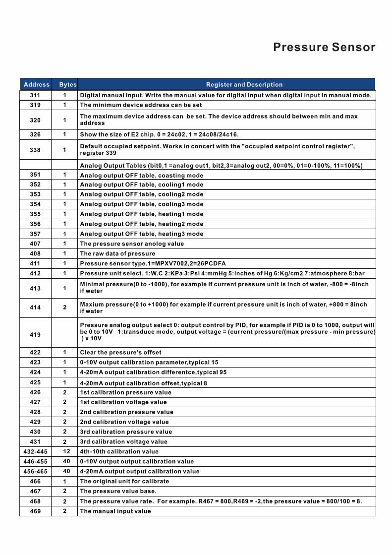
4-20mA output calibration differentce,typical 95
0-10V output calibration parameter,typical 15
Clear the pressure's offset
Pressure analog output select 0: output control by PID, for example if PID is 0 to 1000, output will be 0 to 10V 1:transduce mode, output voltage = (current pressure/(max pressure - min pressure) ) x 10V
Maxium pressure(0 to +1000) for example if current pressure unit is inch of water, +800 = 8inch if water
Minimal pressure(0 to -1000), for example if current pressure unit is inch of water, -800 = -8inch if water
Pressure unit select. 1:W.C 2:KPa 3:Psi 4:mmHg 5:inches of Hg 6:Kg/cm2 7:atmosphere 8:bar
Pressure sensor type.1=MPXV7002,2=26PCDFA
The raw data of pressure
The pressure sensor anolog value
Analog output OFF table, heating3 mode
Analog output OFF table, heating2 mode
Analog output OFF table, heating1 mode
Analog output OFF table, cooling3 mode
Analog output OFF table, cooling2 mode
Default occupied setpoint. Works in concert with the "occupied setpoint control register", register 339
Show the size of E2 chip. 0 = 24c02, 1 = 24c08/24c16.
Digital manual input. Write the manual value for digital input when digital input in manual mode.
352 1 Analog output OFF table, cooling1 mode
319 1 The minimum device address can be set
320 1The maximum device address can be set. The device address should between min and max address
351 1
Analog Output Tables (bit0,1 =analog out1, bit2,3=analog out2, 00=0%, 01=0-100%, 11=100%)
Analog output OFF table, coasting mode
Pressure Sensor
357 1
432-445
430
429
428
427
12
2
2
2
2
4th-10th calibration value
3rd calibration voltage value
3rd calibration pressure value
2nd calibration voltage value
2nd calibration pressure value
1st calibration voltage value
426 2 1st calibration pressure value
425 1 4-20mA output calibration offset,typical 8
431 2
467 2
40
40
The pressure value base.
The original unit for calibrate
4-20mA output output calibration value
0-10V output output calibration value
466 1
446-455
456-465
469 2 The manual input value
The pressure value rate. For example. R467 = 800,R469 = -2,the pressure value = 800/100 = 8.468 2
Register and DescriptionBytesAddress