pressure measurement remote seals for transmitters … · 1/270 siemens fi 01 · 2017 us edition...
TRANSCRIPT
1/269Siemens FI 01 · 2017 US Edition
Pressure MeasurementRemote seals for transmitters and pressure gauges
Technical description1
■ Application
The remote seals 7MF48.. can be fitted to SITRANS P transmit-ters for• pressure (SITRANS P300, P310, DSIII and P410),• absolute pressure (SITRANS P300 and DSIII) and• differential pressure and flow (SITRANS P310, DSIII, P410
and P500).
■ Design and mode of operation
A remote seal system consists of a transmitter, one or two remote seals, an appropriate transmission liquid, and a connection be-tween the transmitter and remote seal (direct mounting or capil-lary).
The volume in contact with the measured medium is defined by an flexible diaphragm. The volume between this diaphragm and the pressure transmitter is completely filled with a transmission fluid. If a pressure is now applied to the remote seal, this is trans-mitted via the flexible diaphragm and the fill fluid to the pressure transmitter.
In many cases, a capillary is located between the remote seal and the pressure transmitter in order e.g. to minimize tempera-ture effects from the hot medium on the latter. However, the cap-illary line influences the response time and the temperature re-sponse of the complete remote seal system. When fitting remote seals to differential pressure transmitters, two capillaries of the same length must always be used.
■ Fields of use
Remote seal systems should be used if a separation between the measured medium and the measuring instrument is appro-priate or essential for the following reasons:• The temperature of the medium is outside the limits speci-
fied for the transmitter.• The medium is corrosive and requires diaphragm materials in
the transmitter which are not available.• The medium is highly viscous or contains solids which
would block the measuring chambers of the transmitter.• The medium may freeze in the measuring chambers or
impulse line.• The medium is heterogeneous and fibrous. • The medium tends towards polymerization or crystallization.• The process requires quick-release remote seals, as neces-
sary e.g. in the food industry for fast cleaning.• The process requires cleaning of the measuring site, e.g. in a
batch process.
■ Constructional designs
A differentiation is made between diaphragm seals and inline seals.
With the diaphragm seals, the pressure is measured via a flat convoluted diaphragm welded to a convoluted backup.
With the inline seals, the pressure is measured via a cylindrical diaphragm positioned in a pipe, and transmitted to the transmit-ter via the filling liquid.
The inline seal is a special design for flowing media. It consists of a cylindrical pipe in which a cylindrical diaphragm is embed-ded. Since it is completely integrated in the process pipe, no tur-bulences, dead volumes or other obstructions to the flow occur.
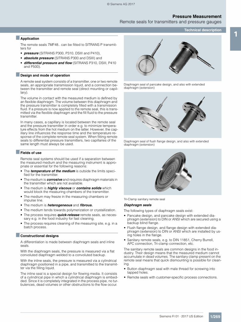
Diaphragm seal of pancake design, and also with extended diaphragm (extension)
Diaphragm seal of flush flange design, and also with extended diaphragm (extension)
Tri-Clamp sanitary remote seal
Diaphragm seals
The following types of diaphragm seals exist:• Pancake design, and pancake design with extended dia-
phragm (extension) to DIN or ANSI which are secured using a backup blind flange.
• Flush flange design, and flange design with extended dia-phragm (extension) to DIN or ANSI which are installed by us-ing holes in the flange.
• Sanitary remote seals, e.g. to DIN 11851, Cherry Burrell, APC connection, Tri-clamp connection, etc.
The sanitary remote seals are common designs in the food in-dustry. Their design means that the measured medium cannot accumulate in dead volumes. The sanitary clamp present on the remote seal means that quick dismounting is possible for clean-ing.• Button diaphragm seal with male thread for screwing into
tapped holes.• Remote seals with customer-specific process connections.
FI01_2017_us_kap01.book Seite 269 Dienstag, 8. August 2017 10:06 10
© Siemens AG 2017

1/270 Siemens FI 01 · 2017 US Edition
Pressure MeasurementRemote seals for transmitters and pressure gauges
Technical description1 Clamp-on seals
The following types of clamp-on seals exist:• Sanitary inline seals, e.g. to DIN 11851, Cherry Burrell, tri-
clamp connection etc. The sanitary facility enables the seal to be removed quickly for cleaning purposes.
• Inline seals for positioning between DIN or ANSI flanges.• Inline seals with customer-specific process connections.
■ Transmission response
Temperature errors occur if the fill fluid in the remote seal and in the capillaries expands or contracts as a result of temperature effects. The temperature error depends on the diaphragm cha-rateristic, the influence of the fill fluid, and the influence of the fill fluid under the process flanges or in the flanges on the transmit-ter (volume minimized for remote seals).
Diaphragm characteristicThe charateristic of the remote seal is of great importance. The larger the diaphragm diameter, the softer it is. In comparison to a smaller diaphragm, this means that it can respond far easier to temperature-based expansions of the filling liquid.The result is that low measuring ranges are only possible withlarge diaphragm diameters. In addition, the diaphragm thick-ness, its material, and any coatings which may be present mustalso be considered.
Fill fluidAll fill fluids expand or contract when the temperature varies. Temperature-independent errors can be minimized by selecting a suitable filling liquid, but it must also be ensured that the filling liquid is appropriate for the temperature limits and operating pressure. For food and beverage as well as pharmaceutical ap-plications see reference for FDA approved fill fluids.
Since the fill fluid is present under the remote seal diaphragm, in the capillaries and under the process flanges of the transmitter, the temperature error must be calculated separately for each combination.
Response timeThe response time depends on the internal diameter of the cap-illaries, the viscosity of the filling liquid, the capillary extension length, and the pressure in the measuring system:
Internal diameter:The response time decreases as the internal diameter increases, but the temperature error increases due to increased oil volume.
Viscosity:The response time increases as the viscosity increases.
Capillary length:The capillary length has a proportional effect on the response time and the temperature error.
Measuring system pressure:The response time decreases as the pressure in the measuring system increases.
■ Recommendations
The following should be observed to obtain an optimum combi-nation of transmitter and remote seal:• The remote seal diameter, and thus the effective diameter of
the diaphragm, should be selected as large as possible in or-der to keep the temperature-dependents errors as low as pos-sible.
• The capillaries should be selected as short as possible in or-der to keep the response time and the temperature-depen-dent errors as low as possible.
Button diaphragm seal with diaphragm flush with front
Sanitary tri-clamp seal and for flange pancake mounting
• A filling liquid should be selected which has the lowest viscos-ity and the lowest coefficient of expansion, and which simulta-neously fulfills the process requirements with respect to pres-sure/vacuum and temperature. The filling liquid must also be compatible with the process medium.
• When installing the equipment for vacuum applications, the transmitter must always be located below the lowest tap.
• It should also be noted that some of the filling liquids are very limited with respect to the permissible temperature of the me-dium for vacuum applications.
• When operating permanently at a vacuum, the remote seal must be designed in the version resistant to those vacuum ap-plicaton.
• Recommendations on the minimum span can be found in the tables on pages 1/271 and 1/272.
■ Note
The remote seals listed in this catalog are a selection of the most common designs. As a result of the large variety of process con-nections, it may nevertheless be the case that certain remote seals which are not listed in the catalog are still available.
Other versions could be:• Other process connections, standards• Aseptic or sterile connections• Other sizes• Other nominal pressures• Special diaphragm materials, including coatings• Other sealing faces• Other fill fluids• Other capillary lengths• Sheathing of capillaries with protective coat• Calibration at higher/lower temperatures etc.
Please contact your Siemens Regional Office for more information.
FI01_2017_us_kap01.book Seite 270 Dienstag, 8. August 2017 10:06 10
© Siemens AG 2017
1/271Siemens FI 01 · 2017 US Edition
Pressure MeasurementRemote seals for transmitters and pressure gauges
Technical description1
■ Technical specifications
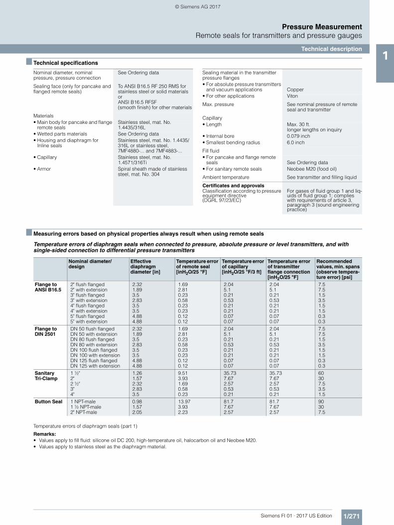
■ Measuring errors based on physical properties always result when using remote seals
Temperature errors of diaphragm seals when connected to pressure, absolute pressure or level transmitters, and with single-sided connection to differential pressure transmitters
Temperature errors of diaphragm seals (part 1)
Remarks:• Values apply to fill fluid: silicone oil DC 200, high-temperature oil, halocarbon oil and Neobee M20.• Values apply to stainless steel as the diaphragm material.
Nominal diameter, nominal pressure, pressure connection
See Ordering data
Sealing face (only for pancake and flanged remote seals)
To ANSI B16.5 RF 250 RMS for stainless steel or solid materials or ANSI B16.5 RFSF(smooth finish) for other materials
Materials• Main body for pancake and flange
remote sealsStainless steel, mat. No. 1.4435/316L
• Wetted parts materials See Ordering data • Housing and diaphragm for
Inline sealsStainless steel, mat. No. 1.4435/316L or stainless steel,7MF4880-... and 7MF4883-...
• Capillary Stainless steel, mat. No. 1.4571/316Ti
• Armor Spiral sheath made of stainlesssteel, mat. No. 304
Sealing material in the transmitterpressure flanges• For absolute pressure transmitters
and vacuum applications Copper• For other applications Viton
Max. pressure See nominal pressure of remote seal and transmitter
Capillary• Length Max. 30 ft.
longer lengths on inquiry• Internal bore 0.079 inch• Smallest bending radius 6.0 inch
Fill fluid• For pancake and flange remote
seals See Ordering data • For sanitary remote seals Neobee M20 (food oil)
Ambient temperature See transmitter and filling liquid
Certificates and approvalsClassification according to pressure equipment directive(DGRL 97/23/EC)
For gases of fluid group 1 and liq-uids of fluid group 1; complies with requirements of article 3, paragraph 3 (sound engineering practice)
Nominal diameter/design
Effective diaphragm diameter [in]
Temperature error of remote seal [inH2O/25 °F]
Temperature error of capillary [inH2O/25 °F/3 ft]
Temperature error of transmitter flange connection [inH2O/25 °F]
Recommended values, min. spans (observe tempera-ture error) [psi]
Flange to ANSI B16.5
2" flush flanged2" with extension3" flush flanged3" with extension4" flush flanged4" with extension5" flush flanged5" with extension
2.321.893.52.833.53.54.884.88
1.692.810.230.580.230.230.120.12
2.045.10.210.530.210.210.070.07
2.045.10.210.530.210.210.070.07
7.57.51.53.51.51.50.30.3
Flange to DIN 2501
DN 50 flush flangedDN 50 with extension DN 80 flush flangedDN 80 with extension DN 100 flush flangedDN 100 with extension DN 125 flush flangedDN 125 with extension
2.321.893.52.833.53.54.884.88
1.692.810.230.580.230.230.120.12
2.045.10.210.530.210.210.070.07
2.045.10.210.530.210.210.070.07
7.57.51.53.51.51.50.30.3
SanitaryTri-Clamp
1 ½"2"2 ½"3"4"
1.261.572.322.833.5
9.513.931.690.580.23
35.737.672.570.530.21
35.737.672.570.530.21
60307.53.51.5
Button Seal 1 NPT-male1 ½ NPT-male2" NPT-male
0.981.572.05
13.973.932.23
81.77.672.57
81.77.672.57
90307.5
FI01_2017_us_kap01.book Seite 271 Dienstag, 8. August 2017 10:06 10
© Siemens AG 2017

1/272 Siemens FI 01 · 2017 US Edition
Pressure MeasurementRemote seals for transmitters and pressure gauges
Technical description1 Temperature errors of diaphragm seals with double-sided connection to differential pressure transmitters
Temperature errors of diaphragm seals (part 2)
Remarks:• Values apply to fill fluids: silicone oil DC 200, high-temperature oil, halocarbon oil and Neobee M20.• Values apply to stainless steel as the diaphragm material.
Temperature errors of clamp-on seals when connected to pressure or absolute pressure transmitters, and with single-sided connection to differential pressure transmitters
Temperature errors of clamp-on seals with double-sided connection to differential pressure transmitters
Temperature errors of clamp-on seals
Remarks:• Values apply to fill fluids: silicone oil DC 200, high-temperature oil, halocarbon oil and Neobee M20.• Values apply to stainless steel as the diaphragm material.• Diaphragm thickness: 1" & 1 ½" & 2":0.002 inch
3" & 4": 0.004 inch
Nominal diameter/design
Effective diaphragm diameter [in]
Temperature error of remote seal [inH2O/25 °F]
Temperature error of capillary [inH2O/25 °F/3 ft]
Temperature error of transmitter flange connection [inH2O/25 °F]
Recommended values, min. spans (observe tempera-ture error) [psi]
Flange to ANSI B16.5
2" flush flanged2" with extension3" flush flanged3" with extension4" flush flanged4" with extension5" flush flanged5" with extension
2.321.893.52.833.53.54.884.88
0.3840.6920.0770.1540.0770.0770.0380.038
0.421.0510.0420.1260.0420.0420.0170.017
0.421.0510.0420.1260.0420.0420.0170.017
3.53.511.5110.30.3
Flange to DIN 2501
DN 50 flush flangedDN 50 with extension DN 80 flush flangedDN 80 with extension DN 100 flush flangedDN 100 with extension DN 125 flush flangedDN 125 with extension
2.321.893.52.833.53.54.884.88
0.3840.6920.0770.1540.0770.0770.0380.038
0.421.0510.0420.1260.0420.0420.0170.017
0.421.0510.0420.1260.0420.0420.0170.017
3.53.511.5110.30.3
SanitaryTri-Clamp
2"2 ½"3"4"
1.572.322.833.5
0.9610.3840.1540.077
1.8490.420.1260.042
1.8490.420.1260.042
303.51.51
Nominal diameter/design Temperature error of remote seal [inH2O/25 °F]
Temperature error of cap-illary [inH2O/25 °F/3 ft]
Temperature error of transmitter flange con-nection [inH2O/25 °F]
Recommended values, min. spans (observe tem-perature error) [psi]
1 inch1 ½ inch2 inch3 inch4 inch
3.3452.4992.235.3050.461
5.172.7321.8493.0681.849
5.172.7321.8493.0681.849
14.53.51.51.51.5
Nominal diameter/design Temperature error of remote seal [inH2O/25 °F]
Temperature error of cap-illary [inH2O/25 °F/3 ft]
Temperature error of transmitter flange con-nection [inH2O/25 °F]
Recommended values, min. spans (observe tem-perature error) [psi]
1 inch1 ½ inch2 inch3 inch4 inch
1.2690.4610.1541.6920.577
1.0930.1680.0840.2940.084
1.0930.1680.0840.2940.084
14.53.51.51.51.5
FI01_2017_us_kap01.book Seite 272 Dienstag, 8. August 2017 10:06 10
© Siemens AG 2017

1/273Siemens FI 01 · 2017 US Edition
Pressure MeasurementRemote seals for transmitters and pressure gauges
Technical description1Calculation of temperature error for remote seals
The following equation is used to calculate the temperature error for remote seals:
Example of calculation of temperature error for remote seals
Dependence of temperature error on diaphragm material
The errors listed in the tables on pages 1/271 and 1/272 refer to the use of stainless steel as the diaphragm material. If a different material is used, the listed values change by the amount shown in the following table.
Response times (approximate)
The listed values are the response times (in seconds, per meter of capillary extension) for a change in pressure which corre-sponds to the set span.
The listed values must be multiplied by the respective length of the capillary extension, or with transmitters for differential pres-sure and flow by the total length of both capillary extensions.
The response times are independent of the set span within the range of the respective transmitter. The response times are of insignificant importance for spans above 145 psi (10 bar). The response time of the transmitter has not been considered.
dp = (tRS - tCal) . fRS + (tCap - tCal) . lCap . fCap + (tTR - tCal) . fPF
dp Additional temperature error (inH2O)
tRS Temperature on remote seal diaphragm(generally corresponds to temperature of medium)
tCal Reference (calibration) temperature 68 °F
fRS Temperature error of remote seal (see tables on pages 1/271 and 1/272)
tCap Ambient temperature on the capillaries
lCap Capillary extension length (error given per 3 ft)
fCap Temperature error of capillaries (see tables on pages 1/271 and 1/272)
tTR Ambient temperature on transmitter
fPF Temperature error of oil filling in process flanges of transmitter (see tables on pages 1/271 and 1/272)
Existing conditions:
SITRANS P transmitter for differential pressure, 100 inH2O, set to 0 to 40 inH2O with 3 in flush flanged remote seal, diaphragm made of stainless steel, mat. No. 1.4535/316L
fRS = 0.054 inH2O/25 °F
Capillary 2 x 15 ft lCap = 2 x 15 ft
Capillaries fitted on both sides fCap= 0.042 inH2O/25 °F/3 ft
Filled with silicone oil DC 200-10 fPF = 0.042 inH2O/25 °F
Temperature of medium 212 °F tRS = 212 °F
Temperature on capillaries 122 °F tCap = 122 °F
Temperature on transmitter 122 °F tTR = 122 °F
Required:
Additional temperature error of remote seal: dp
Calculation:
dp = (212 °F – 68 °F) . 0.077 inH2O/25 °F + (122 °F – 68 °F) . 15 ft. 2 . 0.042 inH2O/25 °F / 3ft + (122 °F – 68 °F) . 0.042 inH2O/25 °Fdp = 0.444 inH2O + 0.907 inH2O + 0.091 inH2O
Result:
dp = 1.442 inH2O (corresponds to 3.605 % of set span)
Note:The temperature error determined above only applies to the errorresulting from connection of the remote seal.The transmission response of the respective transmitter is not included in this consideration. It must be calculated separately, and the resulting error added to the error determined above from connection of the remote seal.
Diaphragm material Change in temperature error of remote seal
Stainless steel Values as specified in tables on pages 1/271 and 1/272
Hastelloy C4, mat. No. 2.4610 Increase in values by 50%
Hastelloy C276, mat. No. 2.4819 Increase in values by 50%
Monel 400, mat. No. 2.4360 Increase in values by 60%
Tantalum Increase in values by 50%
Titanium Increase in values by 50%
Gold coating on stainless steel diaphragm
Increase in values by 40%
FI01_2017_us_kap01.book Seite 273 Dienstag, 8. August 2017 10:06 10
© Siemens AG 2017

1/274 Siemens FI 01 · 2017 US Edition
Pressure MeasurementRemote seals for transmitters and pressure gauges
Technical description1
■ Technical specifications of filling liquid
When selecting the filling liquid, check that it is suitable with respect to the permissible temperature of the medium and the process pressure. Also check the compatibility with the mea-sured medium. For example, only food grade filling liquids may be used in the food industry. A special case are oxygen and chlorine as the measured media; the fill fluid must not react with them, otherwise an explosion or fire may occur if there is a leak in the remote seal.
■ Maximum temperature of medium
The following maximum temperatures of the medium apply depending on the wetted parts materials:
■ Maximum capillary length (guidance values for diaphragm seals and inline seals)
Filling liquid Density Temperature on capillary Response time in s/m (s/ft) with max. span of transmitter
kg/dm3 (lb/in3) °C (°F) 250 mbar (3.63 psi) 600 mbar (8.7 psi) 1600 mbar (23.2 psi)
Silicone oil DC 200-10
0.934 (0.033) +60+20- 20
(140)(68)(-4)
0.060.110.3
(0.018)(0.034)(0.091)
0.020.020.12
(0.006)(0.006)(0.037)
0.010.020.05
(0.003)(0.006)(0.015)
Silicone oilDC 200-50
0.966 (0.035) +60+20- 20
(140)(68)(-4)
0.60.611.69
(0.183)(0.186)(0.515)
0.250.260.71
(0.076)(0.079)(0.216)
0.090.10.27
(0.027)(0.030)(0.082)
Syltherm 800 0.935 (0.034) +60+20- 20
(140)(68)(-4)
0.060.110.3
(0.018)(0.034)(0.091)
0.020.020.12
(0.006)(0.006)(0.37)
0.010.020.05
(0.003)(0.006)(0.015)
Silicone oil DC704
1.07 (0.039) +60+20-10
(140)(68)(14)
0.140.653.96
(0.043)(0.198)(1.207)
0.060.271.65
(0.018)(0.082)(0.503)
0.020.10.62
(0.006)(0.030)(0.189)
Halocarbon oil 1.968 (0.071) +60+20- 20
(140)(68)(68)
0.070.292.88
(0.021)(0.088)(0.878)
0.030.121.2
(0.009)(0.037)(0.366)
0.010.050.45
(0.003)(0.015)(0.137)
Fluorolube 1.866 (0.068) +60+20- 20
(140)(68)(68)
0.070.292.88
(0.021)(0.088)(0.878)
0.030.121.2
(0.009)(0.037)(0.366)
0.010.050.45
(0.003)(0.015)(0.137)
Neobee M20 0.917 (0.033) +60+20- 20
(140)(68)(68)
0.180.431.19
(0.055)(0.131)(0.363)
0.080.180.5
(0.024)(0.055)(0.152)
0.030.070.18
(0.009)(0.021)(0.055)
Glycerine/water 1.22 (0.044) +60+20
0
(140)(68)(32)
0.130.769.72
(0.040)(0.232)(2.963)
0.050.324.05
(0.015)(0.098)(12.34)
0.020.121.51
(0.006)(0.037)(0.460)
Filling liquid Permissible temperature of medium Density at 20 °C (68 °F)
Viscosity at 20 °C (68 °F)
Expansion coefficient
pabs<1 bar (pabs<14.5 psi) pabs>1 bar (pabs>14.5 psi) kg/dm3 (lb/in3) m2/s·106 (ft2/s·106) 1/°C (1/°F)
°C (°F) °C (°F)
Silicone oilDC200-10
-40 to +121 (-40 to +248) -40 to +200 (-40 to +392) 0.934 (0.03) 10 (107.6) 0.00108 (0.00060)
Silicone oil DC 200-50
-20 to +150 (-4 to +302) -20 to +250 (-4 to +482) 0.96 (0.03) 50 (538) 0.00104 (0.00058)
Syltherm 800 -40 to +121 (-40 to +250) -40 to +205 (-40 to +400) 0.935 (0.034) 10.03 (107.9) 0.00109 (0.00061)
Silicone oilDC704
-10 to +200 (+14 to +392) -10 to +350 (+14 to +662) 1.07 (0.04) 39 (420) 0.0008 (0.00044)
Halocarbon oil -40 to +80 (-40 to +176) -40 to +175 (-40 to +347) 1.968 (0.07) 14 (151) 0.00086 (0.00048)
Fluorolube Not possible Not possible -40 to +175 (-40 to +347) 1.866 (0.068) 15.5 (167) 0.000864 (0.00048)
Neobee M20 10 to +90 (+14 to +195) -10 to +200 (+14 to +392) 0.917 (0.03) 9.8 (105) 0.00082 (0.00045)
Glycerine/water Not possible Not possible -10 to +120 (+14 to +248) 1.22 (0.04) 88 (947) 0.0005 (0.00028)
Material pabs < 1 bar (14.5 psi)
pabs > 1 bar (14.5 psi)
°C (°F) °C (°F)
Stainless steel, mat. No. 1.4571/316Ti 200 (392) 350 (662)Hastelloy C4, mat. No. 2.4610 200 (392) 350 (662)Hastelloy C276, mat. No. 2.4819 200 (392) 350 (662)Monel 400, mat. No. 2.4360 200 (392) 350 (662)Tantalum 200 (392) 300 (572)
Nominal diameter Max. length of capillary
Diaphragm seal Inline seal
DN 25 (1 inch) 2.5 m (8.2 ft) 2.5 m (8.2 ft)
DN 32 (1¼ inch) 2.5 m (4.9 ft) 2.5 m (8.2 ft)
DN 40 (1½ inch) 4 m (13.1 ft) 6 m (19.7 ft)
DN 50 (2 inch) 6 m (19.7 ft) 10 m (32.8 ft)
DN 65 (2½ inch) 8 m (26.2 ft) 10 m (32.8 ft)
DN 80 (3 inch) 10 m (32.8 ft) 10 m (32.8 ft)
Size 4 inch (30.0 ft) –
Size 5 inch (30.0 ft) – –
FI01_2017_us_kap01.book Seite 274 Dienstag, 8. August 2017 10:06 10
© Siemens AG 2017
1/275Siemens FI 01 · 2017 US Edition
Pressure MeasurementRemote seals for transmitters and pressure gauges
Pancake type diaphragm seal with flexible capillary tube1
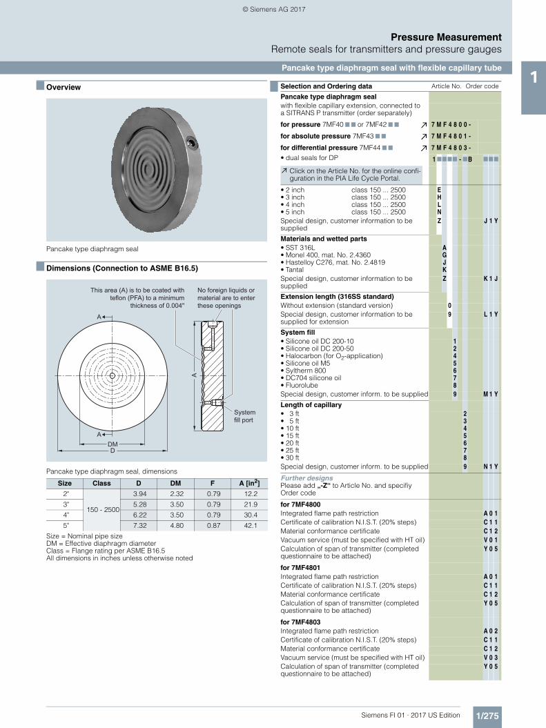
■ Overview
Pancake type diaphragm seal
■ Dimensions (Connection to ASME B16.5)
Pancake type diaphragm seal, dimensions
Size Class D DM F A [in2]
2"
150 - 2500
3.94 2.32 0.79 12.2
3" 5.28 3.50 0.79 21.9
4" 6.22 3.50 0.79 30.4
5" 7.32 4.80 0.87 42.1
Size = Nominal pipe sizeDM = Effective diaphragm diameterClass = Flange rating per ASME B16.5All dimensions in inches unless otherwise noted
This area (A) is to be coated with teflon (PFA) to a minimum
thickness of 0.004"
System fill port
No foreign liquids or material are to enter these openings
A
A
DMD
A
Selection and Ordering data Article No. Order code
Pancake type diaphragm sealwith flexible capillary extension, connected to a SITRANS P transmitter (order separately)
for pressure 7MF40 7 7 or 7MF42 7 7 7 M F 4 8 0 0 -
for absolute pressure 7MF43 7 7 7 M F 4 8 0 1 -
for differential pressure 7MF44 7 7
• dual seals for DP7 M F 4 8 0 3 -
1 7777 - 7B 777
Click on the Article No. for the online confi-guration in the PIA Life Cycle Portal.
• 2 inch• 3 inch• 4 inch• 5 inch
class 150 ... 2500class 150 ... 2500class 150 ... 2500class 150 ... 2500
EHLN
Special design, customer information to be supplied
Z J 1 Y
Materials and wetted parts• SST 316L• Monel 400, mat. No. 2.4360• Hastelloy C276, mat. No. 2.4819• Tantal
AGJK
Special design, customer information to be supplied
Z K 1 J
Extension length (316SS standard)Without extension (standard version) 0Special design, customer information to be supplied for extension
9 L 1 Y
System fill• Silicone oil DC 200-10• Silicone oil DC 200-50• Halocarbon (for O2-application)• Silicone oil M5• Syltherm 800• DC704 silicone oil• Fluorolube
1245678
Special design, customer inform. to be supplied 9 M 1 Y
Length of capillary• 3 ft• 5 ft• 10 ft• 15 ft• 20 ft• 25 ft• 30 ft
2345678
Special design, customer inform. to be supplied 9 N 1 Y
Further designsPlease add „-Z“ to Article No. and specifiy Order code
for 7MF4800Integrated flame path restriction A 0 1Certificate of calibration N.I.S.T. (20% steps) C 1 1Material conformance certificate C 1 2Vacuum service (must be specified with HT oil) V 0 1Calculation of span of transmitter (completed questionnaire to be attached)
Y 0 5
for 7MF4801Integrated flame path restriction A 0 1Certificate of calibration N.I.S.T. (20% steps) C 1 1Material conformance certificate C 1 2Calculation of span of transmitter (completed questionnaire to be attached)
Y 0 5
for 7MF4803Integrated flame path restriction A 0 2Certificate of calibration N.I.S.T. (20% steps) C 1 1Material conformance certificate C 1 2Vacuum service (must be specified with HT oil) V 0 3Calculation of span of transmitter (completed questionnaire to be attached)
Y 0 5
FI01_2017_us_kap01.book Seite 275 Dienstag, 8. August 2017 10:06 10
© Siemens AG 2017

1/276 Siemens FI 01 · 2017 US Edition
Pressure MeasurementRemote seals for transmitters and pressure gauges
Flange-type diaphragm seal directly connected1
■ Overview
Flange-type diaphragm seal, without extension
■ Dimensions (connection to ASME B16.5)
Flange-type diaphragm seal without extension for flanges ≤ 1"
Flange-type diaphragm seal without extension for flanges ≥ 1.5"
Flange-type diaphragm seal, without extension, dimensions
Optional instrumentWelded capillaryconnection1/4” NPT1/2“ NPT
Optional instrumentconnectionswelded capillaryconnection1/4” NPT1/2“ NPT
Systemfill port
Size Class A B C DM E F G X Weight
DN lbs
½"150 3.50 2.38 1.38 1.3 0.85 0.06 0.62 4 2.2
300 3.75 2.62 1.38 1.6 0.85 0.06 0.62 4 2.2
¾"150 3.88 2.75 1.69 1.6 0.85 0.06 0.62 4 2.4
300 4.62 3.25 1.69 1.6 0.85 0.06 0.75 4 3.5
1"150 4.25 3.12 2.00 2.1 0.85 0.06 0.62 4 3.1
300 4.88 3.50 2.00 2.1 0.85 0.06 0.75 4 3.7
1.5"
150 5.00 3.55 2.88 1.9 0.69 0.06 0.62 4 3.5
300 6.12 4.50 2.88 1.9 0.81 0.06 0.88 4 5.5
600 6.12 4.50 2.88 1.9 1.13 0.25 0.88 4 7.3
1500 7.00 4.88 2.88 1.9 1.50 0.25 1.12 4 13.0
2500 8.00 5.75 2.88 1.9 2.00 0.25 1.25 4 22.9
2"
150 6.00 4.75 3.62 2.4 0.75 0.06 0.75 4 5.9
300 6.50 5.00 3.62 2.4 0.88 0.06 0.75 8 8.1
600 6.50 5.00 3.62 2.4 1.25 0.25 0.75 8 12.5
1500 8.50 6.50 3.62 2.4 1.75 0.25 1.00 8 29.0
2500 9.25 6.75 3.62 2.4 2.25 0.25 1.12 8 43.6
3"
150 7.50 6.00 5.00 3.5 0.94 0.06 0.75 4 11.7
300 8.25 6.62 5.00 3.5 1.12 0.06 0.88 8 17.2
600 8.25 6.62 5.00 3.5 1.50 0.25 0.88 8 24.2
900 9.50 7.50 5.00 3.5 1.75 0.25 1.00 8 36.7
1500 10.53 8.00 5.00 3.5 2.13 0.25 1.25 8 53.9
2500 12.01 9.00 5.00 3.5 2.87 0.25 1.38 8 93.9
4"
150 9.00 7.50 6.19 3.5 0.94 0.06 0.75 8 16.9
300 10.04 7.88 6.19 3.5 1.25 0.06 0.88 8 27.9
400 10.4 7.88 6.19 3.5 1.63 0.25 1.00 8 38.3
600 10.83 8.50 6.19 3.5 1.75 0.25 1.00 8 47.3
900 11.51 9.25 6.19 3.5 2.00 0.25 1.25 8 60.9
1500 12.30 9.50 6.19 3.5 2.37 0.25 1.38 8 81.4
2500 14.00 10.75 6.19 3.5 3.25 0.25 1.62 8 144.5
DN = Nominal pipe sizeDM = Effective diaphragm diameterClass = Flange rating per ASME B16.5X = Number of bolt holesAll dimensions in inches unless otherwise noted
FI01_2017_us_kap01.book Seite 276 Dienstag, 8. August 2017 10:06 10
© Siemens AG 2017

1/277Siemens FI 01 · 2017 US Edition
Pressure MeasurementRemote seals for transmitters and pressure gauges
Flange-type diaphragm seal with extension1
■ Overview
Flange-type diaphragm seal, with extension
■ Dimensions
Flange-type diaphragm seal, with extension, dimensions
Size Class A B C DM E1) F G H X L
DN
2" 150 6.00 4.753.62 1.8 1.90
0.75
0.06
0.75 4
2.0 3.0 4.0 6.0
300 6.50 5.00 0.88 0.75 8
3" 150 7.50 6.005.00 2.8 2.99
0.94 0.75 4
300 8.25 6.62 1.12 0.88 8
4" 150 9.00 7.506.19 3.5 3.70
0.94 0.75 8
300 10.04 7.88 1.25 0.88 81) based on schedule 40DN = Nominal pipe sizeDM = Effective diaphragm diameterClass = Flange rating per ASME B16.5X = Number of bolt holesAll dimensions in inches unless otherwise noted
Instrument connectionOptionsWelded capillary connection1/4” NPT1/2“ NPT
Selection and Ordering data Article No. Order code
Flange-type diaphragm seal
directly connected to a SITRANS P 7MF40 7 7 or 7MF42 7 7(order separately)
7 M F 4 8 1 0 -
77777 777
Click on the Article No. for the online confi-guration in the PIA Life Cycle Portal.
Process connectionvertical (transmitter upright)horizontal
02
Size and class• 2 inch• 2 inch• 2 inch• 2 inch• 3 inch• 3 inch• 3 inch• 4 inch• 4 inch• 4 inch
class 150class 300class 600class 1500class 150class 300class 600class 150class 300class 400
LMNP
QRS
TUV
Special design, customer information to be supplied
Z J 1 Y
Materials and wetted parts• SST 316L• Monel 400, mat. No. 2.4360• Hastelloy C276, mat. No. 2.4819• Tantal
AGJK
Special design, customer information to be supplied
Z K 1 Y
Extension length (316SS standard)Without extension (standard version)2"4"6"8"
01234
Special design, customer information to be supplied for extension
9 L 1 Y
System fill• Silicone oil DC 200-10• Silicone oil DC 200-50• Halocarbon (for O2-application)• Silicone oil M5• Syltherm 800• DC704 silicone oil• Fluorolube
1245678
Special design, customer information to be supplied
9 M 1 Y
Further designsPlease add „-Z“ to Article No. and specifiy Order code
Integrated flame path restrictionRotatable FlangeCertification of calibration N.I.S.T. (20% steps)Material conformance certificateVacuum service (must be specified with HT oil)Calculation of span of transmitter (completed questionnaire to be attached)
A
B
C
C
V
Y
0
0
1
1
0
0
1
1
1
2
1
5
FI01_2017_us_kap01.book Seite 277 Dienstag, 8. August 2017 10:06 10
© Siemens AG 2017

1/278 Siemens FI 01 · 2017 US Edition
Pressure MeasurementRemote seals for transmitters and pressure gauges
Flange-type diaphragm seal with extension1
Selection and Ordering data Article No. Order code
Mounting flange
directly mounted at SITRANS P for Level 7MF46 7 7 (order separately)
7 M F 4 8 1 2 -
3 7777 777
Click on the Article No. for the online confi-guration in the PIA Life Cycle Portal.
Flange Size Class
ANSI B16.5 2 inch
3 inch
4 inch
150300150300150300
LMQRTU
Special design, customer information to be supplied
Z J 1 Y
Materials and wetted parts• SST 316L• Monel 400, mat. No. 2.4360• Hastelloy C276, mat. No. 2.4819• Tantal
AGJK
Special design, customer information to be supplied
Z K 1 Y
Extension length (316SS standard)Without extension (standard version, 0 mm)2" 50 mm4" 100 mm6" 150 mm8" 200 mm
01234
Special design, customer information to be supplied for extension
9 L 1 Y
System fill• Silicone oil DC 200-10• Silicone oil DC 200-50• Halocarbon (for O2-application)• Silicone oil M5• Syltherm 800• DC704 silicone oil• Fluorolube
1245678
Special design, customer information to be supplied
9 M 1 Y
Further designsPlease add „-Z“ to Article No. and specifiy Order code
Integrated flame path restrictionRotatable FlangeCertificates:Certification of calibration N.I.S.T. (20% steps)Material conformance certificateVacuum service (must be specified with HT oil)Calculation of span of transmitter (completed questionnaire to be attached)
A
B
C
C
V
Y
0
0
1
1
0
0
1
1
1
2
4
5
Selection and Ordering data Article No. Order code
Mounting flange at High-Side, Flange-Type Seal, w/o extension Flange-type seal via capillary extension on low-side without extension
for SITRANS P for differential pressure 7MF44 7 7 (order separately)
7 M F 4 8 1 3 -
1 7777 - 7B 777
Click on the Article No. for the online confi-guration in the PIA Life Cycle Portal.
Flange Size Class
ANSI B16.5 2 inch
3 inch
4 inch
150300150300150300
LMQRTU
Special design, customer information to be supplied
Z J 1 Y
Materials and wetted parts• SST 316L• Monel 400, mat. No. 2.4360• Hastelloy C276, mat. No. 2.4819• Tantal
AGJK
Special design, customer information to be supplied
Z K 1 Y
Extension length (316SS standard)Without extension (standard version, 0 mm)2" 50 mm4" 100 mm6" 150 mm8" 200 mm
01234
Special design, customer information to be supplied for extension
9 L 1 Y
System fill• Silicone oil DC 200-10• Silicone oil DC 200-50• Halocarbon (for O2-application)• Silicone oil M5• Syltherm 800• DC704 silicone oil• Fluorolube
1245678
Special design, customer information to be supplied
9 M 1 Y
Capillary length at low-side• 3 ft• 5 ft• 10 ft• 15 ft• 20 ft• 25 ft• 30 ft
2345678
Special design, customer information to be supplied
9
Further designsPlease add „-Z“ to Article No. and specifiy Order code
Integrated flame path restrictionRotatable FlangeCertification of calibration N.I.S.T. (20% steps)Material conformance certificateVacuum service (must be specified with HT oil)Calculation of span of transmitter (completed questionnaire to be attached)
A
B
C
C
V
Y
0
0
1
1
0
0
2
1
1
2
4
5
FI01_2017_us_kap01.book Seite 278 Dienstag, 8. August 2017 10:06 10
© Siemens AG 2017

1/279Siemens FI 01 · 2017 US Edition
Pressure MeasurementRemote seals for transmitters and pressure gauges
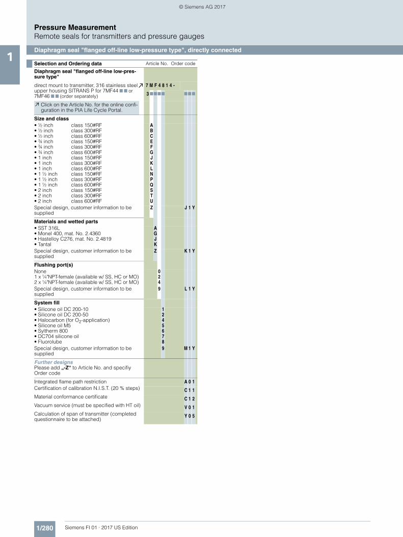
Diaphragm seal "flanged off-line low-pressure type", directly connected1
■ Overview
Diaphragm seal "flanges off-line low-pressure type"
■ Dimensions (Connection to ASME B16.5)
G2 G3 X A B C DM ESize Class½" 150# ½"-13UNC 4 5.91
5.91
0.06
3.5
2.36½" 300# ½"-13UNC 4 5.91 0.06 2.36½" 600# ½"-13UNC 4 5.91 0.25 2.55¾" 150# ½"-13UNC 4 5.91 0.06 2.36¾" 300# 5/8"-11UNC 4 5.91 0.06 2.36¾" 600# 5/8"-11UNC 4 5.91 0.25 2.551" 150# ½"-13UNC 4 5.91 0.06 2.361" 300# 5/8"-11UNC 4 5.91 0.06 2.361" 600# 5/8"-11UNC 4 5.91 0.25 2.55
1 ½" 150# ½"-13UNC 4 5.91 0.06 2.361 ½" 300# ¾"-10UNC 4 6.12 0.06 2.461 ½" 600# ¾"-10UNC 4 6.12 0.25 2.65
2" 150# 5/8"-11UNC 4 6.00 0.06 2.362" 300# 5/8"-11UNC 8 6.50 0.06 2.362" 600# 5/8"-11UNC 8 6.50 0.25 2.55
Instrument connection optionswelded capillary connection1/4” NPT1/2“ NPT
DM = Effective diaphragm diameterG1 = Instrument connectionG2 = Process connectionG3 = Threaded bolt holeX = Number of bolt holesClass = Flange rating per ASME B16.5Size = Nominal pipe sizeAll dimensions in inches unless otherwise noted
FI01_2017_us_kap01.book Seite 279 Dienstag, 8. August 2017 10:06 10
© Siemens AG 2017
1/280 Siemens FI 01 · 2017 US Edition
Pressure MeasurementRemote seals for transmitters and pressure gauges
Diaphragm seal "flanged off-line low-pressure type", directly connected1
Selection and Ordering data Article No. Order code
Diaphragm seal "flanged off-line low-pres-sure type"
direct mount to transmitter, 316 stainless steel upper housing SITRANS P for 7MF44 7 7 or 7MF46 7 7 (order separately)
7 M F 4 8 1 4 -
3 7777 777
Click on the Article No. for the online confi-guration in the PIA Life Cycle Portal.
Size and class• ½ inch• ½ inch• ½ inch• ¾ inch• ¾ inch• ¾ inch• 1 inch• 1 inch• 1 inch• 1 ½ inch• 1 ½ inch• 1 ½ inch• 2 inch• 2 inch• 2 inch
class 150#RFclass 300#RFclass 600#RFclass 150#RFclass 300#RFclass 600#RFclass 150#RFclass 300#RFclass 600#RFclass 150#RFclass 300#RFclass 600#RFclass 150#RFclass 300#RFclass 600#RF
ABCEFGJKLNPQSTU
Special design, customer information to be supplied
Z J 1 Y
Materials and wetted parts• SST 316L• Monel 400, mat. No. 2.4360• Hastelloy C276, mat. No. 2.4819• Tantal
AGJK
Special design, customer information to be supplied
Z K 1 Y
Flushing port(s)None1 x ¼"NPT-female (available w/ SS, HC or MO)2 x ¼"NPT-female (available w/ SS, HC or MO)
024
Special design, customer information to be supplied
9 L 1 Y
System fill• Silicone oil DC 200-10• Silicone oil DC 200-50• Halocarbon (for O2-application)• Silicone oil M5• Syltherm 800• DC704 silicone oil• Fluorolube
1245678
Special design, customer information to be supplied
9 M 1 Y
Further designsPlease add „-Z“ to Article No. and specifiy Order code
Integrated flame path restriction A 0 1Certification of calibration N.I.S.T. (20 % steps) C 1 1Material conformance certificate C 1 2Vacuum service (must be specified with HT oil) V 0 1Calculation of span of transmitter (completed questionnaire to be attached)
Y 0 5
FI01_2017_us_kap01.book Seite 280 Dienstag, 8. August 2017 10:06 10
© Siemens AG 2017

1/281Siemens FI 01 · 2017 US Edition
Pressure MeasurementRemote seals for transmitters and pressure gauges
Flange-type diaphragm seal with flexible capillary tube1
■ Overview
Flange-type diaphragm seal with flexible capillary extension
■ Dimensions (Connection to ASME B16.5)
Flange-type diaphragm seal for flanges ≤ 1"
Flange-type diaphragm seal for flanges ≥ 1.5"
■ Connection to ASME B16.5
Optional instrumentWelded capillaryconnection1/4” NPT1/2” NPT
Optional instrumentconnectionswelded capillaryconnection1/4” NPT1/2” NPT
Systemfill port
Size Class A B C DM E F G X Weight
DN lbs
½"150 3.50 2.38 1.38 1.3 0.85 0.06 0.62 4 2.2
300 3.75 2.62 1.38 1.6 0.85 0.06 0.62 4 2.2
¾"150 3.88 2.75 1.69 1.6 0.85 0.06 0.62 4 2.4
300 4.62 3.25 1.69 1.6 0.85 0.06 0.75 4 3.5
1"150 4.25 3.12 2.00 2.1 0.85 0.06 0.62 4 3.1
300 4.88 3.50 2.00 2.1 0.85 0.06 0.75 4 3.7
1.5"
150 5.00 3.55 2.88 1.9 0.69 0.06 0.62 4 3.5
300 6.12 4.50 2.88 1.9 0.81 0.06 0.88 4 5.5
600 6.12 4.50 2.88 1.9 1.13 0.25 0.88 4 7.3
1500 7.00 4.88 2.88 1.9 1.50 0.25 1.12 4 13.0
2500 8.00 5.75 2.88 1.9 2.00 0.25 1.25 4 22.9
2"
150 6.00 4.75 3.62 2.4 0.75 0.06 0.75 4 5.9
300 6.50 5.00 3.62 2.4 0.88 0.06 0.75 8 8.1
600 6.50 5.00 3.62 2.4 1.25 0.25 0.75 8 12.5
1500 8.50 6.50 3.62 2.4 1.75 0.25 1.00 8 29.0
2500 9.25 6.75 3.62 2.4 2.25 0.25 1.12 8 43.6
3"
150 7.50 6.00 5.00 3.5 0.94 0.06 0.75 4 11.7
300 8.25 6.62 5.00 3.5 1.12 0.06 0.88 8 17.2
600 8.25 6.62 5.00 3.5 1.50 0.25 0.88 8 24.2
900 9.50 7.50 5.00 3.5 1.75 0.25 1.00 8 36.7
1500 10.53 8.00 5.00 3.5 2.13 0.25 1.25 8 53.9
2500 12.01 9.00 5.00 3.5 2.87 0.25 1.38 8 93.9
4"
150 9.00 7.50 6.19 3.5 0.94 0.06 0.75 8 16.9
300 10.04 7.88 6.19 3.5 1.25 0.06 0.88 8 27.9
400 10.4 7.88 6.19 3.5 1.63 0.25 1.00 8 38.3
600 10.83 8.50 6.19 3.5 1.75 0.25 1.00 8 47.3
900 11.51 9.25 6.19 3.5 2.00 0.25 1.25 8 60.9
1500 12.30 9.50 6.19 3.5 2.37 0.25 1.38 8 81.4
2500 14.00 10.75 6.19 3.5 3.25 0.25 1.62 8 144.5
DN = Nominal pipe sizeDM = Effective diaphragm diameterClass = Flange rating per ASME B16.5X = Number of bolt holesAll dimensions in inches unless otherwise noted
FI01_2017_us_kap01.book Seite 281 Dienstag, 8. August 2017 10:06 10
© Siemens AG 2017
1/282 Siemens FI 01 · 2017 US Edition
Pressure MeasurementRemote seals for transmitters and pressure gauges
Flange-type diaphragm seal with flexible capillary tube1
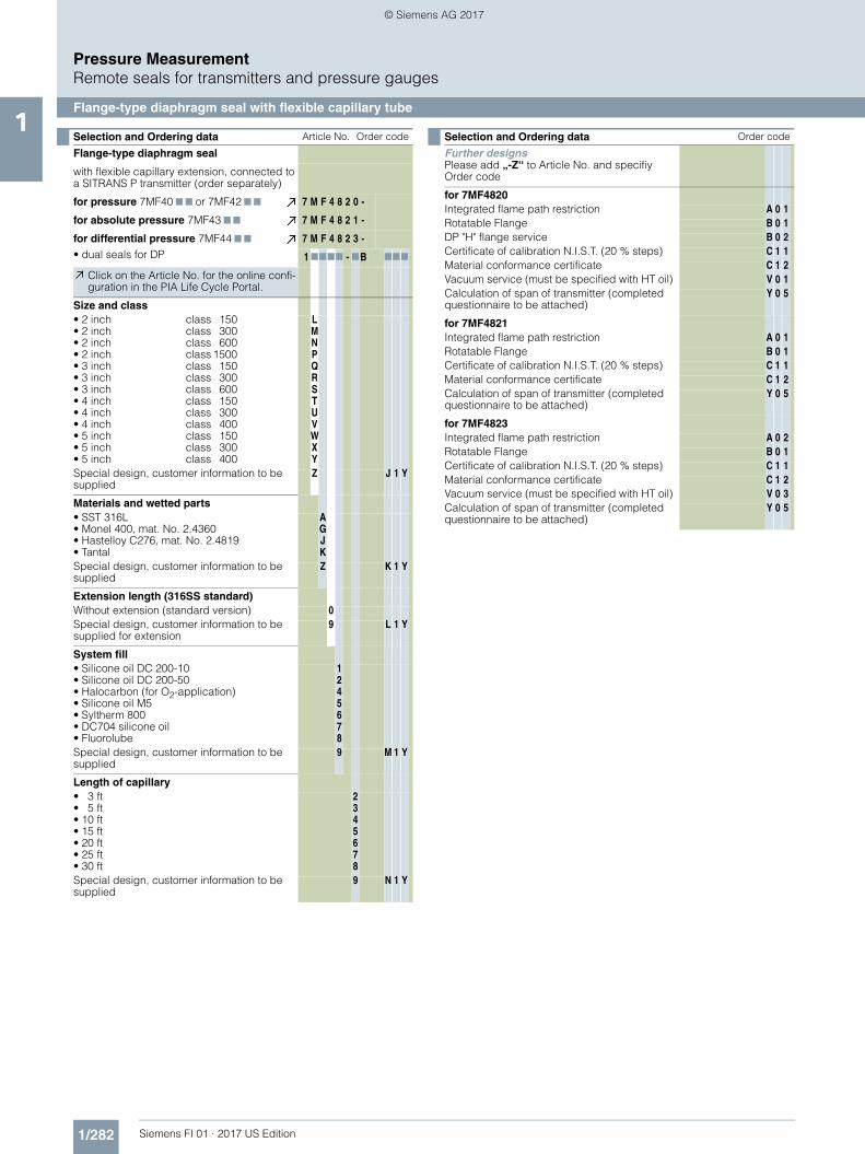
Selection and Ordering data Article No. Order code
Flange-type diaphragm seal
with flexible capillary extension, connected to a SITRANS P transmitter (order separately)
for pressure 7MF40 7 7 or 7MF42 7 7 7 M F 4 8 2 0 -
for absolute pressure 7MF43 7 7 7 M F 4 8 2 1 -
for differential pressure 7MF44 7 7
• dual seals for DP7 M F 4 8 2 3 -
1 7777 - 7B 777
Click on the Article No. for the online confi-guration in the PIA Life Cycle Portal.
Size and class• 2 inch• 2 inch• 2 inch• 2 inch• 3 inch• 3 inch• 3 inch• 4 inch• 4 inch• 4 inch• 5 inch• 5 inch• 5 inch
class 150class 300class 600class 1500class 150class 300class 600class 150class 300class 400class 150class 300class 400
LMNPQRSTUVWXY
Special design, customer information to be supplied
Z J 1 Y
Materials and wetted parts• SST 316L• Monel 400, mat. No. 2.4360• Hastelloy C276, mat. No. 2.4819• Tantal
AGJK
Special design, customer information to be supplied
Z K 1 Y
Extension length (316SS standard)Without extension (standard version) 0Special design, customer information to be supplied for extension
9 L 1 Y
System fill• Silicone oil DC 200-10• Silicone oil DC 200-50• Halocarbon (for O2-application)• Silicone oil M5• Syltherm 800• DC704 silicone oil• Fluorolube
1245678
Special design, customer information to be supplied
9 M 1 Y
Length of capillary• 3 ft• 5 ft• 10 ft• 15 ft• 20 ft• 25 ft• 30 ft
2345678
Special design, customer information to be supplied
9 N 1 Y
Selection and Ordering data Order code
Further designsPlease add „-Z“ to Article No. and specifiy Order code
for 7MF4820Integrated flame path restriction A 0 1Rotatable Flange B 0 1DP "H" flange service B 0 2Certificate of calibration N.I.S.T. (20 % steps) C 1 1Material conformance certificate C 1 2Vacuum service (must be specified with HT oil) V 0 1Calculation of span of transmitter (completed questionnaire to be attached)
Y 0 5
for 7MF4821Integrated flame path restriction A 0 1Rotatable Flange B 0 1Certificate of calibration N.I.S.T. (20 % steps) C 1 1Material conformance certificate C 1 2Calculation of span of transmitter (completed questionnaire to be attached)
Y 0 5
for 7MF4823Integrated flame path restriction A 0 2Rotatable Flange B 0 1Certificate of calibration N.I.S.T. (20 % steps) C 1 1Material conformance certificate C 1 2Vacuum service (must be specified with HT oil) V 0 3Calculation of span of transmitter (completed questionnaire to be attached)
Y 0 5
FI01_2017_us_kap01.book Seite 282 Dienstag, 8. August 2017 10:06 10
© Siemens AG 2017

1/283Siemens FI 01 · 2017 US Edition
Pressure MeasurementRemote seals for transmitters and pressure gauges
Diaphragm seal "flanged off-line type"1
■ Overview
Diaphragm seal "flanged off-line type"
■ Dimensions (Connection to ASME B16.5)
Diaphragm seal "flanged off-line type", dimensions
Instrumentconnection
Instrumentconnection
Systemfill port
Optional1/8” NPTor 1/4” NPTflushingconnection
Systemfill port
G1 G2 G3 A B C DM E
¼"-NPTor
½"-NPT
½" 150# 4 x ½"-13UNC 3.75 2.381.38
2.1 3.74
½" 300# 4 x ½"-13UNC 3.75 2.62½" 600# 4 x ½"-13UNC 3.75 2.621" 150# 4 x ½"-13UNC 4.25 3.12
2.001" 300# 4 x 5/8"-11UNC 4.88 3.501" 600# 4 x 5/8"-11UNC 4.88 3.50
1 ½" 150# 4 x ½"-13UNC 5.00 3.882.881 ½" 300# 4 x ¾"-10UNC 6.12 4.50
1 ½" 600# 4 x ¾"-10UNC 6.12 4.502" 150# 4 x 5/8"-11UNC 6.00 4.75
3.622" 300# 8 x 0.75 6.50 5.002" 600# 8 x 0.75 6.50 5.00
G1 G2 G3 F H J Weightlbs
¼"-NPTor
½"-NPT
½" 150# 4 x ½"-13UNC 1.10 0.06 2.20 4.3½" 300# 4 x ½"-13UNC 1.10 0.06 2.20 4.3½" 600# 4 x ½"-13UNC 1.26 0.25 2.36 4.41" 150# 4 x ½"-13UNC 0.87 0.06 1.97 4.41" 300# 4 x 5/8"-11UNC 0.87 0.06 1.97 8.51" 600# 4 x 5/8"-11UNC 1.26 0.25 2.36 8.5
1 ½" 150# 4 x ½"-13UNC 0.87 0.06 1.97 5.01 ½" 300# 4 x ¾"-10UNC 0.87 0.06 1.97 6.61 ½" 600# 4 x ¾"-10UNC 1.26 0.25 2.36 9.1
2" 150# 4 x 5/8"-11UNC 0.87 0.06 1.97 6.12" 300# 8 x 0.75 0.89 0.06 1.99 8.52" 600# 8 x 0.75 1.28 0.25 2.38 10.0
DM = Effective diaphragm diameterG1 = Instrument connectionG2 = Process connectionG3 = Threaded bolt holeAll dimensions in inches unless otherwise noted
FI01_2017_us_kap01.book Seite 283 Dienstag, 8. August 2017 10:06 10
© Siemens AG 2017
1/284 Siemens FI 01 · 2017 US Edition
Pressure MeasurementRemote seals for transmitters and pressure gauges
Diaphragm seal "flanged off-line type"1
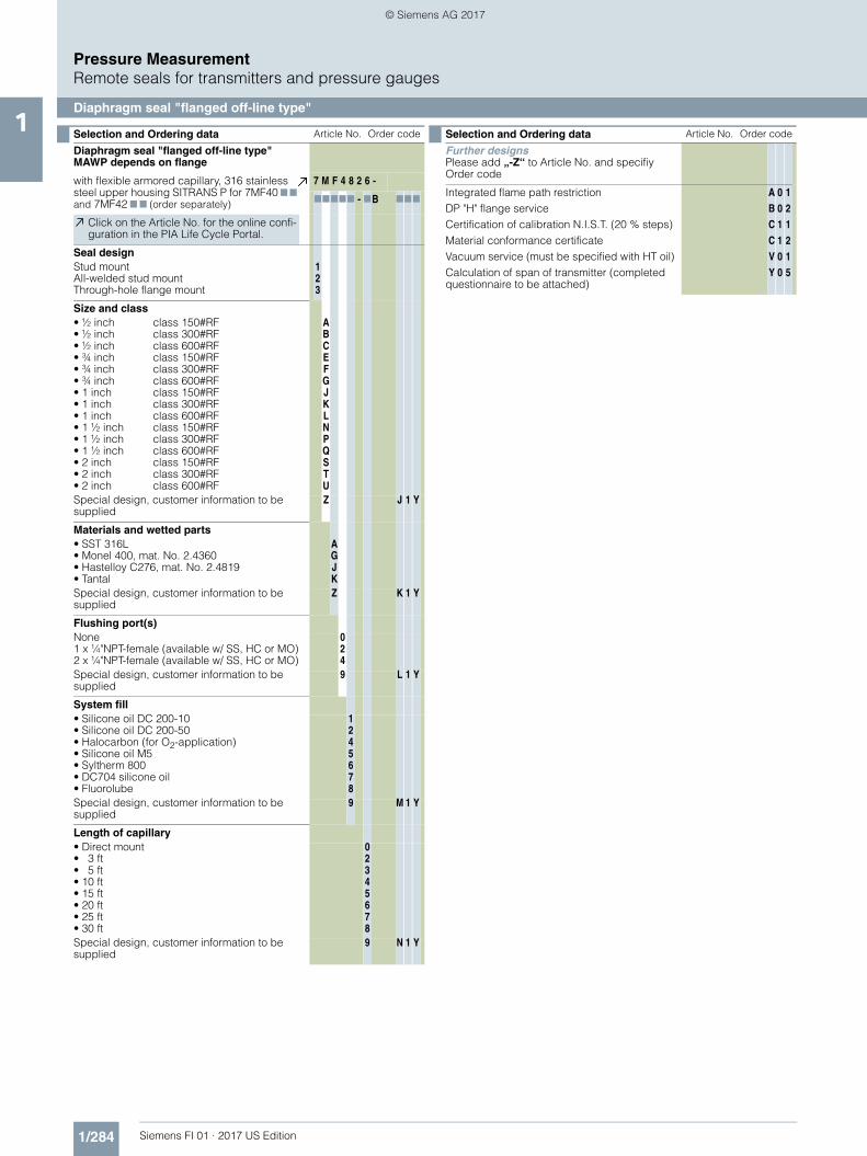
Selection and Ordering data Article No. Order code
Diaphragm seal "flanged off-line type" MAWP depends on flange
with flexible armored capillary, 316 stainless steel upper housing SITRANS P for 7MF40 7 7 and 7MF42 7 7 (order separately)
7 M F 4 8 2 6 -
77777 - 7B 777
Click on the Article No. for the online confi-guration in the PIA Life Cycle Portal.
Seal designStud mountAll-welded stud mountThrough-hole flange mount
123
Size and class• ½ inch• ½ inch• ½ inch• ¾ inch• ¾ inch• ¾ inch• 1 inch• 1 inch• 1 inch• 1 ½ inch• 1 ½ inch• 1 ½ inch• 2 inch• 2 inch• 2 inch
class 150#RFclass 300#RFclass 600#RFclass 150#RFclass 300#RFclass 600#RFclass 150#RFclass 300#RFclass 600#RFclass 150#RFclass 300#RFclass 600#RFclass 150#RFclass 300#RFclass 600#RF
ABCEFGJKLNPQSTU
Special design, customer information to be supplied
Z J 1 Y
Materials and wetted parts• SST 316L• Monel 400, mat. No. 2.4360• Hastelloy C276, mat. No. 2.4819• Tantal
AGJK
Special design, customer information to be supplied
Z K 1 Y
Flushing port(s)None1 x ¼"NPT-female (available w/ SS, HC or MO)2 x ¼"NPT-female (available w/ SS, HC or MO)
024
Special design, customer information to be supplied
9 L 1 Y
System fill• Silicone oil DC 200-10• Silicone oil DC 200-50• Halocarbon (for O2-application)• Silicone oil M5• Syltherm 800• DC704 silicone oil• Fluorolube
1245678
Special design, customer information to be supplied
9 M 1 Y
Length of capillary• Direct mount • 3 ft• 5 ft• 10 ft• 15 ft• 20 ft• 25 ft• 30 ft
02345678
Special design, customer information to be supplied
9 N 1 Y
Further designsPlease add „-Z“ to Article No. and specifiy Order code
Integrated flame path restrictionDP "H" flange serviceCertification of calibration N.I.S.T. (20 % steps)Material conformance certificateVacuum service (must be specified with HT oil)Calculation of span of transmitter (completed questionnaire to be attached)
A
B
C
C
V
Y
0
0
1
1
0
0
1
2
1
2
1
5
Selection and Ordering data Article No. Order code
FI01_2017_us_kap01.book Seite 284 Dienstag, 8. August 2017 10:06 10
© Siemens AG 2017

1/285Siemens FI 01 · 2017 US Edition
Pressure MeasurementRemote seals for transmitters and pressure gauges
Diaphragm seal "flanged off-line low-pressure type"1
■ Overview
Diaphragm seal "flanged off-line low-pressure type"
■ Dimensions (Connection to ASME B16.5)
Diaphragm seal "flanged off-line low-pressure type", dimensions
Instrument connection optionswelded capillary connection1/4” NPT1/2“ NPT
G2 G3 X A B C DM ESize Class½" 150# ½"-13UNC 4 5.91
5.91
0.06
3.5
2.36½" 300# ½"-13UNC 4 5.91 0.06 2.36½" 600# ½"-13UNC 4 5.91 0.25 2.55¾" 150# ½"-13UNC 4 5.91 0.06 2.36¾" 300# 5/8"-11UNC 4 5.91 0.06 2.36¾" 600# 5/8"-11UNC 4 5.91 0.25 2.551" 150# ½"-13UNC 4 5.91 0.06 2.361" 300# 5/8"-11UNC 4 5.91 0.06 2.361" 600# 5/8"-11UNC 4 5.91 0.25 2.55
1 ½" 150# ½"-13UNC 4 5.91 0.06 2.361 ½" 300# ¾"-10UNC 4 6.12 0.06 2.461 ½" 600# ¾"-10UNC 4 6.12 0.25 2.65
2" 150# 5/8"-11UNC 4 6.00 0.06 2.362" 300# 5/8"-11UNC 8 6.50 0.06 2.362" 600# 5/8"-11UNC 8 6.50 0.25 2.55
DM = Effective diaphragm diameterG2 = Process connectionG3 = Threaded bolt holeX = Number of bolt holesClass = Flange rating per ASME B16.5Size = Nominal pipe sizeAll dimensions in inches unless otherwise noted
FI01_2017_us_kap01.book Seite 285 Dienstag, 8. August 2017 10:06 10
© Siemens AG 2017
1/286 Siemens FI 01 · 2017 US Edition
Pressure MeasurementRemote seals for transmitters and pressure gauges
Diaphragm seal "flanged off-line low-pressure type"1
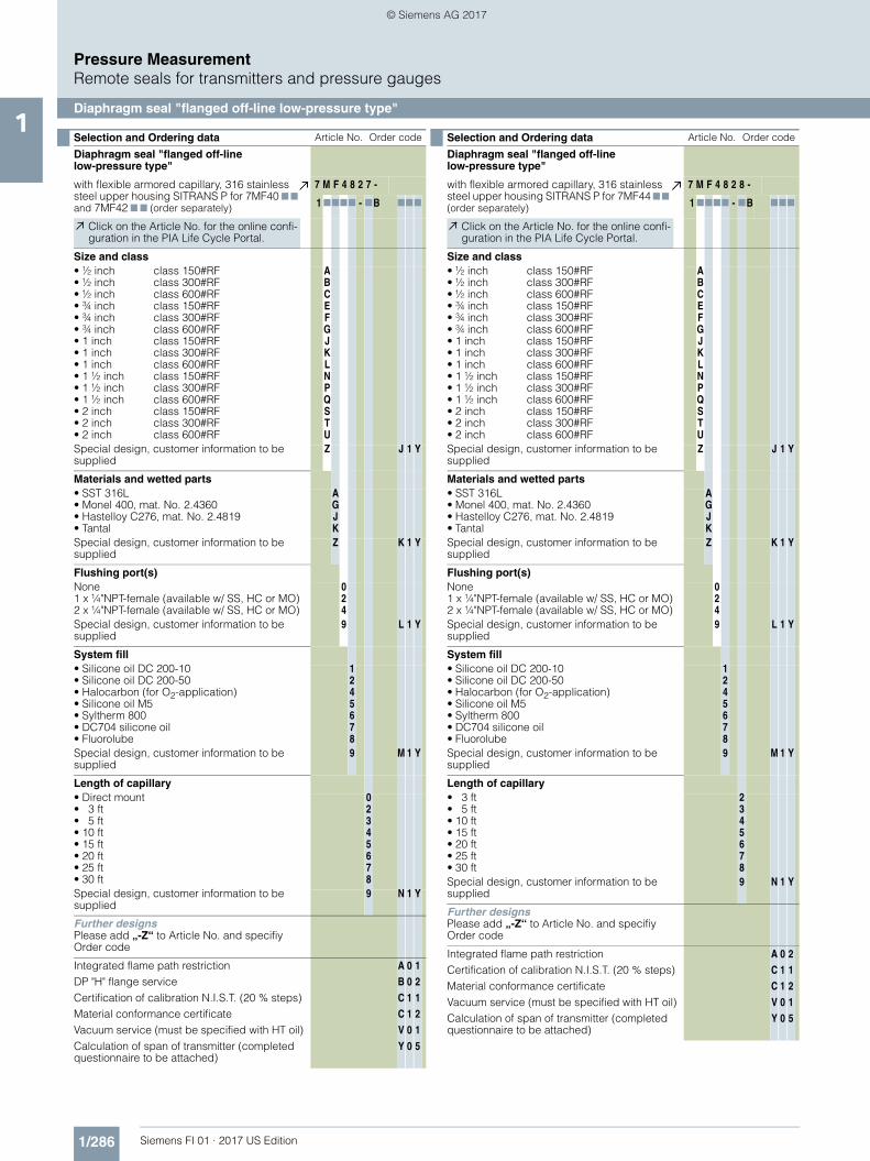
Selection and Ordering data Article No. Order code
Diaphragm seal "flanged off-line low-pressure type"
with flexible armored capillary, 316 stainless steel upper housing SITRANS P for 7MF40 7 7 and 7MF42 7 7 (order separately)
7 M F 4 8 2 7 -
1 7777 - 7B 777
Click on the Article No. for the online confi-guration in the PIA Life Cycle Portal.
Size and class• ½ inch• ½ inch• ½ inch• ¾ inch• ¾ inch• ¾ inch• 1 inch• 1 inch• 1 inch• 1 ½ inch• 1 ½ inch• 1 ½ inch• 2 inch• 2 inch• 2 inch
class 150#RFclass 300#RFclass 600#RFclass 150#RFclass 300#RFclass 600#RFclass 150#RFclass 300#RFclass 600#RFclass 150#RFclass 300#RFclass 600#RFclass 150#RFclass 300#RFclass 600#RF
ABCEFGJKLNPQSTU
Special design, customer information to be supplied
Z J 1 Y
Materials and wetted parts• SST 316L• Monel 400, mat. No. 2.4360• Hastelloy C276, mat. No. 2.4819• Tantal
AGJK
Special design, customer information to be supplied
Z K 1 Y
Flushing port(s)None1 x ¼"NPT-female (available w/ SS, HC or MO)2 x ¼"NPT-female (available w/ SS, HC or MO)
024
Special design, customer information to be supplied
9 L 1 Y
System fill• Silicone oil DC 200-10• Silicone oil DC 200-50• Halocarbon (for O2-application)• Silicone oil M5• Syltherm 800• DC704 silicone oil• Fluorolube
1245678
Special design, customer information to be supplied
9 M 1 Y
Length of capillary• Direct mount • 3 ft• 5 ft• 10 ft• 15 ft• 20 ft• 25 ft• 30 ft
02345678
Special design, customer information to be supplied
9 N 1 Y
Further designsPlease add „-Z“ to Article No. and specifiy Order code
Integrated flame path restrictionDP "H" flange serviceCertification of calibration N.I.S.T. (20 % steps)Material conformance certificateVacuum service (must be specified with HT oil)Calculation of span of transmitter (completed questionnaire to be attached)
A
B
C
C
V
Y
0
0
1
1
0
0
1
2
1
2
1
5
Selection and Ordering data Article No. Order code
Diaphragm seal "flanged off-line low-pressure type"
with flexible armored capillary, 316 stainless steel upper housing SITRANS P for 7MF44 7 7 (order separately)
7 M F 4 8 2 8 -
1 7777 - 7B 777
Click on the Article No. for the online confi-guration in the PIA Life Cycle Portal.
Size and class• ½ inch• ½ inch• ½ inch• ¾ inch• ¾ inch• ¾ inch• 1 inch• 1 inch• 1 inch• 1 ½ inch• 1 ½ inch• 1 ½ inch• 2 inch• 2 inch• 2 inch
class 150#RFclass 300#RFclass 600#RFclass 150#RFclass 300#RFclass 600#RFclass 150#RFclass 300#RFclass 600#RFclass 150#RFclass 300#RFclass 600#RFclass 150#RFclass 300#RFclass 600#RF
ABCEFGJKLNPQSTU
Special design, customer information to be supplied
Z J 1 Y
Materials and wetted parts• SST 316L• Monel 400, mat. No. 2.4360• Hastelloy C276, mat. No. 2.4819• Tantal
AGJK
Special design, customer information to be supplied
Z K 1 Y
Flushing port(s)None1 x ¼"NPT-female (available w/ SS, HC or MO)2 x ¼"NPT-female (available w/ SS, HC or MO)
024
Special design, customer information to be supplied
9 L 1 Y
System fill• Silicone oil DC 200-10• Silicone oil DC 200-50• Halocarbon (for O2-application)• Silicone oil M5• Syltherm 800• DC704 silicone oil• Fluorolube
1245678
Special design, customer information to be supplied
9 M 1 Y
Length of capillary• 3 ft• 5 ft• 10 ft• 15 ft• 20 ft• 25 ft• 30 ft
2345678
Special design, customer information to be supplied
9 N 1 Y
Further designsPlease add „-Z“ to Article No. and specifiy Order code
Integrated flame path restrictionCertification of calibration N.I.S.T. (20 % steps)Material conformance certificateVacuum service (must be specified with HT oil)Calculation of span of transmitter (completed questionnaire to be attached)
A
C
C
V
Y
0
1
1
0
0
2
1
2
1
5
FI01_2017_us_kap01.book Seite 286 Dienstag, 8. August 2017 10:06 10
© Siemens AG 2017

1/287Siemens FI 01 · 2017 US Edition
Pressure MeasurementRemote seals for transmitters and pressure gauges
Flushing rings1
■ Overview
Flushing ring
Flushing rings are required for flange-mounted and pancake type remote seals (Article No. 7MF4800 ... 7MF4823) if the dan-ger exists that the process conditions and the geometry of the connection could cause the process to form deposits or block-ages.
The flushing ring is clamped between the process flange and the remote seal.
Deposits can be flushed away from the diaphragm through the holes in the side, or the pressure volume can be vented. Different nominal diameters and forms permit adaptation to the respec-tive process flange.
Process connection
For flanges to EN and ASME:DN 50, 80, 100, 125; PN 16 ... 100 orDN 2 inch, 3 inch, 4 inch, 5 inch; Class 150 ... 600
Standard design
Material: CrNi-Stahl, mat. No. 1.4404/316LSealing faces and flushing holes: See Ordering data
■ Design
Installation example
■ Technical specifications
■ Dimensional drawings
Connection to EN 1092-1
Connection to ASME B 16.5
Flushing ring, dimension drawing
Flushing ring
Measuringpoint flange
Flushing outlet
Remote seal flange
Gasket
Flushing inlet
Flushing ring for remote seals of pancake and flange design
Nom. diam. Nom. press.• DN 50 PN 16 ... PN 100• DN 80 PN 16 ... PN 100• DN 100 PN 16 ... PN 100• DN 125 PN 16 ... PN 100
• 2 inch Class 150 ... class 600• 3 inch Class 150 ... class 600• 4 inch Class 150 ... class 600• 5 inch Class 150 ... class 600
Sealing face
• To EN 1092-1 Form B1Form B2Form D/Form DForm C/Form CForm C/Form CForm EForm F
• To ASME B16.5 RF 125 ... 250 AA RFSFRJT ring groove
Flushing holes (2 off), female thread:
• G¼• G½
• ¼-18 NPT
• ½-14 NPT
Material Stainless steel 1.4404/316L
DN PN d4 di h Weight
(mm) (bar) (mm) (mm) (mm) (kg)
50 16 ... 100 102 62 30 1.10
80 16 ... 100 138 92 30 1.90
100 16 ... 100 162 92 30 3.15
125 16 ... 100 188 126 30 3.50
DN Class d4 di h Weight
inch mm (inch) mm (inch) mm (inch) kg (lb)
2 150 ... 600 92 (3.62) 62 (2.44) 30 (1.18) 0.60 (1.32)
3 150 ... 600 127 (5) 92 (3.62) 30 (1.18) 1.05 (2.31)
4 150 ... 600 157 (6.18) 92 (3.62) 30 (1.18) 2.85 (6.28)
5 150 ... 600 185.5 (7.3) 126 (4.96) 30 (1.18) 3.30 (7.28)
Thre
addi
h
d4
FI01_2017_us_kap01.book Seite 287 Dienstag, 8. August 2017 10:06 10
© Siemens AG 2017

1/288 Siemens FI 01 · 2017 US Edition
Pressure MeasurementRemote seals for transmitters and pressure gauges
Flushing rings1
Selection and Ordering data Article No. Ord. code
Flushing ring 7 M F 4 8 2 5 -
for remote seals 7MF4900 to 7MF4923 1 7777 777
Click on the Article No. for the online configu-ration in the PIA Life Cycle Portal.
Nom. diam. Nom. press.
• 2 inch Class 150 ... 600 G• 3 inch Class 150 ... 600 H• 4 inch Class 150 ... 600 J• 5 inch Class 150 ... 600 K
Other versionAdd Order code and plain text:Nominal diameter: ...; Nominal pressure: ...
Z J 1 Y
Sealing face• ASME B16.5
- RF 125 ... 250 AA M- RFSF Q- RJT ring groove R
Other versionAdd Order code and plain text:Sealing face: ...
Z K 1 Y
Flushing holes (2 off)• Female thread G¼ 1• Female thread G½ 2• Female thread ¼-18 NPT 3• Female thread ½-14 NPT 4
Material• Stainless steel 316L 0Other versionAdd Order code and plain text:Material: ...
9 M 1 Y
Further designsPlease add „-Z“ to Article No. and specifiy Order code
Acceptance test certificate Bto EN 10204, section 3.1.B C 1 2
FI01_2017_us_kap01.book Seite 288 Dienstag, 8. August 2017 10:06 10
© Siemens AG 2017

1/289Siemens FI 01 · 2017 US Edition
Pressure MeasurementRemote seals for transmitters and pressure gauges
Diaphragm seal with quick connection1
■ Overview
Diaphragm seal with quick connection, with slotted union nut
■ Dimensions (connection to ASME B16.5)
Diaphragm seal with quick connection, with slotted union nut
Diaphragm seal with quick connection, with male thread, dimensions
■ Overview
Diaphragm seal with quick connection, Tri-Clamp connection
■ Dimensions (connection to ASME B16.5)
Diaphragm seal with quick connection, Tri-Clamp connection, dimen-sions
DN[mm]
MAWP[psi]
A[mm]
B C DM E G1 Weight[lbs]
25 600 Rd 52 x 1/6 2.48 0.83 1.0 2.36¼"-NPT
or½"-NPT female
1.332 600 Rd 58 x 1/6 2.76 0.83 1.3 2.72 1.640 600 Rd 65 x 1/6 3.07 0.83 1.6 2.17 2.550 360 Rd 78 x 1/6 3.62 0.87 2.1 2.32 2.8
DN[mm]
MAWP[psi]
A[mm]
B C DM E G1 Weight[lbs]
40 600 Rd 65 x 1/6 3.07 1.12 1.6 2.17 ¼"-NPTor
½"-NPT female
2.850 360 Rd 78 x 1/6 3.62 1.42 2.1 2.24 3.0
DM = Effective diaphragm diameterMAWP = Maximum Working Pressure @ 250 °FG1 = Instrument connectionDN = Nominal pipe sizeAll dimensions in inches unless otherwise noted
Type 7MF4840with union nut
Type 7MF4840with malethread
Size[in]
MAWP[psi]
A B C DM E G1 Weight[lbs]
1.5 600 1.50 1.97 1.71 1.0
1.38
¼"-NPTor
½"-NPT female
1.32 550 1.50 2.52 2.22 1.6 1.7
2.5 450 2.52 3.05 2.78 2.0 2.03 350 2.31 3.58 3.28 2.8 2.44 250 2.31 4.68 4.34 3.5 2.7
DM = Effective diaphragm diameterMAWP = Maximum Working Pressure @ 250 °F, higher rating with appropriate clamping deviceG1 = Instrument connectionSize = Nominal pipe sizeAll dimensions in inches unless otherwise noted
FI01_2017_us_kap01.book Seite 289 Dienstag, 8. August 2017 10:06 10
© Siemens AG 2017

1/290 Siemens FI 01 · 2017 US Edition
Pressure MeasurementRemote seals for transmitters and pressure gauges
Inline diaphragm seal with quick connection1
■ Overview
Diaphragm seal with quick connection, "i"-line (Cherry Burrel - male)
■ Dimensions (connection to ASME B16.5)
Diaphragm seal with quick connection, "i"-line (Cherry Burrel - male), dimensions
Size[in]
MAWP[psi]
A B C DM E F G1 Weight[lbs]
1.5 500
1.42
1.18 2.00 1.3 1.74 1.38 ¼"-NPTor
½"-NPT female
1.32 450 1.18 2.64 1.8 2.24 1.44 1.73 350 1.30 3.87 2.8 3.30 1.59 2.4
DM = Effective diaphragm diameterMAWP = Maximum Working Pressure @ 250 °F, higher rating with appropriate clamping deviceG1 = Instrument connectionSize = Nominal pipe sizeAll dimensions in inches unless otherwise noted
Selection and Ordering data Article No. Order code
Diaphragm seal
with quick connection for gage pressure transmitter SITRANS P 7MF40 7 7 and 7MF42 7 7 (order separately)made of 316 SS
7 M F 4 8 4 0 -
77A 0 7 - 7B 777
Click on the Article No. for the online confi-guration in the PIA Life Cycle Portal.
Process connectionDIN 11 851 with slotted union nutDN 25/PN 40DN 32/PN 40DN 40/PN 40DN 50/PN 25DN 65/PN 25DN 80/PN 25
111111
BCDEFG
DIN 11 851 with screw necksDN 25/PN 40DN 32/PN 40DN 40/PN 40DN 50/PN 25DN 65/PN 25DN 80/PN 25
222222
BCDEFG
Tri-Clamp Connection1 ½" 600 psi2" 550 psi2 ½" 450 psi3" 350 psi
4444
LMNP
Varivent (Tuchenhagen)Size 25132Size 40150
55
CE
Sanitary (4" Tank Spud)2" extension6" extension
66
BD
"I"-Line (Cherry Burrell - male)1 ½" 500 psi2" 450 psi3" 350 psi
555
UVW
Special design, customer information to be supplied
9 Z+
HJ
11
YY
System fill• Vegetable oil• Glycerin/Water 86.5/13.5 %• Neobee M20• Mineral oil
1234
Special design, customer information to be supplied
9 M 1 Y
Length of capillary• Direct Mount• 3 ft• 5 ft• 10 ft• 15 ft• 20 ft• 25 ft• 30 ft
02345678
Special design, customer information to be supplied
9 N 1 Y
Further designsPlease add „-Z“ to Article No. and specifiy Order code
Certification of calibration N.I.S.T. (20 % steps)Material conformance certificateVacuum service (must be specified with vege-table oil)Calculation of span of transmitter (completed questionnaire to be attached)
C
C
V
Y
1
1
0
0
1
2
1
5
Tank Spud accessories
Sanitary Tank Spud Clamp (1 pc.) P 1 0Sanitary Tank Spud O-ring (1 pc.) P 1 1Sanitary Tank Spud Weldolet 2" extension (1 pc.)
P 1 2
Sanitary Tank Spud Weldolet 6" extension (1 pc.)
P 1 3
FI01_2017_us_kap01.book Seite 290 Dienstag, 8. August 2017 10:06 10
© Siemens AG 2017

1/291Siemens FI 01 · 2017 US Edition
Pressure MeasurementRemote seals for transmitters and pressure gauges
Inline diaphragm seal with quick connection1
Selection and Ordering data Article No. Order code
Diaphragm seal
with quick connection for differential trans-mitter SITRANS P 7MF44 7 7 (order separately) made of 316 SS
7 M F 4 8 4 3 -
77A 0 7 - 7B 777
Click on the Article No. for the online confi-guration in the PIA Life Cycle Portal.
Process connectionDIN 11 851 with slotted union nutDN 50/PN 25DN 65/PN 25DN 80/PN 25DIN 11 851 with screw necksDN 50/PN 25DN 65/PN 25DN 80/PN 25Tri-Clamp Connection2" 550 psi2 ½" 450 psi3" 350 psi4" 250 psi"I"-Line (Cherry Burrell - male)3" 350 psi4" 200 psiSanitary (4" Tank Spud)2" extension6" extension
111
222
4444
55
66
EFG
EFG
MNPQ
WX
BD
Special design, customer information to be supplied
9 Z+
HJ
11
YY
System fill• Vegetable oil• Glycerin/Water 86.5/13.5 %• Neobee M20• Mineral oil
1234
Special design, customer information to be supplied
9 M 1 Y
Length of capillary• 3 ft• 5 ft• 10 ft• 15 ft• 20 ft• 25 ft• 30 ft
2345678
Special design, customer information to be supplied
9 N 1 Y
Further designsPlease add „-Z“ to Article No. and specifiy Order code
Certification of calibration N.I.S.T. (20 % steps)Material conformance certificateVacuum service (must be specified with vege-table oil)Calculation of span of transmitter (completed questionnaire to be attached)
C
C
V
Y
1
1
0
0
1
2
3
5
Tank Spud accessoriesSanitary Tank Spud Clamp (1 pc., two required) P 1 0
Sanitary Tank Spud O-ring (1 pc., two required) P 1 1
Sanitary Tank Spud Weldolet 2" extension (1 pc., two required)
P 1 2
Sanitary Tank Spud Weldolet 6" extension (1 pc., two required)
P 1 3
FI01_2017_us_kap01.book Seite 291 Dienstag, 8. August 2017 10:06 10
© Siemens AG 2017

1/292 Siemens FI 01 · 2017 US Edition
Pressure MeasurementRemote seals for transmitters and pressure gauges
Inline diaphragm seal with quick connection1
■ Overview
Inline diaphragm seal with quick connector, DIN 11851 with thread
■ Dimensions (connection to ASME B16.5)
Inline diaphragm seal with quick connector, DIN 11851 with thread, dimensions
■ Overview
Inline diaphragm seal with quick connection, Tri-clamp
■ Dimensions (connection to ASME B16.5)
Inline diaphragm seal with quick connection, Tri-clamp, dimensions
DN[mm]
MAWP[psi]
A B C E G H J L MB
15 600 Rd34x1/8 1.10 1.57 0.71 0.12 0.16 0.47 4.1 0.6325 600 Rd52x1/6 1.50 2.05 1.18 0.14 0.28 0.55 5.0 1.0240 600 Rd65x1/6 2.17 2.56 1.65 0.14 0.28 0.55 6.3 1.5050 360 Rd78x1/6 2.68 3.07 2.13 0.14 0.28 0.55 6.7 1.9765 360 Rd95x1/6 3.35 3.74 2.80 0.14 0.31 0.63 7.2 2.6080 360 Rd110x1/4 4.33 4.33 3.35 0.14 0.31 0.79 7.2 3.19
100 360 Rd130x1/4 5.12 5.12 4.09 0.16 0.39 0.79 7.2 3.94MB = Internal diameterMAWP = Maximum Working Pressure @ 250 °F, higher rating with appropriate clamping deviceDN = Nominal pipe sizeAll dimensions in inches unless otherwise noted
Size MAWP[psi]
A B C E L MB
¾" 600 0.7 1.34 0.8 0.98 3.8 0.61" 600 1.4 1.97 1.7 1.97 4.5 1.0
1.5" 600 1.7 1.97 1.7 1.97 5.7 1.52" 550 2.2 2.50 2.2 2.50 6.1 1.9
2.5" 450 2.7 3.10 2.8 3.10 6.1 2.43" 350 3.2 3.60 3.3 3.60 6.1 2.9
3.5" 350 3.7 4.20 3.8 4.20 6.1 3.34" 250 4.3 4.70 4.3 4.70 6.1 3.8
MB = Internal diameterMAWP = Maximum Working Pressure @ 250 °F, higher rating with appropriate clamping deviceSize = Nominal pipe sizeAll dimensions in inches unless otherwise noted
FI01_2017_us_kap01.book Seite 292 Dienstag, 8. August 2017 10:06 10
© Siemens AG 2017
1/293Siemens FI 01 · 2017 US Edition
Pressure MeasurementRemote seals for transmitters and pressure gauges
Inline diaphragm seal with quick connection1
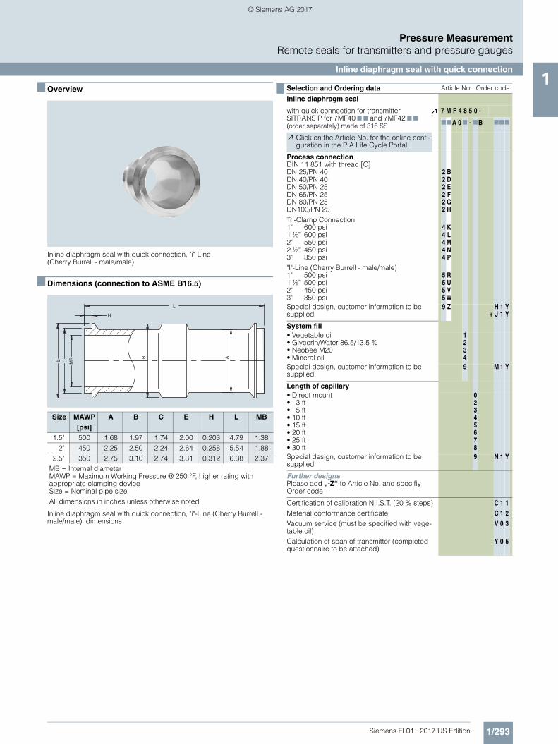
■ Overview
Inline diaphragm seal with quick connection, "i"-Line (Cherry Burrell - male/male)
■ Dimensions (connection to ASME B16.5)
Inline diaphragm seal with quick connection, "i"-Line (Cherry Burrell - male/male), dimensions
Size MAWP[psi]
A B C E H L MB
1.5" 500 1.68 1.97 1.74 2.00 0.203 4.79 1.382" 450 2.25 2.50 2.24 2.64 0.258 5.54 1.88
2.5" 350 2.75 3.10 2.74 3.31 0.312 6.38 2.37MB = Internal diameterMAWP = Maximum Working Pressure @ 250 °F, higher rating with appropriate clamping deviceSize = Nominal pipe sizeAll dimensions in inches unless otherwise noted
Selection and Ordering data Article No. Order code
Inline diaphragm seal
with quick connection for transmitter SITRANS P for 7MF40 7 7 and 7MF42 7 7(order separately) made of 316 SS
7 M F 4 8 5 0 -
77A 0 7 - 7B 777
Click on the Article No. for the online confi-guration in the PIA Life Cycle Portal.
Process connectionDIN 11 851 with thread [C]DN 25/PN 40DN 40/PN 40DN 50/PN 25DN 65/PN 25DN 80/PN 25DN100/PN 25Tri-Clamp Connection1" 600 psi1 ½" 600 psi2" 550 psi2 ½" 450 psi3" 350 psi"I"-Line (Cherry Burrell - male/male)1" 500 psi1 ½" 500 psi2" 450 psi3" 350 psi
222222
44444
5555
BDEFGH
KLMNP
RUVW
Special design, customer information to be supplied
9 Z+
HJ
11
YY
System fill• Vegetable oil• Glycerin/Water 86.5/13.5 %• Neobee M20• Mineral oil
1234
Special design, customer information to be supplied
9 M 1 Y
Length of capillary• Direct mount• 3 ft• 5 ft• 10 ft• 15 ft• 20 ft• 25 ft• 30 ft
02345678
Special design, customer information to be supplied
9 N 1 Y
Further designsPlease add „-Z“ to Article No. and specifiy Order code
Certification of calibration N.I.S.T. (20 % steps)Material conformance certificateVacuum service (must be specified with vege-table oil)Calculation of span of transmitter (completed questionnaire to be attached)
C
C
V
Y
1
1
0
0
1
2
3
5
FI01_2017_us_kap01.book Seite 293 Dienstag, 8. August 2017 10:06 10
© Siemens AG 2017
1/294 Siemens FI 01 · 2017 US Edition
Pressure MeasurementRemote seals for transmitters and pressure gauges
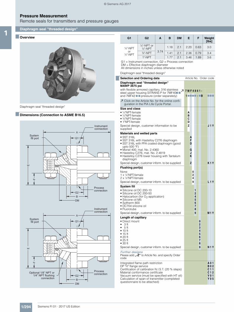
Diaphragm seal "threaded design"1
■ Overview
Diaphragm seal "threaded design"
■ Dimensions (Connection to ASME B16.5)
Diaphragm seal "threaded design"
Instrumentconnection
Instrumentconnection
Processconnection
Processconnection
Systemfill port
Systemfill port
Optional 1/8” NPT or1/4” NPT flushing
connection
G1 G2 A B DM E F Weight[lbs]
¼"-NPTor
½"-NPT
¼"-NPT or½"-NPT
3.741.18 2.1 2.20 0.63 3.0
¾"-NPT 1.41 2.1 2.36 0.79 3.41"-NPT 1.77 2.1 3.46 1.89 3.6
G1 = Instrument connection, G2 = Process connectionDM = Effective diaphragm diameterAll dimensions in inches unless otherwise noted
Selection and Ordering data Article No. Order code
Diaphragm seal "threaded design" MAWP 3675 psiwith flexible armored capillary, 316 stainless steel upper housing SITRANS P for 7MF407 7 and 7MF42 7 7 pressure (order separately)
7 M F 4 8 6 1 -
1 7777 - 7B 777
Click on the Article No. for the online confi-guration in the PIA Life Cycle Portal.
Size and class• ¼"NPT-female• ½"NPT-female• ¾"NPT-female• 1"NPT-female
ABCD
Special design, customer information to be supplied
Z J 1 Y
Materials and wetted parts• SST 316L• SST 316L with Hastelloy C276 diaphragm• SST 316L with PFA coated diaphragm (good
upto 500 °F)• Monel 400, mat. No. 2.4360• Hastelloy C276, mat. No. 2.4819• Hastelloy C276 lower housing with Tantalum
diaphragm
AFD
GJK
Special design, customer inform. to be supplied Z K 1 Y
Flushing port(s)None1 x ¼"NPT-female2 x ¼"NPT-female
024
Special design, customer inform. to be supplied 9 L 1 Y
System fill• Silicone oil DC 200-10• Silicone oil DC 200-50• Halocarbon (for O2-application)• Silicone oil M5• Syltherm 800• DC704 silicone oil• Fluorolube
1245678
Special design, customer inform. to be supplied 9 M 1 Y
Length of capillary• Direct mount• 3 ft• 5 ft• 10 ft• 15 ft• 20 ft• 25 ft• 30 ft
02345678
Special design, customer inform. to be supplied 9 N 1 Y
Further designsPlease add „-Z“ to Article No. and specify Order code
Integrated flame path restrictionDP "H" flange serviceCertification of calibration N.I.S.T. (20 % steps)Material conformance certificateVacuum service (must be specified with HT oil)Calculation of span of transmitter (completed questionnaire to be attached)
ABCCVY
001100
121215
FI01_2017_us_kap01.book Seite 294 Dienstag, 8. August 2017 10:06 10
© Siemens AG 2017

1/295Siemens FI 01 · 2017 US Edition
Pressure MeasurementRemote seals for transmitters and pressure gauges
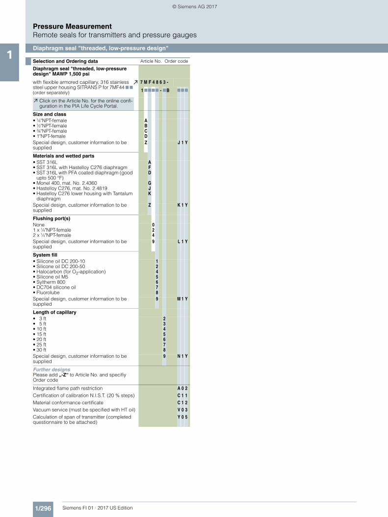
Diaphragm seal "threaded, low-pressure design"1
■ Overview
Diaphragm seal "threaded, low-pressure design"
■ Dimensions (Connection to ASME B16.5)
Diaphragm seal "threaded, low-pressure design, dimensions
G1 G2 A B C DM E F Weight[lbs]
¼"-NPTor
½"-NPT
¼"-NPT
5.91 4.92
1.25
3.5
3.00 0.90 14.0½"-NPT 1.25 3.00 0.90 14.0¾"-NPT 1.38 3.20 1.10 14.21"-NPT 1.75 3.50 1.40 14.5
G1 = Instrument connectionG2 = Process connectionDM = Effective diaphragm diameterAll dimensions in inches unless otherwise noted
Process connectionG2
CDM
FE
G1BA
Selection and Ordering data Article No. Order code
Diaphragm seal "threaded, low-pressure design" MAWP 1,500 psi
with flexible armored capillary, 316 stainless steel upper housing SITRANS P for 7MF407 7 and 7MF42 7 7 pressure (order separately)
7 M F 4 8 6 2 -
1 7777 - 7B 777
Click on the Article No. for the online confi-guration in the PIA Life Cycle Portal.
Size and class• ¼"NPT-female• ½"NPT-female• ¾"NPT-female• 1"NPT-female
ABCD
Special design, customer information to be supplied
Z J 1 Y
Materials and wetted parts• SST 316L• SST 316L with Hastelloy C276 diaphragm• SST 316L with PFA coated diaphragm• Monel 400, mat. No. 2.4360• Hastelloy C276, mat. No. 2.4819• Hastelloy C276 lower housing with Tantalum
diaphragm
AFDGJK
Special design, customer information to be supplied
Z K 1 Y
Flushing port(s)None1 x ¼"NPT-female2 x ¼"NPT-female
024
Special design, customer information to be supplied
9 L 1 Y
System fill• Silicone oil DC 200-10• Silicone oil DC 200-50• Halocarbon (for O2-application)• Silicone oil M5• Syltherm 800• DC704 silicone oil• Fluorolube
1245678
Special design, customer information to be supplied
9 M 1 Y
Length of capillary• Direct mount• 3 ft• 5 ft• 10 ft• 15 ft• 20 ft• 25 ft• 30 ft
02345678
Special design, customer information to be supplied
9 N 1 Y
Further designsPlease add „-Z“ to Article No. and specifiy Order code
Integrated flame path restrictionCertification of calibration N.I.S.T. (20 % steps)Material conformance certificateVacuum service (must be specified with HT oil)Calculation of span of transmitter (completed questionnaire to be attached)
A
C
C
V
Y
0
1
1
0
0
1
1
2
1
5
FI01_2017_us_kap01.book Seite 295 Dienstag, 8. August 2017 10:06 10
© Siemens AG 2017
1/296 Siemens FI 01 · 2017 US Edition
Pressure MeasurementRemote seals for transmitters and pressure gauges
Diaphragm seal "threaded, low-pressure design"1
Selection and Ordering data Article No. Order code
Diaphragm seal "threaded, low-pressure design" MAWP 1,500 psi
with flexible armored capillary, 316 stainless steel upper housing SITRANS P for 7MF44 7 7 (order separately)
7 M F 4 8 6 3 -
1 7777 - 7B 777
Click on the Article No. for the online confi-guration in the PIA Life Cycle Portal.
Size and class• ¼"NPT-female• ½"NPT-female• ¾"NPT-female• 1"NPT-female
ABCD
Special design, customer information to be supplied
Z J 1 Y
Materials and wetted parts• SST 316L• SST 316L with Hastelloy C276 diaphragm• SST 316L with PFA coated diaphragm (good
upto 500 °F)• Monel 400, mat. No. 2.4360• Hastelloy C276, mat. No. 2.4819• Hastelloy C276 lower housing with Tantalum
diaphragm
AFD
GJK
Special design, customer information to be supplied
Z K 1 Y
Flushing port(s)None1 x ¼"NPT-female2 x ¼"NPT-female
024
Special design, customer information to be supplied
9 L 1 Y
System fill• Silicone oil DC 200-10• Silicone oil DC 200-50• Halocarbon (for O2-application)• Silicone oil M5• Syltherm 800• DC704 silicone oil• Fluorolube
1245678
Special design, customer information to be supplied
9 M 1 Y
Length of capillary• 3 ft• 5 ft• 10 ft• 15 ft• 20 ft• 25 ft• 30 ft
2345678
Special design, customer information to be supplied
9 N 1 Y
Further designsPlease add „-Z“ to Article No. and specifiy Order code
Integrated flame path restrictionCertification of calibration N.I.S.T. (20 % steps)Material conformance certificateVacuum service (must be specified with HT oil)Calculation of span of transmitter (completed questionnaire to be attached)
A
C
C
V
Y
0
1
1
0
0
2
1
2
3
5
FI01_2017_us_kap01.book Seite 296 Dienstag, 8. August 2017 10:06 10
© Siemens AG 2017

1/297Siemens FI 01 · 2017 US Edition
Pressure MeasurementRemote seals for transmitters and pressure gauges
Inline diaphragm seal, wafer for pressure1
■ Overview
Inline diaphragm seal, wafer for pressure
■ Dimensions (Connection to ASME B16.5)
Inline diaphragm seal, wafer for pressure, dimensions
Size Class A MB L Weight[lbs]
1"
150# - 2500#
2.4 1.12
2.36
3.11.5" 3.3 1.69 4.8
2" 3.7 2.15 5.53" 5.1 3.25 8.84" 5.9 4.21 10.35" 7.3 5.20 15.06" 8.5 6.26 20.9
MB = Effective internal diameterClass = Flange rating per ASME B16.5Size = Nominal pipe sizeAll dimensions in inches unless otherwise noted
Optional instruments connectionswelded capillary connection1/4” NPT1/2” NPT
Selection and Ordering data Article No. Order code
Inline diaphragm seals wafer assembled to
SITRANS P for 7MF40 7 7 and 7MF42 7 7 (order separately)
7 M F 4 8 8 0 -
1 77 0 7 - 7B 777
Click on the Article No. for the online confi-guration in the PIA Life Cycle Portal.
Size and class• 1 inch• 1 ½ inch• 2 inch• 3 inch• 4 inch
class 150 to 2500class 150 to 2500class 150 to 2500class 150 to 2500class 150 to 2500
LMNPQ
Special design, customer information to be supplied
Z J 1 Y
Materials and wetted parts• SST 316L• SST 316L with PFA-Coating
(good up to 500 °F)• Monel 400, mat. No. 2.4360• Hastelloy C276, mat. No. 2.4819• Tantal
AD
GJK
Special design, customer information to be supplied
Z K 1 Y
System fill• Silicone oil DC 200-10• Silicone oil DC 200-50• Halocarbon (for O2-application)• Silicone oil M5• DC704 silicone oil• Fluorolube
124578
Special design, customer information to be supplied
9 M 1 Y
Length of capillary• Direct mount• 3 ft• 5 ft• 10 ft• 15 ft• 20 ft• 25 ft• 30 ft
02345678
Special design, customer information to be supplied
9 N 1 Y
Further designsPlease add „-Z“ to Article No. and specifiy Order code
Integrated flame path restrictionCertification of calibration N.I.S.T. (20 % steps)Material conformance certificateVacuum service (must be specified with HT oil)Calculation of span of transmitter (completed questionnaire to be attached)
A
C
C
V
Y
0
1
1
0
0
1
1
2
1
5
FI01_2017_us_kap01.book Seite 297 Dienstag, 8. August 2017 10:06 10
© Siemens AG 2017

1/298 Siemens FI 01 · 2017 US Edition
Pressure MeasurementRemote seals for transmitters and pressure gauges
Inline diaphragm seal, wafer for pressure1
Selection and Ordering data Article No. Order code
Inline diaphragm seals wafer assembled to
SITRANS P for 7MF44 7 7 (order separately) 7 M F 4 8 8 3 -
Click on the Article No. for the online confi-guration in the PIA Life Cycle Portal.
1 77 0 7 - 7B 777
Size and class• 1 inch• 1 ½ inch• 2 inch• 3 inch• 4 inch
class 150 to 2500class 150 to 2500class 150 to 2500class 150 to 2500class 150 to 2500
LMNPQ
Special design, customer information to be supplied
Z J 1 Y
Materials and wetted parts• SST 316L• SST 316L with PFA-Coating (good up to
500 °F)• Monel 400, mat. No. 2.4360• Hastelloy C276, mat. No. 2.4819• Tantal
ADGJK
Special design, customer information to be supplied
Z K 1 Y
System fill• Silicone oil DC 200-10• Silicone oil DC 200-50• Halocarbon (for O2-application)• Silicone oil M5• DC704 silicone oil• Fluorolube
124578
Special design, customer information to be supplied
9 M 1 Y
Length of capillary• 3 ft• 5 ft• 10 ft• 15 ft• 20 ft• 25 ft• 30 ft
2345678
Special design, customer information to be supplied
9 N 1 Y
Further designsPlease add „-Z“ to Article No. and specifiy Order code
Integrated flame path restrictionCertification of calibration N.I.S.T. (20 % steps)Material conformance certificateVacuum service (must be specified with HT oil)Calculation of span of transmitter (completed questionnaire to be attached)
A
C
C
V
Y
0
1
1
0
0
2
1
2
3
5
FI01_2017_us_kap01.book Seite 298 Dienstag, 8. August 2017 10:06 10
© Siemens AG 2017

1/299Siemens FI 01 · 2017 US Edition
Pressure MeasurementRemote seals for transmitters and pressure gauges
Diaphragm seal, saddle1
■ Overview
Diaphragm seal, saddle
■ Dimensions (Connection to ASME B16.5)
Diaphragm seal, saddle, dimensions
Radius To fit Pipe G1R Pipe size O.D.
1.49 2.5 3.00
¼"-NPTor
½"-NPT female
1.77 3.0 3.502.24 4.0 4.502.76 5.0 5.503.35 6.0 6.63
4.311 8.0 8.6255.374 10.0 10.756.378 12.0 12.75
7.0 14.0 14.75G1 = Instrument connectionAll dimensions in inches unless otherwise noted
Clamp ring
Spacer ring Upper housing
Adapter
GTAW
Saddle flange
FI01_2017_us_kap01.book Seite 299 Dienstag, 8. August 2017 10:06 10
© Siemens AG 2017

1/300 Siemens FI 01 · 2017 US Edition
Pressure MeasurementRemote seals for transmitters and pressure gauges
Diaphragm seal, saddle1
Selection and Ordering data Article No. Order code
Diaphragm seal, saddle, MAWP 1,500 psi
with flexible armored capillary or direct mount, 316 stainless steel upper housing and assemply hardware SITRANS P for 7MF40 7 7 or 7MF42 7 7 (order separately)
7 M F 4 8 9 0 -
1 7777 - 7B 777
Click on the Article No. for the online confi-guration in the PIA Life Cycle Portal.
Nominal pipe size• Not applicable
(Retrofit for existing 7MF48 7 7)• 2.5"• 3"• 4"• 5"• 6"• 8"• Retrofit 3" Conoflow (6 bolt pattern)• Retrofit 3" M&G style (8 bolt pattern)• Retrofit 4" Conoflow (6 bolt pattern)• Retrofit 4" M&G style (8 bolt pattern)
N
ABCDEGPQRS
Special design, customer information to be supplied
Z J 1 Y
Diaphragm material• SST 316L• SST 316L with PFA coated diaphragm (good
upto 500 °F)• Monel 400, mat. No. 2.4360• Hastelloy C276, mat. No. 2.4819• Tantal
AD
GJK
Special design, customer information to be supplied
Z K 1 Y
Saddle MaterialNone (Retrofit order)Carbon steel, Ni platedSST 316LHastelloy C276, mat. No. 2.4819
0124
Special design, customer information to be supplied
9 L 1 Y
System fill• Silicone oil DC 200-10• Silicone oil DC 200-50• Halocarbon (for O2-application)• Silicone oil M5• DC704 silicone oil• Fluorolube
124578
Special design, customer information to be supplied
9 M 1 Y
Length of capillary• Direct mount• 3 ft• 5 ft• 10 ft• 15 ft• 20 ft• 25 ft• 30 ft
02345678
Special design, customer information to be supplied
9 N 1 Y
Further designsPlease add „-Z“ to Article No. and specifiy Order code
Integrated flame path restrictionCertification of calibration N.I.S.T. (20 % steps)Material conformance certificateVacuum service (must be specified with HT oil)Calculation of span of transmitter (completed questionnaire to be attached)
A
C
C
V
Y
0
1
1
0
0
1
1
2
1
5
FI01_2017_us_kap01.book Seite 300 Dienstag, 8. August 2017 10:06 10
© Siemens AG 2017
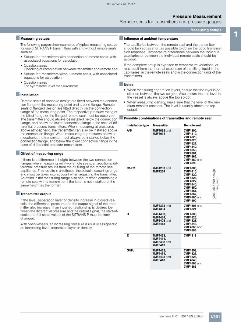
1/301Siemens FI 01 · 2017 US Edition
Pressure MeasurementRemote seals for transmitters and pressure gauges
Measuring setups1
■ Measuring setups
The following pages show examples of typical measuring setups for use of SITRANS P transmitters with and without remote seals, such as:• Setups for transmitters with connection of remote seals, with
associated equations for calculation.• Questionnaires
Checking of combination between transmitter and remote seal• Setups for transmitters without remote seals, with associated
equations for calculation• Questionnaires
For hydrostatic level measurements
■ Installation
Remote seals of pancake design are fitted between the connec-tion flange of the measuring point and a blind flange. Remote seals of flanged design are fitted directly on the connection flange of the measuring point. The respective pressure rating of the blind flange or the flanged remote seal must be observed. The transmitter should always be installed below the connection flange, and below the lower connection flange in the case of dif-ferential pressure transmitters. When measuring at pressures above atmospheric, the transmitter can also be installed above the connection flange. When measuring at pressures below at-mospheric, the transmitter must always be installed below the connection flange, and below the lower connection flange in the case of differential pressure transmitters.
■ Offset of measuring range
If there is a difference in height between the two connection flanges when measuring with two remote seals, an additional dif-ferential pressure results from the oil filling of the remote seal capillaries. This results in an offset of the actual measuring range and must be taken into account when adjusting the transmitter. An offset in the measuring range also occurs when combining a remote seal with a transmitter if the latter is not installed at the same height as the former.
■ Transmitter output
If the level, separation layer or density increase in closed ves-sels, the differential pressure and the output signal of the trans-mitter also increase. If an inverted relationship is desired be-tween the differential pressure and the output signal, the start-of-scale and full-scale values of the SITRANS P must be inter-changed.
With open vessels, an increasing pressure is usually assigned to an increasing level, separation layer or density.
■ Influence of ambient temperature
The capillaries between the remote seal and the transmitter should be kept as short as possible to obtain the good transmis-sion response. Temperature differences between the individual capillaries or between the individual remote seals should be avoided.
If the complete setup is exposed to temperature variations, er-rors result from the thermal expansion of the filling liquid in the capillaries, in the remote seals and in the connection units of the transmitters.
■ Notes
• When measuring separation layers, ensure that the layer is po-sitioned between the two spigots. Also ensure that the level in the vessel is always above the top spigot.
• When measuring density, make sure that the level of the me-dium remains constant. The level is usually above the top spigot.
■ Possible combinations of transmitter and remote seal
Installation type Transmitter Remote seal
A/B 7MF4033 and7MF4034
7MF4800,7MF4810,7MF4820,7MF4826,7MF4827,7MF4840,7MF4850,7MF4861,7MF4862,7MF4880 and7MF4890
C1/C2 7MF4233 and7MF4234
7MF4800,7MF4810,7MF4820,7MF4826,7MF4827,7MF4840,7MF4850,7MF4861,7MF4862,7MF4880 and7MF4890
(vac
uum
-pro
of d
esig
n re
qui
red
)
7MF4333 and7MF4334
7MF4801 and7MF4821
D 7MF4433,7MF4434,7MF5403 and7MF5413
7MF4803,7MF4823,7MF4828,7MF4843,7MF4863 and7MF4883
E 7MF4433,7MF4434,7MF5403 and7MF5413
7MF4813
G/H/J 7MF4433,7MF4434,7MF5403 and7MF5413
7MF4803,7MF4823,7MF4828,7MF4843,7MF4863 and7MF4883
FI01_2017_us_kap01.book Seite 301 Dienstag, 8. August 2017 10:06 10
© Siemens AG 2017

1/302 Siemens FI 01 · 2017 US Edition
Pressure MeasurementRemote seals for transmitters and pressure gauges
Measuring setups with remote seals1
■ Dimensional drawings
Types of installation for pressure and level measurements (open vessels)
Types of installation for absolute level measurements (closed vessels)
Type of installation for differential pressure and flow measurements
Installation type A
Start-of-scale: pMA = ρFL · g · HU - ρOil · g · H1
Full-scale: pME = ρFL · g · HO - ρOil · g · H1
Installation type B
Start-of-scale: pMA = ρFL · g · HU + ρOil · g · H1
Full-scale: pME = ρFL · g · HO + ρOil · g · H1
LegendpMA Start-of-scale value to be setpME Full-scale value to be setρFL Density of medium in vesselρOil Density of filling oil in the capillary to the remote
sealg Local acceleration due to gravityHU Start-of-scale valueHO Full-scale valueH1 Distance between vessel flange and pressure
trans.
Pressure transmitterabove the measuring point
Pressure transmitterbelow the measuring point
H1 ≤ 7 m (23 ft), with halocarbon oil as filling liquid only H1 ≤ 4 m (13.1 ft)
Installation type A Installation type B
H1
H1HU
∆H
HO
HU
∆HHO
Pressure transmitter for absolute pressure always below the measuring point: H1 ≥ 200 mm (7.9 inch)
Installation type C1 Installation type C2 Installation type C1 and C2
Start-of-scale: pMA = pSTART + ρOil · g · H1
Full-scale: pME = pEND + ρOil · g · H1
LegendpMA Start-of-scale value to be setpME Full-scale value to be setpSTART Start-of-scale valuepEND Full-scale valueρOil Density of filling oil in the capillary to
the remote sealg Local acceleration due to gravityH1 Distance between vessel flange and
pressure trans.
H1
pabs pabs
H1
Installation type D
Start-of-scale: pMA = pSTART - ρOil · g · HV
Full-scale: pME = pEND - ρOil · g · HV
LegendpMA Start-of-scale value to be setpME Full-scale value to be setpSTART Start-of-scale valuepEND Full-scale valueρOil Density of filling oil in the capillary
to the remote sealg Local acceleration due to gravityHV Distance between the measuring
points (spigots)
Installation type D Filter monitoring
H2
HVH1
+ -
FI01_2017_us_kap01.book Seite 302 Dienstag, 8. August 2017 10:06 10
© Siemens AG 2017
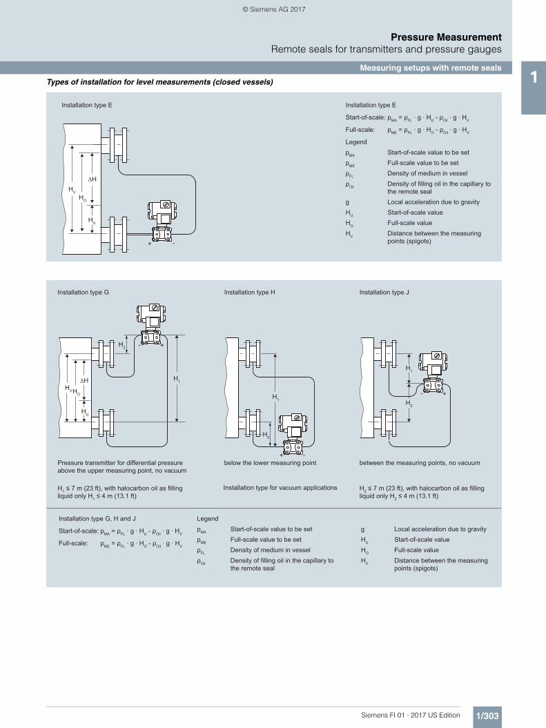
1/303Siemens FI 01 · 2017 US Edition
Pressure MeasurementRemote seals for transmitters and pressure gauges
Measuring setups with remote seals1Types of installation for level measurements (closed vessels)
Installation type E
Start-of-scale: pMA = ρFL · g · HU - ρOil · g · HV
Full-scale: pME = ρFL · g · HO - ρOil · g · HV
LegendpMA Start-of-scale value to be setpME Full-scale value to be setρFL Density of medium in vesselρOil Density of filling oil in the capillary to
the remote sealg Local acceleration due to gravityHU Start-of-scale valueHO Full-scale valueHV Distance between the measuring
points (spigots)
Installation type E
HO
HV
∆H
HU
+ -
Installation type JInstallation type HInstallation type G
between the measuring points, no vacuumbelow the lower measuring pointPressure transmitter for differential pressureabove the upper measuring point, no vacuum
H1 ≤ 7 m (23 ft), with halocarbon oil as filling liquid only H1 ≤ 4 m (13.1 ft)
H2 ≤ 7 m (23 ft), with halocarbon oil as filling liquid only H2 ≤ 4 m (13.1 ft)
g Local acceleration due to gravityHU Start-of-scale valueHO Full-scale valueHV Distance between the measuring
points (spigots)
LegendpMA Start-of-scale value to be setpME Full-scale value to be setρFL Density of medium in vesselρOil Density of filling oil in the capillary to
the remote seal
Installation type G, H and J
Start-of-scale: pMA = ρFL · g · HU - ρOil · g · HV
Full-scale: pME = ρFL · g · HO - ρOil · g · HV
Installation type for vacuum applications
HU
∆HHO
HV
H2
H1
+-
-+
+-H1
H2
H1
H2
FI01_2017_us_kap01.book Seite 303 Dienstag, 8. August 2017 10:06 10
© Siemens AG 2017
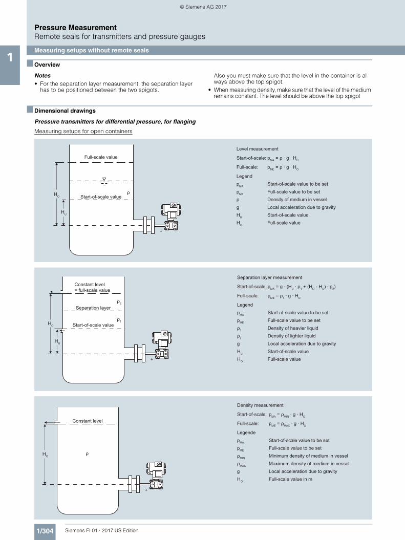
1/304 Siemens FI 01 · 2017 US Edition
Pressure MeasurementRemote seals for transmitters and pressure gauges
Measuring setups without remote seals1
■ Overview
Notes• For the separation layer measurement, the separation layer
has to be positioned between the two spigots.
Also you must make sure that the level in the container is al-ways above the top spigot.
• When measuring density, make sure that the level of the medium remains constant. The level should be above the top spigot
■ Dimensional drawings
Pressure transmitters for differential pressure, for flanging
Measuring setups for open containers
Level measurement
Start-of-scale: pMA = ρ · g · HU
Full-scale: pME = ρ · g · HO
LegendpMA Start-of-scale value to be setpME Full-scale value to be setρ Density of medium in vesselg Local acceleration due to gravityHU Start-of-scale valueHO Full-scale value
Full-scale value
Start-of-scale value
+
ρHO
HU
Separation layer measurement
Start-of-scale: pMA = g · (HU · ρ1 + (HO - HU) · ρ2)
Full-scale: pME = ρ1 · g · HO
LegendpMA Start-of-scale value to be setpME Full-scale value to be setρ1 Density of heavier liquidρ2 Density of lighter liquidg Local acceleration due to gravityHU Start-of-scale valueHO Full-scale value
Constant level= full-scale value
Start-of-scale value
Separation layer
+
HO
HU
ρ1
ρ2
Constant level
Density measurement
Start-of-scale: pMA = ρMIN · g · HO
Full-scale: pME = ρMAX · g · HO
LegendepMA Start-of-scale value to be setpME Full-scale value to be setρMIN Minimum density of medium in vesselρMAX Maximum density of medium in vesselg Local acceleration due to gravityHO Full-scale value in m
+
HOρ
FI01_2017_us_kap01.book Seite 304 Dienstag, 8. August 2017 10:06 10
© Siemens AG 2017

1/305Siemens FI 01 · 2017 US Edition
Pressure MeasurementRemote seals for transmitters and pressure gauges
Measuring setups without remote seals1Measuring setups for closed containers
Level measurement, Version 1
Start-of-scale: ∆pMA = ρ · g · HU
Full-scale: ∆pME = ρ · g · HO
Legend∆pMA Start-of-scale value to be set∆pME Full-scale value to be setρ Density of medium in vesselg Local acceleration due to gravityHU Start-of-scale valueHO Full-scale value
Gas-filled negativepressure line
Transmitterreference line
Maximum level
Start-of-scale value
Full-scale value
Staticpressure
ρ
HO
HU
+ -
Constantreferencelevel
Level measurement, Version 2
Start-of-scale: ∆pMA = g · (HU · ρ - HV · ρ')
Full-scale: ∆pME = g · (HO · ρ - HV · ρ')
Legend∆pMA Start-of-scale value to be set∆pME Full-scale value to be setρ Density of medium in vesselρ' Density of liquid in the negative pressure
line (corresponding to the temperature existing there)
g Local acceleration due to gravityHU Start-of-scale valueHO Full-scale valueHV Distance between the measuring points
(spigots)
Liquid-filled negativepressure line
Transmitterreference line
Mamimum level
Start-of-scale value
Full-scale value
Staticpressure
ρ
ρ' HV
HU
+ -
HO
Separation layer measurement
Start-of-scale: ∆pMA = g · (HU · ρ1 + (HO - HU) · ρ2 - HV · ρ'2)
Full-scale: ∆pME = g · (HO · ρ1 - HV · ρ'2)
Legend∆pMA Start-of-scale value to be set∆pME Full-scale value to be setρ1 Density of heavier liquid with separation layer
in vesselρ2 Density of lighter liquid with separation layerρ'2 Density of liquid in the negative pressure line (corresponding to the temperature existing
there)g Local acceleration due to gravityHU Start-of-scale valueHO Full-scale valueHV Distance between the measuring points
(spigots)
Transmitterreference line
Static pressure
Constant level
Max. separation layer
Start-of-scale value
Full-scale value
Staticpressure
ρ'2 HVρ2
ρ1
HO
HU
+ -
FI01_2017_us_kap01.book Seite 305 Dienstag, 8. August 2017 10:06 10
© Siemens AG 2017