press tooling. em24.02.041 /b interface for fastening and ... for fastening and connecting specific...
TRANSCRIPT

© RENAULT 2002 Origin: PEGI - Renault Page: 1 / 21
Press tooling. Interface for fastening and connecting specific grippers on lines of MP, GP, and TGSE presses
EM24.02.041 /B ________________________________________
Standard ________________________________________
Status Enforceable
Importante Note : This document has been translated from the french. In the event of any dispute, only th french
version is referred to as the reference text and is binding on the parties. Object Standardise the fastening and connections between specific automation devices and
robots between presses. Scope of application Renault group Issued by 65307 - Stamping Process Industrialisation Confidentiality Non confidential Approved by Function Signature Application date
D.COURATIN Head of 65307 Department 12/2002
NOTE TO the USERS This document was technically validated again, in that state, by the department 65307 in 01/2008.

EM24.02.041 /B
© RENAULT 2002 Origin: PEGI - Renault Page: 2 / 21
History of versions
Version Update Object of main modifications Author A 11/2000 Creation (1) J.Gabillet Dept 65307 B 12/2002 Modifications or additions are indicated in the standard’s text
margin by a black vertical line. Added T beam, KR100 robot, MP scope, repair and universal destacker Removed the table "Robot gripper inputs" Removed KUKA robot abacus.
J.Gabillet Dept 65307
Supersedes same index of 11/2000 version A Availability Inside Renault, on the Intranet: http://gdxpegi.ava.tcr.renault.fr
Outside Renault, on the Internet: www.cnomo.com E.mail: [email protected]
Documents cited Regulations : International : European : French : CNOMO : Renault : EM24.02.043. Other internal doc : Other external doc : Coding ICS: 25.120.10 Class E24 Key words emboutissage, équipement de presse, préhenseur, automatisation, automation, pressing,
gripper, KUKA, ABB, robot, IRB 600, 6650, press equipment,
Language French (1) Have participated in writing the document Site Dept Name Site Dept Name DOUAI Dept. 32 D. MARIEZ GUYANCOUR
T 65304 D. MARCEL
FASA VAL DFCAR BERRIO SANCHEZ SANDOUVILLE 04737 P.GALEOTTI FASA PAL DIVD FERNANDEZ ORALLO FLINS 06534 J.M COUCHOURON

EM24.02.041 /B
© RENAULT 2002 Origin: PEGI - Renault Page: 3 / 21
Contents
Page
Foreword ..................................................................................................................................... 3 1 Robot TGSE interface functions ............................................................................................... 4 2 Description of equipment for Robot TGSE .............................................................................. 4 2.1 Robot side interface ......................................................................................................................................5 2.2 Equipment interface side specific TYPE A....................................................................................................6 2.3 Semi-capacity beam TYPE E........................................................................................................................7 2.4 Semi-capacity beam TYPE T ......................................................................................................................10 2.5 Maximum load capacity abacuses ..............................................................................................................13 3 GP robot interface functions ................................................................................................... 13 4 Description of equipment for GP Robot ................................................................................. 14 4.1 Assembled set.............................................................................................................................................14 4.2 Specific gripping elements of GP Robot .....................................................................................................14 5 Abacus....................................................................................................................................... 15 6 « Classical » GP interface functions....................................................................................... 17 6.1 Loader/extractor interface ...........................................................................................................................17 6.2 Shuttle interface ..........................................................................................................................................18 6.3 Flipper interface...........................................................................................................................................19 6.4 Capacities....................................................................................................................................................19 7 Non-robot TGSE interface functions ...................................................................................... 19 7.1 Loader/extractor interface ...........................................................................................................................20 7.2 Shuttle interface ..........................................................................................................................................20 7.3 Capacities....................................................................................................................................................20 8 MP interface functions ............................................................................................................. 21 9 Case out of standard ................................................................................................................ 21 10 Troubleshooting ....................................................................................................................... 21 11 List of documents cited ........................................................................................................... 21
Foreword The purpose of this standard is to ensure interchangeability of specific automation equipment (gripping) for very large simple effect lines (TGSE) and large presses (GP) over all Renault stamping sites.

EM24.02.041 /B
© RENAULT 2002 Origin: PEGI - Renault Page: 4 / 21
1 Robot TGSE interface functions The specific automation equipment:
are centred and fastened mechanically on the robot on an interface, receive, at most, 2 pneumatic commands, i.e. 4 fittings + end stop contacts, are changed by hand or in automatic.
In case of manual change, the specific gripping elements are changed on the semi-capacity beam which remains fixed on the robot. In case of assisted change (automatic or manual), the equipment is centred on a swivel stand used by the robot to lay the previous gripping then, take the new one according to the diagram below. Specific elements are changed manually on the beam type E located on the gate (preparation side).
Example of solution used (2000-2002):
2 Description of equipment for Robot TGSE There are 2 types of interfaces:
Beam type E, standard solution < year 2002, fitted on reorganised TGP (small opening), Beam type T, standard solution > year 2002, not retained on reorganised TGP.
Refer to department 65307 for confirmation of the solution fitted on line. The interface is fitted either on changer type A, manual or automatic version (see paragraph. 2.1) or directly on robot flange.
specific elementsswivel stand
Warning in theencastrement
SIDE ROBOTPREPARATION OF EQUIPMENTS SIDE
Rotation during the automatic load
semi capacitybeam
specific elementsswivel stand
Warning in theencastrement
SIDE ROBOTPREPARATION OF EQUIPMENTS SIDE
Rotation during the automatic load
semi capacitybeam

EM24.02.041 /B
© RENAULT 2002 Origin: PEGI - Renault Page: 5 / 21
2.1 Robot side interface Assembled set TYPE A Material: steel Manual fitting: the operator engages the specific stand then swivels the handle until it clicks. Automatic fitting: locking the specific stand is performed by the jack. Material: steel Weight: Manual version 4.1 kg (S) Automatic version 4.1 kg (S) 5.1 kg (R) 10 kg (R) Total 9.2 kg 14.1 kg S = Specific side (see paragraph 2.2) R = Robot side (see paragraph 2.1)
Square on end of line robot (before laying on conveyor, except VLL L9) In order to have several laying configurations on the 2 "Y" conveyors, a 90° bracket is used on the last robot (to be checked on ABB 6650 robot). The robot flange is oriented vertically. Material: steel Weight: 6 kg
REFERENCECHARGER
REFERENCE HEAD OF ROBOT
REF. FIXATIONOF THE SPECIFIC,TYPE A
MANUAL FUNCTION
AUTOMATIC FUNCTION
Axis 6
REFERENCECHARGER
REFERENCE HEAD OF ROBOT
REF. FIXATIONOF THE SPECIFIC,TYPE A
MANUAL FUNCTION
AUTOMATIC FUNCTION
Axis 6

EM24.02.041 /B
© RENAULT 2002 Origin: PEGI - Renault Page: 6 / 21
2.2 Equipment interface side specific TYPE A
With type A, the gripper head assembly is positioned by a drawing , centred by a bore and oriented by an open pin ∅ 10g6 . Holes ∅ 13,5 are planned for 4 fastening screws (and "NORLOC" washers). The suction cups are connected by flexible hoses ∅ 6 x 8 on pneumatic circuits 1 and 2. There are 2 independent vacuum circuits:
Circuit 1: mark and .
Circuit 2: mark , and . Any pneumatic commands for swivelling, pushing parts (2 commands maximum) are connected with flexible hoses to the 2 + 2 fittings.
Control circuit 1 One way: connect to marker .
Control circuit 1 Back: connect to marker .
Control circuit 2 One way: connect to marker .
Control circuit 2 Back: connect to marker . The wiring must be connected to the A connector according to contact allocation. Robot grippers inputs Fitting location: Axis robot 3 terminal block XL25 Type of module: IBST 24 DI 32/2 Designation: +XL25-A2 General occupation of the gripper
Signal Gripper pin
Power supply 24 VDC 14
Power supply 0 VDC 15
REFERENCECHARGER
REF.OF SPECIFIC TYPE A
REFERENCECHARGER
REF.OF SPECIFIC TYPE A

EM24.02.041 /B
© RENAULT 2002 Origin: PEGI - Renault Page: 7 / 21
2.3 Semi-capacity beam TYPE E There are 2 versions of beam, different from the rear plate (fastening, centring):
no change, With change, manual or automatic version.
2.3.1 No beam change The beam remains on the robot and the operator changes specific elements. Material aluminium: weight: 10 kg (P) weight: 8 kg ( I ) Total 18 kg The beam is delivered without the aluminium block used for positioning on rotating door (solution with change).
2.3.2 With manual or automatic change The robot (automatic) or operator (manual) lays the beam with the specific elements on the stand (on swivel door in automatic version). The operator changes the specific elements on the stand, on equipment preparation side (marking with colours of the specific locations on the beam: red, yellow, blue). Material aluminium: weight: 11 kg (P) weight: 8 kg ( I ) Total 19 kg
Reference of the specificAxis 6 of robot
Detail of the specific interface
Specific
Reference of the specificAxis 6 of robot
Detail of the specific interface
Specific
holesholes
Fixation beam to adapt on axis 6 of the robot
view according to F
holes
holes
view according to F
Hole for installationon swivel stand
Fixation beam foreseen to adaptthe interface of type A
(Automatic)

EM24.02.041 /B
© RENAULT 2002 Origin: PEGI - Renault Page: 8 / 21
2.3.3 Case of the end line robot with bracket For the last robot (case of end of line in "Y") fitted with a 90° bracket, the version of the beam fastened directly onto the bracket is that "without change" (see paragraph. 2.3.1).
2.3.4 Pneumatic connections For this type of beam, there is a large diversity of connections related with the choice of equipment and/or number of venturis used on the robot. The inventory of 2001 is summarised below.
Upstream Interface Downstream
Venturi Arm Beam
Plant Nr/Type lines Qty Reference Number Type Nr Reference Type Connector Interface
Schmalz/SMP 15 V1 -
L 3 Schmalz/SMP 15 V2 -
VLL 5 Schmalz/SMP 15 V3 - B1 Bilsing ABB Manual
TGSE Rob KUKA Schmalz/SMP 15 V4 -
Schmalz/SMP 15 V5 -
Schmalz/SMP 15 V1 < B1/B2 AMG
L 9 Schmalz/SMP 15 V2 < B1/B2 AMG
VLL 5 Schmalz/SMP 15 V3 - B2 AMG E 2/4/2 Auto
TGSE Rob KUKA Schmalz/SMP 15 V4 < B2/B3 AMG
Schmalz/SMP 15 V5 - B3 AMG
L 2 Schmalz/SMP 25 V1 < B1 AMG
PAL 3 Schmalz/SMP 25 V2 < B2 AMG E 2/2/2 Auto
TGSE Rob KUKA Schmalz/SMP 25 V3 < B3 AMG
L 8 Coval V1 < B1 AMG
LHA 3 Coval V2 < B2 AMG E 2/2/2 without
TGSE Rob KUKA Coval V3 < B3 AMG
L 11 Coval V1 < B1 AMG
LHA 3 Coval V2 < B2 AMG E 2/2/2 without
TGSE Rob KUKA Coval V3 < B3 AMG
Schmalz/SMP 15 V1 < B2/B3 AMG
L 21 Schmalz/SMP 15 V2 - B1 AMG
UGB 5 Schmalz/SMP 15 V3 - B1 AMG E 2/2/2 Auto
TGSE Rob KUKA Schmalz/SMP 15 V4 - B2 AMG
Schmalz/SMP 15 V5 - B3 AMG
(see legends next page)

EM24.02.041 /B
© RENAULT 2002 Origin: PEGI - Renault Page: 9 / 21
Legends:
Type Specifies the pneumatic link between the automation venturis and arms.
Example: - direct connection between the venturi and the arm specified in the next column
< connection Y bypass between venturi and the 2 arms specified in the next column Arm AMG case see below, for Bilsing there is one arm only
B1 P O U
⇒ T
⇒
PRESS Progress direction B2 R Progress direction PRESS E A M OP extraction B3 G OP loading
Connector The digits correspond to the numbers of Staubli fitted on the AMG/Gripper beam interface (B1/B2/B3). Example: 2/4/2 means 2 staublis on the interface of Arm B1, 4 staublis on the interface of the Arm B2 and 2 staublis on the Arm B3 Refer to department 65307 for confirmation. Case of UGB: Receive 2 vacuum circuits distributed over, at most, 3 + 2 = 5 pneumatic fittings,
BLUE
YELLOW
RED
Pneumatic circuit 1
Pneumatic circuit 2 Specific elementsin every part
Manual or automaticclamping of the specific
BLUE
YELLOW
RED
Pneumatic circuit 1
Pneumatic circuit 2 Specific elementsin every part
Manual or automaticclamping of the specific

EM24.02.041 /B
© RENAULT 2002 Origin: PEGI - Renault Page: 10 / 21
2.4 Semi-capacity beam TYPE T
This type of beam is standard since 2002 and is used initially on TGSE L12 of UPL.
2.4.1 Technical definition The T beam is in woven carbon with aluminium inserts. Locking is ensured by cleats, the air intake by 2 stands (1 per ½ gripper) of 4 staublis. Weight alone: 12 kg KUKA reference: 819.002-10.025.02
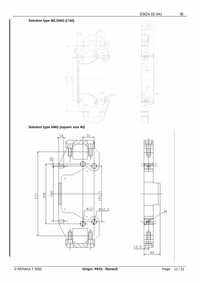
2.4.2 Specific link The three 1/2 specifics are fitted on the T beam using 2 callipers/grippers as defined in the next page. This interface is standard for its "fix on beam" function, but several types of equipment can be used (square or round cross-section). Two versions presented below are defined.
EM24.02.041 /B
© RENAULT 2002 Origin: PEGI - Renault Page: 11 / 21
Solution type BILSING (∅40)
Solution type AMG (square size 40)

EM24.02.041 /B
© RENAULT 2002 Origin: PEGI - Renault Page: 12 / 21
2.4.3 Derived case For destacking the new TGSE, a "universal" gripper is built into the destacking robot:
It is fitted on a carbon beam derived from the type of interpress. It is removable and a specific gripper can be fitted on this beam. It includes 18 suction cups piloted by physical contact on the blank. The geometry is frozen, but cannot adapt with existing or future ranges after study. It exists in square (AMG) or cylindrical (BILSING) versions. Suction is controlled by 18 valves and blowing by a 19th, micro-venturi are distributed on the
gripper. The following diagram is given for information. For more information, contact Department 65307.
This type of gripper is not generalised over all new TGSE lines (PAL L2/UGB L21, L18/LHA L11...) and those installed have all been modified to adapt them.
EM24.02.041 /B
© RENAULT 2002 Origin: PEGI - Renault Page: 13 / 21
2.5 Maximum load capacity abacuses 2.5.1 Load curves
The load curves and values of table represent the maximum load capacity. Exceeding this capacity reduces the life time of the robot and maximum rate of the line. The values thus determined are indispensable to define the robot’s scope of application. The values to calculate the robot’s maximum load, from axis 6, take into consideration the weight of elements fastened from this axis (interface, beam, specific elements, part, and others).
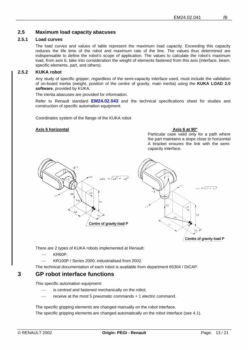
2.5.2 KUKA robot Any study of specific gripper, regardless of the semi-capacity interface used, must include the validation of on-board inertia (weight, position of the centre of gravity, main inertia) using the KUKA LOAD 2.0 software, provided by KUKA. The inertia abacuses are provided for information. Refer to Renault standard EM24.02.043 and the technical specifications sheet for studies and construction of specific automation equipment. Coordinates system of the flange of the KUKA robot Axis 6 horizontal Axis 6 at 90°
Particular case valid only for a path where the part maintains a slope close to horizontal A bracket ensures the link with the semi-capacity interface.
There are 2 types of KUKA robots implemented at Renault:
KR60P, KR100P / Series 2000, industrialised from 2002.
The technical documentation of each robot is available from department 65304 / DICAP.
3 GP robot interface functions This specific automation equipment:
is centred and fastened mechanically on the robot, receive at the most 5 pneumatic commands + 1 electric command.
The specific gripping elements are changed manually on the robot interface. The specific gripping elements are changed automatically on the robot interface (see 4.1).
Centre of gravity load P Centre of gravity load P
Centre of gravity load P Centre of gravity load P

EM24.02.041 /B
© RENAULT 2002 Origin: PEGI - Renault Page: 14 / 21
4 Description of equipment for GP Robot 4.1 Assembled set
Material: aluminium weight: 24.5 kg Manual fitting: the operator engages the specific stand, then locks it manually until it clicks. Automatic fitting: the pneumatic control valve is replaced by a solenoid valve.
4.2 Specific gripping elements of GP Robot
on
closed
closed
opened
opened
REFERENCE FIXATION
OF THE SPECIFIC
REFERENCE HEAD OF ROBOT
hole
pneumaticcontrol valve
sloton
closed
closed
opened
opened
REFERENCE FIXATION
OF THE SPECIFIC
REFERENCE HEAD OF ROBOT
hole
pneumaticcontrol valve
slot
Axis
Gripper interface
Robot interface
Specific elementsfor each part
Ref. for specific
Ref. fixation of specificAxis
Gripper interface
Robot interface
Specific elementsfor each part
Ref. for specific
Ref. fixation of specific

EM24.02.041 /B
© RENAULT 2002 Origin: PEGI - Renault Page: 15 / 21
5 Abacus 5.1.1 ABB / IRB 6400 robot
This robot is industrialised on the sites of Valladolid (GP), Palencia (GP) and Novo-Mesto (GP, TGP).
Maximum weight for a load fastened on axis 6 in different positions (centre of gravity). This robot is the ABB IRB 6400/ 2.8-120. The weight limit for this robot is 120 kg. The use of the abacus must be as follows:
First identify the weight curve of the assembly transported. Each weight has a specific curve, giving the distances "L" and "Z" (graph axes).
These "L" and "Z" distances represent distances between the tip of the robot’s arm (axis 6) to the centre of gravity of the assembly, which are the maximum distances to be applied for proper performance of the robot.
Where "L" is the distance in ( )X Y X Y; = +2 2 .
Another way to use the abacus consists in, from the distances of centre of gravity of the part in respect of the robot’s arm tip, finding the maximum weight of the part the robot can support. Handling capacity The weight and dimensions of the part are limited by the static and inertia moment, according to the example in the next page:

EM24.02.041 /B
© RENAULT 2002 Origin: PEGI - Renault Page: 16 / 21
According to the formulas, we must find the moments (static and inertia) of each part. From these moments, compare with the limits supported by the robot, which are: Static:
Axis 5: M5 < 650 Nm Moment of inertia:
Axis 5: J5 < 105 kg/m2
Axis 6: J6 < 120 kg/m2
Formulas for calculating moments: M m r m sg p5 9 81= +, ( . . ) in Nm
Jm12
c m .rm12
a m .s5g 2
g2 p 2
p2= + + + in kg/m²
Jm12
c m .rm12
(a b ) m .s6g 2
g2 p 2 2
p2= + + + + in kg/m²
mg = weight of gripper (kg)
mp = weight of the part (kg) and the distances a, b, c, r and s (m) according to the following diagram:
5.1.2 ABB / IRB 6650 robot This new ABB carrier is industrialised from 2003 on the GSE lines in VLL (L6/L16). The technical data of this robot are not completely known on the date of update of this document. Call department 65304/DICAP.
Press Press
Main movement of the robot
Part
The movement is mainlymade with axes 1 and 6
Press Press
Main movement of the robot
Part
The movement is mainlymade with axes 1 and 6
Dimension of the part and the gripper, according to position of the perpendiculargripperin the axis 6
Part Part AxisAxis
Gripper Gripper
Dimension of the part and the gripper, according to position of the perpendiculargripperin the axis 6
Part Part AxisAxis
Gripper Gripper

EM24.02.041 /B
© RENAULT 2002 Origin: PEGI - Renault Page: 17 / 21
6 "Classical" GP interface functions The specific automation equipment for GP pneumatic and electric*:
are centred and fastened mechanically on loaders / extractors, shuttles, and flipper, are changed by hand.
The equipment is fastened:
on the capacity frame, for loaders / extractors, on a riser, for shuttle preforms, on the capacity flipper tip, for the gripper flipper.
* all interfaces on classical GP line must be standardised. To check on automation study drawings.
6.1 Loader/extractor interface The capacity frame, receiving the specifics, remains on the loader/extractor assembly. Each specific gripper is positioned and centred by its 2 guiding columns and its male staubli fitting on the capacity frame composed of the female staubli fitting and ball sockets. Dimensions of the guiding columns: diameter 16, length 86 Reference of the male staubli fitting: RBE 06 6151 Each gripper, composed of ½ elements, receives 2 vacuum circuits distributed over 2 pneumatics
Ref. E165152900
Entra
xe o
fgu
idin
gco
lum
ns
Element of link to gripper/ frame(fixed to gripper)
Entra
xe o
fgu
idin
gco
lum
ns
Element of link to gripper/ frame(fixed to gripper)

EM24.02.041 /B
© RENAULT 2002 Origin: PEGI - Renault Page: 18 / 21
6.2 Shuttle interface The shuttle riser is used to position and/or fasten the shuttle specifics, i.e.
from the plate to position and cleat to fasten (being phased out by Renault), from guide columns (diameter 16, length 86).
The part is fastened on the shuttle pre-form during the transfer from press to press. The shuttle pre-form has no movement to ensure.
Ref. E165005100
Course plate of pre-forme
Preformed system of link with guiding columns
Tow
ards
DP
Course plate of pre-forme
Preformed system of link with guiding columns
Tow
ards
DP

EM24.02.041 /B
© RENAULT 2002 Origin: PEGI - Renault Page: 19 / 21
6.3 Flipper interface The flipper is used to swivel a part by 180° after double effect stamping. It is made of 2 part stand symmetric stations. Each gripper, composed of ½ elements, receives 2 vacuum circuits distributed over 2 pneumatics. The specific gripper is fastened, as for loaders/extractors, from male/female staubli fitting by specific and 2 guiding columns par specific (diameter 16, length 86) engaged in ball sockets.
Ref. E165165200
6.4 Capacities The maximum transportable weight by the capacity automation equipment of classical GP line is 36 kg (specific + parts)
7 Non-robot TGSE interface functions The specific automation devices for TGSE electric *:
are centred and fastened mechanically on loaders / extractors, shuttles, and flipper, are changed by hand.
The equipment is fastened:
on the capacity frame, for loaders / extractors, on a riser, for shuttle preforms,
*all interfaces on non robotised TGSE line must be standardised. To check on automation study
drawings.
Guiding columns
Element of link to gripper/ frame(fixed to gripper)
Guiding columns
Element of link to gripper/ frame(fixed to gripper)

EM24.02.041 /B
© RENAULT 2002 Origin: PEGI - Renault Page: 20 / 21
7.1 Loader/extractor interface This interface has the same characteristics as those of GP, except the frame base.
Ref. E165138600
7.2 Shuttle interface This shuttle riser can receive two platens positioned by pins and locked by two cleats.
TGSE shuttle
7.3 Capacities The maximum transportable weight by the capacity automation equipment of non robotised TGSE line is 72 kg (specific + parts)
Element of link to gripper/ frame(fixed to gripper)
Ent
raxe
of
guid
ing
colu
mns
Press axis
Element of link to gripper/ frame(fixed to gripper)
Ent
raxe
of
guid
ing
colu
mns
Press axis
Axi
s of
scro
lling
Course plate of pre-forme
pin of centring
cleat for locking of platen
Tow
ards
load
ofto
ols
Axi
s of
scro
lling
Course plate of pre-forme
pin of centring
cleat for locking of platen
Tow
ards
load
ofto
ols
EM24.02.041 /B
© RENAULT 2002 Origin: PEGI - Renault Page: 21 / 21
8 MP interface functions The MP sector is not written as a perimeter with a defined technical policy. Therefore, there is broad diversity of interpress and interface according to the table below.
Interpress Semi-capacity interface Supplier MCA L2/L3 Mechanised Frame * Renault** UPL L42/L43 Mechanised mono (central sprocket) Renault** VLL L15 (2003) Robotised ABB64-90-60-A6-EL10 + GSWE -AF-60 FLANGE BILSING***
* : Geometry and frame start, different from standard ** : Renault study, MABEC coded *** : Automatic changer, refer to specific manufacturer document: BILSING or other. BILSING: profile diameter 60 (base) or 40 with reducer
9 Case out of standard Certain Renault sites are not at standard. They are the sites of:
UPL: for mechanised lines (frame format and different starts), BURSA, REVOZ: for L6/TGP and L5/GP using ABB robots and NORGREN interfaces, DACIA / REVOZ / BURSA: for manual or semi-manual lines.
For those cases: refer to department 65307 and line stands supplied to study interpress automation.
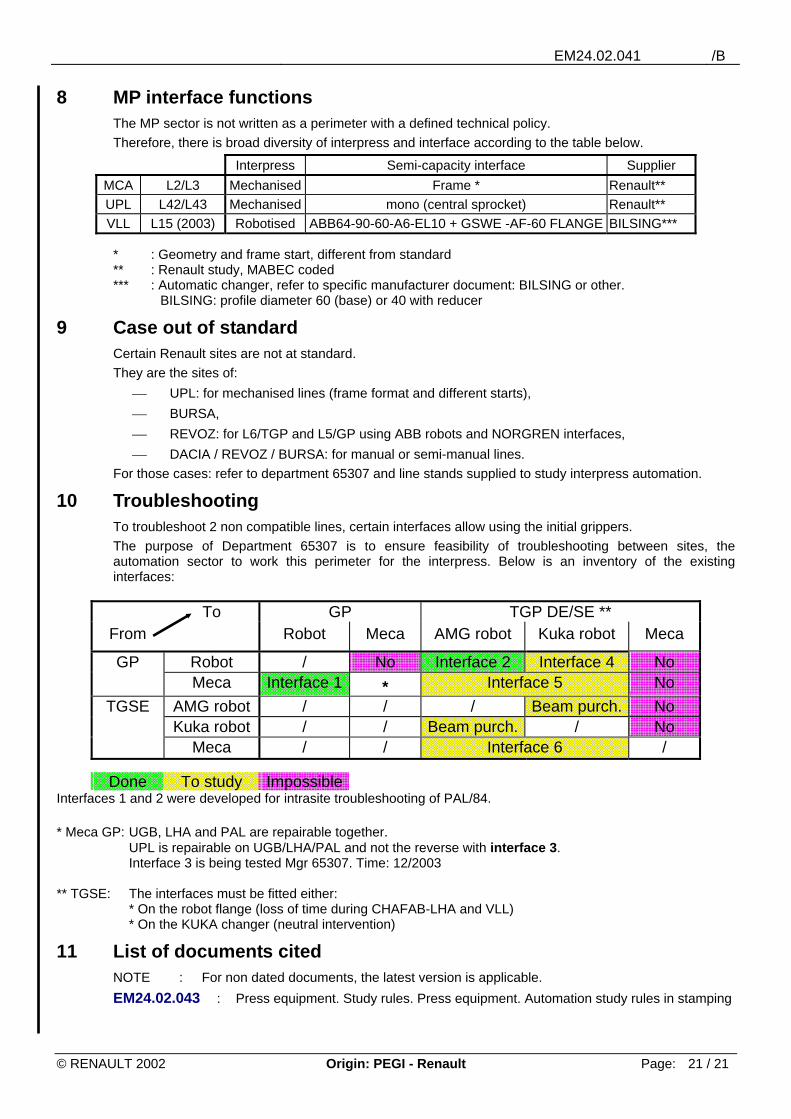
10 Troubleshooting To troubleshoot 2 non compatible lines, certain interfaces allow using the initial grippers. The purpose of Department 65307 is to ensure feasibility of troubleshooting between sites, the automation sector to work this perimeter for the interpress. Below is an inventory of the existing interfaces:
To GP TGP DE/SE ** From Robot Meca AMG robot Kuka robot Meca
GP Robot / No Interface 2 Interface 4 No Meca Interface 1 * Interface 5 No
TGSE AMG robot / / / Beam purch. No Kuka robot / / Beam purch. / No
Meca / / Interface 6 /
Done To study Impossible Interfaces 1 and 2 were developed for intrasite troubleshooting of PAL/84. * Meca GP: UGB, LHA and PAL are repairable together. UPL is repairable on UGB/LHA/PAL and not the reverse with interface 3. Interface 3 is being tested Mgr 65307. Time: 12/2003 ** TGSE: The interfaces must be fitted either: * On the robot flange (loss of time during CHAFAB-LHA and VLL) * On the KUKA changer (neutral intervention)
11 List of documents cited NOTE : For non dated documents, the latest version is applicable. EM24.02.043 : Press equipment. Study rules. Press equipment. Automation study rules in stamping