preset counters - hecotron · preset counters are counting devices with control functions. ma ny...
TRANSCRIPT
113
Pres
etCo
unte
rs
Components E N C O D E R S C O U N T E R S C O N T R O L L E R S I N D I C A T O R S R E L A Y S P R I N T E R S C U T T E R S
Preset Counters
Typical applications:
Control of order-related quantities
Simple length cutting controlwith e.g. cable, fibre, threador wire
Length cutting with fast andslow travel
Dosage and filling Coarse/fine dosage rates Lift or curtain control Coil winding control
Production process controlwith batch counter
PTB approved length control Job data collection over
interfaces Decentralised counting for
PLC and PC applications, withintegrated display
Maintenance interval control
Preset counters are counting devices with control functions. Many dif-ferent applications can be handled using the various versions whichare available. Depending on your requirements, you can choose fromelectronic, electro-mechanical, pneumatic or mechanical models.
Most of the electronic preset counters have two presets and, using aninitial switching point, they can control fast/slow positioning orcoarse/fine dosage rates, for instance
114 Components E N C O D E R S C O U N T E R S C O N T R O L L E R S I N D I C A T O R S R E L A Y S P R I N T E R S C U T T E R S
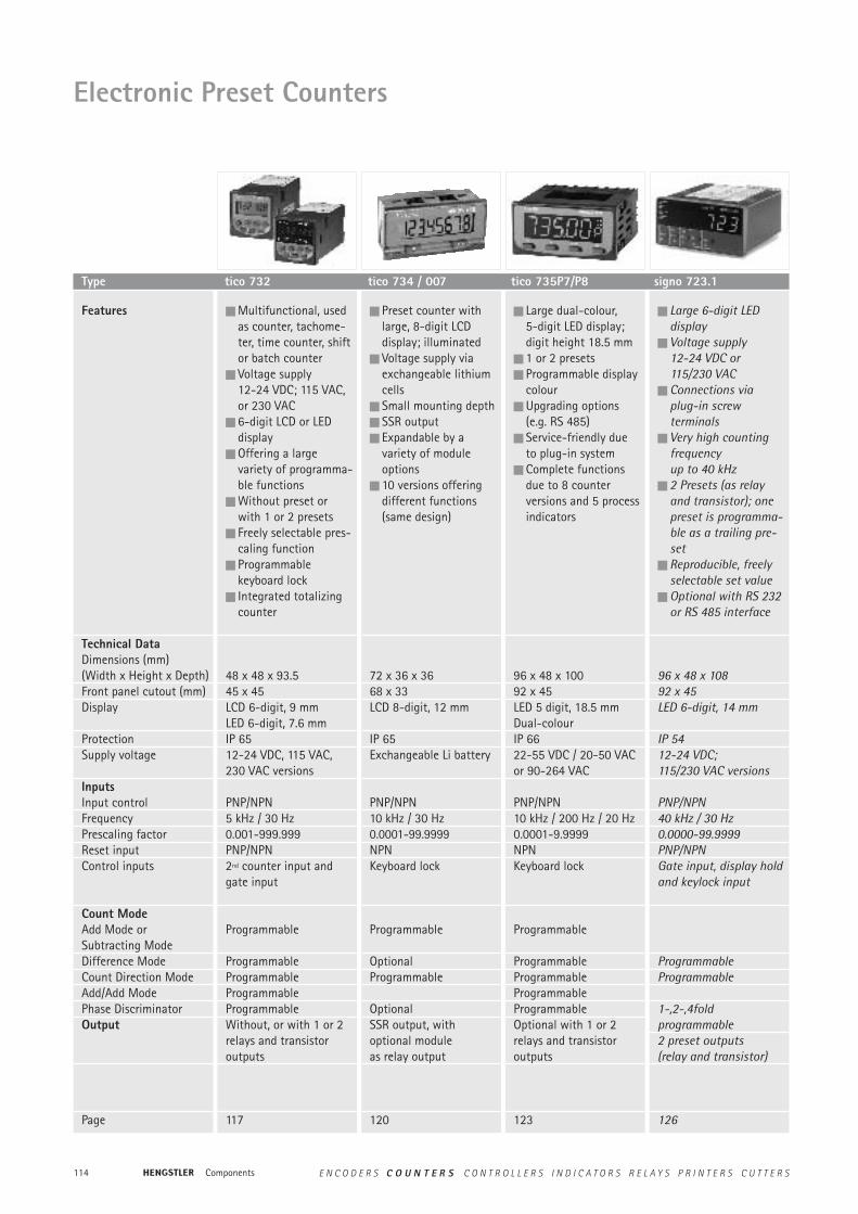
Electronic Preset Counters
Features
Technical DataDimensions (mm)(Width x Height x Depth)Front panel cutout (mm)Display
ProtectionSupply voltage
InputsInput controlFrequencyPrescaling factorReset inputControl inputs
Count ModeAdd Mode orSubtracting ModeDifference ModeCount Direction ModeAdd/Add ModePhase DiscriminatorOutput
Page
Multifunctional, usedas counter, tachome-ter, time counter, shiftor batch counter
Voltage supply 12-24 VDC; 115 VAC,or 230 VAC
6-digit LCD or LEDdisplay
Offering a largevariety of programma-ble functions
Without preset orwith 1 or 2 presets
Freely selectable pres-caling function
Programmable keyboard lock
Integrated totalizingcounter
48 x 48 x 93.545 x 45LCD 6-digit, 9 mmLED 6-digit, 7.6 mmIP 6512-24 VDC, 115 VAC, 230 VAC versions
PNP/NPN5 kHz / 30 Hz0.001-999.999PNP/NPN2nd counter input andgate input
Programmable
ProgrammableProgrammableProgrammableProgrammableWithout, or with 1 or 2 relays and transistor outputs
117
Preset counter withlarge, 8-digit LCD display; illuminated
Voltage supply viaexchangeable lithiumcells
Small mounting depth SSR output Expandable by a
variety of moduleoptions
10 versions offeringdifferent functions(same design)
72 x 36 x 3668 x 33LCD 8-digit, 12 mm
IP 65Exchangeable Li battery
PNP/NPN10 kHz / 30 Hz0.0001-99.9999NPNKeyboard lock
Programmable
OptionalProgrammable
OptionalSSR output, with optional moduleas relay output
120
Large dual-colour, 5-digit LED display;digit height 18.5 mm
1 or 2 presets Programmable display
colour Upgrading options
(e.g. RS 485) Service-friendly due
to plug-in system Complete functions
due to 8 counter versions and 5 processindicators
96 x 48 x 10092 x 45LED 5 digit, 18.5 mmDual-colourIP 6622-55 VDC / 20-50 VACor 90-264 VAC
PNP/NPN10 kHz / 200 Hz / 20 Hz0.0001-9.9999NPNKeyboard lock
Programmable
ProgrammableProgrammableProgrammableProgrammableOptional with 1 or 2 relays and transistor outputs
123
Large 6-digit LED display
Voltage supply 12-24 VDC or 115/230 VAC
Connections via plug-in screw terminals
Very high countingfrequency up to 40 kHz
2 Presets (as relayand transistor); onepreset is programma-ble as a trailing pre-set
Reproducible, freelyselectable set value
Optional with RS 232or RS 485 interface
96 x 48 x 10892 x 45LED 6-digit, 14 mm
IP 5412-24 VDC; 115/230 VAC versions
PNP/NPN40 kHz / 30 Hz0.0000-99.9999PNP/NPNGate input, display holdand keylock input
ProgrammableProgrammable
1-,2-,4fold programmable2 preset outputs (relay and transistor)
126
Type tico 732 tico 734 / 007 tico 735P7/P8 signo 723.1

115
Pres
etCo
unte
rs
Components E N C O D E R S C O U N T E R S C O N T R O L L E R S I N D I C A T O R S R E L A Y S P R I N T E R S C U T T E R S
Features
Technical DataDimensions (mm)(Width x Height x Depth)Front panel cutout (mm)Display
Digit heightProtectionPulse voltage
Power consumptionReset
Operating temperatureDuty cycleAccessories
Dimensions (mm) (with panel frame)Panel frame cutout (mm)
Page
Adding preset counter Display 3-digit or
5-digit with perma-nently visible presets
Manual, electrical, orautomatic reset
Plugs into modularsystem 400
Easy to service
50 x 50 x 92.5
50 x 503; 5, depending on version 4 mmIP 3024 VDC, 24 VAC,115 VAC, 230 VACDC 2.5 W; AC 2.75 VAManual, electrical -depending on version;optional: automatic reset- 10…50 °C100 % at 25 °CPanel frame, connectionbox, reset automaticmodule100 % duty cycle module60 x 75 x 88
55 x 55
134
Adding preset counter Display 3-digit or
5-digit with perma-nently visible presets
Manual, electrical, orautomatic reset
Available with diffe-rent front panel sizes
Compact design
60 x 75 x 72.555 x 53.2 x 72.552 x 523; 5, depending on version 4 mmIP 3024 VDC, 24 VAC,115 VAC, 230 VACDC 2.5 W; AC 2.75 VAManual, electrical -depending on version
- 10…50 °C100 % at 25 °C
136
Subtracting presetcounter
Display 3-digit or 5-digit with perma-nently visible presets
Manual, electrical, orautomatic reset
Plugs into modularsystem 400
Easy to service
50 x 50 x 92.5
50 x 503; 5, depending on version 4 mmIP 3024 VDC, 24 VAC, 115 VAC, 230 VACDC 2.5 W; AC 2.75 VAManual, electrical -depending on versionoptional: automatic reset- 10…50 °C100 % at 25 °CPanel frame, connectionbox, reset automaticmodule100 % duty cycle module60 x 75 x 88
55 x 55
138
Electromechanical Preset Counters
Type Type 486–487 Type 886–887 Type 446 / 447
116 Components E N C O D E R S C O U N T E R S C O N T R O L L E R S I N D I C A T O R S R E L A Y S P R I N T E R S C U T T E R S
Features
Technical DataDimensions (mm)(Width x Height x Depth)DigitsDigit heightProtectionReset
Drive
Torque/Actuating distanceMax. speedMax. no. of strokesTransmission ratioMountingAccessories
Page
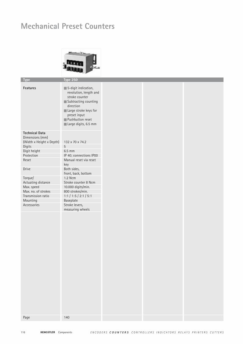
5-digit indication, revolution, length andstroke counter
Subtracting countingdirection
Large stroke keys forpreset input
Pushbutton reset Large digits, 6.5 mm
132 x 70 x 74.256.5 mmIP 40; connections IP00Manual reset via reset keyBoth sides, front, back, bottom1.2 NcmStroke counter 8 Ncm10.000 digits/min.800 strokes/min.1:1 / 1:5 / 2:1 / 5:1BaseplateStroke levers, measuring wheels
140
Mechanical Preset Counters
Type Type 250
117
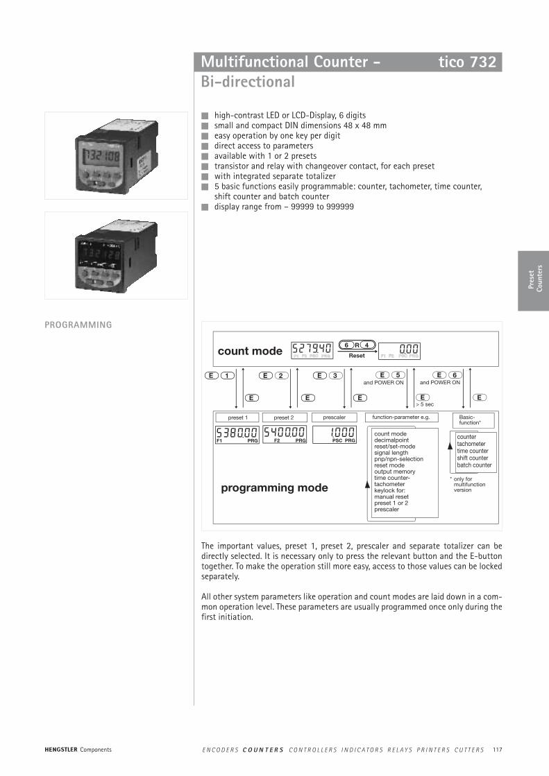
tico 007Multifunctional Counter -Bi-directional
high-contrast LED or LCD-Display, 6 digits small and compact DIN dimensions 48 x 48 mm easy operation by one key per digit direct access to parameters available with 1 or 2 presets transistor and relay with changeover contact, for each preset with integrated separate totalizer 5 basic functions easily programmable: counter, tachometer, time counter,
shift counter and batch counter display range from – 99999 to 999999
PROGRAMMING
The important values, preset 1, preset 2, prescaler and separate totalizer can bedirectly selected. It is necessary only to press the relevant button and the E-buttontogether. To make the operation still more easy, access to those values can be lockedseparately.
All other system parameters like operation and count modes are laid down in a com-mon operation level. These parameters are usually programmed once only during thefirst initiation.
tico 732
Pres
etCo
unte
rs
Components E N C O D E R S C O U N T E R S C O N T R O L L E R S I N D I C A T O R S R E L A Y S P R I N T E R S C U T T E R S
F1 F2 PSC PRG F1 F2 PSC PRG
F1 PRG PRGF2 PRGPSC
Reset
R 46
E
E
E
5 E 6
E
E
E
32E
E
1E
count mode
programming mode
and POWER ON and POWER ON
> 5 sec
preset 1 preset 2 prescaler function-parameter e.g. Basic-function*
count modedecimalpointreset/set-modesignal lengthpnp/npn-selectionreset modeoutput memorytime counter-tachometerkeylock for:manual resetpreset 1 or 2prescaler
* only formultifunction version
countertachometertime countershift counterbatch counter
118
Technical data
TECHNICAL DATA
General
Counter
Tacho
Time-counter
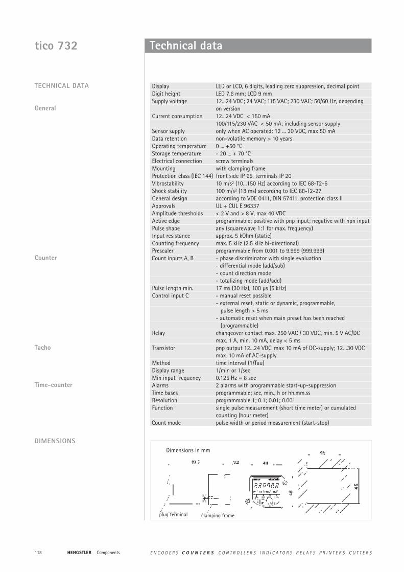
Display LED or LCD, 6 digits, leading zero suppression, decimal pointDigit height LED 7.6 mm; LCD 9 mmSupply voltage 12...24 VDC; 24 VAC; 115 VAC; 230 VAC; 50/60 Hz, depending
on versionCurrent consumption 12...24 VDC < 150 mA
100/115/230 VAC < 50 mA; including sensor supplySensor supply only when AC operated: 12 ... 30 VDC, max 50 mAData retention non-volatile memory > 10 yearsOperating temperature 0 ... +50 °CStorage temperature - 20 ... + 70 °CElectrical connection screw terminalsMounting with clamping frameProtection class (IEC 144) front side IP 65, terminals IP 20Vibrostability 10 m/s2 (10...150 Hz) according to IEC 68-T2-6Shock stability 100 m/s2 (18 ms) according to IEC 68-T2-27General design according to VDE 0411, DIN 57411, protection class IIApprovals UL + CUL E 96337Amplitude thresholds < 2 V and > 8 V, max 40 VDCActive edge programmable; positive with pnp input; negative with npn inputPulse shape any (squarewave 1:1 for max. frequency)Input resistance approx. 5 kOhm (static)Counting frequency max. 5 kHz (2.5 kHz bi-directional)Prescaler programmable from 0.001 to 9.999 (999.999)Count inputs A, B - phase discriminator with single evaluation
- differential mode (add/sub)- count direction mode- totalizing mode (add/add)
Pulse length min. 17 ms (30 Hz), 100 µs (5 kHz)Control input C - manual reset possible
- external reset, static or dynamic, programmable,pulse length > 5 ms
- automatic reset when main preset has been reached (programmable)
Relay changeover contact max. 250 VAC / 30 VDC, min. 5 V AC/DCmax. 1 A, min. 10 mA, delay < 5 ms
Transistor pnp output 12...24 VDC max 10 mA of DC-supply; 12…30 VDCmax. 10 mA of AC-supply
Method time interval (1/Tau)Display range 1/min or 1/secMin input frequency 0.125 Hz = 8 secAlarms 2 alarms with programmable start-up-suppressionTime bases programmable; sec, min., h or hh.mm.ssResolution programmable 1; 0.1; 0.01; 0.001Function single pulse measurement (short time meter) or cumulated
counting (hour meter)Count mode pulse width or period measurement (start-stop)
DIMENSIONS
tico 732
Dimensions in mm
clamping frameplug terminal
Components E N C O D E R S C O U N T E R S C O N T R O L L E R S I N D I C A T O R S R E L A Y S P R I N T E R S C U T T E R S

119
Technical data
Display Preset 12–24 VDC 24 VAC 115 VAC 230 VAC
LCD – 0 732 000 0 732 071 0 732 037 0 732 001LCD 1 0 732 002 0 732 073 0 732 031 0 732 003LCD 2 0 732 012 0 732 078 0 732 049 0 732 013LED – 0 732 018 0 732 080 0 732 055 0 732 019LED 1 0 732 020 0 732 0821 0 732 057 0 732 021LED 2 0 732 030 0 732 087 0 732 067 0 732 031
Important: Only versions with 2 presets or without preset can be used as tachometers.
ORDER INFORMATION
Display
LCD
LED
Funktion
Tachometer
Zeitzähler +Summenzähler
Schichtzähler*
Partiezähler*
ohne Ausgang
1 Ausgang(1 Relais,1 Transistor)
2 Ausgänge(2 Relais,2 Transistors)
12 - 24 VDC
230 VAC
Ausgänge Spannungs-versorgung
Zähler +Summenzähler
100 VAC
115 VAC
DIMENSIONS
POSSIBLE VARIANTS
tico 732
For versions with no output, pins 7–9 and 15-17 are not connected.
VDC 1 Rel/1 Trans
VDC 2 Rel/2 Trans
VAC 1 Rel/1 Trans
VAC 2 Rel/2 Trans
Pres
etCo
unte
rs
Components E N C O D E R S C O U N T E R S C O N T R O L L E R S I N D I C A T O R S R E L A Y S P R I N T E R S C U T T E R S
120
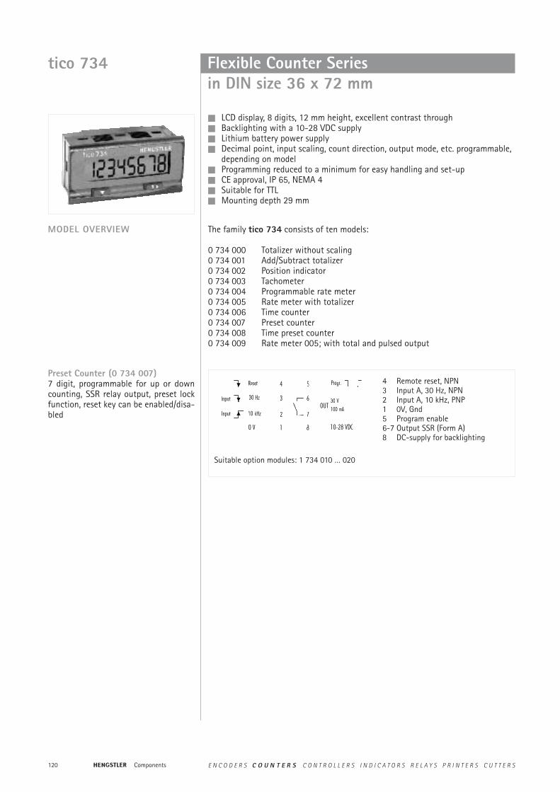
LCD display, 8 digits, 12 mm height, excellent contrast through Backlighting with a 10-28 VDC supply Lithium battery power supply Decimal point, input scaling, count direction, output mode, etc. programmable,
depending on model Programming reduced to a minimum for easy handling and set-up CE approval, IP 65, NEMA 4 Suitable for TTL Mounting depth 29 mm
MODEL OVERVIEW
Flexible Counter Seriesin DIN size 36 x 72 mm
The family tico 734 consists of ten models:
0 734 000 Totalizer without scaling0 734 001 Add/Subtract totalizer0 734 002 Position indicator0 734 003 Tachometer0 734 004 Programmable rate meter0 734 005 Rate meter with totalizer0 734 006 Time counter0 734 007 Preset counter0 734 008 Time preset counter0 734 009 Rate meter 005; with total and pulsed output
tico 734
4 Remote reset, NPN3 Input A, 30 Hz, NPN2 Input A, 10 kHz, PNP1 0V, Gnd5 Program enable6-7 Output SSR (Form A)8 DC-supply for backlighting
Suitable option modules: 1 734 010 … 020
Preset Counter (0 734 007)7 digit, programmable for up or downcounting, SSR relay output, preset lockfunction, reset key can be enabled/disa-bled
Components E N C O D E R S C O U N T E R S C O N T R O L L E R S I N D I C A T O R S R E L A Y S P R I N T E R S C U T T E R S
121
tico 007
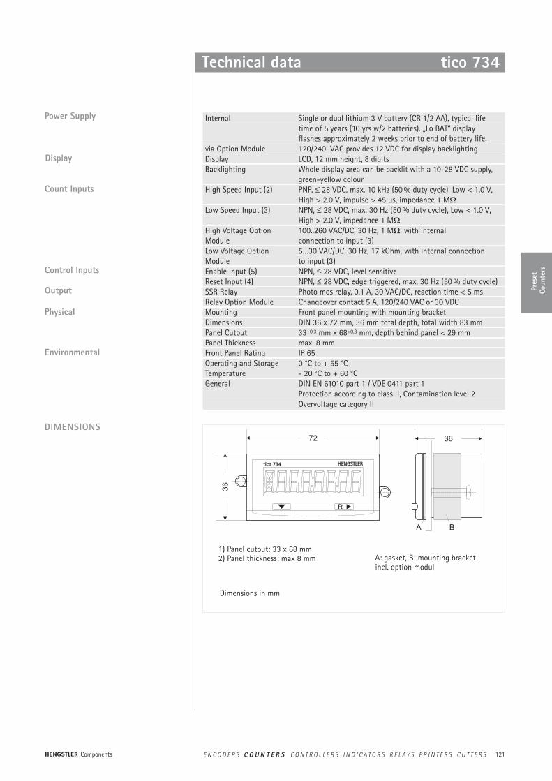
Internal Single or dual lithium 3 V battery (CR 1/2 AA), typical lifetime of 5 years (10 yrs w/2 batteries). „Lo BAT“ display flashes approximately 2 weeks prior to end of battery life.
via Option Module 120/240 VAC provides 12 VDC for display backlighting Display LCD, 12 mm height, 8 digits Backlighting Whole display area can be backlit with a 10-28 VDC supply,
green-yellow colourHigh Speed Input (2) PNP, ≤ 28 VDC, max. 10 kHz (50 % duty cycle), Low < 1.0 V,
High > 2.0 V, impulse > 45 µs, impedance 1 MΩLow Speed Input (3) NPN, ≤ 28 VDC, max. 30 Hz (50 % duty cycle), Low < 1.0 V,
High > 2.0 V, impedance 1 MΩHigh Voltage Option 100..260 VAC/DC, 30 Hz, 1 MΩ, with internal Module connection to input (3)Low Voltage Option 5…30 VAC/DC, 30 Hz, 17 kOhm, with internal connection Module to input (3)Enable Input (5) NPN, ≤ 28 VDC, level sensitiveReset Input (4) NPN, ≤ 28 VDC, edge triggered, max. 30 Hz (50 % duty cycle)SSR Relay Photo mos relay, 0.1 A, 30 VAC/DC, reaction time < 5 msRelay Option Module Changeover contact 5 A, 120/240 VAC or 30 VDCMounting Front panel mounting with mounting bracketDimensions DIN 36 x 72 mm, 36 mm total depth, total width 83 mmPanel Cutout 33+0,3 mm x 68+0,3 mm, depth behind panel < 29 mmPanel Thickness max. 8 mmFront Panel Rating IP 65Operating and Storage 0 °C to + 55 °CTemperature - 20 °C to + 60 °CGeneral DIN EN 61010 part 1 / VDE 0411 part 1
Protection according to class II, Contamination level 2 Overvoltage category II
Technical data tico 734
Control Inputs
Output
Physical
Environmental
Count Inputs
Display
Power Supply
DIMENSIONS
A: gasket, B: mounting bracketincl. option modul
Dimensions in mm
1) Panel cutout: 33 x 68 mm2) Panel thickness: max 8 mm
Pres
etCo
unte
rs
Components E N C O D E R S C O U N T E R S C O N T R O L L E R S I N D I C A T O R S R E L A Y S P R I N T E R S C U T T E R S
122
FUNCTIONS OVERVIEW
tico 734 Technical data
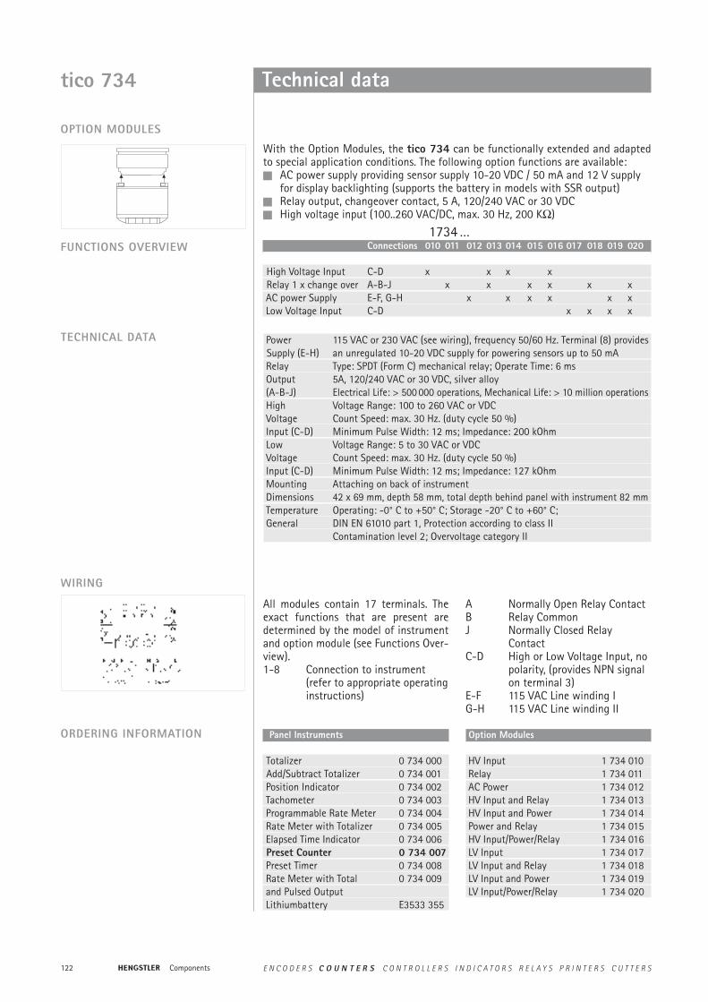
Power 115 VAC or 230 VAC (see wiring), frequency 50/60 Hz. Terminal (8) provides Supply (E-H) an unregulated 10-20 VDC supply for powering sensors up to 50 mARelay Type: SPDT (Form C) mechanical relay; Operate Time: 6 msOutput 5A, 120/240 VAC or 30 VDC, silver alloy(A-B-J) Electrical Life: > 500 000 operations, Mechanical Life: > 10 million operationsHigh Voltage Range: 100 to 260 VAC or VDCVoltage Count Speed: max. 30 Hz. (duty cycle 50 %)Input (C-D) Minimum Pulse Width: 12 ms; Impedance: 200 kOhmLow Voltage Range: 5 to 30 VAC or VDCVoltage Count Speed: max. 30 Hz. (duty cycle 50 %)Input (C-D) Minimum Pulse Width: 12 ms; Impedance: 127 kOhmMounting Attaching on back of instrumentDimensions 42 x 69 mm, depth 58 mm, total depth behind panel with instrument 82 mmTemperature Operating: -0° C to +50° C; Storage -20° C to +60° C;General DIN EN 61010 part 1, Protection according to class II
Contamination level 2; Overvoltage category II
OPTION MODULES
With the Option Modules, the tico 734 can be functionally extended and adaptedto special application conditions. The following option functions are available: AC power supply providing sensor supply 10-20 VDC / 50 mA and 12 V supply
for display backlighting (supports the battery in models with SSR output) Relay output, changeover contact, 5 A, 120/240 VAC or 30 VDC High voltage input (100..260 VAC/DC, max. 30 Hz, 200 KΩ)
Connections 010 011 012 013 014 015 016 017 018 019 020
High Voltage Input C-D x x x xRelay 1 x change over A-B-J x x x x x x AC power Supply E-F, G-H x x x x x xLow Voltage Input C-D x x x x
1734 …
TECHNICAL DATA
WIRING
ORDERING INFORMATION Panel Instruments
Totalizer 0 734 000Add/Subtract Totalizer 0 734 001Position Indicator 0 734 002Tachometer 0 734 003Programmable Rate Meter 0 734 004Rate Meter with Totalizer 0 734 005Elapsed Time Indicator 0 734 006Preset Counter 0 734 007Preset Timer 0 734 008Rate Meter with Total 0 734 009and Pulsed OutputLithiumbattery E3533 355
Option Modules
HV Input 1 734 010Relay 1 734 011AC Power 1 734 012HV Input and Relay 1 734 013HV Input and Power 1 734 014Power and Relay 1 734 015HV Input/Power/Relay 1 734 016LV Input 1 734 017LV Input and Relay 1 734 018LV Input and Power 1 734 019LV Input/Power/Relay 1 734 020
All modules contain 17 terminals. Theexact functions that are present aredetermined by the model of instrumentand option module (see Functions Over-view).1-8 Connection to instrument
(refer to appropriate operatinginstructions)
A Normally Open Relay ContactB Relay CommonJ Normally Closed Relay
ContactC-D High or Low Voltage Input, no
polarity, (provides NPN signal on terminal 3)
E-F 115 VAC Line winding IG-H 115 VAC Line winding II
Components E N C O D E R S C O U N T E R S C O N T R O L L E R S I N D I C A T O R S R E L A Y S P R I N T E R S C U T T E R S
123
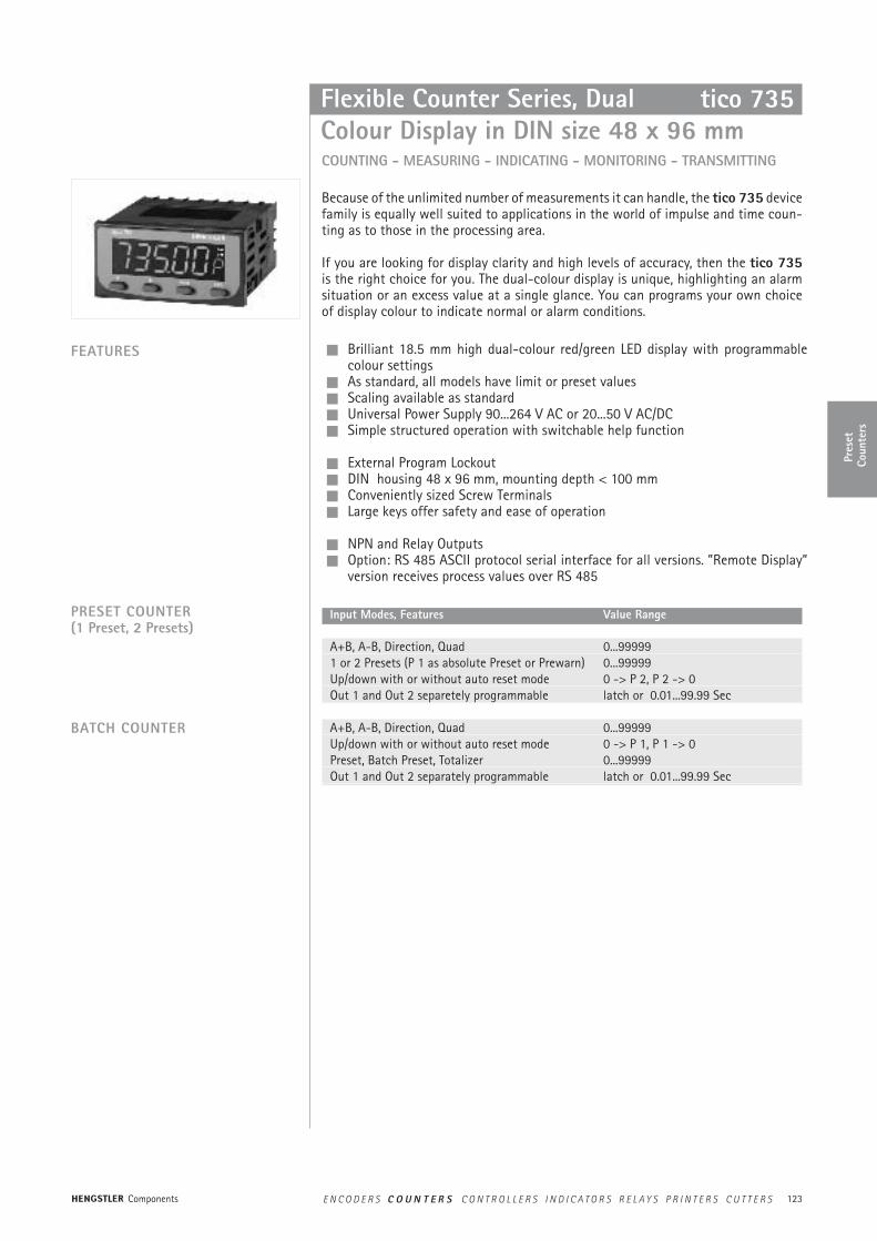
Flexible Counter Series, DualColour Display in DIN size 48 x 96 mm
Input Modes, Features Value Range
A+B, A-B, Direction, Quad 0...999991 or 2 Presets (P 1 as absolute Preset or Prewarn) 0...99999Up/down with or without auto reset mode 0 -> P 2, P 2 -> 0Out 1 and Out 2 separetely programmable latch or 0.01...99.99 Sec
A+B, A-B, Direction, Quad 0...99999Up/down with or without auto reset mode 0 -> P 1, P 1 -> 0Preset, Batch Preset, Totalizer 0...99999Out 1 and Out 2 separately programmable latch or 0.01...99.99 Sec
tico 735
COUNTING - MEASURING - INDICATING - MONITORING - TRANSMITTING
Because of the unlimited number of measurements it can handle, the tico 735 devicefamily is equally well suited to applications in the world of impulse and time coun-ting as to those in the processing area.
If you are looking for display clarity and high levels of accuracy, then the tico 735is the right choice for you. The dual-colour display is unique, highlighting an alarmsituation or an excess value at a single glance. You can programs your own choiceof display colour to indicate normal or alarm conditions.
FEATURES Brilliant 18.5 mm high dual-colour red/green LED display with programmablecolour settings
As standard, all models have limit or preset values Scaling available as standard Universal Power Supply 90...264 V AC or 20...50 V AC/DC Simple structured operation with switchable help function
External Program Lockout DIN housing 48 x 96 mm, mounting depth < 100 mm Conveniently sized Screw Terminals Large keys offer safety and ease of operation
NPN and Relay Outputs Option: RS 485 ASCII protocol serial interface for all versions. ”Remote Display”
version receives process values over RS 485
PRESET COUNTER (1 Preset, 2 Presets)
BATCH COUNTER
Pres
etCo
unte
rs
Components E N C O D E R S C O U N T E R S C O N T R O L L E R S I N D I C A T O R S R E L A Y S P R I N T E R S C U T T E R S

124
10096
48
tico 735
PGM RST
DIMENSIONS
Technical data
DISPLAY AND KEYBOARD
PHYSICAL
OPERATING CONDITIONS
APPROVALS
OPTION: RS 485
Primary Display Red/Green, 7 segment LED, 5 digits, height 18.5 mmSecondary Display single digit 7 segment LED, height 7 mm, red/greenOutput Indicators 2 red LEDs for OUT 1 and OUT 2 statusKeyboard 4 rubber keys for programming and manual reset
Front Dimensions DIN 48 mm x 96 mm, 110 mm total depthMounting Front panel mounting (mounting bracket supplied)Panel Cutout 45 mm x 92 mm, panel thickness max 12 mmConstruction Front carrier with PCBs can be pulled outTerminals Screw Type (combination head)
Power Supply 90 - 264 V AC 50/60 Hz (electrically separated from all inputs and outputs) or 20...50 V AC / 22...55 V DC
Temperature Operation: 0 °C to +55 °C (32 °F to 131 °F)Storage: -20 °C to +60 °C (-4 °F to 176 °F)
Relative Humidity 0 to 90 %, non-condensing
Protection Frontpanel IP 66CE EN 50082-1/92-95; EN 50081-1/92, -2/94Safety DIN EN 61010 part 1; protection according to class IIGeneral UL, CUL, Overvoltage cat. II, Contamination level 2
Type RS 485, serial asynchronous, Open ASCII, Master-Slave, up to 99 zones
Parameters 9600...1200 Bd, 1 start, 7 data, 1 stop, even parity
tico 735
Dimensions in mm
Components E N C O D E R S C O U N T E R S C O N T R O L L E R S I N D I C A T O R S R E L A Y S P R I N T E R S C U T T E R S
125
129 8 7 6 5 4 3
10
11
12
13 14 15 16 17 18 19 20 21
22
23
24
RS 485B A + 0V Relais OUT1
LinearOutput
+
-
0V
OU
T1N
PN
CTRL
1
CTRL
2
Geb
er-
vers
org.
0V
Inpu
t A
Inpu
t B
OU
T2N
PN
NC
RelaisOUT2
NC
~ ~90-264 VAC
22-50VDC/ACoder
Technical data tico 735
ORDERING DATA
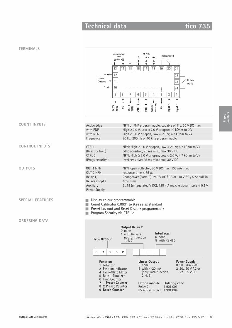
TERMINALS
SPECIAL FEATURES
CONTROL INPUTS
OUTPUTS
COUNT INPUTS Active Edge NPN or PNP programmable; capable of TTL; 30 V DC maxwith PNP High ≥ 3.0 V, Low < 2.0 V or open; 10 kOhm to 0 Vwith NPN High ≥ 3.0 V or open, Low < 2.0 V; 4.7 kOhm to V+Frequency 20 Hz, 200 Hz or 10 kHz programmable
CTRL1 NPN; High ≥ 3.0 V or open, Low < 2.0 V; 4,7 kOhm to V+ (Reset or hold) edge sensitive; 25 ms min., max 30 V DCCTRL 2 NPN; High ≥ 3.0 V or open, Low < 2.0 V; 4,7 kOhm to V+(Progr. security)) level sensitive; 25 ms min.; max 30 V DC
OUT 1 NPN NPN, open collector; 30 V DC max; 100 mA maxOUT 2 NPN response time < 75 µsRelay 1, Changeover (Form C); 240 V AC / 3A or 110 V AC / 5 A; pull-in Relays 2 (opt.) time 8 msAuxiliary 9...15 (unregulated V DC), 125 mA max; residual ripple < 0.5 VPower Supply
Display colour programmable Count Calibrator 0.0001 to 9.9999 as standard Preset Lockout and Reset Disable programmable Program Security via CTRL 2
0 7 3 5 P
Type 0735 P
Function1 Totalizer2 Position Indicator4 Tacho/Rate Meter5 Rate + Totalizer6 Time Counter7 1 Preset Counter8 2 Preset Counter9 Batch Counter
Power Supply0 90…264 V AC2 20…50 V AC or
22…55 V DC
Output Relay 20 none1 with Relay 2
not for function1, 6, 7
Interfaces0 none5 with RS 485
Linear Output0 none3 with 4-20 mA
(only with function 2, 4, 5)
Option module Ordering codeRelay 2 1 901 001RS 485 interface 1 901 004
Pres
etCo
unte
rs
Components E N C O D E R S C O U N T E R S C O N T R O L L E R S I N D I C A T O R S R E L A Y S P R I N T E R S C U T T E R S

126
AABB
signo 723PP11PP22SSeettPPSSCC
Large, 6-digit, 14 mm high LED display Up/down counter with prescaler 2 presets, one programmable as trailing preset Easy direct selection by 2 function keys 2 relay outputs with change-over contacts Keypad can be secured against unauthorized access npn/pnp-programming of inputs RS 232 / RS 485 interface optional
DISPLAY
Variable Preset Counter signo 723.1
6-digit LED display with 14 mm high figures, easy to read, decimal point can be programmed.
PROGRAMMING
Direct access with function-keys F1 and F2
Operation level 2 Operation level 3
P 1:Preselection 1
P 2:Preselection 2
SET: setvalue PSC: Prescaler
-,-,-,- Decimalpoint
systemparameters
Operation level 1
SET: set value
Section A Shows the actual counting position when in counting mode, andthe changeable parameters when in programming mode.
Section B: LED indicators showing the active output signal, and in program-ming mode indicating the changeable parameter.
Programming of signo 723.1 is divided into 3 operation levels and direct access.Direct access: Preselection 1 and 2 can be directly selected by the function
keys F1 and F2Operation level 1: Includes the set valueOperation level 2: Includes machine parameters and application specific
parameters.Operation level 3: Includes system parameters like operation modes and count
modes, which mormally are programmed during start-up pro-cedure.
Unauthorized programming of the signo 723.1 is prevented by a control input, whichcan lock the operation levels as well as the operation keys.
Components E N C O D E R S C O U N T E R S C O N T R O L L E R S I N D I C A T O R S R E L A Y S P R I N T E R S C U T T E R S
127
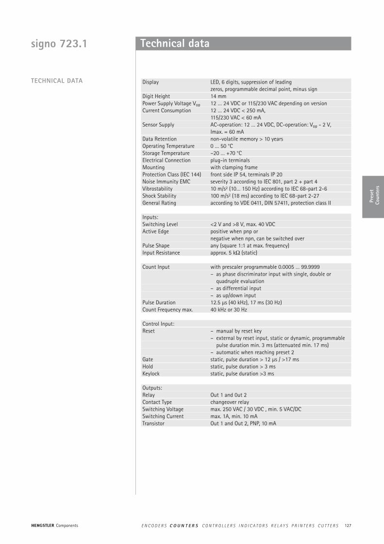
signo 723.1 Technical data
Display LED, 6 digits, suppression of leadingzeros, programmable decimal point, minus sign
Digit Height 14 mm Power Supply Voltage Vop 12 … 24 VDC or 115/230 VAC depending on version Current Consumption 12 … 24 VDC < 250 mA,
115/230 VAC < 60 mASensor Supply AC-operation: 12 … 24 VDC, DC-operation: Vop - 2 V,
Imax. = 60 mA Data Retention non-volatile memory > 10 yearsOperating Temperature 0 … 50 °C Storage Temperature –20 … +70 °C Electrical Connection plug-in terminals Mounting with clamping frame Protection Class (IEC 144) front side IP 54, terminals IP 20Noise Immunity EMC severity 3 according to IEC 801, part 2 + part 4Vibrostability 10 m/s2 (10… 150 Hz) according to IEC 68-part 2-6Shock Stability 100 m/s2 (18 ms) according to IEC 68-part 2-27General Rating according to VDE 0411, DIN 57411, protection class II
Inputs:Switching Level <2 V and >8 V, max. 40 VDC Active Edge positive when pnp or
negative when npn, can be switched overPulse Shape any (square 1:1 at max. frequency)Input Resistance approx. 5 kΩ (static)
Count Input with prescaler programmable 0.0005 … 99.9999 – as phase discriminator input with single, double or
quadruple evaluation– as differential input – as up/down input
Pulse Duration 12.5 µs (40 kHz), 17 ms (30 Hz) Count Frequency max. 40 kHz or 30 Hz
Control Input: Reset – manual by reset key
– external by reset input, static or dynamic, programmablepulse duration min. 3 ms (attenuated min. 17 ms)
– automatic when reaching preset 2 Gate static, pulse duration > 12 µs / >17 ms Hold static, pulse duration > 3 msKeylock static, pulse duration >3 ms
Outputs:Relay Out 1 and 0ut 2 Contact Type changeover relaySwitching Voltage max. 250 VAC / 30 VDC , min. 5 VAC/DCSwitching Current max. 1A, min. 10 mATransistor Out 1 and Out 2, PNP, 10 mA
TECHNICAL DATA
Pres
etCo
unte
rs
Components E N C O D E R S C O U N T E R S C O N T R O L L E R S I N D I C A T O R S R E L A Y S P R I N T E R S C U T T E R S
128
plug-interminals clamping frame
dimensionsin mm
723
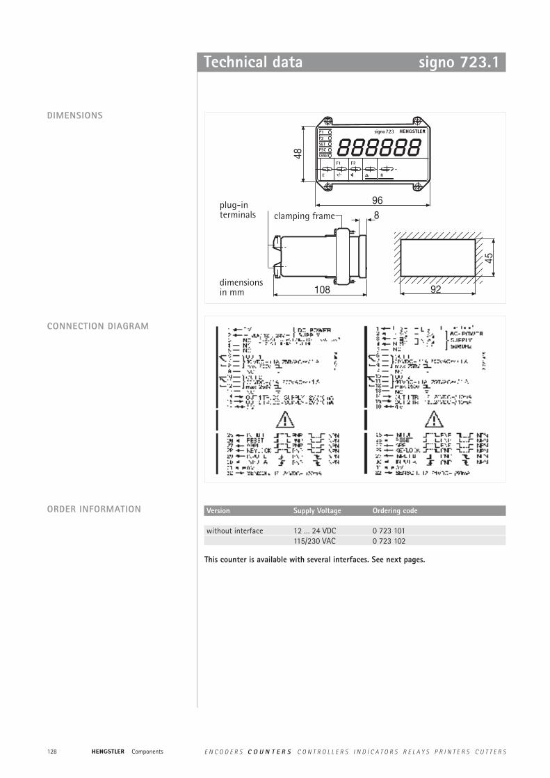
DIMENSIONS
Technical data signo 723.1
CONNECTION DIAGRAM
ORDER INFORMATION Version Supply Voltage Ordering code
without interface 12 … 24 VDC 0 723 101115/230 VAC 0 723 102
This counter is available with several interfaces. See next pages.
Components E N C O D E R S C O U N T E R S C O N T R O L L E R S I N D I C A T O R S R E L A Y S P R I N T E R S C U T T E R S
129
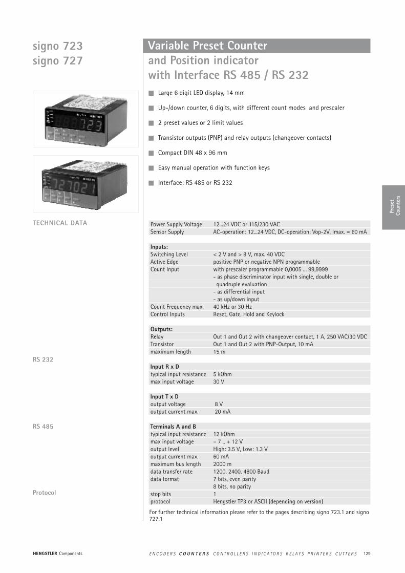
Variable Preset Counter and Position indicator with Interface RS 485 / RS 232
TECHNICAL DATA
Large 6 digit LED display, 14 mm
Up-/down counter, 6 digits, with different count modes and prescaler
2 preset values or 2 limit values
Transistor outputs (PNP) and relay outputs (changeover contacts)
Compact DIN 48 x 96 mm
Easy manual operation with function keys
Interface: RS 485 or RS 232
Protocol
RS 485
Power Supply Voltage 12...24 VDC or 115/230 VACSensor Supply AC-operation: 12...24 VDC, DC-operation: Vop-2V, Imax. = 60 mA
Inputs:Switching Level < 2 V and > 8 V, max. 40 VDCActive Edge positive PNP or negative NPN programmableCount Input with prescaler programmable 0,0005 ... 99,9999
- as phase discriminator input with single, double or quadruple evaluation
- as differential input- as up/down input
Count Frequency max. 40 kHz or 30 HzControl Inputs Reset, Gate, Hold and Keylock
Outputs:Relay Out 1 and Out 2 with changeover contact, 1 A, 250 VAC/30 VDCTransistor Out 1 and Out 2 with PNP-Output, 10 mAmaximum length 15 m
Input R x Dtypical input resistance 5 kOhmmax input voltage 30 V
Input T x Doutput voltage 8 Voutput current max. 20 mA
Terminals A and Btypical input resistance 12 kOhmmax input voltage – 7 .. + 12 Voutput level High: 3.5 V, Low: 1.3 Voutput current max. 60 mAmaximum bus length 2000 mdata transfer rate 1200, 2400, 4800 Bauddata format 7 bits, even parity
8 bits, no paritystop bits 1 protocol Hengstler TP3 or ASCII (depending on version)
RS 232
For further technical information please refer to the pages describing signo 723.1 and signo727.1
signo 723signo 727
Pres
etCo
unte
rs
Components E N C O D E R S C O U N T E R S C O N T R O L L E R S I N D I C A T O R S R E L A Y S P R I N T E R S C U T T E R S

130
Technical data
DIMENSIONS
9648
socket connectorsClamping frame
dimensions in mm
108
panel cutout: 45 x 92
CONNECTION DIAGRAM
PRINTER PROTOCOL FOR 723.1
PRINT MASKS
Protocol Standard ASCII Baudrate 1200, 2400, 4800 BaudData format 7 Bits, even Parity, 1 Stop bit
8 Bits, no Parity, 1 Stop bitLine and Form Feeds programmable before and after printoutCutter Control programmable
The counter allows for the programming of 5 different print masksMask 0 only Count ValueMask 1 Counters: <value> Mask 2 Counter: <value>Mask 3 Counter: <value>
Preset1: <value>Preset2: <value>Set: <value>Prescaler: <value>
Mask 5 Length: <value> m
signo 723signo 727
Components E N C O D E R S C O U N T E R S C O N T R O L L E R S I N D I C A T O R S R E L A Y S P R I N T E R S C U T T E R S
131
Technical data
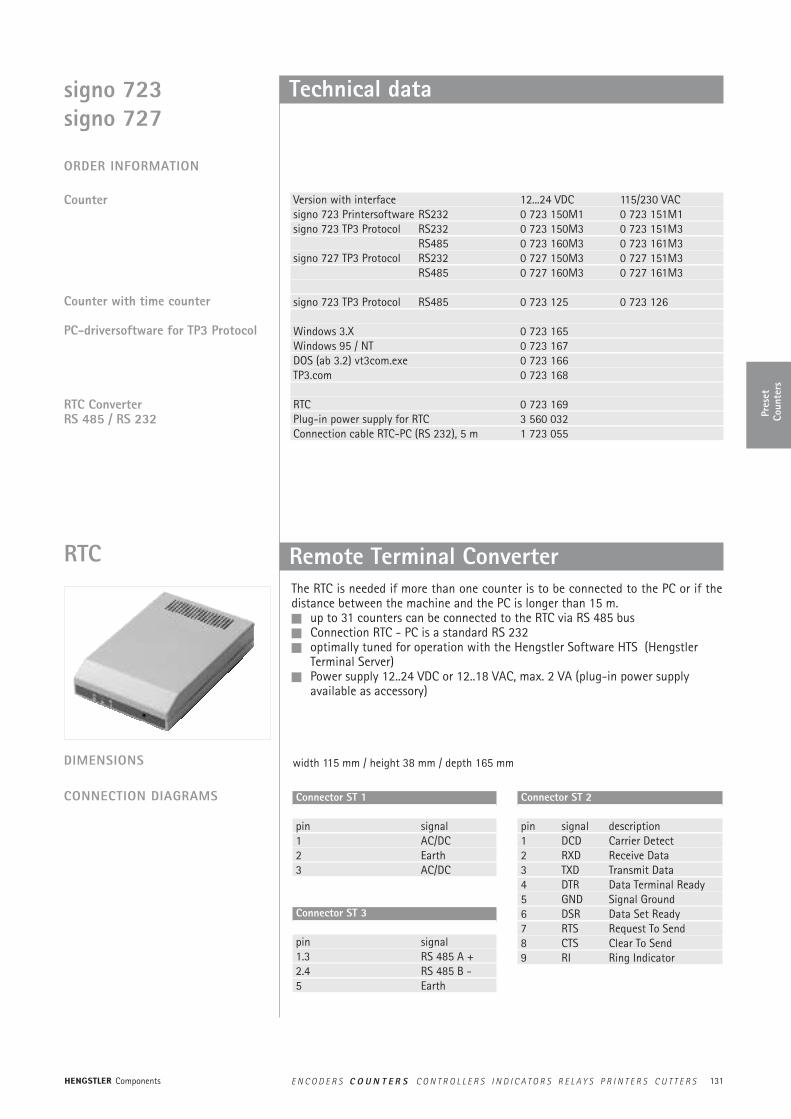
Remote Terminal ConverterRTCThe RTC is needed if more than one counter is to be connected to the PC or if thedistance between the machine and the PC is longer than 15 m. up to 31 counters can be connected to the RTC via RS 485 bus Connection RTC - PC is a standard RS 232 optimally tuned for operation with the Hengstler Software HTS (Hengstler
Terminal Server) Power supply 12..24 VDC or 12..18 VAC, max. 2 VA (plug-in power supply
available as accessory)
DIMENSIONS width 115 mm / height 38 mm / depth 165 mm
CONNECTION DIAGRAMS Connector ST 1
pin signal1 AC/DC2 Earth3 AC/DC
Connector ST 3
pin signal1.3 RS 485 A +2.4 RS 485 B -5 Earth
Connector ST 2
pin signal description1 DCD Carrier Detect2 RXD Receive Data3 TXD Transmit Data4 DTR Data Terminal Ready5 GND Signal Ground6 DSR Data Set Ready7 RTS Request To Send8 CTS Clear To Send9 RI Ring Indicator
ORDER INFORMATION
Counter
Counter with time counter
PC-driversoftware for TP3 Protocol
RTC ConverterRS 485 / RS 232
Version with interface 12...24 VDC 115/230 VACsigno 723 Printersoftware RS232 0 723 150M1 0 723 151M1signo 723 TP3 Protocol RS232 0 723 150M3 0 723 151M3
RS485 0 723 160M3 0 723 161M3signo 727 TP3 Protocol RS232 0 727 150M3 0 727 151M3
RS485 0 727 160M3 0 727 161M3
signo 723 TP3 Protocol RS485 0 723 125 0 723 126
Windows 3.X 0 723 165Windows 95 / NT 0 723 167DOS (ab 3.2) vt3com.exe 0 723 166TP3.com 0 723 168
RTC 0 723 169Plug-in power supply for RTC 3 560 032Connection cable RTC-PC (RS 232), 5 m 1 723 055
signo 723signo 727
Pres
etCo
unte
rs
Components E N C O D E R S C O U N T E R S C O N T R O L L E R S I N D I C A T O R S R E L A Y S P R I N T E R S C U T T E R S

132
Windows Software HTS for Counters
‘ Logical counter adressConst CounterAddress = 25‘ registers of a counterConst CounterValue = 0Const Preset1 = 1Const Preset2 = 2Const Chain = 3
‘ read counter and insert result in table 1Sub Read_Counter()
Set Hts = GetObject(Class:=“Hengstler.TerminalServer.10“)Result = Hts.ReadRegister(CounterAddress; CounterValue)Sheets(„Table1“).Cells(6; 2).Value= Result
Ende Sub
Sub Write_Counter()Data = Sheets(„Table1“).Cells(2; 2).ValueSet Hts = HoleObject(Class:=“Hengstler.TerminalServer.10“)Result = Hts.WriteRegister(CounterAddress; CounterValue; Data)
Ende Sub
EXAMPLE Reading and writing a counter from within MS Excel:
Guided Setup A program group and start icon are created automatically Setup registers the OLE attributes of HTS in the Windows registry DDE- and OLE Server
signo 723signo 727
Components E N C O D E R S C O U N T E R S C O N T R O L L E R S I N D I C A T O R S R E L A Y S P R I N T E R S C U T T E R S
133
867863
267103
467803186786
3267103
1
1
723.181
723.180
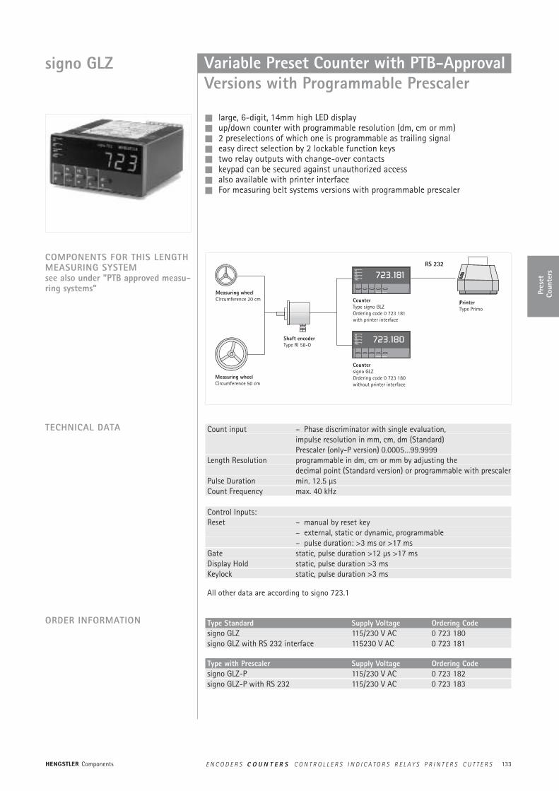
signo GLZ Variable Preset Counter with PTB-ApprovalVersions with Programmable Prescaler
large, 6-digit, 14mm high LED display up/down counter with programmable resolution (dm, cm or mm) 2 preselections of which one is programmable as trailing signal easy direct selection by 2 lockable function keys two relay outputs with change-over contacts keypad can be secured against unauthorized access also available with printer interface For measuring belt systems versions with programmable prescaler
COMPONENTS FOR THIS LENGTHMEASURING SYSTEMsee also under ”PTB approved measu-ring systems”
TECHNICAL DATA Count input – Phase discriminator with single evaluation, impulse resolution in mm, cm, dm (Standard)Prescaler (only-P version) 0.0005…99.9999
Length Resolution programmable in dm, cm or mm by adjusting the decimal point (Standard version) or programmable with prescaler
Pulse Duration min. 12.5 µs Count Frequency max. 40 kHz
Control Inputs: Reset – manual by reset key
– external, static or dynamic, programmable– pulse duration: >3 ms or >17 ms
Gate static, pulse duration >12 µs >17 ms Display Hold static, pulse duration >3 ms Keylock static, pulse duration >3 ms
All other data are according to signo 723.1
Type Standard Supply Voltage Ordering Codesigno GLZ 115/230 V AC 0 723 180signo GLZ with RS 232 interface 115230 V AC 0 723 181
Type with Prescaler Supply Voltage Ordering Codesigno GLZ-P 115/230 V AC 0 723 182signo GLZ-P with RS 232 115/230 V AC 0 723 183
ORDER INFORMATION
Measuring wheelCircumference 20 cm
Measuring wheelCircumference 50 cm
Shaft encoderType RI 58-O
CounterType signo GLZOrdering code 0 723 181with printer interface
Countersigno GLZOrdering code 0 723 180without printer interface
PrinterType Primo
Pres
etCo
unte
rs
Components E N C O D E R S C O U N T E R S C O N T R O L L E R S I N D I C A T O R S R E L A Y S P R I N T E R S C U T T E R S
134
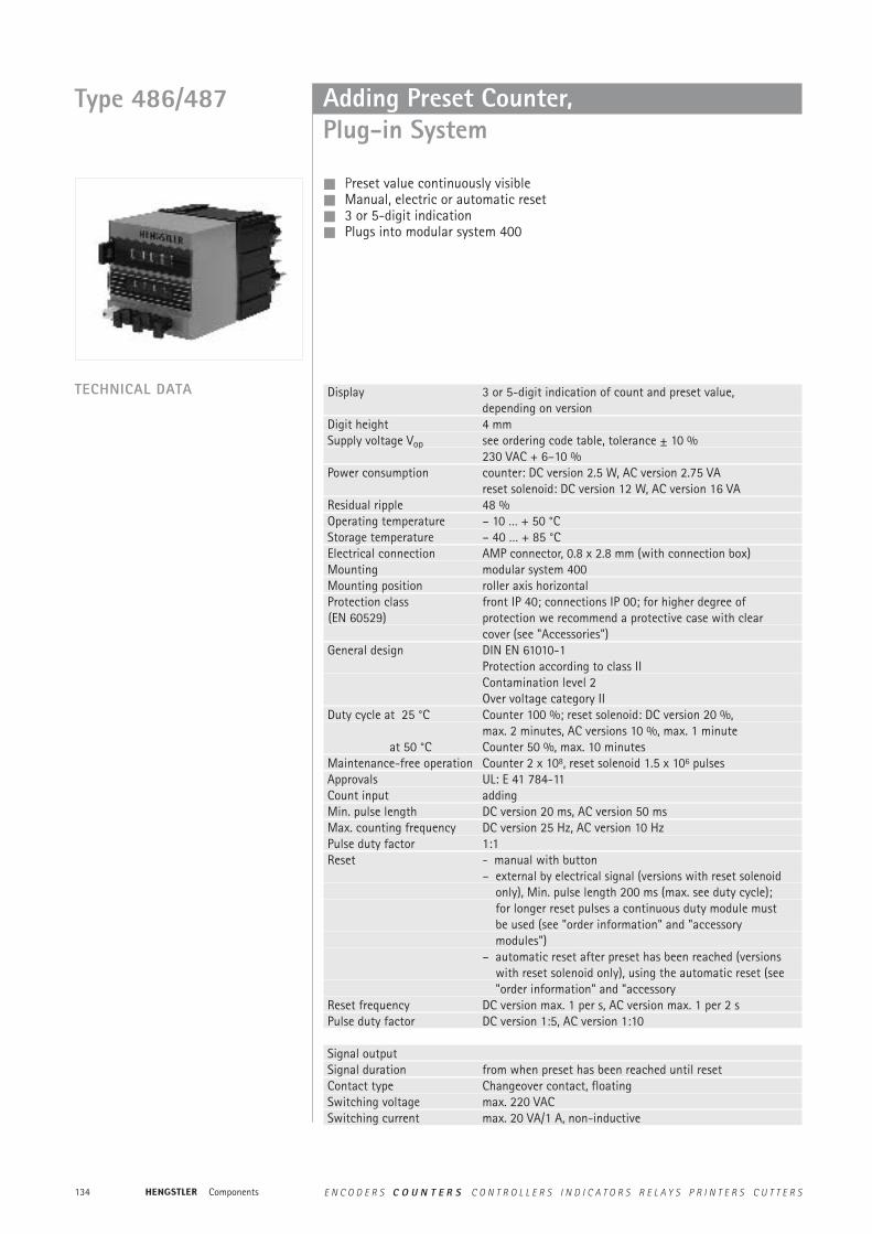
Adding Preset Counter, Plug-in System
Preset value continuously visible Manual, electric or automatic reset 3 or 5-digit indication Plugs into modular system 400
Type 486/487
Display 3 or 5-digit indication of count and preset value, depending on version
Digit height 4 mmSupply voltage Vop see ordering code table, tolerance ± 10 %
230 VAC + 6–10 %Power consumption counter: DC version 2.5 W, AC version 2.75 VA
reset solenoid: DC version 12 W, AC version 16 VAResidual ripple 48 %Operating temperature – 10 … + 50 °C Storage temperature – 40 … + 85 °C Electrical connection AMP connector, 0.8 x 2.8 mm (with connection box)Mounting modular system 400Mounting position roller axis horizontalProtection class front IP 40; connections IP 00; for higher degree of (EN 60529) protection we recommend a protective case with clear
cover (see "Accessories")General design DIN EN 61010-1
Protection according to class IIContamination level 2Over voltage category II
Duty cycle at 25 °C Counter 100 %; reset solenoid: DC version 20 %,max. 2 minutes, AC versions 10 %, max. 1 minute
at 50 °C Counter 50 %, max. 10 minutesMaintenance-free operation Counter 2 x 10⁸, reset solenoid 1.5 x 10⁶ pulses Approvals UL: E 41 784-11Count input addingMin. pulse length DC version 20 ms, AC version 50 msMax. counting frequency DC version 25 Hz, AC version 10 HzPulse duty factor 1:1Reset - manual with button
– external by electrical signal (versions with reset solenoidonly), Min. pulse length 200 ms (max. see duty cycle);for longer reset pulses a continuous duty module must be used (see "order information" and "accessory modules")
– automatic reset after preset has been reached (versions with reset solenoid only), using the automatic reset (see "order information" and "accessory
Reset frequency DC version max. 1 per s, AC version max. 1 per 2 sPulse duty factor DC version 1:5, AC version 1:10
Signal outputSignal duration from when preset has been reached until resetContact type Changeover contact, floatingSwitching voltage max. 220 VACSwitching current max. 20 VA/1 A, non-inductive
TECHNICAL DATA
Components E N C O D E R S C O U N T E R S C O N T R O L L E R S I N D I C A T O R S R E L A Y S P R I N T E R S C U T T E R S

135
Pres
etCo
unte
rs
Technical data
Voltage 3 digits 5 digits cont. duty automaticbutton reset el. reset button reset el. reset module reset
24 V DC 0 487 164 0 487 764 0 486 164 0 486 764 1 486 420 1 486 402 24 V AC 0 487 186* 0 487 786* 0 486 186 0 486 786 1 486 423 1 486 409
115 V AC 0 487 189 0 487 789 0 486 189 0 486 789 1 486 421 1 486 412 230 V AC 0 487 190 0 487 790 0 486 190 0 486 790 1 486 422 1 486 413
Inquire for other voltages
Connection box Ordering Code 1 405 537Key-reset system Ordering Code + SR e.g. 0 487 164 SRPanel frame, black Ordering Code 1 405 492
For further accessories see "Accessories"
** on request** For technical data and dimensioned drawings see accessory modules on page 209
Use only counters with electrical reset.The connection box is integrated in the module.
CONNECTION DIAGRAM
DIMENSIONSWith connection box
All dimensions in mm
With connection box and panelframe
ORDER INFORMATION
Counter
Standard accessories
** **
Type 486/487
Components E N C O D E R S C O U N T E R S C O N T R O L L E R S I N D I C A T O R S R E L A Y S P R I N T E R S C U T T E R S
136
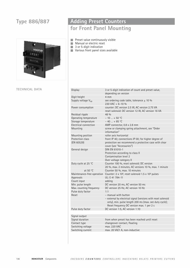
Adding Preset Countersfor Front Panel Mounting
Preset value continuously visible Manual or electric reset 3 or 5-digit indication Various front panel sizes available
TECHNICAL DATA Display 3 or 5-digit indication of count and preset value, depending on version
Digit height 4 mmSupply voltage Vop see ordering code table, tolerance ± 10 %
230 VAC + 6–10 %Power consumption counter: DC version 2.5 W, AC version 2.75 VA
reset solenoid: DC version 12 W, AC version 16 VAResidual ripple 48 %Operating temperature – 10 … + 50 °C Storage temperature – 40 … + 85 °C Electrical connection AMP connector, 0.8 x 2.8 mmMounting screw or clamping spring attachment, see "Order
information"Mounting position roller axis horizontalProtection class front IP 40; connections IP 00; for higher degree of (EN 60529) protection we recommend a protective case with clear
cover (see "Accessories")General design DIN EN 61010-1
Protection according to class IIContamination level 2Over voltage category II
Duty cycle at 25 °C Counter 100 %, reset solenoid: DC version20 %, max. 2 minutes, AC versions 10 %, max. 1 minute
at 50 °C Counter 50 %, max. 10 minutesMaintenance-free operation Counter: 2 x 10⁸, reset solenoid 1.5 x 10⁶ pulses Approvals UL: E 41 784-11Count input addingMin. pulse length DC version 20 ms, AC version 50 msMax. counting frequency DC version 25 Hz, AC version 10 HzPulse duty factor 1:1Reset – manual with button
– external by electrical signal (versions with reset solenoid only), min. pulse length 200 ms (max. see duty cycle); Reset frequency DC version max. 1 per 2 s
Pulse duty factor DC version 1:5, AC version 1:10
Signal outputSignal duration from when preset has been reached until resetContact type changeover contact, floatingSwitching voltage max. 220 VACSwitching current max. 20 VA/1 A, non-inductive
Type 886/887
Components E N C O D E R S C O U N T E R S C O N T R O L L E R S I N D I C A T O R S R E L A Y S P R I N T E R S C U T T E R S
137
Pres
etCo
unte
rs
Technical data
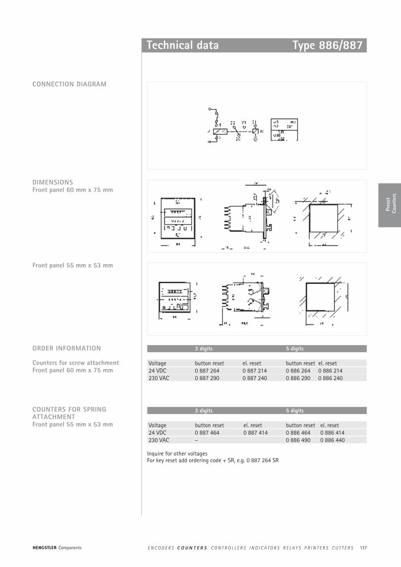
3 digits 5 digits
Voltage button reset el. reset button reset el. reset24 VDC 0 887 264 0 887 214 0 886 264 0 886 214 230 VAC 0 887 290 0 887 240 0 886 290 0 886 240
3 digits 5 digits
Voltage button reset el. reset button reset el. reset24 VDC 0 887 464 0 887 414 0 886 464 0 886 414 230 VAC – 0 886 490 0 886 440
Inquire for other voltages For key reset add ordering code + SR, e.g. 0 887 264 SR
ORDER INFORMATION
Counters for screw attachmentFront panel 60 mm x 75 mm
COUNTERS FOR SPRING ATTACHMENTFront panel 55 mm x 53 mm
CONNECTION DIAGRAM
DIMENSIONSFront panel 60 mm x 75 mm
Front panel 55 mm x 53 mm
Type 886/887
Components E N C O D E R S C O U N T E R S C O N T R O L L E R S I N D I C A T O R S R E L A Y S P R I N T E R S C U T T E R S
138
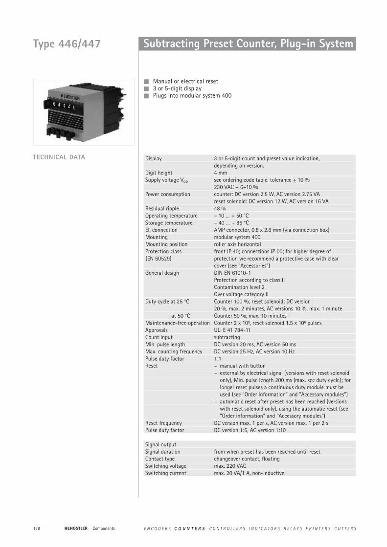
Type 446/447 Subtracting Preset Counter, Plug-in System
Manual or electrical reset 3 or 5-digit display Plugs into modular system 400
TECHNICAL DATA Display 3 or 5-digit count and preset value indication,depending on version.
Digit height 4 mmSupply voltage Vop see ordering code table, tolerance ± 10 %
230 VAC + 6–10 %Power consumption counter: DC version 2.5 W, AC version 2.75 VA
reset solenoid: DC version 12 W, AC version 16 VAResidual ripple 48 %Operating temperature – 10 … + 50 °CStorage temperature – 40 … + 85 °C El. connection AMP connector, 0.8 x 2.8 mm (via connection box)Mounting modular system 400Mounting position roller axis horizontalProtection class front IP 40; connections IP 00; for higher degree of(EN 60529) protection we recommend a protective case with clear
cover (see "Accessories")General design DIN EN 61010-1
Protection according to class IIContamination level 2Over voltage category II
Duty cycle at 25 °C Counter 100 %; reset solenoid: DC version20 %, max. 2 minutes, AC versions 10 %, max. 1 minute
at 50 °C Counter 50 %, max. 10 minutesMaintenance-free operation Counter 2 x 10⁸, reset solenoid 1.5 x 10⁶ pulses Approvals UL: E 41 784-11Count input subtractingMin. pulse length DC version 20 ms, AC version 50 msMax. counting frequency DC version 25 Hz, AC version 10 HzPulse duty factor 1:1Reset – manual with button
– external by electrical signal (versions with reset solenoidonly), Min. pulse length 200 ms (max. see duty cycle); for longer reset pulses a continuous duty module must be used (see "Order information" and "Accessory modules")
– automatic reset after preset has been reached (versions with reset solenoid only), using the automatic reset (see "Order information" and "Accessory modules")
Reset frequency DC version max. 1 per s, AC version max. 1 per 2 sPulse duty factor DC version 1:5, AC version 1:10
Signal outputSignal duration from when preset has been reached until resetContact type changeover contact, floatingSwitching voltage max. 220 VACSwitching current max. 20 VA/1 A, non-inductive
Components E N C O D E R S C O U N T E R S C O N T R O L L E R S I N D I C A T O R S R E L A Y S P R I N T E R S C U T T E R S

139
Pres
etCo
unte
rs
Technical data
CONNECTION DIAGRAM
DIMENSIONS With connection box
All dimensions in mm
With connection box and panel frame
Voltage 3 digits 5 digits cont. duty automaticbutton reset el. reset button reset el. reset module reset
24 V DC 0 447 164 0 447 764 0 446 164 0 446 764 1 486 420 1 486 402 24 V AC 0 447 186 0 447 786 0 446 186 0 446 786 1 486 423 1 486 409
115 V AC 0 447 189 0 447 789 0 446 189 0 446 789 1 486 421 1 486 412 230 V AC 0 447 190 0 447 790 0 446 190 0 446 790 1 486 422 1 486 413
Connection box 1 405 537Panel frame, black 1 405 492Key-reset system Ordering code+ SR e.g. 0 447 164 SR
For further accessories see ”Accessories“.
Inquire for other voltages
** For technical data and dimensioned drawings see “accessory modules”Use only counters with electrical reset.The connection box is integrated in the module.
ORDER INFORMATION
Standard accessories
** **
Type 446/447
Components E N C O D E R S C O U N T E R S C O N T R O L L E R S I N D I C A T O R S R E L A Y S P R I N T E R S C U T T E R S

140
Preset Revolution, Length Measuringor Stroke Counter
5-digit display Large 6.5 mm digits Button reset
Display 5-digit displayDigit height 6.5 mmElectrical connection rear strain relief 4-wire cable, approx. 30 cm longProtection class IP 40, connections IP 00
(EN 60529)General design DIN EN 61010-1
Protection according to class IContamination level 2Over voltage category II
Base plate burnished sheet steelCase die-cast metal, black varnishCap plastic (ABS), greyWeight approx. 800 gCounting mode – + subtracting in specified direction of rotation, adding in
reverse, stroke counter – subtracting in specified directionof rotation
Transmission ratio see "Order information"Speed 10000 increments/min, stroke counter 800 strokes/minActuating angle min. 38°, max. 55° (stroke counter only)Torque 1.2 Ncm, stroke counter 8.0 NcmReset button reset, secured against accidental operation
OutputSignal duration on transition from 00000 to 99999 until resetContact type single-pole changeover contactSwitching voltage max. 125 VDC/250 VACSwitching current max. 20 VA/0.3 A Don’t push the reset pushbutton during the process
TECHNICAL DATA
DIMENSIONS
Dimensions in mm
Type 250
Components E N C O D E R S C O U N T E R S C O N T R O L L E R S I N D I C A T O R S R E L A Y S P R I N T E R S C U T T E R S
141
Pres
etCo
unte
rs
Technical data
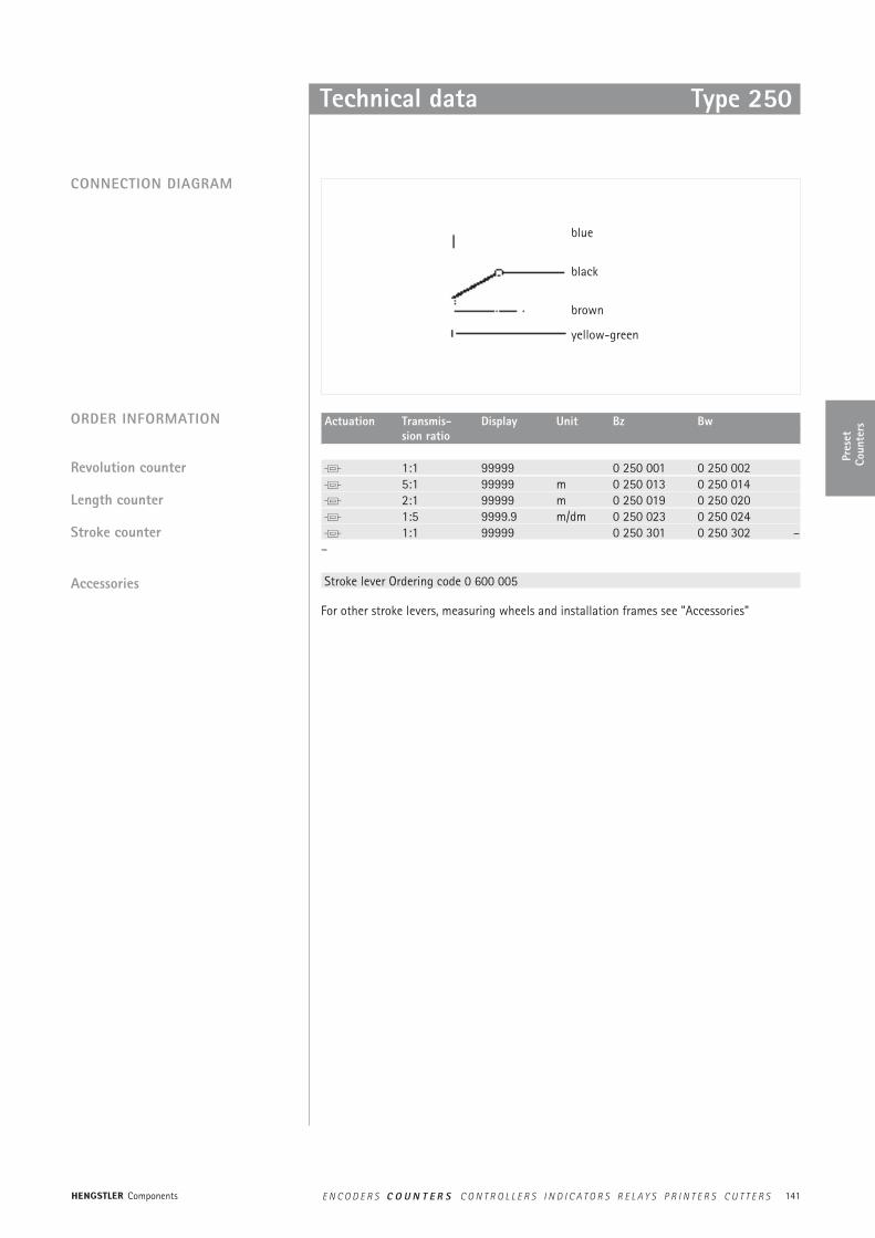
Actuation Transmis- Display Unit Bz Bwsion ratio
1:1 99999 0 250 001 0 250 002 5:1 99999 m 0 250 013 0 250 014 2:1 99999 m 0 250 019 0 250 020 1:5 9999.9 m/dm 0 250 023 0 250 024 1:1 99999 0 250 301 0 250 302 ––
Stroke lever Ordering code 0 600 005
For other stroke levers, measuring wheels and installation frames see "Accessories"
ORDER INFORMATION
Revolution counter
Length counter
Stroke counter
CONNECTION DIAGRAM
Accessories
Type 250
blue
black
brown
yellow-green
Components E N C O D E R S C O U N T E R S C O N T R O L L E R S I N D I C A T O R S R E L A Y S P R I N T E R S C U T T E R S
142
Headline hierNotes
Components E N C O D E R S C O U N T E R S C O N T R O L L E R S I N D I C A T O R S R E L A Y S P R I N T E R S C U T T E R S