presentation, zelio control - measurement and description
TRANSCRIPT

2
PresentationThe RM22 Zelio multifunction control relays monitor the following functions on
3-phase supplies:
Functions RM22TA RM22TU RM22TR RM22TG
Sequence of phases L1, L2 and L3
Phase failure with regeneration
Asymmetry
Undervoltage
Overvoltage and undervoltage
Function performed
Function not performed
Depending on the model these RM22T control relays:
b Accept different nominal 3-phase voltages: up to a 480 V
b Monitor own power supply measured as a true rms value
b Designed for clip-on mounting on DIN rail
b Settings are protected by a sealable cover
b Diagnostic button for load circuit testing
b Relay output status LED
b Fault detection indication LED
b Dial pointer LED indicator for relay power ON status
b Relay output On-delay or Off-delay
Applications
b Control for connection of moving equipments (site equipment, agricultural
equipment, refrigerated trucks)
b Control for protection of persons and equipment against the consequences of
reverse running (lifting, handling, elevators, escalators, etc.)
b Control of sensitive 3-phase supplies
b Protection against the risk of a driving load (phase failure)
b Normal/emergency power supply switching
DescriptionRM22TA RM22TU 1a Voltage range selector switch
1b Voltage range/On-Off delay selector
2 Time delay adjustment potentiometer Tt
3a Asymmetry threshold setting
potentiometer Asym
3b Undervoltage setting potentiometer <U
3c Overvoltage setting potentiometer >U
4 Diagnostic button
RM22TR RM22TG
Un Green LED: indicates that supply to the relay is on
R Yellow LED: indicates relay output state
DEF Yellow LED: indicates fault detection
Presentation, description
Zelio Control - Measurement and control relaysMultifunction 3-phase control relays RM22TA, RM22TU, RM22TR, and RM22TG
L1 L2 L3
12 11 14
22 21 24
2
4
68 14
16
18
20%
R
>U
RM22TR31
DIAGNOSTIC
-2
-4
-6-8 -14
-16
-18
-20%
<U
Def
240
220
208
200
240
220
208
200
Tt
ON
DE
LA
Y
OF
F D
EL
AY
0,1 30s
5
10 20
25
1b
3c
3b4
L1 L2 L3
12 11 14
22 21 24
R
RM22TG20
DIAGNOSTIC
Un
4
L1 L2
12 11 14
22 21 24
R
RM22TA31
DIAGNOSTIC
Def
200208
220
240
8
5
10
12
15%
Asym
L3
Tt
0,1 30s
5
10 20
25
1a
2
3a
4
L1 L2 L3
12 11 14
22 21 24
R
RM22TU23
DIAGNOSTIC
Def
380400
415
440
480
-2
-4
-6-8 -14
-16
-18
-20%
<U
1a
3b
4
RM22T
2
1
3
4
5
6
7
8
9
10
2
1
3
4
5
6
7
8
9
10
28614-EN
version: 1.0
3
Operation
Operating principleMultifunction 3-phase supply control relays monitor:
b Own power supply
b Correct sequencing of phases L1, L2 and L3
b Fault signalling by LED
b Phase failure, including in the case of voltage regeneration
b Undervoltage from - 2…- 20 % of the supply voltage Un
b Overvoltage from 2…20 % of the supply voltage Un
b Asymmetry from 5…15 % of the supply voltage Un
b Voltage selector switch:
v Set the switch to 3-phase supply voltage Un
v Position of this switch is taken into account on energization of the device
v If the switch position is changed while the device is operating, all the LEDs lash but the product continues to operate normally with the voltage selected at the time of
energization preceding the change of position
v If the switch is returned to the original position selected prior to the last
energization, the LED’s return to their normal state
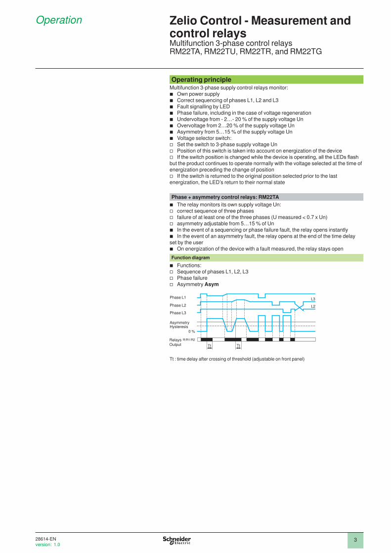
Phase + asymmetry control relays: RM22TA
b The relay monitors its own supply voltage Un:
v correct sequence of three phases
v failure of at least one of the three phases (U measured < 0.7 x Un)
v asymmetry adjustable from 5…15 % of Un
b In the event of a sequencing or phase failure fault, the relay opens instantly
b In the event of an asymmetry fault, the relay opens at the end of the time delay
set by the user
b On energization of the device with a fault measured, the relay stays open
Function diagram
b Functions:
v Sequence of phases L1, L2, L3
v Phase failure
v Asymmetry Asym
Tt : time delay after crossing of threshold (adjustable on front panel)
Zelio Control - Measurement and control relaysMultifunction 3-phase control relaysRM22TA, RM22TU, RM22TR, and RM22TG
L2
L3
0 %
Tt Tt
R/R1/R2
Phase L3
Phase L2
Phase L1
HysteresisAsymmetry
Relays Output
2
1
3
4
5
6
7
8
9
10
2
1
3
4
5
6
7
8
9
10
28614-EN
version: 1.0
4
Operation (continued) Zelio Control - Measurement and control relaysMultifunction 3-phase control relaysRM22TA, RM22TU, RM22TR, and RM22TG
Operating principle (continued)
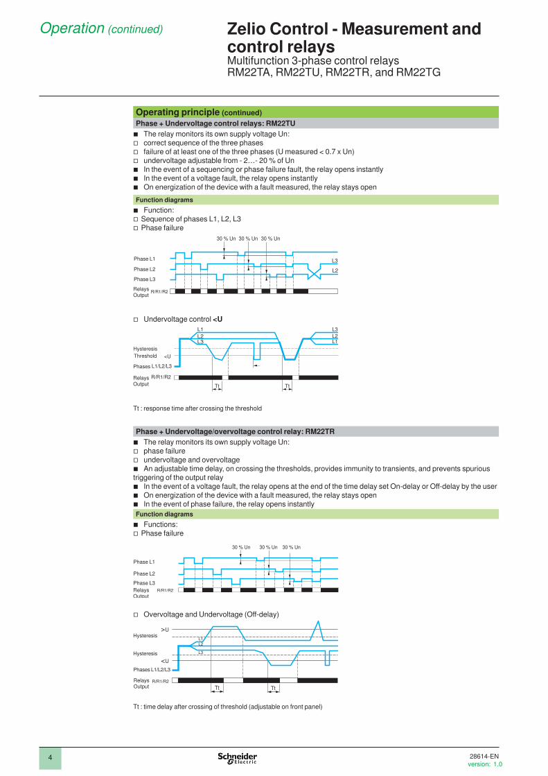
Phase + Undervoltage control relays: RM22TU
b The relay monitors its own supply voltage Un:
v correct sequence of the three phases
v failure of at least one of the three phases (U measured < 0.7 x Un)
v undervoltage adjustable from - 2…- 20 % of Un
b In the event of a sequencing or phase failure fault, the relay opens instantly
b In the event of a voltage fault, the relay opens instantly
b On energization of the device with a fault measured, the relay stays open
Function diagrams
b Function:
v Sequence of phases L1, L2, L3
v Phase failure
30 % Un 30 % Un30 % Un
L3
L2
R/R1/R2
Phase L3
Phase L2
Phase L1
Relays Output
v Undervoltage control <U
R/R1/R2
L1/L2/L3
L1
L2L3
L2
L3
L1
Tt Tt
<UThreshold
Hysteresis
Relays Output
Phases
Tt : response time after crossing the threshold
Phase + Undervoltage/overvoltage control relay: RM22TR
b The relay monitors its own supply voltage Un:
v phase failure
v undervoltage and overvoltage
b An adjustable time delay, on crossing the thresholds, provides immunity to transients, and prevents spurious
triggering of the output relay
b In the event of a voltage fault, the relay opens at the end of the time delay set On-delay or Off-delay by the user
b On energization of the device with a fault measured, the relay stays open
b In the event of phase failure, the relay opens instantly
Function diagrams
b Functions:
v Phase failure
30 % Un 30 % Un30 % Un
R/R1/R2
Phase L3
Phase L2
Phase L1
Relays Output
v Overvoltage and Undervoltage (Off-delay)
<U
>U
L1
L2
L3
Tt Tt
R/R1/R2
Phases L1/L2/L3
RelaysOutput
Hysteresis
Hysteresis
Tt : time delay after crossing of threshold (adjustable on front panel)
2
1
3
4
5
6
7
8
9
10
2
1
3
4
5
6
7
8
9
10
28614-EN
version: 1.0

5
Operation (continued)
references
Operating principle (continued)
Phase control relays: RM22TG
b The RM22TG relay monitors:
v Correct sequencing of the three phases
v Total loss of one or more of the phases
b When phase sequence and voltages are correct (> a 183 V), the output relays are closed
and the yellow LED is on
b When there is a sequencing fault or total loss of one or more phases (detected as soon as
one of the voltages drops below 100 V) the relay opens instantly and the LED goes off
b On energization of the device with a fault measured, the relay stays open
Function diagram
b Function:
v Sequence of phases L1, L2, L3
v Phase failure
100 %
0 %
100 %
0 %
100 %
0 %
Tr Tr Tr Tr
L3
L2
R/R1/R2
Phase L1
Phase L2
Phase L3
RelaysOutput
Tr: response time on appearance of a fault
ReferencesFunction Rated 3-phase
supply voltage Measurement range
Time delay Output Reference Weight
V V kg/lb
b Phase sequence
b Phase failureb Asymmetry
a 200…240 a 200…240 Off delay (0.1...30 s)
2 C/O 8 A RM22TA31 0.090/ 0.198
a 380…480 a 380…480 Off delay (0.1...30 s)
2 C/O 8 A RM22TA33 0.090/ 0.198
b Phase sequence
b Phase failureb Undervoltage
and overvoltage
a 200…240 a 200…240 On/Off delay (0.1...30 s)
2 C/O 8 A RM22TR31 0.090/ 0.198
a 380…480 a 380…480 On/Off delay (0.1...30 s)
2 C/O 8 A RM22TR33 0.090/ 0.198
b Phase sequence
b Phase failureb Undervoltage
a 200…240 a 200…240 No 2 C/O 8 A RM22TU21 0.090/ 0.198
a 380…480 a 380…480 No 2 C/O 8 A RM22TU23 0.090/ 0.198
b Phase sequence
b Phase failure
a 208…480 a 183…528 No 2 C/O 8 A RM22TG20 0.090/ 0.198
Zelio Control - Measurement and control relaysMultifunction 3-phase control relaysRM22TA, RM22TU, RM22TR, and RM22TG
RM22TG20
RM22TA31 RM22TR31
RM22TU21
2
1
3
4
5
6
7
8
9
10
2
1
3
4
5
6
7
8
9
10
28614-EN
version: 1.0

22
PresentationRM22UA and RM22UB are DC voltage or 1-phase control relays which monitor the
following functions:
Functions RM22 UA2MR UA3MR UA33MT UB34
Overvoltage (without memory)
Undervoltage (with/without memory)
Overvoltage (with/without memory)
Overvoltage or undervoltage
(windows mode)
Function performed
Function not performed
The RM22 control relays enable:
b Automatic a.c. or d.c. recognition
b Selection between overvoltage and undervoltage
b Monitor own supply voltage which is measured as true rms value
b Selectable memory function
b Dial pointer LED indicator for relay power ON status
b Relay output status LED
The settings are protected by a sealable cover and the control status is indicated
by a LED. The relays are designed for clip-on mounting on Din rail mounting.
Applications
b Protection of electronic or electromechanical devices against overvoltage and
undervoltage
b Normal/emergency power supply switching
b d.c. motor overspeed control
b Monitoring of a.c. or d.c. supplies
b Battery and Speed monitoring (with tacho-generator)
DescriptionRM22UA2MR RM22UA3MR 1 Coniguration: selection of operating
mode <U (undervoltage), >U
(overvoltage), >U> (overvoltage and
under voltage), MEMORY - NO
MEMORY (with or without memory)
2a Voltage threshold setting potentiometer
U value
2b Undervoltage setting potentiometer <U
2c Overvoltage setting potentiometer >U
3 Time delay adjustment potentiometer Tt
4a Hysteresis adjustment potentiometer
Hys
4b Hysteresis/overvoltage and
undervoltage window mode adjustment
potentiometer Hys/>U>
5 Diagnostic button
6 Coniguration: selection of On-delay or Off-delay
RM22UA33MT RM22UB34
R Yellow LED: indicates relay output state
Presentation, description
Zelio Control - Measurement and control relays1-phase or DC voltage control relays RM22UA and RM22UB
RM22UA31MR
A1 A2 M
12 11 14
22 21 24
R
Hys
RM22UA23MR
DIAGNOSTIC
E1 E2 E3
>U
Value
5
10
15
20 35
40
45
50%
10
20
30
40 70
80
90
100%2c
4a
5
A1 A2 M
12 11 14
E1 E2 E3
22 21 24
U
>
ME
MO
RY
NO
>
ME
MO
RY
R
U
Value
Hys/
>U>
Tt
U >
>
> U
RM22UA31MR
U< U>
< U
DIAGNOSTIC
5
10
15
20 35
40
45
50%
10
20
30
40 70
80
90
100%
0,1 30s
5
10 20
25
1
2a
4b
35
A1+ A2-
12 11 14
22 21 24
O
N
OF
FD
EL
AY
100
120
140
160 220
240
260
300V
R
>U
<U
Tt
RM22UB34
DIAGNOSTIC
80
280
0,1 30s
5
10 20
25
DE
LA
Y
100
120
140
160 220
240
260
300V80
2802b
2c
6
35
A1 A2 M
12 11 14
E1 E2 E3
22 21 24
R
RM22UA33MT
DIAGNOSTIC
U
>
ME
MO
RY
NO
>
ME
MO
RY
10
20
30
40 70
80
90
100%
5
10
15
20 35
40
45
50%
U
Value
Hys/
>U>
Tt
U >
>
> U
U< U>
U<
0,1 30s
5
10 20
25
1
2a
4b
35
RM22UA21MR
2
1
3
4
5
6
7
8
9
10
2
1
3
4
5
6
7
8
9
10
2
1
3
4
5
6
7
8
9
10
2
1
3
4
5
6
7
8
9
10
28615-EN
version: 1.0

33
Operation
Operating principleDC voltage or 1-phase control relays monitor:
b voltages of 1-phase and DC supplies
b its own supply voltage for RM22UB model
An adjustable time delay, on crossing the thresholds, provides immunity to
transients, and prevents spurious triggering of the output relay.
Overvoltage + Undervoltage control relays with/without memory: RM22 UA2MR/ UA3MR/UA33MT
The operating mode is ixed by the user: b Undervoltage with or without memory
b Overvoltage with or without memory
The position of the coniguration switch and the operating mode is read by the product on energization:
b If the coniguration switch is set to an unacceptable position, the product detects a fault, the output relay stays open and the LEDs lash to indicate the position error.
b If the coniguration switch position is changed while the device is operating, all the LEDs lash, but the product continues to operate normally with the function
selected at the time of energization before position change.
b If the coniguration switch is returned to the original position selected prior to the
last energization, the LED’s return to their normal state.
The undervoltage or overvoltage threshold value is set by means of a potentiom-
eter graduated as a percentage of the scale value of U to be monitored.
The hysteresis is adjusted by means of a potentiometer graduated from 5…50 %
of the threshold setting. The hysteresis value must not exceed the limit values of the measuring range.
b Overvoltage without Memory
If the voltage controlled exceeds the threshold setting for a time greater than t hat set on the front panel (0.1…30 s), the output relay opens and LED R goes off.
During the time delay, this LED lashes.As soon as the voltage drops below the value of the threshold setting minus the
hysteresis, the relay instantly closes.
b Undervoltage without Memory
If the voltage controlled falls below the threshold setting for a time greater than
that set on the front panel (0.1…30 s), the output relay opens and LED R goes off.
During the time delay, this LED lashes.As soon as the voltage rises above the value of the threshold setting plus the
hysteresis, the relay instantly closes.
b Overvoltage/Undervoltage with Memory
If “Memory” mode is selected, the relay opens when crossing of the threshold is
detected and then stays in that position. The power must be switched off to reset
the product.
Function diagram
b Function: Overvoltage control > U v without memory
v with memory
Zelio Control - Measurement and control relays1-phase or DC voltage control relays RM22UA and RM22UB
>U
Tt
U
R/R1/R2Relays Output
Hysteresis
Supply Un
Threshold
>U
U
Tt
R/R1/R2RelaysOutput
Hysteresis
Supply Un
Threshold
2
1
3
4
5
6
7
8
9
10
2
1
3
4
5
6
7
8
9
10
2
1
3
4
5
6
7
8
9
10
2
1
3
4
5
6
7
8
9
10
28615-EN
version: 1.0
4
Operation (continued) Zelio Control - Measurement and control relays1-phase or DC voltage control relays RM22UA and RM22UB
Operating principle (continued)
Function diagrams (continued)
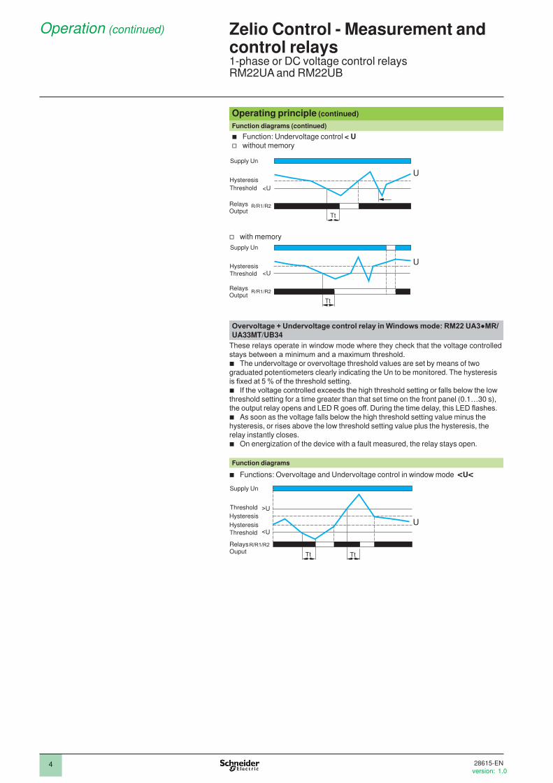
b Function: Undervoltage control < U v without memory
v with memory
Overvoltage + Undervoltage control relay in Windows mode: RM22 UA3MR/UA33MT/UB34
These relays operate in window mode where they check that the voltage controlled
stays between a minimum and a maximum threshold. b The undervoltage or overvoltage threshold values are set by means of two
graduated potentiometers clearly indicating the Un to be monitored. The hysteresis
is ixed at 5 % of the threshold setting. b If the voltage controlled exceeds the high threshold setting or falls below the low
threshold setting for a time greater than that set time on the front panel (0.1…30 s),
the output relay opens and LED R goes off. During the time delay, this LED lashes. b As soon as the voltage falls below the high threshold setting value minus the
hysteresis, or rises above the low threshold setting value plus the hysteresis, the
relay instantly closes.
b On energization of the device with a fault measured, the relay stays open.
Function diagrams
b Functions: Overvoltage and Undervoltage control in window mode <U<
U
<U
Tt
R/R1/R2RelaysOutput
Hysteresis
Supply Un
Threshold
U
Tt
<U
R/R1/R2RelaysOutput
Hysteresis
Supply Un
Threshold
Tt Tt
U
>U
<U
R/R1/R2RelaysOuput
Hysteresis
Supply Un
Threshold
Hysteresis
Threshold
2
1
3
4
5
6
7
8
9
10
2
1
3
4
5
6
7
8
9
10
28615-EN
version: 1.0

5
References
ReferencesFunction Rated supply
voltageMeasurement range
Time delay Output Reference Weight
V V kg/lb
b Overvoltage without memory
z 24…240 z 0.05…5 No 2 C/O 8 A RM22UA21MR 0.110/ 0.242
z 24…240 z 1…100 No 2 C/O 8 A RM22UA22MR 0.110/ 0.242
z 24…240 z 15…500 No 2 C/O 8 A RM22UA23MR 0.110/ 0.242
b Overvoltage and Undervoltage with/without memory
b Overvoltage and Undervoltage with memory window
z 24…240 z 0.05…5 Off delay
(0.1...30 s)
2 C/O 8 A RM22UA31MR 0.110/ 0.242
z 24…240 z 1…100 Off delay
(0.1...30 s)
2 C/O 8 A RM22UA32MR 0.110/ 0.242
z 24…240 z 15…500 Off delay
(0.1...30 s)
2 C/O 8 A RM22UA33MR 0.110/ 0.242
a 380…415 a 15…500 Off delay
(0.1...30 s)
2 C/O 8 A RM22UA33MT 0.110/ 0.242
b Overvoltage and Undervoltage without memory
z 110…240 z 80…300 On/Off
delay
(0.1...30 s)
2 C/O 8 A RM22UB34 0.090/ 0.198
Zelio Control - Measurement and control relays1-phase or DC voltage control relays RM22UA and RM22UB
RM22UA33MT
RM22UA23MR RM22UA33MR
RM22UB34
2
1
3
4
5
6
7
8
9
10
2
1
3
4
5
6
7
8
9
10
28615-EN
version: 1.0

2
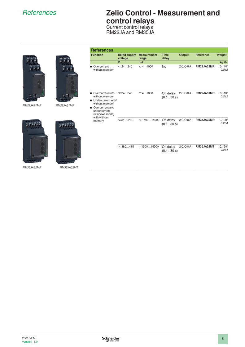
PresentationMultifunction current control relays RM22JA and RM35JA
monitor the following functions.
Functions RM22JA21MR RM22JA31MR RM35JA 32MR/32MT
Overcurrent
(without memory)
Overcurrent
(with/without memory)
Undercurrent
(with/without memory)
Overcurrent and
undercurrent
(with/without memory)
(windows mode)
Function performed
Function not performed
These control relays enable:
b Automatic a.c. or d.c. recognition
b Selection between overcurrent and undercurrent
b Measurement as true rms value
b Selectable memory function
b Dial pointer LED indicator for relay power ON status
b Relay output status LED
The settings are protected by a sealable cover and the control status is indicated
by a LED. The relays are designed for clip-on mounting on Din rail mount.
Applications
b Excitation control of d.c. machines
b Load state control of motors and generators
b Control of current drawn by a 3-phase motor
b Monitoring of heating or lighting circuits
b Control of pump draining (undercurrent)
b Control of overtorque (crushers)
b Monitoring of electromagnetic brakes or clutches.
DescriptionRM22JA21MR RM22JA31MR 1 Coniguration: selection of operating
mode <I (undercurrent), >I (overcurrent), >I> (overcurrent and
undercurrent), MEMORY - NO
MEMORY (with or without memory)
2 Current threshold setting
potentiometer I %
3a Hysteresis adjustment
potentiometer Hys
3b Hysteresis/overcurrent and
undercurrent window mode
adjustment potentiometer Hys/>I>
4 Time delay adjustment
potentiometer Tt
5 Diagnostic button
6 Overcurrent setting potentiometer >IRM35JA32MR RM35JA32MT
R Yellow LED: indicates relay output state.
Presentation, description
Zelio Control - Measurement and control relaysCurrent control relays RM22JA and RM35JA
RM35JA32MT
A1 A2 M
12 11 14
22 21 24
5
10
15
20 35
40
45
50%
R
Hys
RM22JA21MR
DIAGNOSTIC
10
20
30
40 70
80
90
100%
E1 E2 E3
% I I
I>
3a
6
ME
MO
RY
NO
ME
MO
RY
10
20
30
40 70
80
90
100%
5
10
15
20 35
40
45
50%
0,1 30s
5
10 20
25
A1 A2 M
12 11 14
E1 E2 E3
22 21 24
> >
R
Hys/
Tt
>
>
>
RM22JA31MR
<
>
<
DIAGNOSTIC
% I I
I
I I
I> >
I I
I
I I
I
I I
I
I I
I
I I
I
I I
I
3b
2
1
45
<
>
> >
MEMORY
> >
>
<
Hys/
Tt
100%10
20
30
40 70
80
90
50%5
10
15
20 35
40
45
30s0,1
5
10 20
25
A1 A2 E3 E2 E1 M
12 11 14 22 21 24
RM35JA32MT
R
DIAGNOSTIC
% I I
I
I I
I> >
I I
I
I I
I
I I
I
I I
I
I I
I
I I
I
YES NO
3b21
45
A1 A2 E3 E2 E1 M
12 11 14 22 21 24
RM35JA32MR
R
DIAGNOSTIC
<
>
> >
MEMORY
> >
>
<
Hys/
Tt
100%10
20
30
40 70
80
90
50%5
10
15
20 35
40
45
30s0,1
5
10 20
25
% I I
I
I I
I> >
I I
I
I I
I
I I
I
I I
I
I I
I
I I
I
YES NO
3b21
45
RM22JA21MR
2
1
3
4
5
6
7
8
9
10
2
1
3
4
5
6
7
8
9
10
2
1
3
4
5
6
7
8
9
10
2
1
3
4
5
6
7
8
9
10
28616-EN
version: 1.0

3
Operation
Operating principleThe current control relays monitor:
b Current of 1-phase and DC supplies
An adjustable time delay, on crossing the thresholds, provides immunity to
transients, so preventing spurious triggering of the output relay.
Overcurrent + Undercurrent control relays with/without memory: RM22JA1MR/ RM35JA32M
The operating mode is ixed by the user: b Undercurrent with or without memory
b Overcurrent with or without memory
The position of the coniguration switch and the operating mode is read by the product on energization:
b If the coniguration switch is set to an unacceptable position, the product detects a fault, the output relay stays open and the LEDs lash to indicate the position error.
b If the coniguration switch position is changed while the device is operating, all the LEDs lash, but the product continues to operate normally with the function
selected at the time of energization before position change.
b If the coniguration switch is returned to the original position selected prior to the
last energization, the LED’s return to their normal state.
The undercurrent or overcurrent threshold value is set by means of a potentiom-
eter graduated as a percentage of the scale value of I to be monitored.
The hysteresis is adjusted by means of a potentiometer graduated from 5…50 %
of the threshold setting. The hysteresis value must not exceed the limit values of
the measuring range.
b Overcurrent without Memory
If the current controlled exceeds the threshold setting for a time greater than
that set on the front panel (0.1…30 s), the output relay opens and LED R goes off.
During the time delay, this LED lashes.As soon as the current drops below the value of the threshold setting minus the
hysteresis, the relay instantly closes.
b Overcurrent with Memory
If “Memory” mode is selected, the relay opens when crossing of the threshold is
detected and then stays in that position. The power must be switched off to reset
the product.
Function diagram
b Function: Overcurrent detection > I v without memory
v with memory
Note: Ti is not used for this model.
Zelio Control - Measurement and control relaysCurrent control relays RM22JA and RM35JA
R/R1/R2
Tt Tt TiTi
I
>I
Relays
Output
Hysteresis
Supply Un
Threshold
R/R1/R2
Ti Tt Ti
I
>I
Tt
Relays
Output
Hysteresis
Supply Un
Threshold
2
1
3
4
5
6
7
8
9
10
2
1
3
4
5
6
7
8
9
10
2
1
3
4
5
6
7
8
9
10
2
1
3
4
5
6
7
8
9
10
28616-EN
version: 1.0

4
Operation (continued) Zelio Control - Measurement and control relaysCurrent control relays RM22JA and RM35JA
Operating principle (continued)
Overcurrent + Undercurrent control relays with/without memory: RM22JA1MR/ RM35JA32M (continued) b Undercurrent without Memory
If the current controlled falls below the threshold setting for a time greater than that
set on the front panel (0.1…30 s), the output relay opens and LED R goes off. Dur-
ing the time delay, this LED lashes.As soon as the voltage rises above the value of the threshold setting plus the
hysteresis, the relay instantly closes.
b Undercurrent with Memory
If “Memory” mode is selected, the relay opens when crossing of the threshold is
detected and then stays in that position. The power must be switched off to reset
the product.
Function diagrams
b Function: Undercurrent detection <I v without memory
v with memory
Note: Ti is not used for this model.
Overcurrent + Undercurrent control relay in windows mode:
RM22JA1MR/ RM35JA32MThese relays operate in window mode where they check that the current controlled
stays between a minimum and a maximum threshold.
b The undercurrent or overcurrent threshold values are set by means of two
graduated potentiometers clearly indicating the I to be monitored. The hysteresis is
ixed at 5 % of the threshold setting. b If the current controlled exceeds the high threshold setting or falls below the low
threshold setting for a time greater than that set time on the front panel (0.1…30 s),
the output relay opens and LED R goes out. During the time delay, this LED lashes. b As soon as the current falls below the high threshold setting value minus the
hysteresis, or rises above the low threshold setting value plus the hysteresis, the
relay instantly closes.
b On energization of the device with a fault measured, the relay stays open.
Function diagrams
b Functions: Overcurrent and Undercurrent control in window mode <I<
R/R1/R2
TiTt Tt Ti
I
<I
Relays
Output
Hysteresis
Supply Un
Threshold
R/R1/R2
Ti Ti
I<I
Tt Tt
Relays
Output
Hysteresis
Supply Un
Threshold
Without memory
Power Supply
ThresholdHysteresis
HysteresisThreshold
>I
<I
Relays Output Tt
<TtU<Tt
Tt
R/R1/R2
2
1
3
4
5
6
7
8
9
10
2
1
3
4
5
6
7
8
9
10
2
1
3
4
5
6
7
8
9
10
2
1
3
4
5
6
7
8
9
10
28616-EN
version: 1.0
5
References
ReferencesFunction Rated supply
voltageMeasurement range
Time delay
Output Reference Weight
V mA kg/lb
b Overcurrent without memory
z 24…240 z 4…1000 No 2 C/O 8 A RM22JA21MR 0.110/ 0.242
b Overcurrent with/without memory
b Undercurrent with/without memory
b Overcurrent and undercurrent (windows mode) with/without memory
z 24…240 z 4…1000 Off delay
(0.1...30 s)
2 C/O 8 A RM22JA31MR 0.110/ 0.242
z 24…240 z 1500…15000 Off delay
(0.1...30 s)
2 C/O 8 A RM35JA32MR 0.120/ 0.264
a 380…415 a1500…15000 Off delay
(0.1...30 s)
2 C/O 8 A RM35JA32MT 0.120/ 0.264
Zelio Control - Measurement and control relaysCurrent control relays RM22JA and RM35JA
RM35JA32MR
RM22JA21MR RM22JA31MR
RM35JA32MT
2
1
3
4
5
6
7
8
9
10
2
1
3
4
5
6
7
8
9
10
2
1
3
4
5
6
7
8
9
10
2
1
3
4
5
6
7
8
9
10
28616-EN
version: 1.0

2
PresentationLevel control relays RM22LA and RM22LG control one or two levels, with ill or empty function:
Functions RM22LA 32MR/32MT RM22LG 11MR/11MT
Level 1/Level 2
Fill operation
Empty operation
Low sensitivity
Standard sensitivity
High sensitivity
Function performed
Function not performed
The RM22 liquid level control relays enable:
b Dial pointer LED indicator for relay power ON status
b Relay output status LED
The settings are protected by a sealable cover and the control status is indicated
by a LED. The relays are designed for clip-on mounting on Din rail.
Applications
These devices monitor the levels of conductive liquid.
They control the actuation of pumps or valves to regulate levels. They are also
suitable for protecting submersible pumps against dry running, or protecting tanks
from “overlow”. They can also be used to control dosing of liquids in mixingprocesses and to protect heating elements in the event of non immersion.
They have a transparent, hinged cover on their front panel to avoid any accidental
alteration of the settings. This cover can be directly sealed.
b Application examples for compatible liquidsv spring, town, industrial and sea water
v metallic salt, acid or base solutions
v liquid fertilizers
v non concentrated alcohol (< 40 %)
v liquids in the food-processing industry: milk, beer, coffee, etc.
DescriptionRM22LG11MR RM22LG11MT 1 Coniguration: selection of the
operating mode: Fill or Empty, and the
sensitivity range. LS/St/HS
2 Sensitivity control potentiometer (kΩ or %)3 Coniguration: selection of Number of
levels; and On/Off time Delay
4 Time delay control potentiometer Tt
5 Diagnostic button
RM22LA32MR RM22LA32MT
R Yellow LED: indicates relay output state.
Presentation, description
Zelio Control - Measurement and control relaysLiquid level control relays RM22LA and RM22LG
A1 A2 NC
12 11 14
10
20
30 70
80
100
R
Sens
Level
RM22LG11MR
DIAGNOSTIC
5
90
Min Max C
40 60
1 2
KΩ
A1 A2 NC
12 11 14
R
Sens
Level
RM22LG11MT
DIAGNOSTIC
Min Max C
10
20
30 70
80
1005
90
40 60
1 2
KΩ
RM22LA32MT
3 3
2 2
1 1
A1 A2 NC
12 11 14
22 21 24
RM22LA32MT
DIAGNOSTIC
Min Max C
Sens
Level
Tt
St. St.
HS
LS
LS
HS
1
2
1
2
10
20
30 70
80
100%5
90
40 60
ON
D
EL
AY
OF
FD
EL
AY
0,1 30s
5
10 20
25
R
A1 A2 NC
12 11 14
22 21 24
R
Sens
Level
Tt
RM22LA32MR
DIAGNOSTIC
Min Max C
St. St.
HS
LS
LS
HS
1
2
1
2
10
20
30 70
80
100%5
90
40 60
ON
D
EL
AY
OF
FD
EL
AY
0,1 30s
5
10 20
25
3 3
2 2
1 1
4 45 5
5 5
RM22LG11MR
2
1
3
4
5
6
7
8
9
10
2
1
3
4
5
6
7
8
9
10
28617-EN
version: 1.0

3
Operation
Operating principleThe liquid level control relays are designed to control levels of:
b Conductive liquid
Relay controls the levels of conductive liquids and measures the levels by means
of resistive probes.
The operating principle is based on measurement of the apparent resistance of the
liquid between two submerged probes. When this value is less than the threshold
setting on the front panel of the device, the relay changes state. To avoid electro-
lytic phenomena, an a.c. current runs across the probes.
The control of one single level can be achieved by using the 2nd selector switch.
In this case, the Max. level probe stays up in the air and an adjustable time delay avoids any wave effect. These two products activate their output relay when a tank is
either emptying or illing.
Level control relay with adjustable sensitivity range
In these relays, a selector coniguration switch on the front panel allows selection of the required sensitivity range and the empty or ill function. A second switch allows selection of the number of levels (1 or 2) and the type of time delay in the
case of level 1 mode.
The coniguration of these switches is taken into account on energization.b If the coniguration switch is set to an unacceptable position, the product detects a fault, the output relay stays open and the LEDs lash to signal the position error. b If the coniguration switch position is changed while the device is operating, all the LEDs lash, but the product continues to operate normally with the function selected at the time of energization preceding the change of position.
b If the coniguration switch is returned to the original position selected prior to the last energization, the LED’s return to their normal state.
b Control of two levels, empty and ill function v empty function
level: 2, function:
- LS (Low Sensitivity: 250 W…5 kW),
- St (Standard Sensitivity: 5 kW…100 kW),
- HS (High Sensitivity: 50 kW…1 MW).
The output relay stays open until the liquid reaches the Max. level probe. As soon as the Max. level is reached, the contact closes and then allows emptying of the tank (valve opens, pump starts, ...). When the level drops below the Min. level,
the contact opens to stop the emptying process.
v ill functionlevel: 2, function:
- LS (Low Sensitivity: 250 W…5 kW),
- St (Standard Sensitivity: 5 kW…100 kW),
- HS (High Sensitivity: 50 kW…1 MW).
The output relay stays energized until the liquid reaches the Max. level probe. As soon as the Max. level is reached, the contact opens and the pump stops. When the level drops below the Min. level, the contact closes again and
pumping re-starts to raise the level.
Function diagram
b Fill/Empty function (Two levels)
Zelio Control - Measurement and control relaysLiquid level control relays RM22LA and RM22LG
R/R1/R2
R/R1/R2
Supply Un
Relays
Output
Relays
Output
Max. level
Min. level
2
1
3
4
5
6
7
8
9
10
2
1
3
4
5
6
7
8
9
10
28617-EN
version: 1.0

4
Operation (continued) Zelio Control - Measurement and control relaysLiquid level control relays RM22LA and RM22LG
Operating principle (continued)
Level control relay with adjustable sensitivity range (continued)
b Control of one level, empty function v level: 1 - on delay functions:
- LS (Low Sensitivity: 250 W…5 kW),
- St (Standard Sensitivity: 5 kW…100 kW),
- HS (High Sensitivity: 50 kW…1 MW).
When the liquid level rises above the probe for a time greater than the time delay
value Tt set on the front panel, the relay is energized and stays energized until the
liquid level drops back to the probe.
If the liquid drops back below the set level before the end of the time delay, the relay
does not energize.
Function diagram
b Empty function T on
b Control of one level, empty function
v level: 1 - off delay functions:
- LS (Low Sensitivity: 250 W…5 kW),
- St (Standard Sensitivity: 5 kW…100 kW),
- HS (High Sensitivity: 50 kW…1 MW).
When the liquid level rises above the probe, the relay instantly energizes and stays
energized until the liquid again reaches the probe level for a time Tt set on the front
panel.
If the liquid drops back below the set level before the end of the time delay period,
the relay stays energized.
Function diagram
b Empty function T off
b Control of one level, ill function v level: 1 - on delay functions:
- LS (Low Sensitivity: 250 W…5 kW),
- St (Standard Sensitivity: 5 kW…100 kW),
- HS (High Sensitivity: 50 kW…1 MW).
When the liquid level drops below the probe for a time greater than the time delay
value Tt set on the front panel, the relay is energized and stays energized until the
liquid level rises back up to the probe.
If the liquid rises back above the set level before the end of the time delay period, the
relay does not energize.
Function diagram
b Fill function T on
Tt Tt Tt
R/R1/R2
Supply Un
Relays
Output
Level
Tt Tt Tt
R/R1/R2
Supply Un
Relays
Output
Level
Tt Tt Tt
R/R1/R2
Supply Un
Relays
Output
Level
2
1
3
4
5
6
7
8
9
10
2
1
3
4
5
6
7
8
9
10
28617-EN
version: 1.0

5
Operation (continued),
referencesZelio Control - Measurement and control relaysLiquid level control relays RM22LA and RM22LG
Operating principle (continued)
Level control relay with adjustable sensitivity range (continued)
v level: 1 - off delay functions:
- LS (Low Sensitivity: 250 W…5 kW),
- St (Standard Sensitivity: 5 kW…100 kW),
- HS (High Sensitivity: 50 kW…1 MW).
When the liquid level drops below the probe, the relay instantly energizes and stays
energized until the liquid level again reaches the probe level and stays above it for
a time greater than the time delay period Tt set on the front panel.
If the liquid drops back below the set level before the end of the time delay period,
the relay stays energized.
Function diagram
b Fill function T off
ReferencesFunction Rated supply
voltageMeasurement range
Time delay
Output Reference Weight
V Ω kg/lb
b Level 1/Level 2
b Fill operation
b Empty operation
z 24…240 5 K…100 K No 1 C/O 8 A RM22LG11MR 0.100/ 0.220
a 380…415 5 K…100 K No 1 C/O 8 A RM22LG11MT 0.100/ 0.220
z 24…240 250...1 M On/Off delay (0.1...30 s)
2 C/O 8 A RM22LA32MR 0.110/ 0.242
a 380…415 250...1 M On/Off delay (0.1...30 s)
2 C/O 8 A RM22LA32MT 0.110/ 0.242
Tt Tt Tt
R/R1/R2
Supply Un
Relays
Output
Level
RM22LA32MR
RM22LG11MR RM22LG11MT
RM22LA32MT
2
1
3
4
5
6
7
8
9
10
2
1
3
4
5
6
7
8
9
10
28617-EN
version: 1.0

Vecchia gamma NUOVA GAMMA
RM4JA01B RM22JA21MR
RM4JA01F RM22JA21MR
RM4JA01M RM22JA21MR
RM4JA31F RM22JA31MR
RM4JA31M RM22JA31MR
RM4JA31MW RM22JA31MR
RM4JA31Q obsoleto,nessuna sostituzione
RM4JA32F RM35JA32MR
RM4JA32M RM35JA32MR
RM4JA32MW RM35JA32MR
RM4JA32Q RM35JA32MT
RM4UA01B RM22UA21MR
RM4UA01F RM22UA21MR
RM4UA01M RM22UA21MR
RM4UA02B RM22UA22MR
RM4UA02F RM22UA22MR
RM4UA02M RM22UA22MR
RM4UA03B RM22UA23MR
RM4UA03F RM22UA23MR
RM4UA03M RM22UA23MR
RM4UA31F RM22UA31MR
RM4UA31M RM22UA31MR
RM4UA31MW RM22UA31MR
RM4UA31Q obsoleto,nessuna sostituzione
RM4UA32F RM22UA32MR
RM4UA32M RM22UA32MR
RM4UA32MW RM22UA32MR
RM4UA32Q obsoleto,nessuna sostituzione
RM4UA33F RM22UA33MR
RM4UA33M RM22UA33MR
RM4UA33MW RM22UA33MR
RM4UA33Q RM22UA33MT
RM4UB34 RM22UB34
RM4UB35 RM22UB34
RM4TA01 RM22TA31
RM4TA02 RM22TA33
RM4TA31 RM22TA31
RM4TA32 RM22TA33
RM4TG20 RM22TG20
RM4TR31 RM22TR31
RM4TR32 RM22TR33
RM4TR33 RM22TR31
RM4TR34 RM22TR33
RM4TR35 obsoleto,nessuna sostituzione
RM4TU01 RM22TU21

RM4TU02 RM22TU23
RM4LA32B RM22LA32MR
RM4LA32F RM22LA32MR
RM4LA32M RM22LA32MR
RM4LA32MW RM22LA32MR
RM4LA32Q RM22LA32MT
RM4LG01B RM22LG11MR
RM4LG01F RM22LG11MR
RM4LG01M RM22LG11MR
RM4LG01Q RM22LG11MT