présentation des workshops
TRANSCRIPT

Introduction Peter Koninckx
Siemens Turbine Day – June 3rd 2015
Managing Board
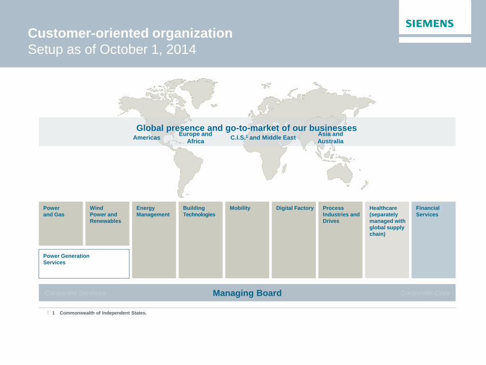
Customer-oriented organization
Setup as of October 1, 2014
Global presence and go-to-market of our businesses Americas
Europe and
Africa C.I.S.1 and Middle East
Asia and
Australia
Power
and Gas
Wind
Power and
Renewables
Energy
Management
Building
Technologies
Mobility Digital Factory Process
Industries and
Drives
Power Generation
Services
Corporate Core Corporate Services
Healthcare
(separately
managed with
global supply
chain)
Financial
Services
1 Commonwealth of Independent States.

Power and Gas Division
Organizational structure as of March 15th, 2015
Power and Gas | Steam Turbines Page 3 March 2015
Div
isio
n
Bu
sin
ess
Un
its
B
usin
ess F
ield
s
* Combined heat and power ** Integrated gasification combined cycle *** After closing of acquisition from Rolls-Royce Energy. Regulatory approval pending.
Turbo compressors for
- Oil & Gas
- Industrial applications
Compressor packages incl. drives
Gas turbines
from 100 to
400 MW
Electrical
generators from
25 up to
2,235 MVA
Fuel gasifiers
Industrial gas
turbines from
5 to 50 MW
Aero derivative
gas turbines
from 4 to
64 MW***
Steam turbines
from 45 kW to
1,900 MW
Steam turbines
for industrial
applications &
power
generation
50 HZ and
60 HZ Gas
turbine power
plant solutions
CHP*
IGCC**
Repowering
Integrated solar
combined cycle
Instrumentation
and Electrical Compressors
Large Gas
Turbines,
Generators
Distributed
Generation Steam Turbines
Energy
Solutions
Control
solutions
Electrical
solutions
Energy
management
solutions
Solutions for
distributed and
hybrid power
generation
Power and Gas
CEO Willibald Meixner
(PG GT) (PG DG) (PG SU) (PG CP) (PG ES) (PG IE)
Acquisition ongoing, subject to authorities approval
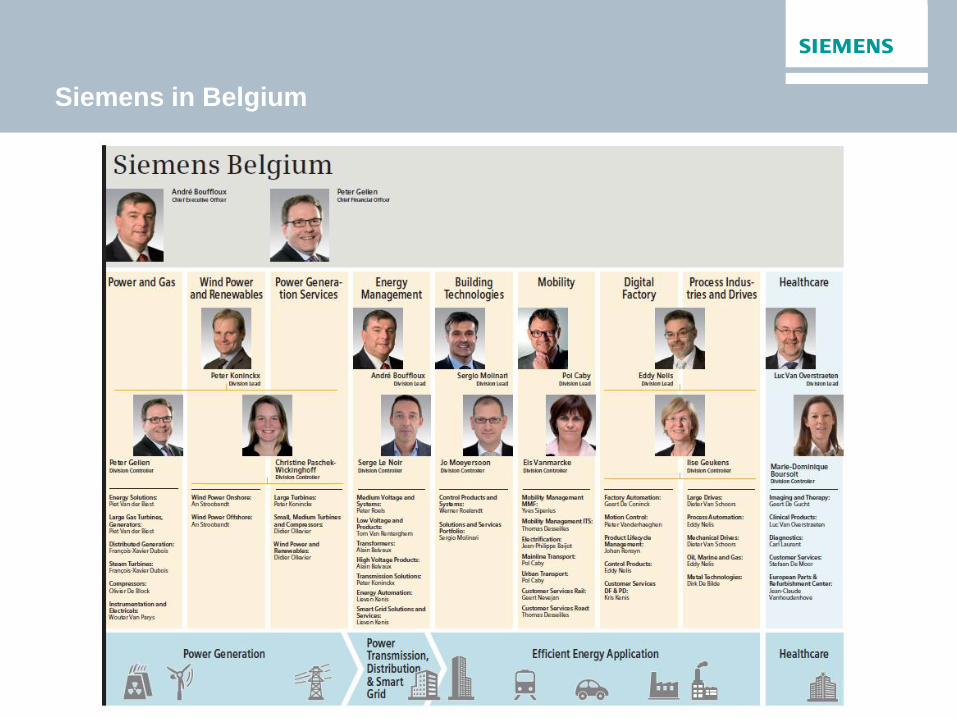
Siemens in Belgium

Siemens Belgium Lead Country for BeLux,
Maghreb and West & Central Africa
Benin
Burkina Faso
Burundi
Cameroon
Central African Republic
Chad
Congo
Congo, the Democratic Republic of the
Côte d'Ivoire
Equatorial Guinea
Gabon
Western Sahara
Belgium
Luxembourg
Morocco
Algeria
Tunisia
Assigned Countries without own setup
Assigned Countries
Gambia
Guinea
Guinea Bissau
Liberia
Mali
Mauritania
Niger
Rwanda
Senegal
Sierra Leone
Togo

Employees in R&D Ranking in patent applications
R&D spending as % of revenue Partnerships
28,800
13,200
15,600
R&D employees
worldwide
R&D employees
in Germany
R&D employees in approximately
30 other countries worldwide
FY 2014
€4.1 billion
5.7 5.5
FY 2014 FY 2013
Siemens currently holds approximately 56,100 patents
granted worldwide
partnerships with universities, research
institutes and other organizations around the
world 1,000
No. 4 Germany
(2013) No. 13 USA
(2013)
No. 2 Europe
(2013)
…by continuous investment in innovation
Our dedication is to grow your business
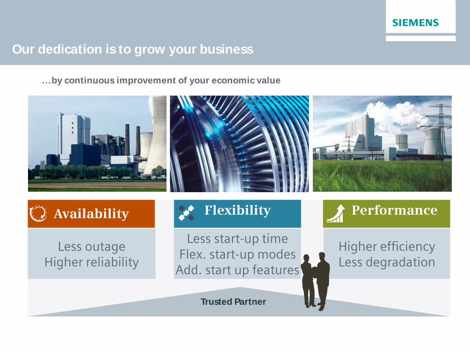
Our dedication is to grow your business
Availability Flexibility Performance
Less outage Higher reliability
Less start-up time Flex. start-up modes
Add. start up features
Higher efficiency Less degradation
Trusted Partner
…by continuous improvement of your economic value
Power and Gas | Steam Turbines Page 8
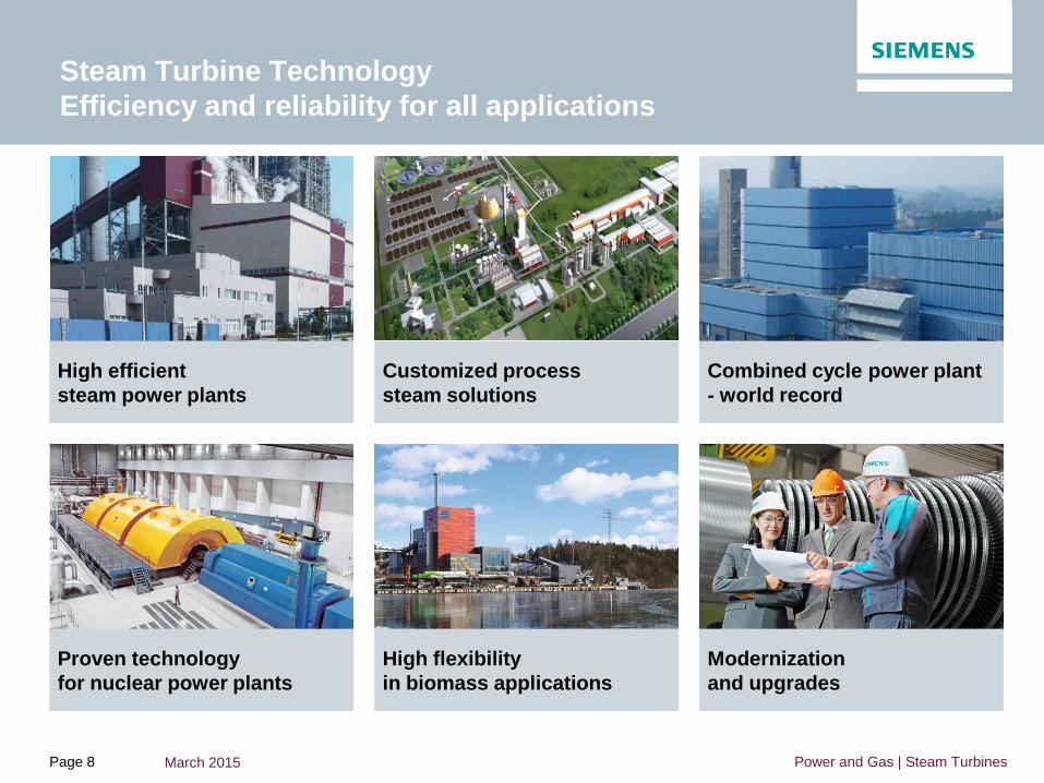
Steam Turbine Technology
Efficiency and reliability for all applications
Proven technology
for nuclear power plants
High flexibility
in biomass applications
Modernization
and upgrades
High efficient
steam power plants
Customized process
steam solutions
Combined cycle power plant
- world record
March 2015

Concentrated Solar Power: turbine applications
Solar Power Tower
(Water / Direct Steam)
3 plants, 392 MW(e) in total
3 x Siemens SST-900
Power output: 3 x123 MW(e)
Inlet steam pressure: 160 bar
Inlet steam temperature: 540°C
IVANPAH SOLAR POWER
COMPLEX,
California, USA
Parabolic trough (Oil)
2 plants, 50 MW(e) each
2 x Siemens SST-700
Power output: 2 x 50 MW(e)
Inlet steam pressure: 100 bar
Inlet steam temperature: 377°C
ANDASOL 1 + 2,
Granada, Spain
Concentrated Solar Power
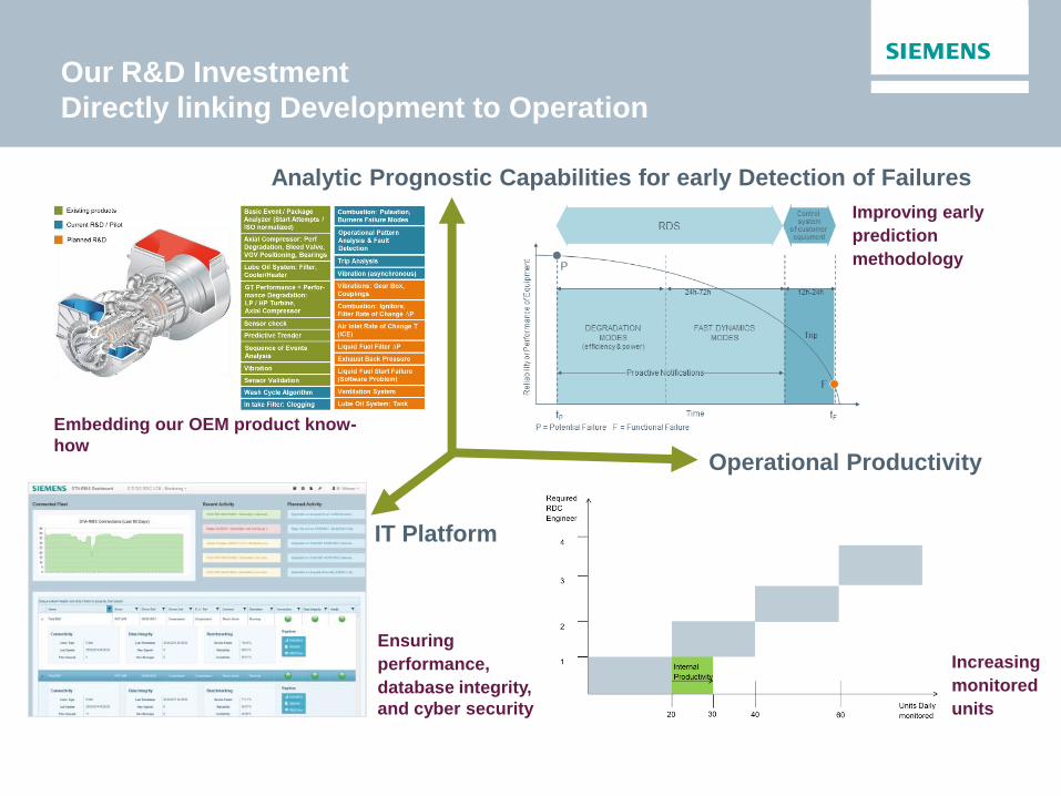
Our R&D Investment
Directly linking Development to Operation
Operational Productivity
Increasing
monitored
units
IT Platform
Ensuring
performance,
database integrity,
and cyber security
Analytic Prognostic Capabilities for early Detection of Failures
Embedding our OEM product know-
how
Improving early
prediction
methodology

The Power Generation Sales team
POWER & GAS
(PG)
Head: Peter Koninckx
STEAM & GAS TURBINES
(PG SU / DG)
Head: Francois-Xavier Dubois
Sales: - Wim Van Den Mosselaer (BeLux)
INTRUMENTATION & ELECTRICITY (PG IE)
Head: Wouter Van Parijs
Sales: - Hugo Cautaers
- Gauthier Cogels
ENERGY SOLUTIONS
(PG ES)
Head: Piet Van der Biest
POWER GENERATION SERVICES
(PS)
Head: Peter Koninckx
POWER & GAS (PS PG)
Head: Peter Koninckx
Sales: Johan Schautteet
WIND POWER (PS WP)
Head: Didier Ollevier
DISTRIBUTED GEN & COMPRESSORS (PS DGC)
Head: Didier Ollevier
Sales: - Pierre Dal
- Stef Lauwers
- Koen Van Cutsem
- Wim Van Den Mosselaer
WIND POWER & RENEWABLES
(WP)
Head: Peter Koninckx
ONSHORE
(WP ON)
Head: An Stroobandt
OFFSHORE
(WP OF)
Head: An Stroobandt
Business Development Africa: Olivier De Block
Business Development & Sales WC Africa: Habib Ben Farhat
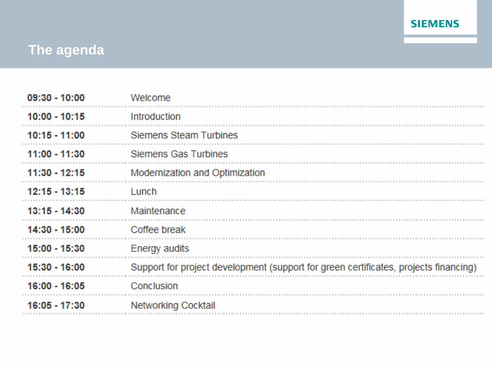
The agenda

Questions?
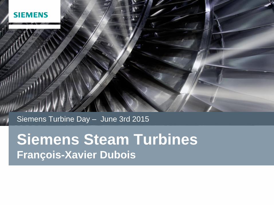
Siemens Steam Turbines François-Xavier Dubois
Siemens Turbine Day – June 3rd 2015

Steam Turbines
Alstom Industrial Turbines
Industrial Steam Turbines
Large Steam Turbines
2004 ABB AEG Kanis
ASEA STAL 1990 1980
1960 1970 1990 1980 2000 20th century
Görlitzer Maschinenbau-Anstalt
1992
Demag Delaval 2002
KK&K 2007
AEG Steam Turbines
1969
2010
Siemens Steam Turbines
Inheritage of 100 years of technology

Siemens Steam Turbines
World wide presence
Manufacturing
Global Steam Turbine Organization
Finspong
16 locations
~ 6.000 employees
Vadodara
Cilegon
Gurgaon
Huludao
Bandung
Charlotte
Jundiai
Orlando
Budapest
Brno
Newcastle
Erlangen
Muelheim
Frankenthal
Goerlitz/ Nuremberg
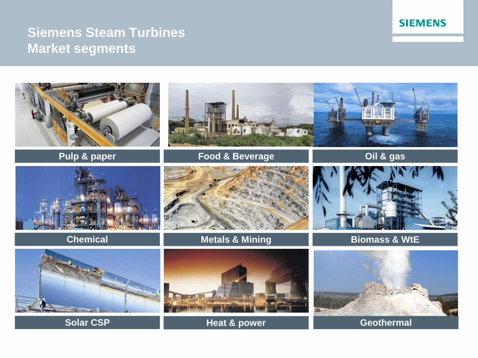
Pulp & paper
Chemical
Oil & gas
Biomass & WtE
Solar CSP
Food & Beverage
Metals & Mining
Heat & power Geothermal
Siemens Steam Turbines
Market segments

Steam Turbines Portfolio
Products for all applications
12 MW
8 MW
0.75 MW
0.3 MW
7 MW
8.5 MW
1,200 MW
1,900 MW
1,900 MW
Po
wer
Ge
ne
rati
on
(5
0/6
0 H
z)
Ind
us
tria
l G
en
era
tio
n
Co
mp
act
ap
p.
SST-6000
SST-900
SST-8000
SST-9000
SST-5000
SST-4000*
SST-3000
SST-700
SST-800
SST-600
SST-500
SST-400
SST-300
SST-200
SST-150
SST-111
SST-110
SST-100
SST-070
SST-050
SST-040
750 MW
250 MW
250 MW
175 MW
380 MW
50 MW
10 MW
20 MW
100 MW
65 MW
250 MW
150 MW
*) currently no development
Single stage
Frankenthal
Multi stage
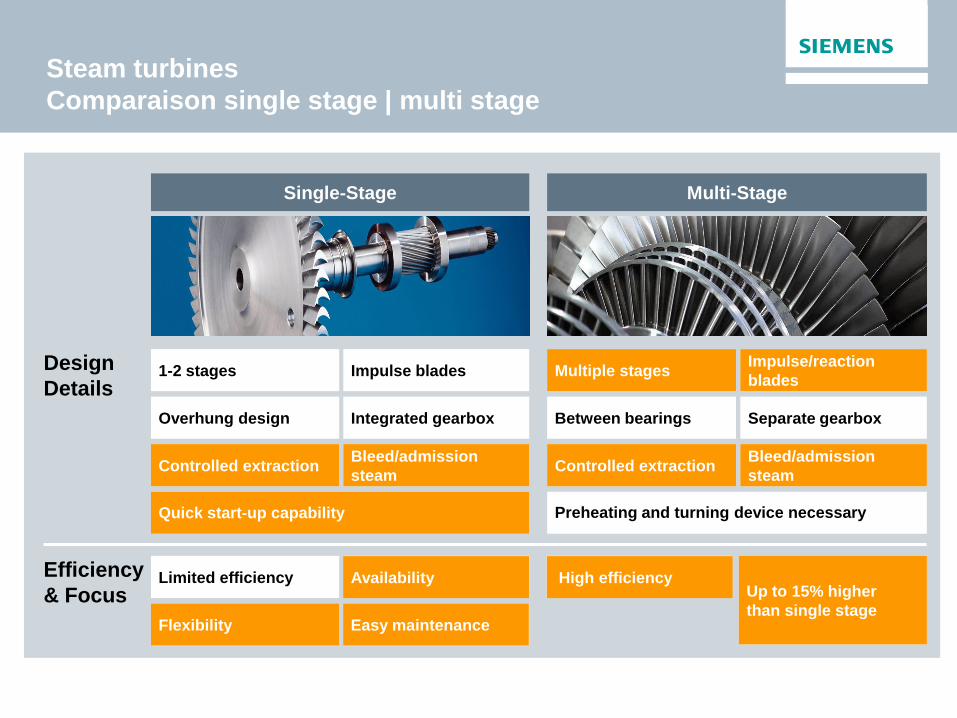
Steam turbines
Comparaison single stage | multi stage
Design
Details
Efficiency
& Focus
Single-Stage Multi-Stage
1-2 stages Impulse blades
Overhung design Integrated gearbox
Controlled extraction Bleed/admission
steam
Quick start-up capability
Limited efficiency Availability
flexibility Easy maintenance
Multiple stages Impulse/reaction
blades
Between bearings Separate gearbox
Controlled extraction Bleed/admission
steam
Preheating and turning device necessary
Up to 15% higher
than single stage
High efficiency
Controlled extraction Bleed/admission
steam
Quick start-up capability
Multiple stages Impulse/reaction
blades
Controlled extraction Bleed/admission
steam
Availability
Flexibility Easy maintenance
Up to 15% higher
than single stage
High efficiency

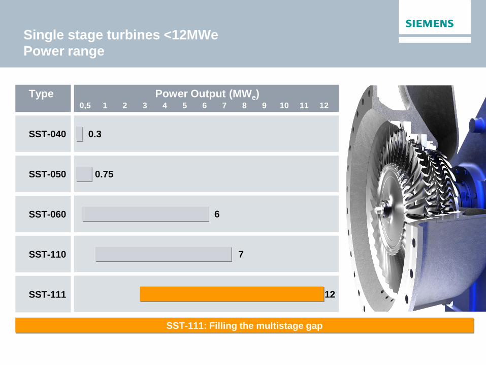
Single stage turbines <12MWe
Nozzle group control
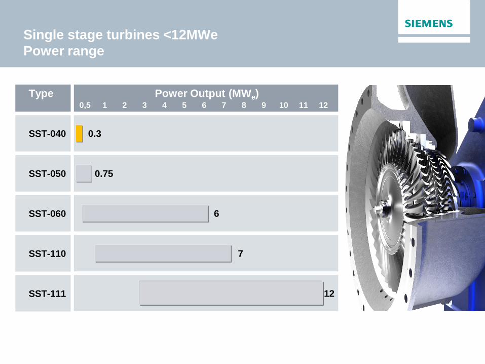
Single stage turbines <12MWe
Power range
SST-040 0.3
SST-111 12
SST-050 0.75
SST-060 6
SST-110 7
Type Power Output (MWe) 10 1 2 3 4 5 6 7 8 9 0,5 12 11
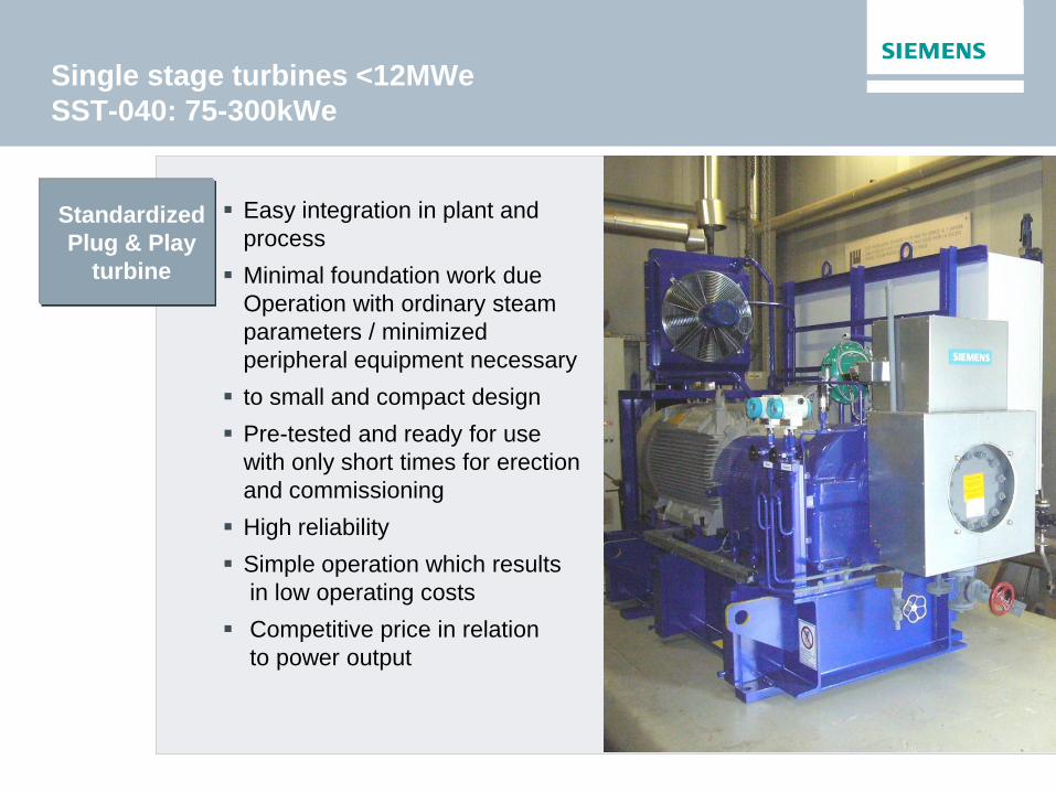
Easy integration in plant and
process
Minimal foundation work due
Operation with ordinary steam
parameters / minimized
peripheral equipment necessary
to small and compact design
Pre-tested and ready for use
with only short times for erection
and commissioning
High reliability
Simple operation which results
in low operating costs
Competitive price in relation
to power output
Standardized
Plug & Play
turbine
Single stage turbines <12MWe
SST-040: 75-300kWe

Single stage turbines <12MWe
SST-040: 75-300kWe

Biomass wood CHP: Mini turbine 300kWe
Installation:
• Wood pallets manufacturer.
• Waste wood from production burned in boiler
to produce steam for:
dryers
building heating/cooling (absorption chiller)
• Mini steam turbine: 265 kWe
Advantages
• reliable
• plug & play design short on site works
• compact solution
PBT < 2 years
Live steam
28bara 245°C
3,4T/h
1bara
265 kWe
Single stage turbines <12MWe
SST-040: key project in Belgium: Trigeneration
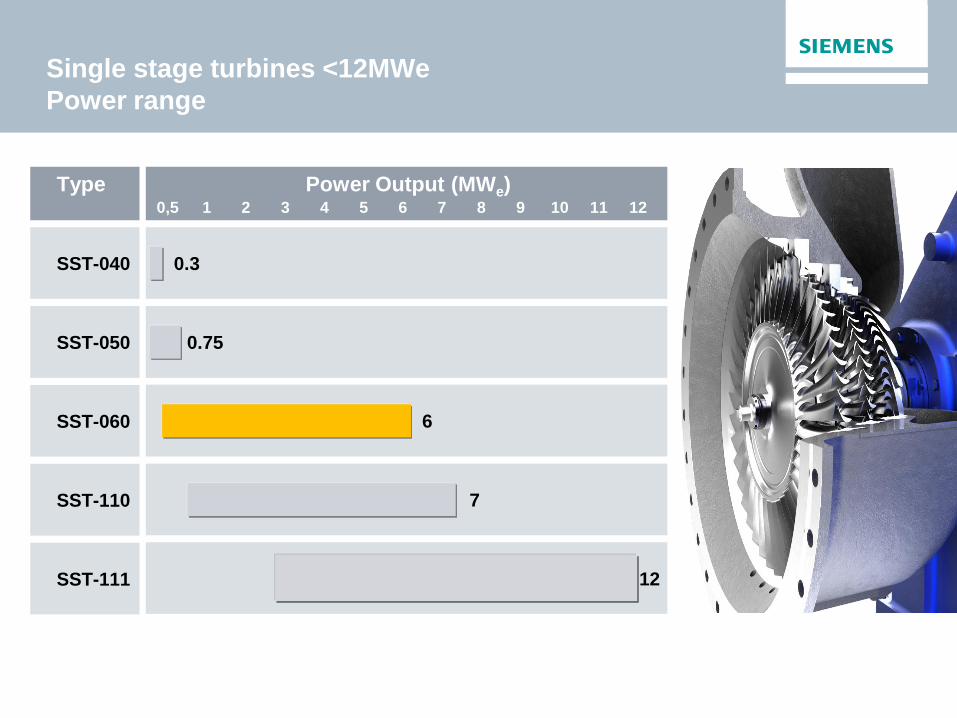
Single stage turbines <12MWe
Power range
SST-040 0.3
SST-111 12
SST-050 0.75
SST-060 6
SST-110 7
Type Power Output (MWe) 10 1 2 3 4 5 6 7 8 9 0,5 12 11
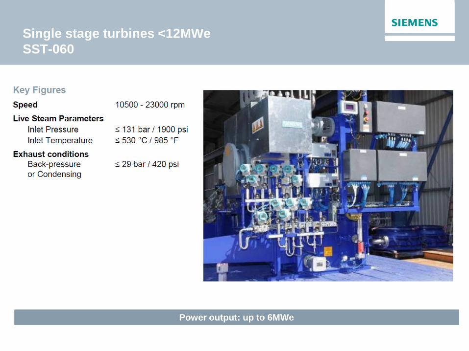
Power output: up to 6MWe
Single stage turbines <12MWe
SST-060
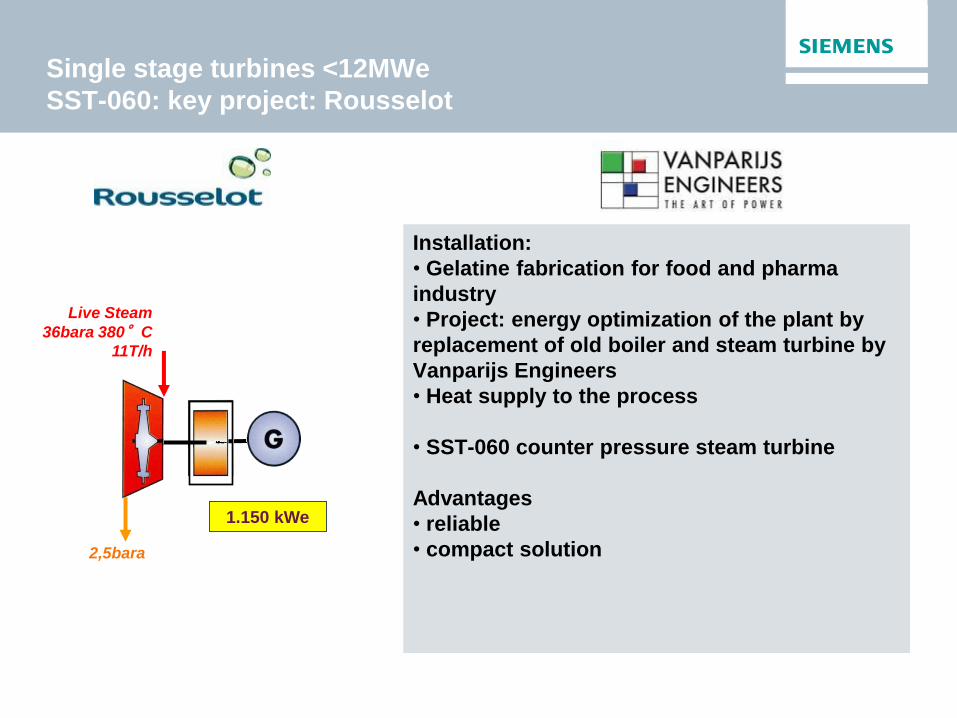
Single stage turbines <12MWe
SST-060: key project: Rousselot
1.150 kWe
Live Steam
36bara 380°C
11T/h
2,5bara
Installation:
• Gelatine fabrication for food and pharma
industry
• Project: energy optimization of the plant by
replacement of old boiler and steam turbine by
Vanparijs Engineers
• Heat supply to the process
• SST-060 counter pressure steam turbine
Advantages
• reliable
• compact solution

Single stage turbines <12MWe
Power range
SST-040 0.3
SST-111 12
SST-050 0.75
SST-060 6
SST-110 7
Type Power Output (MWe) 10 1 2 3 4 5 6 7 8 9 0,5 12 11
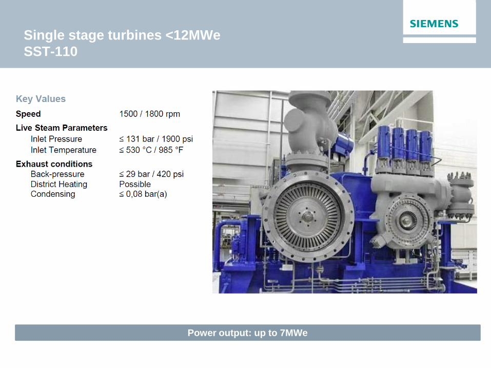
Power output: up to 7MWe
Single stage turbines <12MWe
SST-110
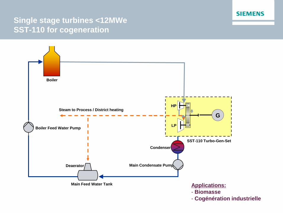
Boiler
Boiler Feed Water Pump
Main Condensate Pump
Steam to Process / District heating
Main Feed Water Tank
Deaerator
HP
G
LP
SST-110 Turbo-Gen-Set
Condenser
Applications:
- Biomasse
- Cogénération industrielle
Single stage turbines <12MWe
SST-110 for cogeneration
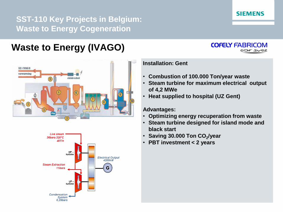
Waste to Energy (IVAGO)
Installation: Gent
• Combustion of 100.000 Ton/year waste
• Steam turbine for maximum electrical output
of 4,2 MWe
• Heat supplied to hospital (UZ Gent)
Advantages:
• Optimizing energy recuperation from waste
• Steam turbine designed for island mode and
black start
• Saving 30.000 Ton CO2/year
• PBT investment < 2 years
SST-110 Key Projects in Belgium:
Waste to Energy Cogeneration
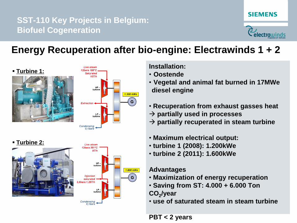
Energy Recuperation after bio-engine: Electrawinds 1 + 2
Installation:
• Oostende
• Vegetal and animal fat burned in 17MWe
diesel engine
• Recuperation from exhaust gasses heat
partially used in processes
partially recuperated in steam turbine
• Maximum electrical output:
• turbine 1 (2008): 1.200kWe
• turbine 2 (2011): 1.600kWe
Advantages
• Maximization of energy recuperation
• Saving from ST: 4.000 + 6.000 Ton
CO2/year
• use of saturated steam in steam turbine
PBT < 2 years
Turbine 1:
Turbine 2:
SST-110 Key Projects in Belgium:
Biofuel Cogeneration

Installation: Liège
• Combustion of 16.300 T/y wood
pellets
• Steam turbine for maximum
electrical output of 2,6 MWe
• Heat supplied to University (ULG)
and hospital.
Advantages:
• Saving 10.000 Ton CO2/year
Reduction of 2/3 of CO2
emissions of the district heating
plant, 1/3 of total Ulg emissions
• Saving 10.000 Ton CO2/year
• Cash flow from green certificates
Sart Tilman ULG biomass plant
SST-110 Key Projects in Belgium:
Biomass Cogeneration
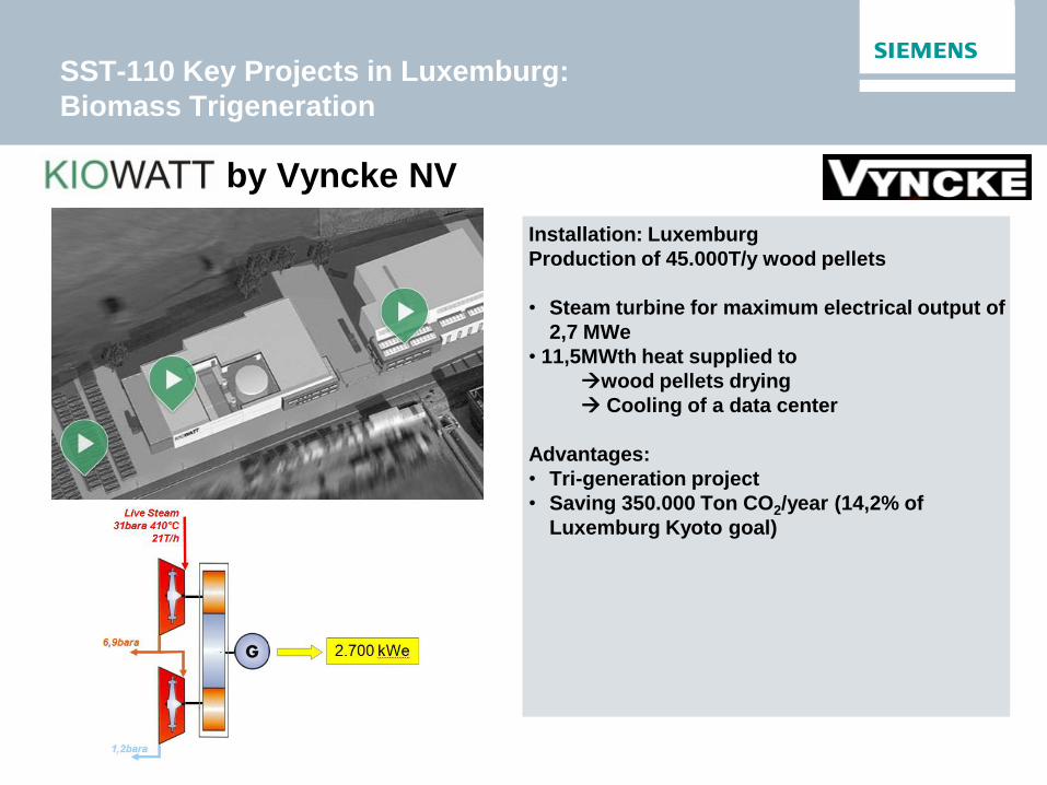
Recybois by Vyncke NV
Installation: Luxemburg
Production of 45.000T/y wood pellets
• Steam turbine for maximum electrical output of
2,7 MWe
• 11,5MWth heat supplied to
wood pellets drying
Cooling of a data center
Advantages:
• Tri-generation project
• Saving 350.000 Ton CO2/year (14,2% of
Luxemburg Kyoto goal)
SST-110 Key Projects in Luxemburg:
Biomass Trigeneration
Single stage turbines <12MWe
Power range
SST-040 0.3
SST-111 12
SST-050 0.75
SST-060 6
SST-110 7
Type Power Output (MWe) 10 1 2 3 4 5 6 7 8 9 0,5 12 11
SST-111: Filling the multistage gap

The best compromise for power
generation from 5 to 12MWe
Availability Flexibility
High efficiency on multi stage level
Multiple stages Impulse/reaction
blades
Controlled extraction Bleed/admission
steam
Quick start-up
capability Easy maintenance
Availability Flexibility
High efficiency on multi stage level
Multiple stages Impulse/reaction
blades
Controlled extraction Bleed/admission
steam
Quick start-up
capability Easy maintenance
Single stage turbines <12MWe
SST-111: hybrid single/multistage
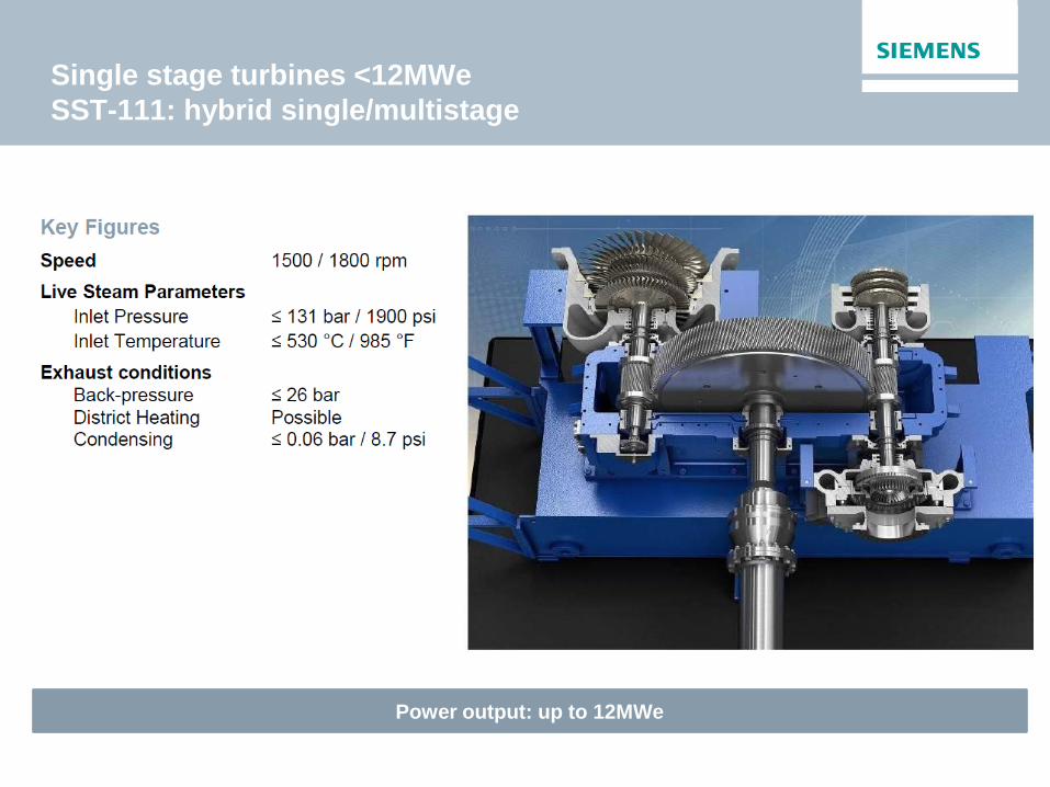
Single stage turbines <12MWe
SST-111: hybrid single/multistage
Power output: up to 12MWe

Biomass (2 extract.)
Single stage turbines <12MWe
SST-111: biomass application
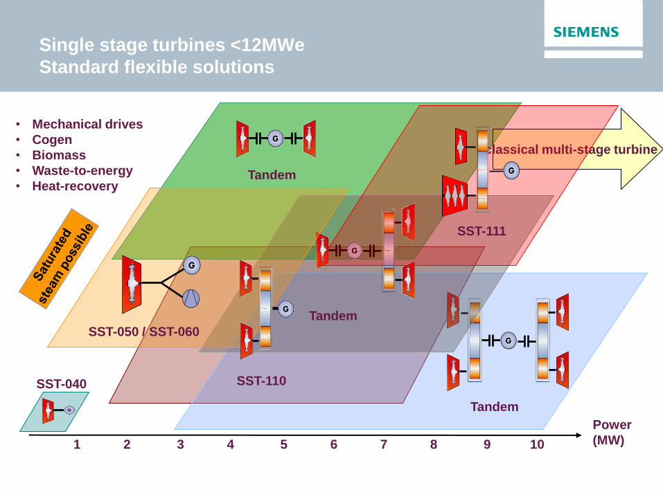
Tandem
Tandem
Power
(MW)
Tandem
1 2 3 4 5 6 7 8 9 10
classical multi-stage turbine
• Mechanical drives
• Cogen
• Biomass
• Waste-to-energy
• Heat-recovery
SST-050 / SST-060
SST-110 SST-040
SST-111
Single stage turbines <12MWe
Standard flexible solutions
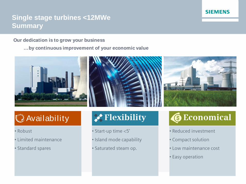
Availability Flexibility Economical
• Robust
• Limited maintenance
• Standard spares
• Start-up time <5’
• Island mode capability
• Saturated steam op.
• Reduced investment
• Compact solution
• Low maintenance cost
• Easy operation
…by continuous improvement of your economic value
Our dedication is to grow your business
Single stage turbines <12MWe
Summary

Steam Turbines Portfolio
Products for all applications
12 MW
8 MW
0.75 MW
0.3 MW
7 MW
8.5 MW
1,200 MW
1,900 MW
1,900 MW
Po
wer
Ge
ne
rati
on
(5
0/6
0 H
z)
Ind
us
tria
l G
en
era
tio
n
Co
mp
act
ap
p.
SST-6000
SST-900
SST-8000
SST-9000
SST-5000
SST-4000*
SST-3000
SST-700
SST-800
SST-600
SST-500
SST-400
SST-300
SST-200
SST-150
SST-111
SST-110
SST-100
SST-070
SST-050
SST-040
750 MW
250 MW
250 MW
175 MW
380 MW
50 MW
10 MW
20 MW
100 MW
65 MW
250 MW
150 MW
*) currently no development
Single stage
Frankenthal
Multi stage
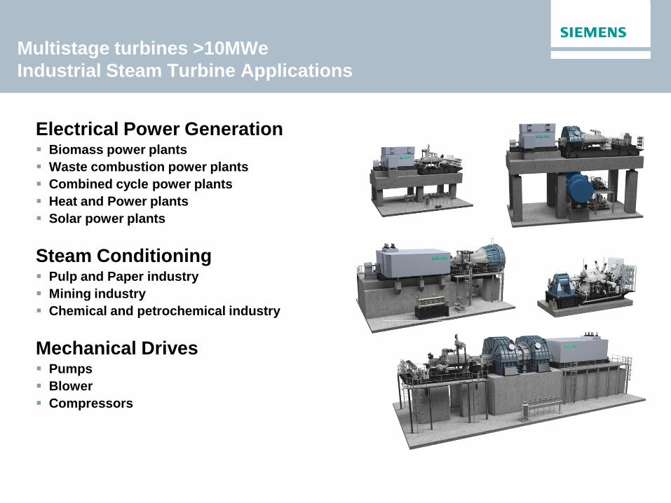
Multistage turbines >10MWe
Industrial Steam Turbine Applications
Electrical Power Generation Biomass power plants
Waste combustion power plants
Combined cycle power plants
Heat and Power plants
Solar power plants
Steam Conditioning Pulp and Paper industry
Mining industry
Chemical and petrochemical industry
Mechanical Drives Pumps
Blower
Compressors

Steam Turbines
Alstom Industrial Turbines
Industrial Steam Turbines
Large Steam Turbines
2004 ABB AEG Kanis
ASEA STAL 1990 1980
1960 1970 1990 1980 2000 20th century
Görlitzer Maschinenbau-Anstalt
1992
Demag Delaval 2002
KK&K 2007
AEG Steam Turbines
1969
2010
Siemens Steam Turbines
Inheritage of 100 years of technology

Multistage turbines >10MWe
Enhanced Platform Motivation
External requirements
High degree of
flexibility to realize
optimal turbine
solutions according
customer needs
Optimized start-up time
Number of extractions
Increased efficiency
Improved economical
solutions
Standard customizable
installation
arrangements
Internal drivers
Acquisition history led to
overlap in product
portfolio and power range
Huge variation of Steam
Turbine Types incl. the
maintenance of the tools
Implementation of
advantages of all families
into one product
Incorporation of new state
of the art features
Enhanced Platform
Multistage turbines >10MWe
Enhanced Platform Building Block Approach
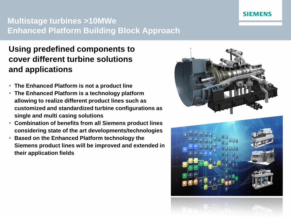
Using predefined components to
cover different turbine solutions
and applications
The Enhanced Platform is not a product line
The Enhanced Platform is a technology platform
allowing to realize different product lines such as
customized and standardized turbine configurations as
single and multi casing solutions
Combination of benefits from all Siemens product lines
considering state of the art developments/technologies
Based on the Enhanced Platform technology the
Siemens product lines will be improved and extended in
their application fields

Multistage turbines >10MWe
Enhanced Platform Modularization
Maximum flexibility due to standardization at sub-part level
Steam
Admission
Section
Intermediate
Section
Exhaust
Section

Multistage turbines >10MWe
Enhanced Platform Key Parameters
Power output 5 – 250 MW
Speed 3000 – 18000 rpm
Live steam
Inlet pressure/temp ≤ 165 bar / ≤ 565 ºC
Inlet pressure/temp ≤ 2393 psi / ≤ 1049 ºF
Controlled extractions (up to 2)
Pressure, ext. valve ≤ 72 bar / 1044 psi
Pressure, int. valve ≤ 55 bar / 798 psi
Temperature ≤ 480 ºC / 895 ºF
Bleeds (up to 6) ≤ 85 bar / 1233 psi
Exhaust conditions
Back-pressure ≤ 80 bar / 1160 psi
Condensing ≤ 1.0 bar / 15 psi
District heating ≤ 3.0 bar / 43 psi
Multistage turbines >10MWe
Enhanced Platform Exhaust Constructions
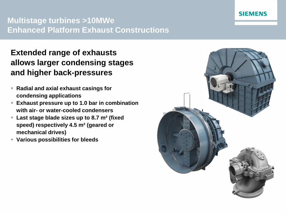
Extended range of exhausts
allows larger condensing stages
and higher back-pressures
Radial and axial exhaust casings for
condensing applications
Exhaust pressure up to 1.0 bar in combination
with air- or water-cooled condensers
Last stage blade sizes up to 8.7 m² (fixed
speed) respectively 4.5 m² (geared or
mechanical drives)
Various possibilities for bleeds

Customer Benefits
Optimized
Performance
Higher steam parameter
Improved design for reduced start-up times
Improved flexibility for optimized customer solutions
Best technology features under common umbrella
Improved efficiency (up to 2 %)
Long life cycle – increased life time
Extensive tested and verified first turbine
Improved CO2 footprint (15 % reduction of CO2 emissions)
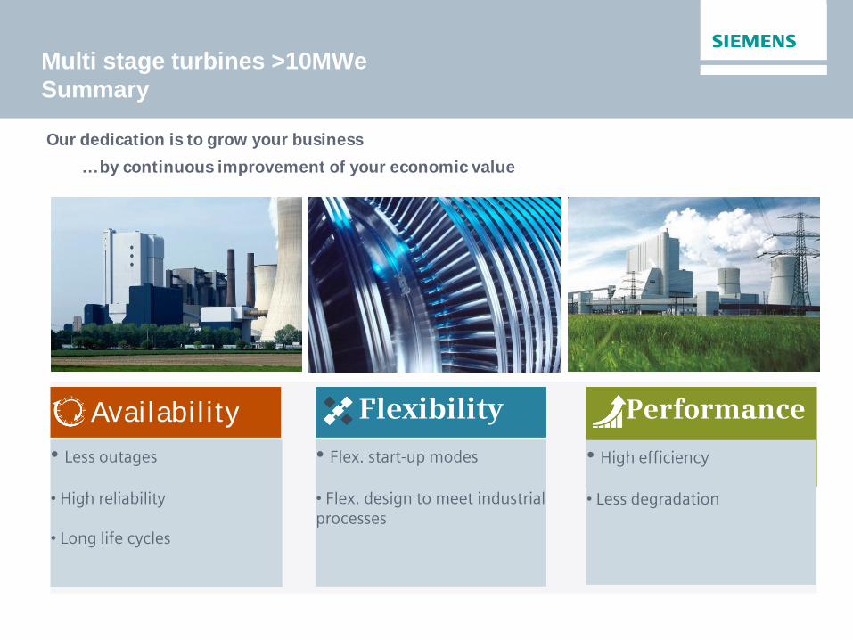
Availability Flexibility Performance
• Less outages
• High reliability
• Long life cycles
• Flex. start-up modes
• Flex. design to meet industrial processes
• High efficiency
• Less degradation
Multi stage turbines >10MWe
Summary
…by continuous improvement of your economic value
Our dedication is to grow your business
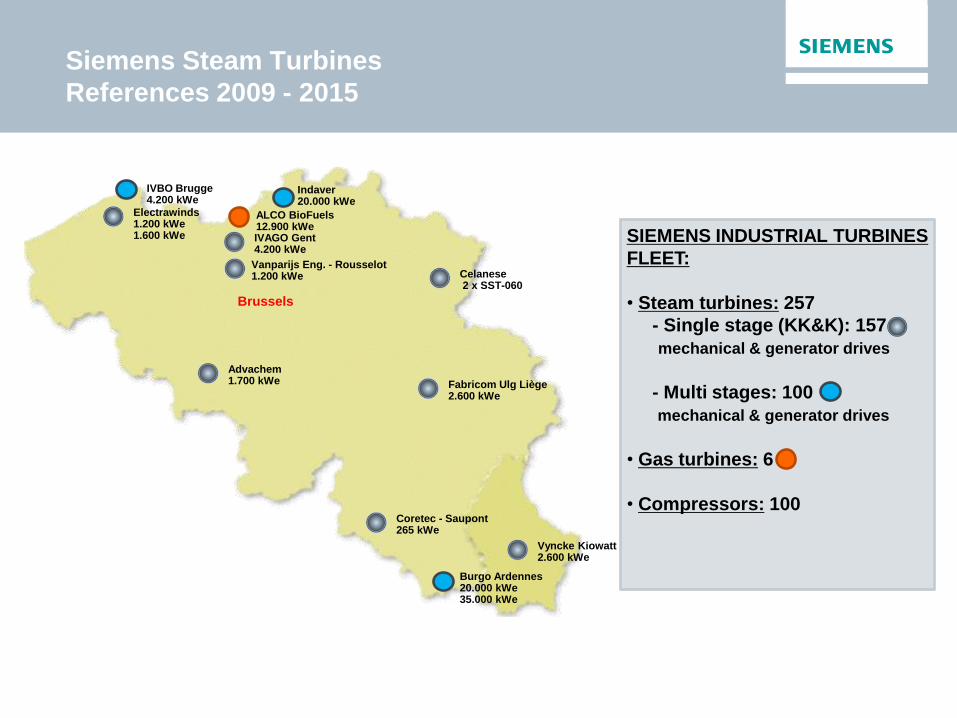
Electrawinds 1.200 kWe 1.600 kWe
Brussels
IVAGO Gent 4.200 kWe
Coretec - Saupont 265 kWe
Burgo Ardennes 20.000 kWe 35.000 kWe
Indaver 20.000 kWe
Fabricom Ulg Liège 2.600 kWe
Advachem 1.700 kWe
SIEMENS INDUSTRIAL TURBINES
FLEET:
• Steam turbines: 257
- Single stage (KK&K): 157
mechanical & generator drives
- Multi stages: 100
mechanical & generator drives
• Gas turbines: 6
• Compressors: 100
Vyncke Kiowatt 2.600 kWe
ALCO BioFuels 12.900 kWe
Celanese 2 x SST-060
IVBO Brugge 4.200 kWe
Siemens Steam Turbines
References 2009 - 2015
Vanparijs Eng. - Rousselot 1.200 kWe
Multistage turbines >10MWe
Key Projects: Cogeneration
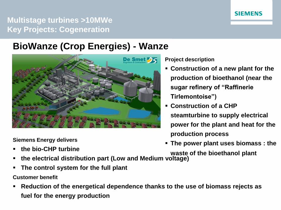
BioWanze (Crop Energies) - Wanze
Siemens Energy delivers
the bio-CHP turbine
the electrical distribution part (Low and Medium voltage)
The control system for the full plant
Customer benefit
Reduction of the energetical dependence thanks to the use of biomass rejects as
fuel for the energy production
Project description
Construction of a new plant for the
production of bioethanol (near the
sugar refinery of “Raffinerie
Tirlemontoise”)
Construction of a CHP
steamturbine to supply electrical
power for the plant and heat for the
production process
The power plant uses biomass : the
waste of the bioethanol plant

Multistage turbines >10MWe
Key Projects: Biomass
Project description
Construction of a new CHP
steamturbine of 30 MW
The installation uses biomass: the wood
waste (bark) produced by Burgo
Burgo Ardennes - Virton
Siemens Energy delivers
the turbo generator
the expert system for the optimization
of the biofuel consumption
Customer benefit
The new turbine produces a supplement of 3,5 MWe with the same heat production
With the same biomass consumption, less energetical dependence
The autoproduction of energy will cover more than 80% of electricity for the mill.
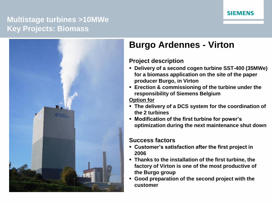
Multistage turbines >10MWe
Key Projects: Biomass
Burgo Ardennes - Virton
Project description Delivery of a second cogen turbine SST-400 (35MWe)
for a biomass application on the site of the paper
producer Burgo, in Virton
Erection & commissioning of the turbine under the
responsibility of Siemens Belgium
Option for
The delivery of a DCS system for the coordination of
the 2 turbines
Modification of the first turbine for power’s
optimization during the next maintenance shut down
Success factors Customer’s satisfaction after the first project in
2006
Thanks to the installation of the first turbine, the
factory of Virton is one of the most productive of
the Burgo group
Good preparation of the second project with the
customer
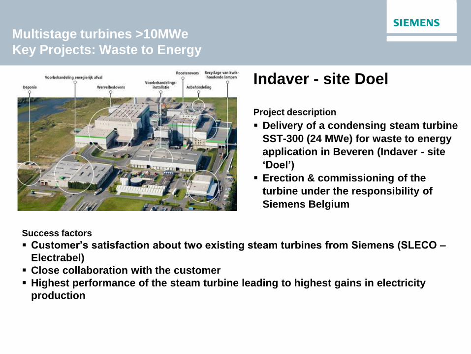
Multistage turbines >10MWe
Key Projects: Waste to Energy
Indaver - site Doel Project description
Delivery of a condensing steam turbine
SST-300 (24 MWe) for waste to energy
application in Beveren (Indaver - site
‘Doel’)
Erection & commissioning of the
turbine under the responsibility of
Siemens Belgium
Success factors
Customer’s satisfaction about two existing steam turbines from Siemens (SLECO –
Electrabel)
Close collaboration with the customer
Highest performance of the steam turbine leading to highest gains in electricity
production

Steam Turbines Portfolio
Products for all applications
12 MW
8 MW
0.75 MW
0.3 MW
7 MW
8.5 MW
1,200 MW
1,900 MW
1,900 MW
Po
wer
Ge
ne
rati
on
(5
0/6
0 H
z)
Ind
us
tria
l G
en
era
tio
n
Co
mp
act
ap
p.
SST-6000
SST-900
SST-8000
SST-9000
SST-5000
SST-4000*
SST-3000
SST-700
SST-800
SST-600
SST-500
SST-400
SST-300
SST-200
SST-150
SST-111
SST-110
SST-100
SST-070
SST-050
SST-040
750 MW
250 MW
250 MW
175 MW
380 MW
50 MW
10 MW
20 MW
100 MW
65 MW
250 MW
150 MW
*) currently no development
Single stage
Frankenthal
Multi stage

Questions?
Siemens Gas Turbines John Roberts
Siemens Turbine Day – June 3rd 2015
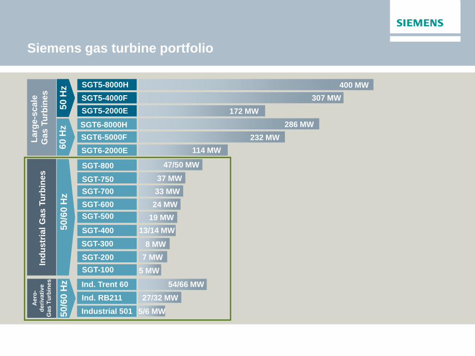
Siemens gas turbine portfolio In
du
str
ial
Gas T
urb
ines
50
Hz SGT5-8000H
SGT5-4000F
SGT5-2000E
307 MW
172 MW
400 MW
SGT6-8000H
114 MW
SGT6-5000F
SGT6-2000E
286 MW
232 MW
60
Hz
La
rge-s
ca
le
Ga
s T
urb
ine
s
50
/60
Hz
47/50 MW
33 MW
24 MW
8 MW
7 MW
SGT-800
5 MW
37 MW
19 MW
13/14 MW
SGT-800
SGT-750
SGT-700
SGT-600
SGT-500
SGT-400
SGT-300
SGT-200
SGT-100
27/32 MW
5/6 MW
54/66 MW Ind. Trent 60
Ind. RB211
Industrial 501
Ae
ro-
de
riva
tive
Ga
s T
urb
ine
s
50
/60
Hz
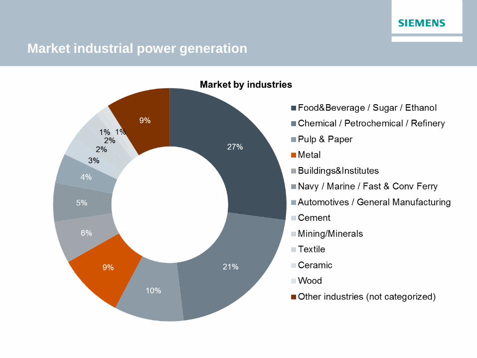
Market industrial power generation
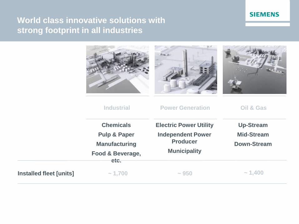
World class innovative solutions with
strong footprint in all industries
Chemicals
Pulp & Paper
Manufacturing
Food & Beverage,
etc.
Electric Power Utility
Independent Power
Producer
Municipality
Installed fleet [units] ~ 1,700 ~ 950
Industrial Power Generation
Up-Stream
Mid-Stream
Down-Stream
Oil & Gas
~ 1,400

Our gas turbine portfolio with complementary
technologies for a broad range of applications
Current gas turbine portfolio
GT model Max. electrical power output (MW)
53 MW
37 MW
33 MW
24 MW
19 MW
13 MW
8 MW
7 MW
5 MW
SGT-800
SGT-750
SGT-700
SGT-600
SGT-500
SGT-400
SGT-300
SGT-200
SGT-100
66 MW
32 MW
6 MW
Ind. Trent 60
Ind. RB211
Industrial 501
Complementary technology strengths
Customers can choose from different technologies in the full output range
Good gas fuel flexibility
Stable proven DLE
systems
Designed for a wide range
of industrial applications
(e.g. combined cycle
power plants)
Main application:
Industrial power generation
Light cores with a
generally
smaller package footprint
Quality level inherited
from aero engines
Designed for high number
of cycles with high single
cycle efficiency Main application:
Offshore production platforms

Technology leader with best gas turbines technology
Industrial gas turbines (IGT’s)
• Significant inno-
vation potential
in reliability, life
cycle, efficiency,
flexibility (via
materials, aero
dynamics,
combustion,
manufacturing,
etc.)
• Combined
technology
know-how to
develop ‘best of
breeds’ future
gas turbines
Application of aero
technology to IGTs:
Improved
competitiveness
through advanced aero
technologies.
Application of industrial
technology to ADGTs:
Improved
competiveness through
industrial techniques
and technologies
Aero-derivative gas turbines (ADGT’s)
Significant innovation potential of combining leading technologies
Combination of leading technologies
• Focus on
ADGT
innovation
• Leverage
industrial
technologies
• Focus on IGT
innovation
• Leverage
aero IP
access

0
25
50
75
100
125
150
175
200
0 5 10 15 20 25 30 35 40 45 50
Power (MWe)
Ste
am
(to
nn
es/h
r) [
12 b
ar
satu
rate
d]
Unfired
Fired
SG
T-1
00
SG
T-3
00
SG
T-4
00
SG
T-5
00
SG
T-6
00
SG
T-7
00
SG
T-8
00
Steam Raising Capabilities for Gas Turbine
Co-Generation Plant
Notes:
1. Steam values are indicative only. Actual values depend on site configuration
2. Firing to 850ºC only. Higher firing is available

DLE Combustion
First DLE unit introduced early ’90’s
Scaled common design
>450 DLE units in service
~20,000,000 DLE running hours
Easy to maintain and service
Ease of assembly and installation
Can Combustor Design
Igniter in each Combustion Can
Wide Fuel Flexibility
CT1 Nozzles
Compressor
Exit Diffuser
Combustion Zone
Pre-Chamber Air
& Fuel Mixing
Zone
Combustion Can
Pilot
Burner
Main Burner
Transition Duct
DLE combustion system
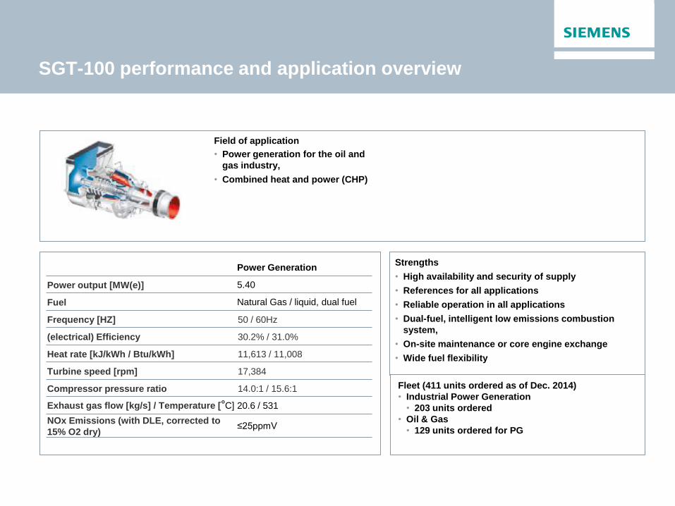
SGT-100 performance and application overview
Power Generation
Power output [MW(e)] 5.40
Fuel Natural Gas / liquid, dual fuel
Frequency [HZ] 50 / 60Hz
(electrical) Efficiency 30.2% / 31.0%
Heat rate [kJ/kWh / Btu/kWh] 11,613 / 11,008
Turbine speed [rpm] 17,384
Compressor pressure ratio 14.0:1 / 15.6:1
Exhaust gas flow [kg/s] / Temperature [ºC] 20.6 / 531
NOx Emissions (with DLE, corrected to
15% O2 dry) ≤25ppmV
Field of application
• Power generation for the oil and
gas industry,
• Combined heat and power (CHP)
Strengths
• High availability and security of supply
• References for all applications
• Reliable operation in all applications
• Dual-fuel, intelligent low emissions combustion
system,
• On-site maintenance or core engine exchange
• Wide fuel flexibility
Fleet (411 units ordered as of Dec. 2014)
• Industrial Power Generation
• 203 units ordered
• Oil & Gas
• 129 units ordered for PG
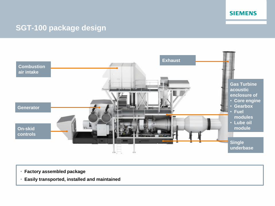
SGT-100 package design
• Factory assembled package
• Easily transported, installed and maintained
Combustion
air intake
On-skid
controls
Generator
Gas Turbine
acoustic
enclosure of
• Core engine
• Gearbox
• Fuel
modules
• Lube oil
module
Exhaust
Single
underbase
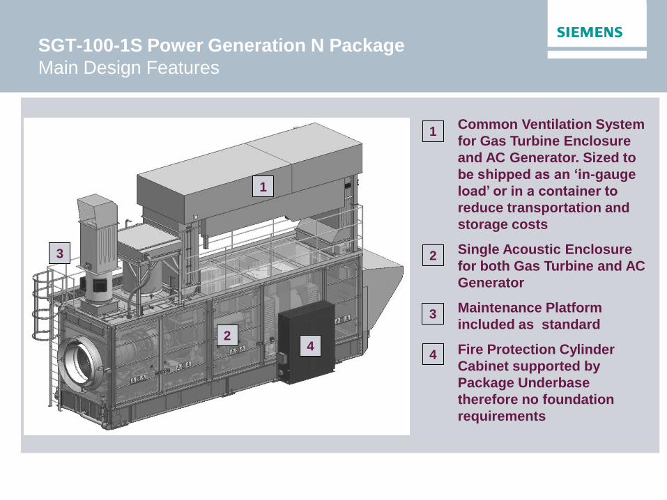
SGT-100-1S Power Generation N Package
Main Design Features
4
1
3
Common Ventilation System
for Gas Turbine Enclosure
and AC Generator. Sized to
be shipped as an ‘in-gauge
load’ or in a container to
reduce transportation and
storage costs
Single Acoustic Enclosure
for both Gas Turbine and AC
Generator
Maintenance Platform
included as standard
Fire Protection Cylinder
Cabinet supported by
Package Underbase
therefore no foundation
requirements
2
1
2
3
4

SGT-100-1S Power Generation N Package
Main Design Features
Combined UCP, GCP and
DC distribution in one
junction box
AC Generator with through
flow ventilation cooling
configuration
Oil Coalescer mounted
within the enclosure –
Reduces number of site lifts
Package Junction Box for
site cabling – Reduces I&C
time
Bundled main customer
mechanical interfaces, page
6
Reduced amount of external
piping and wiring – Reduces
I&C time
Roof mounted Lube Oil
Cooler
5
6
7
8
9
5
6
7
8
10
11
10 9
11

SGT-300 performance and application overview
Field of application
Power Generation
Power output [MW(e)] 7.90
Fuel
Natural gas / liquid fuel / dual
fuel and other fuels capability on
request
Frequency [Hz] 50/60
(electrical) Efficiency 30.6%
Heat rate [kJ/kWh / Btu/kWh] 11,773 / 11,158
Turbine speed [rpm] 14,010
Compressor pressure ratio 13.7:1
Exhaust gas flow [kg/s] / Temperature [ºC] 30.2 / 542
NOx Emissions (with DLE, corrected to
15% O2 dry) ≤15 ppmV
Strengths
• High availability record in PG
• References for all PG applications
• Gas fuel flexibility with intelligent combustion and
low emissions
• High CHP efficiency for high flow/quality steam
applications
• On-site maintenance or core exchange
• Power generation for the oil and
gas industry,
• Combined heat and power (CHP)
Fleet (143 units ordered as of Dec. 2014)
• Industrial Power Generation
• 63 units ordered
• Oil & Gas
• 78 units ordered for PG
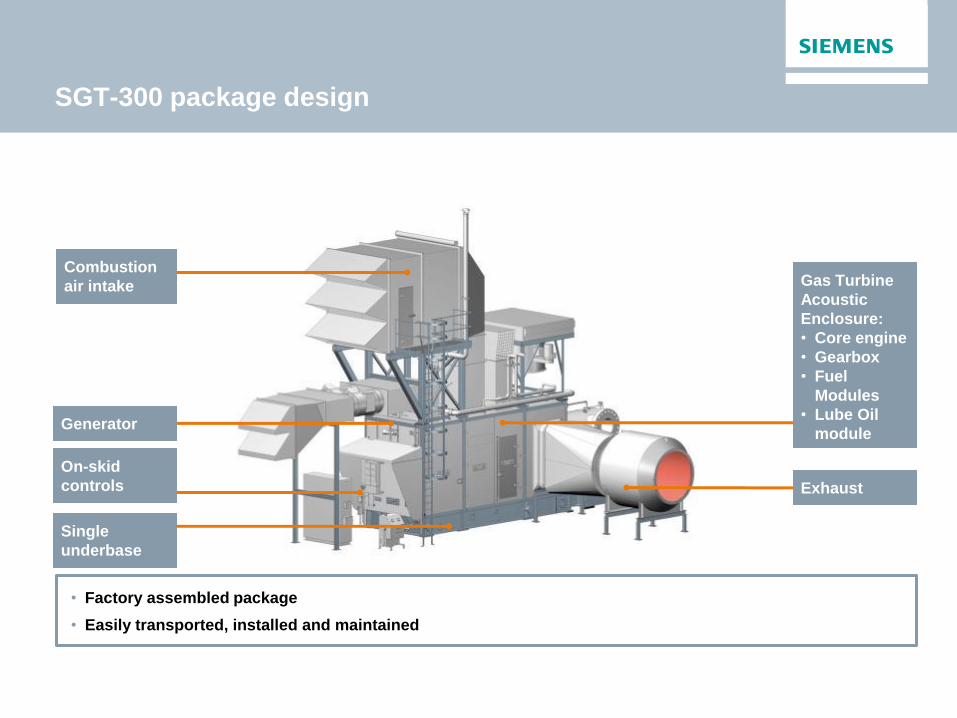
SGT-300 package design
• Factory assembled package
• Easily transported, installed and maintained
Combustion
air intake
On-skid
controls
Generator
Gas Turbine
Acoustic
Enclosure:
• Core engine
• Gearbox
• Fuel
Modules
• Lube Oil
module
Single
underbase
Exhaust

SGT-400 performance and application overview
Field of application
• Pumping and compressor apps
• Power generation for the O&G industry
• Simple / combined cycle applications
• Combined heat and power (CHP)
Power Generation
Power output [MW(e)] 13.40 14.33
Fuel Natural gas / dual fuel and other
fuels capability on request
Frequency [Hz] 50 / 60
(electrical) Efficiency 34.8% / 35.4%
Heat rate [kJ/kWh ] 10,355 / 10,178
Turbine speed [rpm] 9,500
Compressor pressure ratio 16.8:1 / 18.9:1
Exhaust gas flow [kg/s] / Temperature [ºC] 39.4 / 555
44.3 / 540
NOx Emissions (with DLE, corrected to
15% O2 dry) ≤15 ppmV
Strengths
• High availability
• Good O&G reference list
• High simple cycle efficiency
• High CHP efficiency
• Wide gas fuel flexibility including Coke Oven Gas
Fleet (304 units as of Dec. 2014)
• Industrial Power Generation
• 66 units ordered
• Oil & Gas
• 97 units ordered for PG

SGT-400 package design for O&G PG
Air intake
Controls Core Engine
AC-generator
Exhaust
Underbase
Auxiliary systems
Main gear
Common modular package design concept for Power Generation
Pre-designed options, easily transported, installed and maintained at site
Acoustic treatment to reduce noise levels to 85 dB(A) as standard (lower levels available as options)

SGT-400 Power Generation Mechanical Drive
SGT-100 Mechanical Drive
SGT-300 Power Generation
Standard Modules Generic Packages
SGT-100 Power Generation O&G Power Generation
SGT Gas Turbine Family
Package Technology Platform
First Build
2008
2010
2011
2012
SGT-300 Mechanical Drive
2013
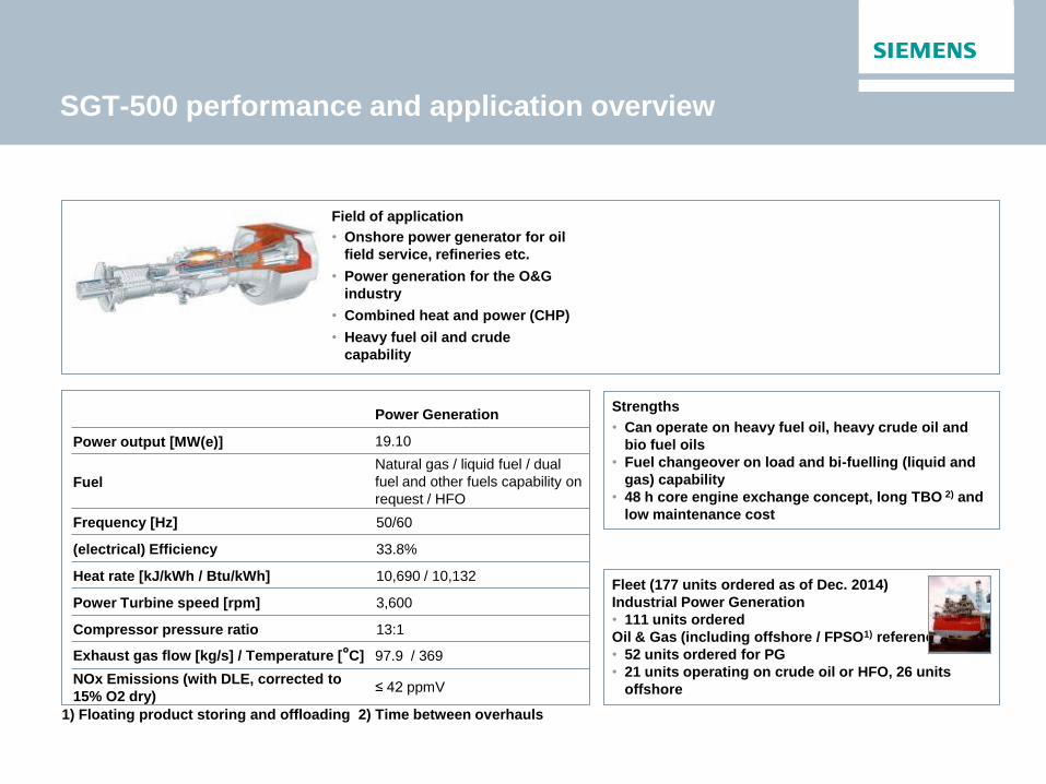
Power Generation
Power output [MW(e)] 19.10
Fuel
Natural gas / liquid fuel / dual
fuel and other fuels capability on
request / HFO
Frequency [Hz] 50/60
(electrical) Efficiency 33.8%
Heat rate [kJ/kWh / Btu/kWh] 10,690 / 10,132
Power Turbine speed [rpm] 3,600
Compressor pressure ratio 13:1
Exhaust gas flow [kg/s] / Temperature [ºC] 97.9 / 369
NOx Emissions (with DLE, corrected to
15% O2 dry) ≤ 42 ppmV
SGT-500 performance and application overview
Field of application
• Onshore power generator for oil
field service, refineries etc.
• Power generation for the O&G
industry
• Combined heat and power (CHP)
• Heavy fuel oil and crude
capability
Fleet (177 units ordered as of Dec. 2014)
Industrial Power Generation
• 111 units ordered
Oil & Gas (including offshore / FPSO1) references)
• 52 units ordered for PG
• 21 units operating on crude oil or HFO, 26 units
offshore
Strengths
• Can operate on heavy fuel oil, heavy crude oil and
bio fuel oils
• Fuel changeover on load and bi-fuelling (liquid and
gas) capability
• 48 h core engine exchange concept, long TBO 2) and
low maintenance cost
1) Floating product storing and offloading 2) Time between overhauls

SGT-500 package – compact and robust
• Modular system for maximum
flexibility with proven equipment
high availability at low cost
• Electric generator on separate skid
• 3 point mounting and Single lift
Exhaust
Air intake
GT room
Generator
Auxiliary room
• Package weight: ~215 tons
(engine ~22 tons)
• Footprint: 20,6 x 4.0 x 4,0 (m)

Power Generation
Power output [MW(e)] 24.48
Fuel
Natural gas / liquid fuel / dual
fuel and other fuels capability on
request
Frequency [Hz] 50/60
(electrical) Efficiency 33.6%
Heat rate [kJ/kWh / Btu/kWh] 10,720 / 10,161
Power Turbine speed [rpm] 7,700
Compressor pressure ratio 14.0:1
Exhaust gas flow [kg/s] / Temperature [ºC] 81.3 / 543
NOx Emissions (with DLE, corrected to
15% O2 dry) ≤ 15 ppmV
SGT-600 performance and application overview
Field of application
• Simple / combined cycle
applications
• Combined heat and power (CHP)
• Onshore power generator for oil
field service, refinery app
Strengths
• Long time between major overhaul (60,000
equivalent operating hours)
• Rapid load changes
• High fuel flex both on DLE and conventional
• On site maintenance or gas generator removal to
workshop. 24 hour gas generator exchange.
• A simple fuel flexible DLE system with excellent
emissions
Fleet (324 units as of Dec. 2014)
• Industrial Power Generation
• 102 units ordered
• Oil & Gas
• 33 units ordered for PG

Power Generation
Power output [MW(e)] 32.8
Fuel
Natural gas / liquid fuel / dual
fuel and other fuels capability on
request
Frequency [Hz] 50 / 60
(electrical) Efficiency 37.2%
Heat rate [kJ/kWh / Btu/kWh] 9,675 / 9,170
Power Turbine speed [rpm] 6,500
Compressor pressure ratio 18.7:1
Exhaust gas flow [kg/s] / Temperature [ºC] 95.0 / 533
Nox Emissions (with DLE, corrected to 15%
O2 dry) ≤15 ppmV
SGT-700 performance and application overview
Field of application
• Simple / combined cycle
applications
• Combined heat and power (CHP)
• Onshore power generator for oil
field service, refinery
applications
Strengths
• Long time between Major Overhaul (60,000
equivalent operating hours)
• On site maintenance or gas generator removal to
workshop with 24 hour gas generator exchange.
• Best in class fuel flexibility on DLE
• Only engine in its class with DLE on liquid fuel
• Rapid load changes
Fleet (70 units ordered as of Dec. 2014)
• Industrial Power Generation
• 27 units ordered
• Oil & Gas
• 15 units ordered for PG
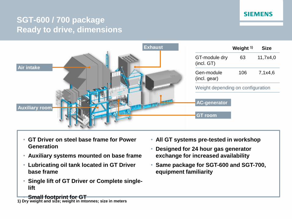
SGT-600 / 700 package
Ready to drive, dimensions
• GT Driver on steel base frame for Power
Generation
• Auxiliary systems mounted on base frame
• Lubricating oil tank located in GT Driver
base frame
• Single lift of GT Driver or Complete single-
lift
• Small footprint for GT
Air intake
AC-generator Auxiliary room
GT room
Exhaust
• All GT systems pre-tested in workshop
• Designed for 24 hour gas generator
exchange for increased availability
• Same package for SGT-600 and SGT-700,
equipment familiarity
Weight 1) Size
GT-module dry
(incl. GT)
63 11,7x4,0
Gen-module
(incl. gear)
106 7,1x4,6
Weight depending on configuration
1) Dry weight and size; weight in mtonnes; size in meters

Power Generation
Power output [MW(e)] 37.03
Fuel Natural Gas
Frequency [Hz] 50 / 60
(electrical) Efficiency 39.5 %
Heat rate [kJ/kWh / Btu/kWh] 9,120 / 8,644
Power Turbine speed [rpm] 6,100
Compressor pressure ratio 23.8:1
Exhaust gas flow [kg/s] / Temperature [ºC] 114.2 / 459
NOx Emissions (with DLE, corrected to
15% O2 dry) ≤15 ppmV
SGT-750 performance and application overview
Field of application
• Simple / combined cycle
applications
• Combined heat and power (CHP)
• Onshore power generator for oil
field service, refinery
applications
Strengths
• Long time between Major Overhaul (68,000
equivalent operating hours) – maximized uptime 17
days / 17 years
• In situ maintenance or gas generator removal to
workshop. 24 hour gas generator exchange.
• High efficiency
• Low Emissions – Single digit NOx capability
• Fast start time <10 min, suitable for peaker
application
• Rapid load changes Fleet (2 units ordered as of Dec. 2014)
• Industrial Power Generation
• 1 units ordered
• Oil & Gas
• 1 units ordered for PG
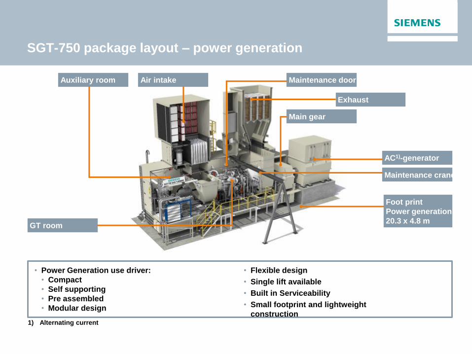
SGT-750 package layout – power generation
• Power Generation use driver:
• Compact
• Self supporting
• Pre assembled
• Modular design
Air intake Auxiliary room
GT room
AC1)-generator
Exhaust
Maintenance crane
Maintenance door
Main gear
Foot print
Power generation
20.3 x 4.8 m
• Flexible design
• Single lift available
• Built in Serviceability
• Small footprint and lightweight
construction 1) Alternating current

• High efficiency in combined cycle and cogeneration
applications
• Flexible and robust industrial design with high
reliability and long time between overhaul (60,000
EOH)
• A simple fuel flexible DLE system with excellent
emission levels
• In situ maintenance or spare core engine removal to
workshop. 48 hour core exchange with single lift
package
SGT-800 performance and application overview
Power Generation 47.5 MW Version 50.5 MW Version 53 MW Version
Power output [MW(e)] 47.5 50.5 53
Fuel Natural gas and other gases within specification / Diesel no2
Frequency [Hz] 50 / 60 50 / 60
(Electrical) Efficiency 37.7% 38.3%
Heat rate [kJ/kWh /
Btu/kWh] 9,557 / 9,058 9,407 / 8,916
Turbine speed [rpm] 6,608 6,608
Compressor pressure
ratio 20.4:1 21.1:1
Exhaust gas flow [kg/s] / Temperature [ºC]
132.8 / 541 134.2 / 553
NOx Emissions (with
DLE, corrected to 15% O2
dry)
≤15 ppmV ≤15 ppmV
Field of application
• Simple cycle baseload
• Combined heat and power (CHP)
• Combined cycle applications
• Power generation for the O&G
industry
Strengths
Fleet (250 units ordered as of Dec. 2014)
• Industrial Power Generation
• 212 units ordered (of which 158 in CC application)
• Oil & Gas
• 38 units ordered for PG application

Single lift package (about 60 days E&C) Classic package (about 80 days E&C)
Short base frame with gear box
directly on foundation with generator
Medium base frame with gear
box on base frame with core
engine
Option 1: Short skid package
Option 2: Medium skid package
Reduced erection and commissioning time on
customer site to about 60 working days
Reduced customer site manpower requirements
Reduced footprint with 4.5 m enclosure width
New maintenance options maximizing
availability
– 48 hour core engine exchange
Fulfils oil & gas industry requirements
SGT-800 package design

Industrial RB211 performance and application
overview
Field of application
• Off-shore power generation
• Industrial power generation /
cogeneration
Strengths
• Proven track record
• Qualified in oil &gas
• High simple cycle efficiency
• High power density
• High cycle capability
• High inert fuel capability
• No hot lock outs
• No EOH counters
Fleet (779 units as of Dec. 2014)
• 180 – Units Power generation
331 – Units Offshore
Over 35 millions service hours accumulated
Power Generation
Power output [MW(e)] 27.2 - 32.1
Fuel Gas & Liquid (dual fuel)
Frequency [HZ] Gearbox required for
electrical generation
(Electrical) Efficiency 34.8%–38.1%
Heat rate [(kJ / kWh)] 9,160–9,900
Turbine speed [rpm] 4800–4850 (100% rated
speed)
Compressor pressure ratio 20.6–22.1
Exhaust gas flow [kg / s] / Temperature [C] 91.3–96.1 kg/s / 500–510ºC
NOx Emissions (with DLE, corrected to 15%
O2 dry) ≤25 ppmV

Industrial RB211 package layout
Air intake
Exhaust system
Enclosure ventilation
GT enclosure
Power Turbine
Base plate with space
for GT Fuel and Lube Oil
systems
Driver for power generation with baseline variants for onshore and offshore.

Industrial Trent performance and application
overview
Strengths • High simple cycle efficiency • High cycle capability • High power density • Fast start and restart • High torque (no helpers) • Proven in power generation • Less stress on stream cycle components
Fleet (96 units as of Dec. 2014) • Power Generation
• >70 units operational • ~26 units on order or in commissioning
Variants • TRENT 60 DLE 50/60 Hz PG • TRENT 60 DLE 50/60 Hz ISI PG • TRENT 60 WLE DF 50/60 Hz PG • TRENT 60 WLE DF 50/60 Hz ISI PG
1) Source Gas Turbine World Handbook 2013
DLE : dry-low emissions, WLE: water-injected low emissions, DF: Dual Fuel, ISI: Inlet Spray Intercooling,
Power MW 54.0 - 65.6
SC Efficiency (AC), iso, % 41–43.4
CC Efficiency (AC), iso, % 50–54.5
Exhaust temperature, Deg C 409–444
Exhaust mass flow, kg / s 151–179
PRICE, USD / kW 1) 300-336
Compressor pressure ratio 35:1
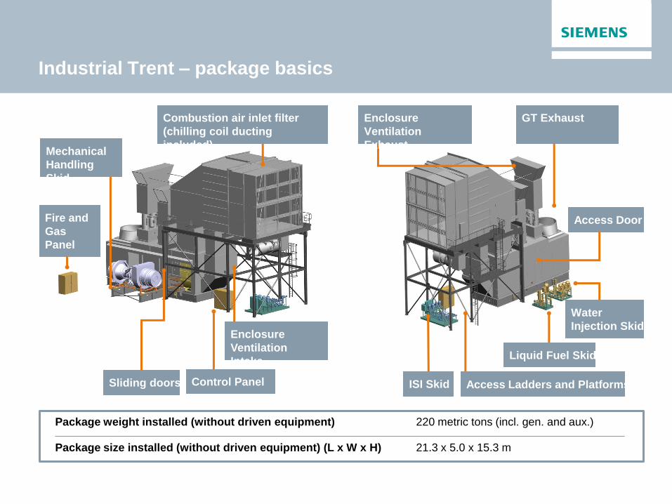
Industrial Trent – package basics
Sliding doors
Mechanical
Handling
Skid
Enclosure
Ventilation
Intake
Control Panel
Fire and
Gas
Panel
Access Door
ISI Skid
Combustion air inlet filter
(chilling coil ducting
included)
GT Exhaust Enclosure
Ventilation
Exhaust
Water
Injection Skid
Liquid Fuel Skid
Access Ladders and Platforms
Package weight installed (without driven equipment) 220 metric tons (incl. gen. and aux.)
Package size installed (without driven equipment) (L x W x H) 21.3 x 5.0 x 15.3 m

Power & Gas Division
Key project: gas turbine cogeneration
Alco Bio Fuels
Harbor of Ghent
production of bio-ethanol
Cogeneration by installing gas turbine:
combined production of heat and electricity
saving of primary energy compared to
standard separate production
Gas Turbine
Siemens SGT-400
12,9 MW rating and not 15 MW rating because
of grid connection limitation
DLE Combustion System lower emissions
High electrical efficiency of gas turbine 34,5%
combined with high steam production
efficiency (28,3 T/h without post combustion)
Questions?
Modernization & optimization of power
generation units Gautier Cogels
Caroline Davidovic
Wouter Van Parys
Siemens Turbine Day – June 3rd

Siemens Offers a Wide Range of I&C Systems,
Products and Services for Power Plants
Automation and Control System
Turbine Controller and Generator Electricals
Solutions for Plant Optimization
Electrical Equipment
Innovations for the future
Siemens Offers a Wide Range of I&C Systems,
Products and Services for Power Plants
Automation and Control System
Turbine Controller and Generator Electricals
Solutions for Plant Optimization
Electrical Equipment
Innovations for the future
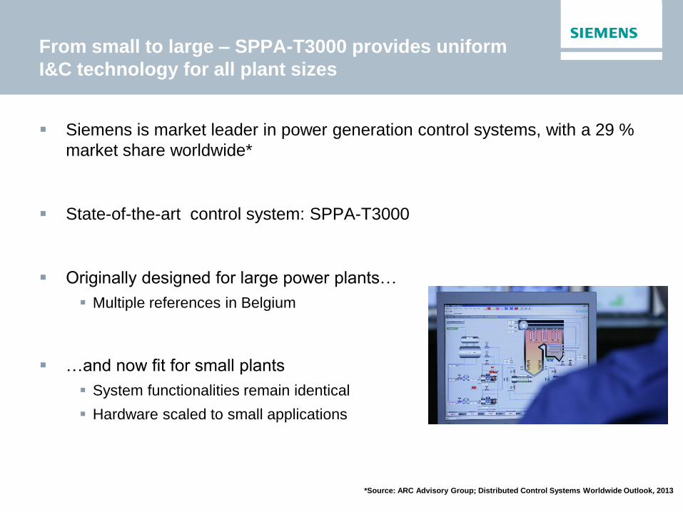
From small to large – SPPA-T3000 provides uniform
I&C technology for all plant sizes
Siemens is market leader in power generation control systems, with a 29 %
market share worldwide*
State-of-the-art control system: SPPA-T3000
Originally designed for large power plants…
Multiple references in Belgium
…and now fit for small plants
System functionalities remain identical
Hardware scaled to small applications
*Source: ARC Advisory Group; Distributed Control Systems Worldwide Outlook, 2013

What do you expect from a DCS system?
A reliable system... ...to increase availability of your power plants
... to reduce overall
cost for DCS and
to protect the
investment
A comprehensive
solution provider
“beyond DCS”...
... to improve
efficiency as well
as profitability
… and why What you want ...
A DCS optimized
for efficient trouble
shooting, fault
analysis and user
guidance ...
A DCS for a plant
life cycle …
... for shortest outage times and minimized risks

SPPA-T3000 – Intrinsically integrated data ensures
data consistency at all times
All data available from one source
All data intrinsically embedded
in every object
Different views possible for different
user roles
All the information is available,
at a glance
Reliable for in-build data consistency

SPPA-T3000 – Uniform system for all tasks -
operation, engineering and diagnostics
Operation
Alarm
Diagnostics
Field
Archive Engineering
A single user interface for optimum and safe handling
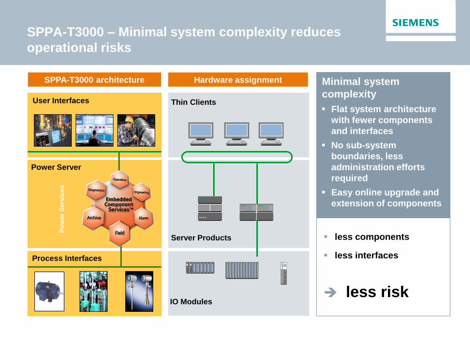
SPPA-T3000 – Minimal system complexity reduces
operational risks
Flat system architecture
with fewer components
and interfaces
No sub-system
boundaries, less
administration efforts
required
Easy online upgrade and
extension of components
Hardware assignment SPPA-T3000 architecture
Thin Clients
Server Products
IO Modules
Minimal system
complexity
less components
less interfaces
less risk
User Interfaces
Po
wer
Serv
ices
Power Server
Process Interfaces
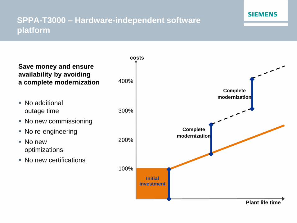
SPPA-T3000 – Hardware-independent software
platform
Save money and ensure
availability by avoiding
a complete modernization
No additional
outage time
No new commissioning
No re-engineering
No new
optimizations
No new certifications
costs
Plant life time
Complete
modernization
Initial investment
Complete
modernization
100%
200%
300%
400%

Best-in-class SIMATIC S7 Automation Servers
High Available Application Server Components
High Quality SIMATIC Network
Proven IO (incl HART capability)
SPPA-T3000 – Reliable by using best-in-class
components
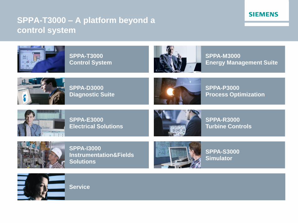
SPPA-T3000 – A platform beyond a
control system
SPPA-D3000 Diagnostic Suite
SPPA-E3000 Electrical Solutions
SPPA-S3000 Simulator
SPPA-I3000 Instrumentation&Fields Solutions
SPPA-T3000 Control System
SPPA-M3000 Energy Management Suite
SPPA-P3000 Process Optimization
SPPA-R3000 Turbine Controls
Service
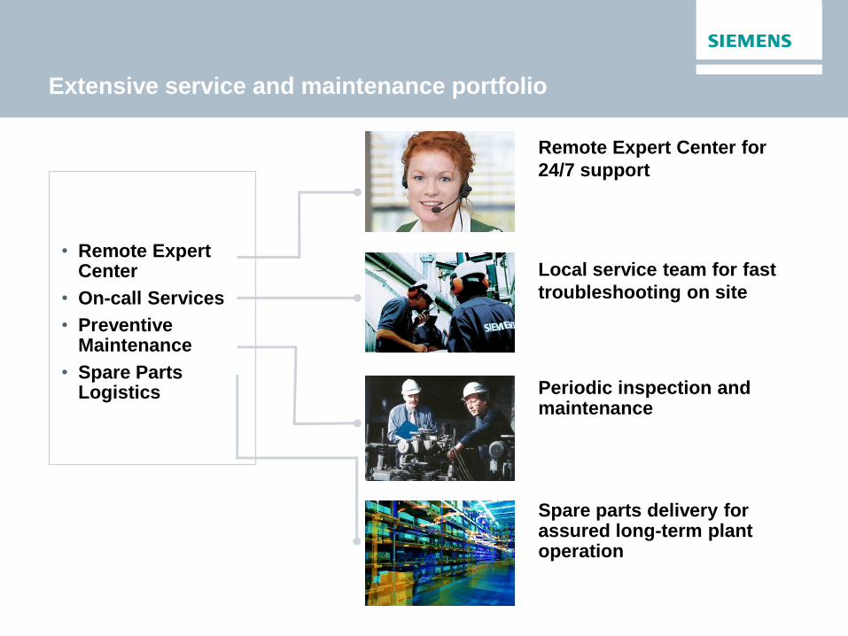
Extensive service and maintenance portfolio
Remote Expert Center for
24/7 support
Local service team for fast
troubleshooting on site
• Remote Expert Center
• On-call Services
• Preventive Maintenance
• Spare Parts Logistics
Spare parts delivery for assured long-term plant operation
Periodic inspection and maintenance
Siemens Offers a Wide Range of I&C Systems,
Products and Services for Power Plants
Automation and Control System
Turbine Controller and Generator Electricals
Solutions for Plant Optimization
Electrical Equipment
Innovations for the future
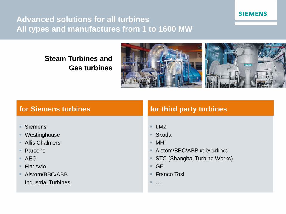
Advanced solutions for all turbines
All types and manufactures from 1 to 1600 MW
for Siemens turbines for third party turbines
Siemens
Westinghouse
Allis Chalmers
Parsons
AEG
Fiat Avio
Alstom/BBC/ABB
Industrial Turbines
LMZ
Skoda
MHI
Alstom/BBC/ABB utility turbines
STC (Shanghai Turbine Works)
GE
Franco Tosi
…
Steam Turbines and
Gas turbines

Compact innovative solution for industrial steam
turbines
Steam Turbine Governor System Integrated Generator Electrical Solution
Cost optimized small footprint product based on technology and concepts proven in large scale applications

Siemens concepts for industrial applications –
turbine governor and protection
Standard package:
Turbine controller
AS3000 & AddFEM PoCo
HMI
Simatic Touch Panel PC
Optional package:
Control of auxiliaries
realized in AS3000 & ET200M
Vibration monitoring
with VIB3000 or a very cheap
transmitter solution
Overspeed & protection
with Braun E16
Integrated SPPA-T3000
Engineering
Overspeed &
Protection Braun E16
Vibration
Monitoring VIB3000
HMI Touch Panel
Governor AddFEM
PoCo
Controller AS3000
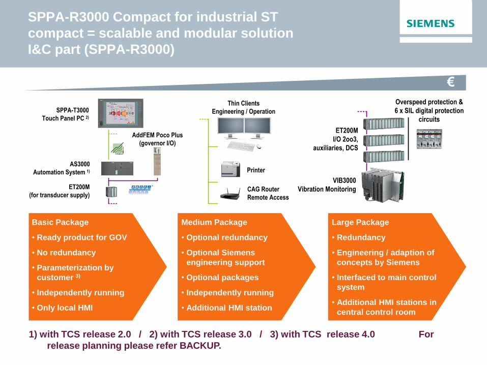
SPPA-R3000 Compact for industrial ST
compact = scalable and modular solution
I&C part (SPPA-R3000)
€
Basic Package
• Ready product for GOV
• No redundancy
• Parameterization by
customer 3)
• Independently running
• Only local HMI
Medium Package
• Optional redundancy
• Optional Siemens
engineering support
• Optional packages
• Independently running
• Additional HMI station
Large Package
• Redundancy
• Engineering / adaption of
concepts by Siemens
• Interfaced to main control
system
• Additional HMI stations in
central control room
1) with TCS release 2.0 / 2) with TCS release 3.0 / 3) with TCS release 4.0 For
release planning please refer BACKUP.
Overspeed protection &
6 x SIL digital protection
circuits
VIB3000
Vibration Monitoring
ET200M
I/O 2oo3,
auxiliaries, DCS
Thin Clients
Engineering / Operation
Printer
CAG Router
Remote Access
SPPA-T3000
Touch Panel PC 2)
AS3000
Automation System 1)
ET200M
(for transducer supply)
AddFEM Poco Plus
(governor I/O)

Turbine modernization concept – electronic governor
and protection
E
Control valves
H
Stop- valves
Tripping Unit
Speed Sensors
Turbine Governor
Overspeed protection
Lube oil tank
Protection Channel 1
Protection Channel 2
Protection Channel 3
2v3
• Electronic turbine governor
• 2oo3 electronic protection with 2oo3 tripping unit
• Independent 3-channel electronic over speed trip according to SIL3
• Simplified hydraulic only used for valve actuating
- no hydraulic/mechanical governors
- no hydraulic/mechanical protection
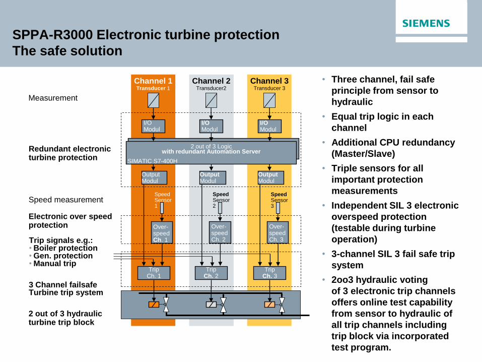
SPPA-R3000 Electronic turbine protection
The safe solution
Trip Ch. 2
Trip Ch. 3
Trip Ch. 1
Measurement
Speed Sensor 1
Speed Sensor 2
Speed Sensor 3
Output Modul
Output Modul
Output Modul
I/O Modul
I/O Modul
I/O Modul
Channel 3 Transducer 3
Channel 2 Transducer2
Channel 1 Transducer 1
2 out of 3 Logic with redundant Automation Server
SIMATIC S7-400H
Over-speed Ch. 1
Over-speedCh. 2
Over-speed Ch. 3
• Three channel, fail safe
principle from sensor to
hydraulic
• Equal trip logic in each
channel
• Additional CPU redundancy
(Master/Slave)
• Triple sensors for all
important protection
measurements
• Independent SIL 3 electronic
overspeed protection
(testable during turbine
operation)
• 3-channel SIL 3 fail safe trip
system
• 2oo3 hydraulic voting
of 3 electronic trip channels
offers online test capability
from sensor to hydraulic of
all trip channels including
trip block via incorporated
test program.
Redundant electronic turbine protection
Speed measurement
Electronic over speed protection
Trip signals e.g.: • Boiler protection • Gen. protection • Manual trip
3 Channel failsafe Turbine trip system
2 out of 3 hydraulic turbine trip block
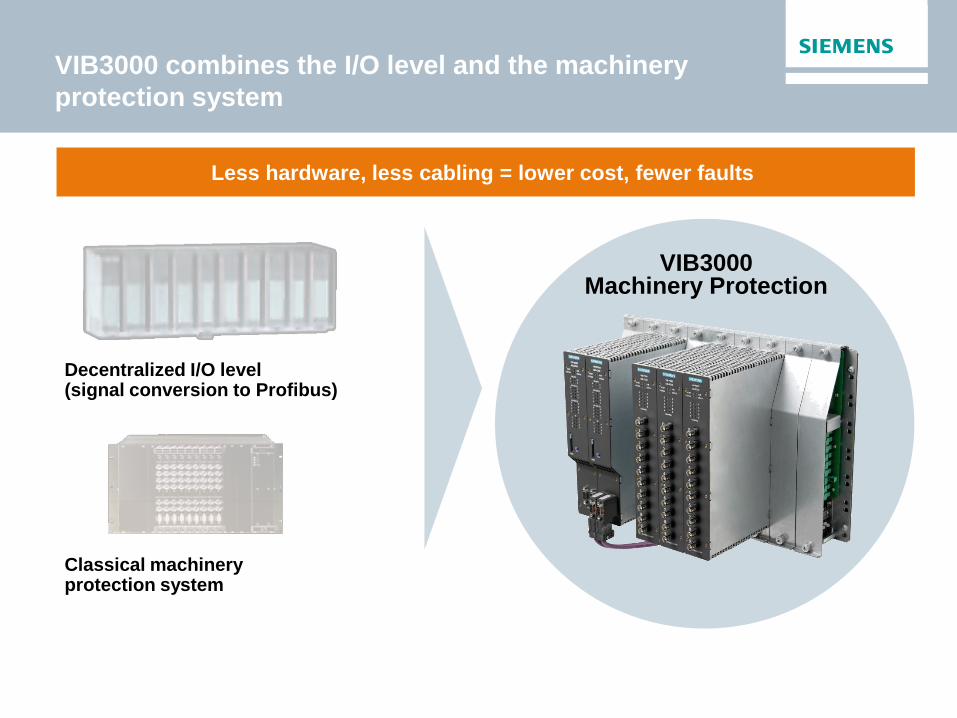
VIB3000 combines the I/O level and the machinery
protection system
Less hardware, less cabling = lower cost, fewer faults
VIB3000 Machinery Protection
Classical machinery protection system
Decentralized I/O level (signal conversion to Profibus)
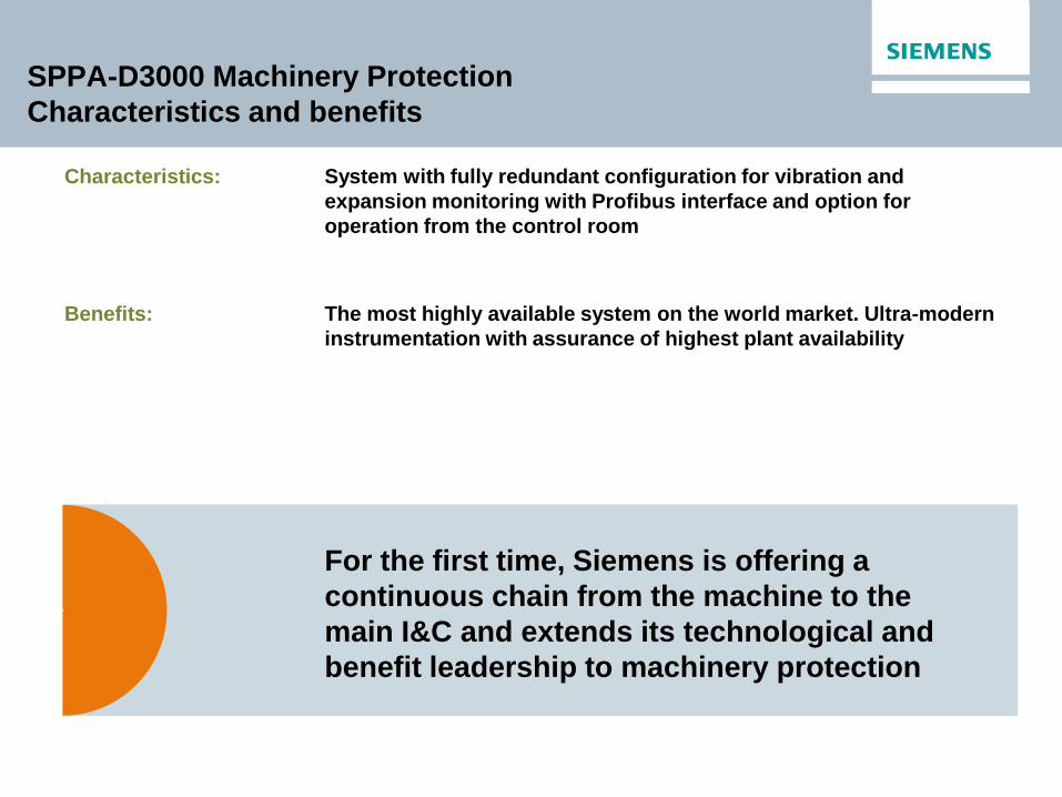
SPPA-D3000 Machinery Protection
Characteristics and benefits
System with fully redundant configuration for vibration and
expansion monitoring with Profibus interface and option for
operation from the control room
For the first time, Siemens is offering a
continuous chain from the machine to the
main I&C and extends its technological and
benefit leadership to machinery protection
Characteristics:
Benefits: The most highly available system on the world market. Ultra-modern
instrumentation with assurance of highest plant availability

What does a protection system do?
Sense – Process – Transmit
Machinery monitoring
SPPA-T3000 visualization
Module redundancy
Profibus redundancy
Reliable transmission of results
• Redundant Profibus
• Safety relay
• Analog signals
Reliable processing of signal data
• Derivation of overall readings
• Limit comparison
• Logic gating
• Self-monitoring
Reliable sensing of signal data
• Vibration
• Pressure fluctuations
• Expansion and positions
• Speed/direction of rotation
• Differential pressure
• etc.

Siemens concepts for industrial applications –
generator electricals
Standard package:
Excitation System
including Automatic Voltage
Regulation (AVR)
Generator Protection
SIPROTEC 7UM
Synchronisation
SIPROTEC 7VE
Optional package:
Unit and grid protection
Electrical metering
MV & LV switchgears
UPS
Startup Frequency
Converter (SFC)
Excitation AVR
Synchronisation SIPROTEC 7VE
Protection SIPROTEC 7UM

SPPA-R3000 Compact TGS –
the solution product for all industrial turbines
SPPA-R3000 Compact TGS is our governor solution for following industrial applications:
Category – number of stages:
• One-stage industrial steam turbine (HP)
• Two-stage industrial steam turbine (HP, LP)
• Three-stage industrial steam turbine (HP, IP,
LP)
Category – exhaust pressure:
• Condensation industrial steam turbines
• Back pressure industrial steam turbines
Category – drive:
• Industrial steam turbines used for generators
• Industrial steam turbines used for driving
engines
Category – extraction lines:
• Industrial steam turbines with one extraction
line
• Industrial steam turbines with two extraction
lines
Turbine categories Process Functions*
Closed loop functions:
• speed controller / frequency control
• load controller
• up to 5 auxiliary controller (auxiliary = load, initial
pressure, back pressure and wheel chamber
pressure)
• steam extraction map
• integrated valve position controller for up to 4
valves
• valve split range control for second HP control
valve
Start-up functions:
• manual / automatic start-up with start-up permissive
logic
• automatic start-up with maximum five fixed curves
• acceleration limiter / casing temp protection
• avoidance of critical speed ranges
• auto / manual synchronization with external /
internal
commands
* for detailed description please refer
product portfolio brochure

SPPA-R3000 Compact TCS –
scalable and future proof
ready product – easy adoption to plant by specific parameters
no changes or adoption of control algorithm needed
proven Siemens HW technology: standardised, scalable and extendable
easy integration into an overall Siemens SPPA-T3000 plant I&C concept
common operation and monitoring with the plant DCS
same design and engineering tools with the plant DCS
same spare parts and world-wide Siemens service
Safe and economic operation of your plant

Siemens Offers a Wide Range of I&C Systems,
Products and Services for Power Plants
Automation and Control System
Turbine Controller and Generator Electricals
Solutions for Plant Optimization
Electrical Equipment
Innovations for the future
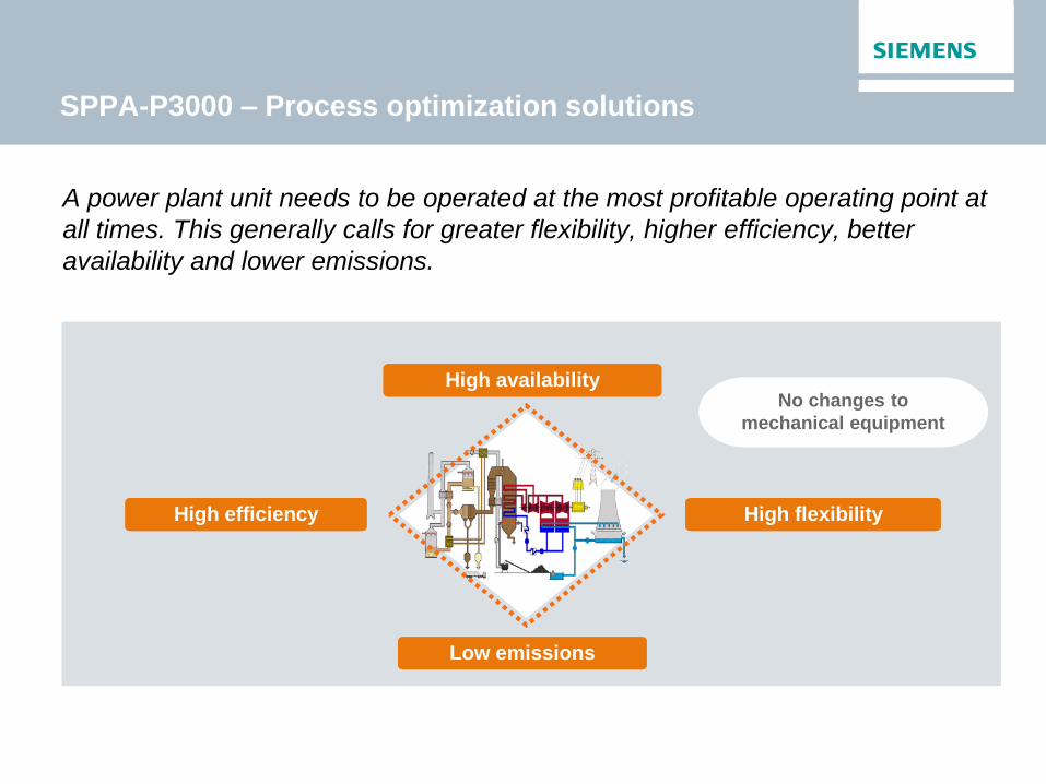
High availability
Low emissions
A power plant unit needs to be operated at the most profitable operating point at
all times. This generally calls for greater flexibility, higher efficiency, better
availability and lower emissions.
High flexibility High efficiency
No changes to
mechanical equipment
SPPA-P3000 – Process optimization solutions

SPPA-P3000 – Modern control concepts form the
basis for high profitability
Optimum operating behavior
Modern control principles State space control
Predic- tive control
Intrinsic stability
High profitability High
flexibility
High
efficiency
High
availability
Low
emissions
High control quality
High stability
Model-based feed forward
control
High repeatability
Decoup- ling
Neural networks
Based on modern control concepts:
• Model-based, predictive feed forward
structures
• Exploitation of inherently stable
processes
• Decoupling of highly intermeshed
subprocesses
• State space control
• Neural networks and fuzzy logic
The resulting operating behavior is extremely stable, while providing a flexible and fast response
Fuzzy logic
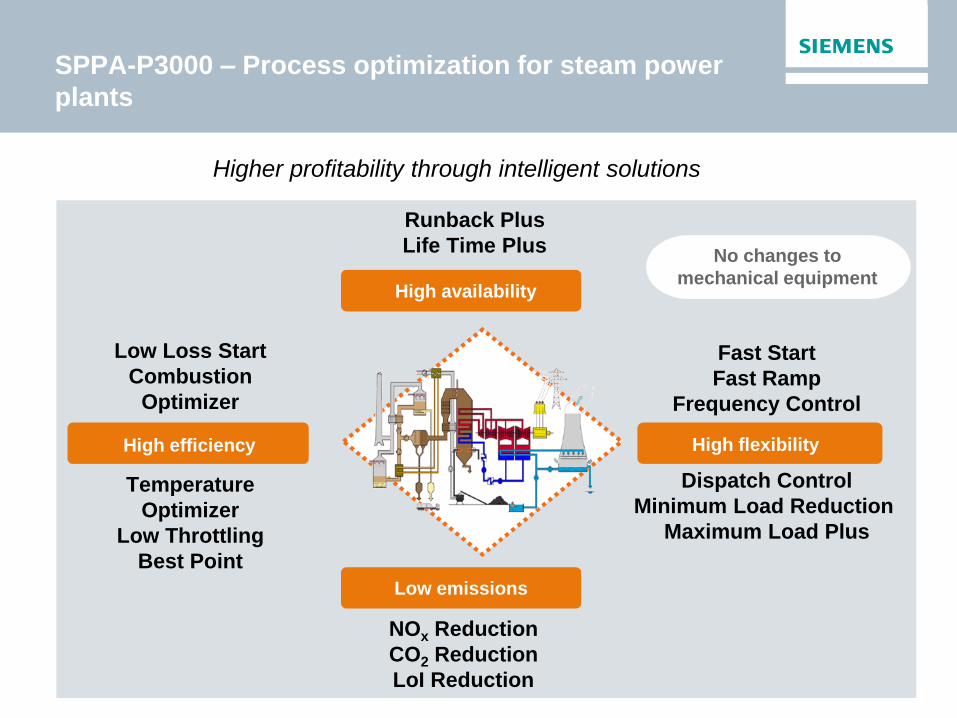
SPPA-P3000 – Process optimization for steam power
plants
High efficiency
High availability
High flexibility
Low emissions
Runback Plus
Life Time Plus
No changes to
mechanical equipment
Fast Start
Fast Ramp
Frequency Control
Dispatch Control
Minimum Load Reduction
Maximum Load Plus
NOx Reduction
CO2 Reduction
LoI Reduction
Low Loss Start
Combustion
Optimizer
Temperature
Optimizer
Low Throttling
Best Point
Higher profitability through intelligent solutions

Optimization operating regime in case of multiple
turbines
Scenario analysis of different operating regimes based on
thermodynamic calculations
Sensitivity analysis for different parameters
Optimized load dispatch schedule
Determination of optimum operational conditions

Special Case : Hybrid controller for waste incineration plants
Increase steam mass flow and waste
throughput
• Controlling setpoints of process
parameters (e.g. primary & secudary
air)
• by real-time measurement of process
indicators (e.g. steam flow,
temperature)
• and optimization using a hybrid
controller (model-based + fuzzy logic)
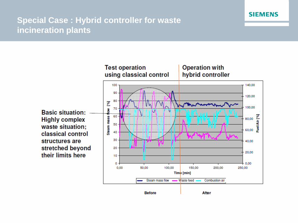
Special Case : Hybrid controller for waste
incineration plants

Special Case : Hybrid controller for waste
incineration plants

Siemens Offers a Wide Range of I&C Systems,
Products and Services for Power Plants
Automation and Control System
Turbine Controller and Generator Electricals
Solutions for Plant Optimization
Electrical Equipment
Innovations for the future
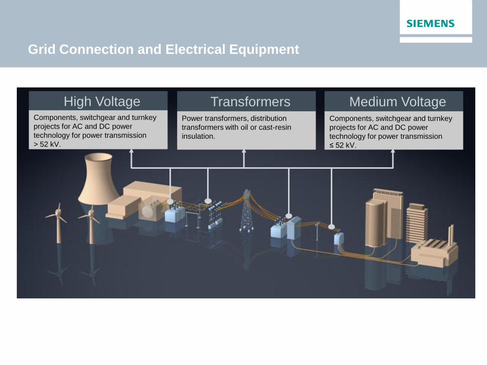
Grid Connection and Electrical Equipment
High Voltage Transformers Medium Voltage Components, switchgear and turnkey
projects for AC and DC power
technology for power transmission
≤ 52 kV.
Components, switchgear and turnkey
projects for AC and DC power
technology for power transmission
> 52 kV.
Power transformers, distribution
transformers with oil or cast-resin
insulation.

Siemens Offers a Wide Range of I&C Systems,
Products and Services for Power Plants
Automation and Control System
Turbine Controller and Generator Electricals
Solutions for Plant Optimization
Electrical Equipment
Innovations for the future
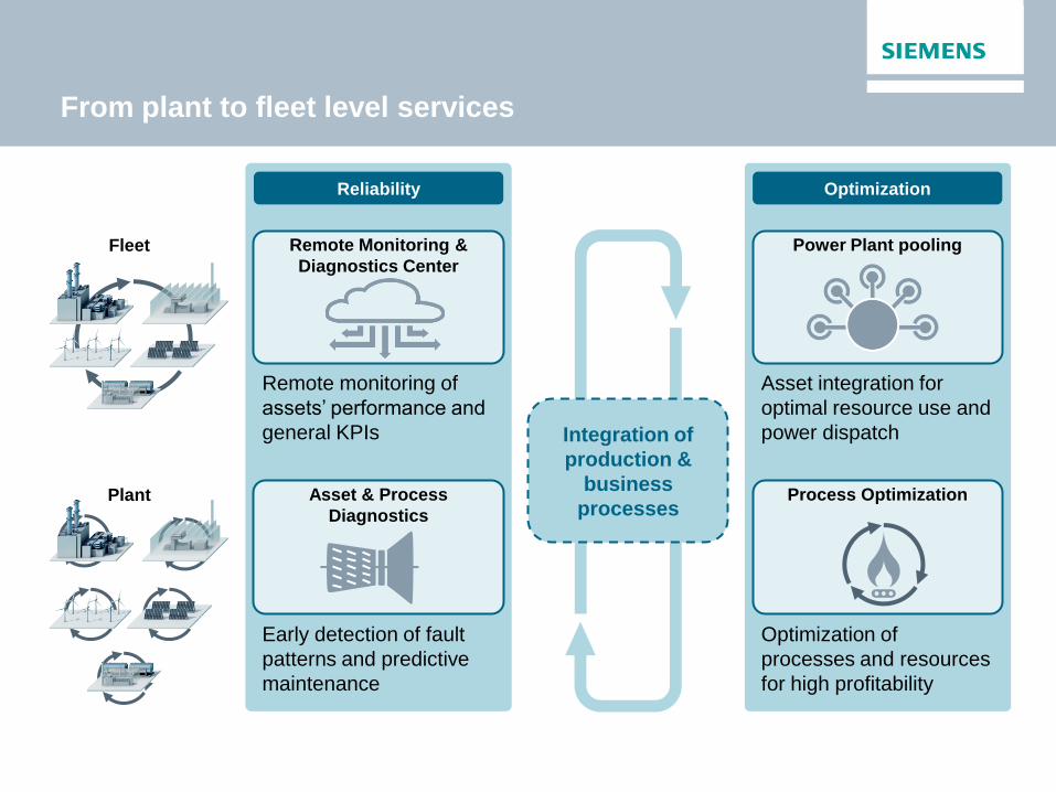
From plant to fleet level services
Plant
Fleet
Process Optimization
Remote Monitoring &
Diagnostics Center
Asset integration for
optimal resource use and
power dispatch
Early detection of fault
patterns and predictive
maintenance
Remote monitoring of
assets’ performance and
general KPIs
Optimization of
processes and resources
for high profitability
Reliability Optimization
Power Plant pooling
Asset & Process
Diagnostics
Integration of
production &
business
processes

Combining Siemens portfolio into future
district heating network

Questions?

It’s time for lunch!
Maintenance Patrick De Jode
Didier Ollevier
Siemens Turbine Day – June 3rd 2015
Presentation of the service team.
Remote Diagnostic System.
Maintenance concept.
Introduction / Content
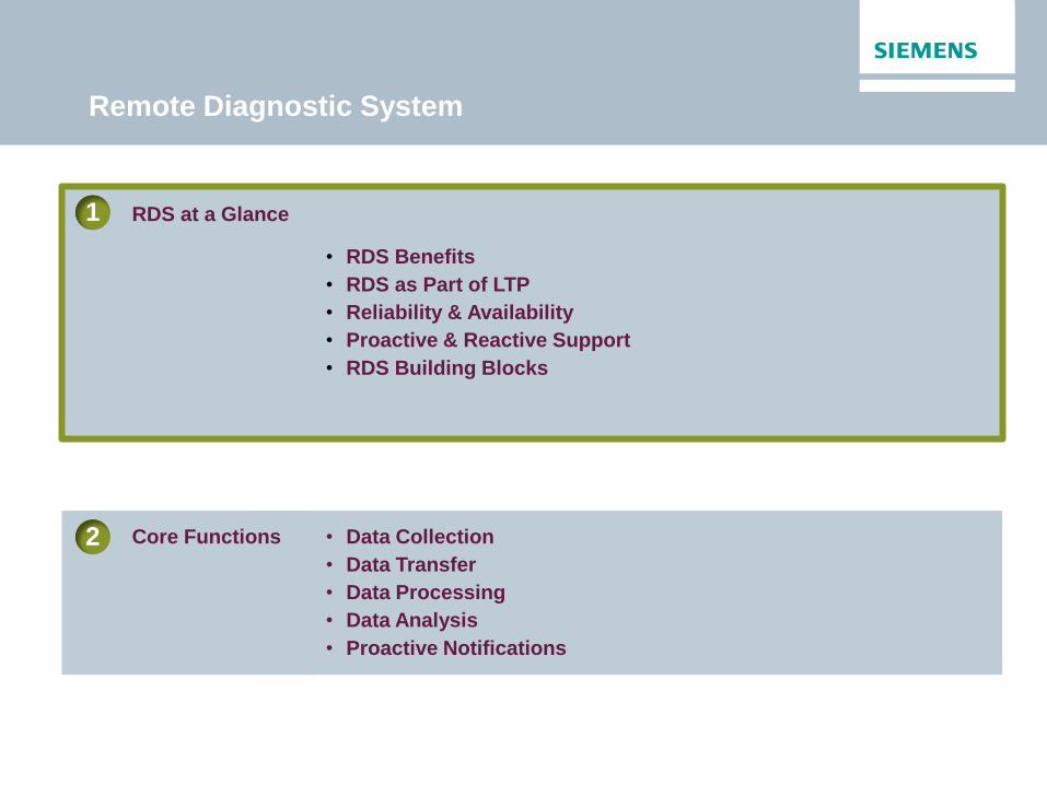
• RDS Benefits
• RDS as Part of LTP
• Reliability & Availability
• Proactive & Reactive Support
• RDS Building Blocks
RDS at a Glance
1
• Data Collection
• Data Transfer
• Data Processing
• Data Analysis
• Proactive Notifications
Core Functions
2
Remote Diagnostic System

Benefits of Remote Diagnostic Service
• Increase of reliability & availability through
proactive support
• Continuous information flow between
Customers’ operational and OEM engineering
know-how
• Benchmark on fleet KPIs with industry peer
group
• Participation in Siemens continuous R&D
activities in the area of failure pattern
recognition & advanced diagnostic algorithm
and tools
• Improved responsiveness in case of an event
through advanced remote troubleshooting
Identify a potential failure before it impacts operation

RDS is an integral part of Siemens high value Long Term Programs
• Maintenance
programs can
help with your
long-term
operational
planning
• Various levels of
LTP contracts can
be tailored to the
requirements of
your specific
equipment
Long Term
Programs Options
Corrective Contract
Preventive Contract
Remote Diagnostic Services (RDS) Proactive technical expert advice to minimise risk of forced outage events
Support Contract
Framework / Call off Agreements
Siemens Long Term
Programs (LTP)
RDS as part of Siemens Long Term Programs (LTP)
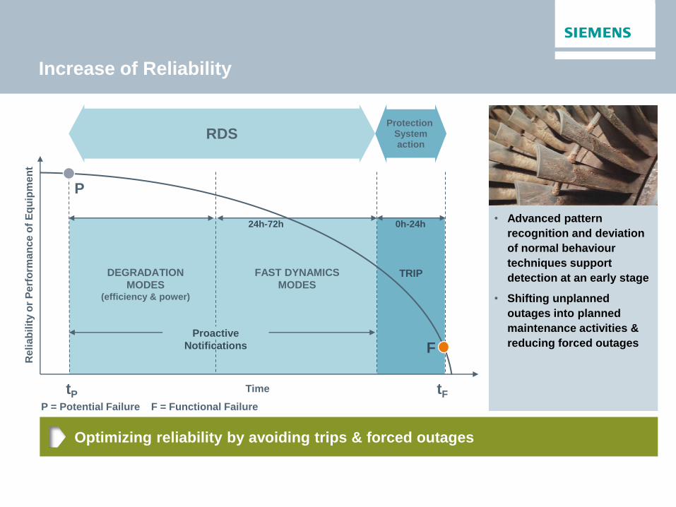
Protection System action
tP
RDS
tF
TRIP
P
0h-24h
P = Potential Failure F = Functional Failure
F
Re
lia
bil
ity o
r P
erf
orm
an
ce
of
Eq
uip
me
nt
Time
Optimizing reliability by avoiding trips & forced outages
Increase of Reliability
• Advanced pattern
recognition and deviation
of normal behaviour
techniques support
detection at an early stage
• Shifting unplanned
outages into planned
maintenance activities &
reducing forced outages
24h-72h
DEGRADATION
MODES (efficiency & power)
Proactive
Notifications
FAST DYNAMICS
MODES

Optimising availability by optimising planned outages,
within the LTP contract frame
Increase of Availability
• Possibility of reducing
maintenance activities
• Shortening of major
outages by defining
corrective actions in
advance, providing pre-
outage reports and the
right tools
• Higher flexibility on time
between scheduled
outages due to historic
data analysis & daily
monitoring
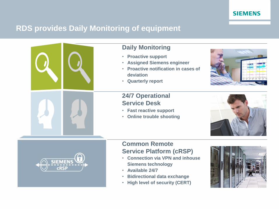
RDS provides Daily Monitoring of equipment
Daily Monitoring
• Proactive support
• Assigned Siemens engineer
• Proactive notification in cases of
deviation
• Quarterly report
24/7 Operational
Service Desk • Fast reactive support
• Online trouble shooting
Common Remote
Service Platform (cRSP) • Connection via VPN and inhouse
Siemens technology
• Available 24/7
• Bidirectional data exchange
• High level of security (CERT)
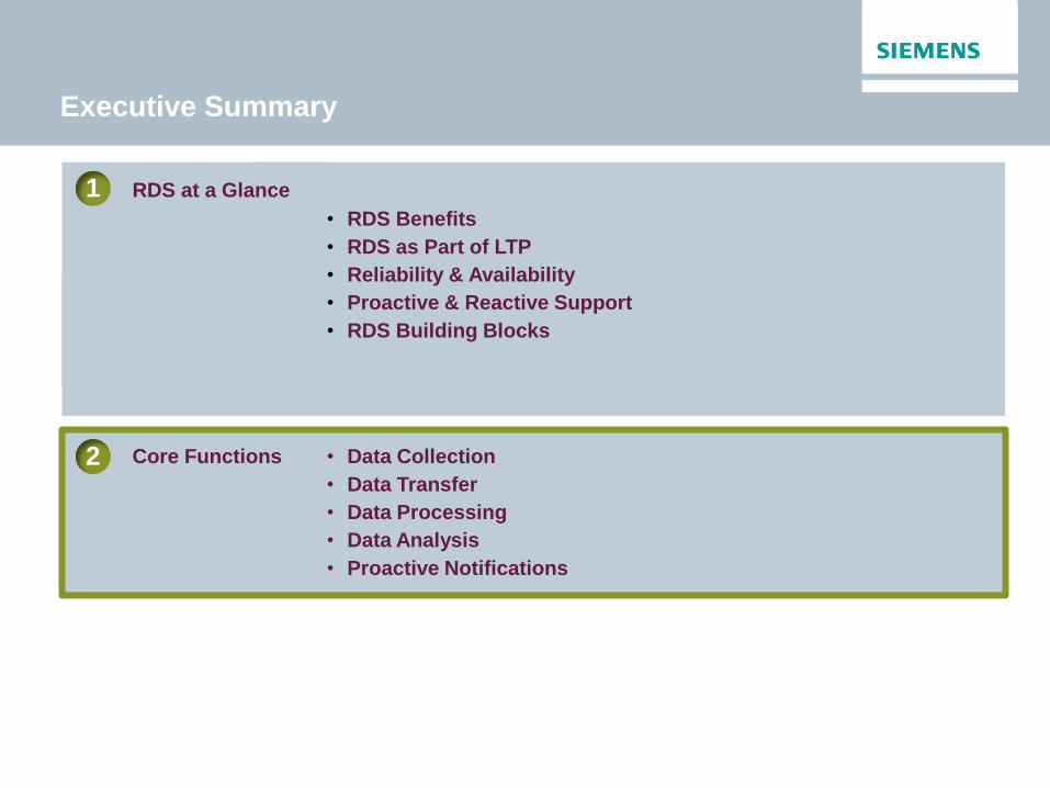
• RDS Benefits
• RDS as Part of LTP
• Reliability & Availability
• Proactive & Reactive Support
• RDS Building Blocks
RDS at a Glance
1
• Data Collection
• Data Transfer
• Data Processing
• Data Analysis
• Proactive Notifications
Core Functions
2
Executive Summary

Siemens Customer
Customer
Intranet
Customer
Firewall
Siemens
Firewall
cRSP
Servers
2. Data Transfer (cRSP)
3. Central Data Storage / Admin
Siemens
STA-RMS
Servers
5. Final Data Analysis Siemens Expert
4. Automated Data Processing Agents, Dashboard
6. Proactive Notifications
Quarterly Reports
7. Real Time Troubleshooting
HMI
Interaction
Streaming
Data
RDS Core Functions
1. Data Collection at Site
Customer Access Gateway
Siemens Customer
Customer
Intranet
Customer
Firewall
Siemens
Firewall
cRSP
Servers
2. Data Transfer (cRSP)
3. Central Data Storage / Admin
Siemens
STA-RMS
Servers
5. Final Data Analysis Siemens Expert
4. Automated Data Processing Agents, Dashboard
6. Proactive Notifications
Quarterly Reports
7. Real Time Troubleshooting
HMI
Interaction
Streaming
Data
1. Data Collection at Site
Customer Access Gateway
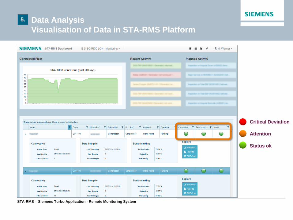
Critical Deviation
Attention
Status ok
STA-RMS = Siemens Turbo Application - Remote Monitoring System
5. Data Analysis
Visualisation of Data in STA-RMS Platform

Siemens Customer
Customer
Intranet
Customer
Firewall
Siemens
Firewall
cRSP
Servers
2. Data Transfer (cRSP)
3. Central Data Storage / Admin
Siemens
STA-RMS
Servers
5. Final Data Analysis Siemens Expert
4. Automated Data Processing Agents, Dashboard
6. Proactive Notifications
Quarterly Reports
7. Real Time Troubleshooting
HMI
Interaction
Streaming
Data
1. Data Collection at Site
Customer Access Gateway
STA-RMS = Siemens Turbo Application - Remote Monitoring System
5. Data Analysis
RDS Cockpit for Daily Monitoring (example)
Red: Units in a critical state (tripped , agent alerts etc.), not yet looked at by the RDS
Orange: The machine status has been acknowledged by an RDC engineer, interactions are ongoing
(Factfinding, Notification...)

Industrial Steam Turbine Maintenance
Contents
• Basics
• Objectives
• Causes
• Strategies
• Intervals
• Categories
• Interventions
• TMS
• Revamping
• Footprints

Industrial Steam Turbine Maintenance
Basic points to consider
• Familiarize yourself with your equipment and its testing posibilities
• Apply the preventive maintenance schedule
• Record and quantify all maintenance actions in a log
• Obtain recommended spare parts
• Keep your equipment clean and tidy
• Make sure inspection points are safe and practical to reach

Industrial Steam Turbine Maintenance
Maintenance objectives
• Prevent breakdown of the
equipment and guarantee
availability
• Maintain optimum
efficiency
• Provide the lowest possible
maintenance cost
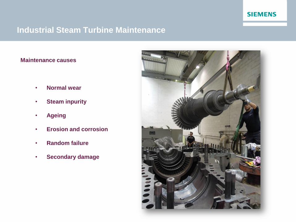
Industrial Steam Turbine Maintenance
Maintenance causes
• Normal wear
• Steam inpurity
• Ageing
• Erosion and corrosion
• Random failure
• Secondary damage

Industrial Steam Turbine Maintenance
Normal wear

Industrial Steam Turbine Maintenance
Steam impurity

Industrial Steam Turbine Maintenance
Ageing

Industrial Steam Turbine Maintenance
Erosion

Industrial Steam Turbine Maintenance
Random failure
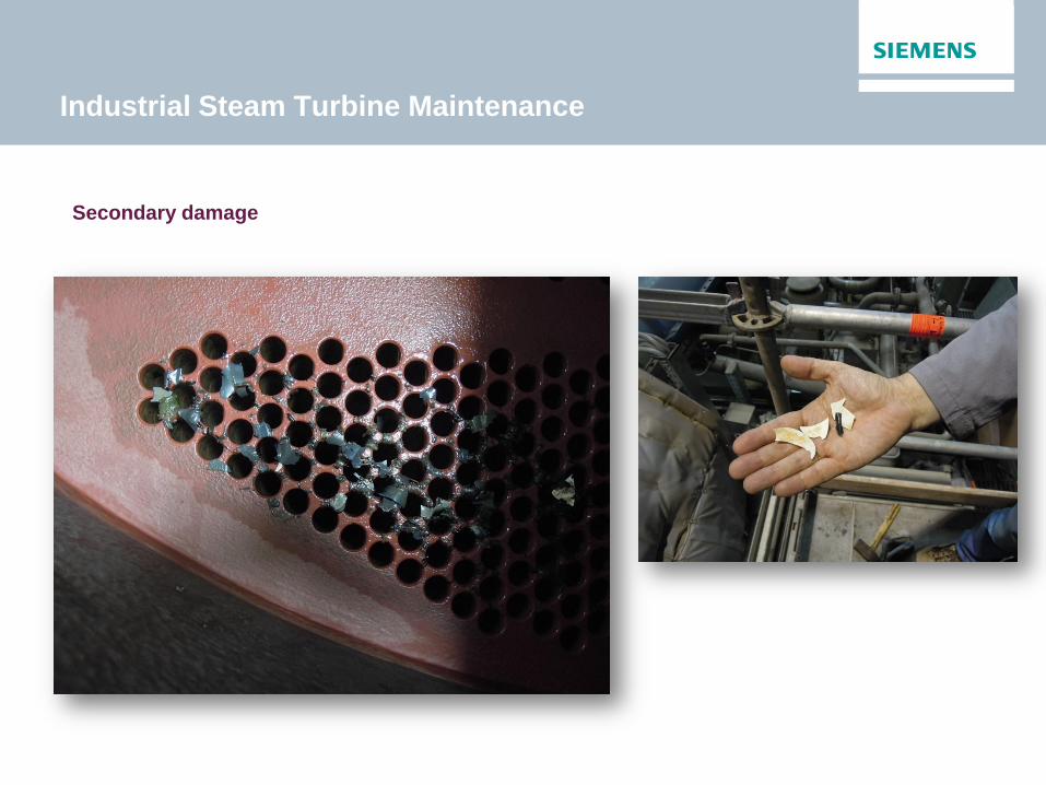
Industrial Steam Turbine Maintenance
Secondary damage
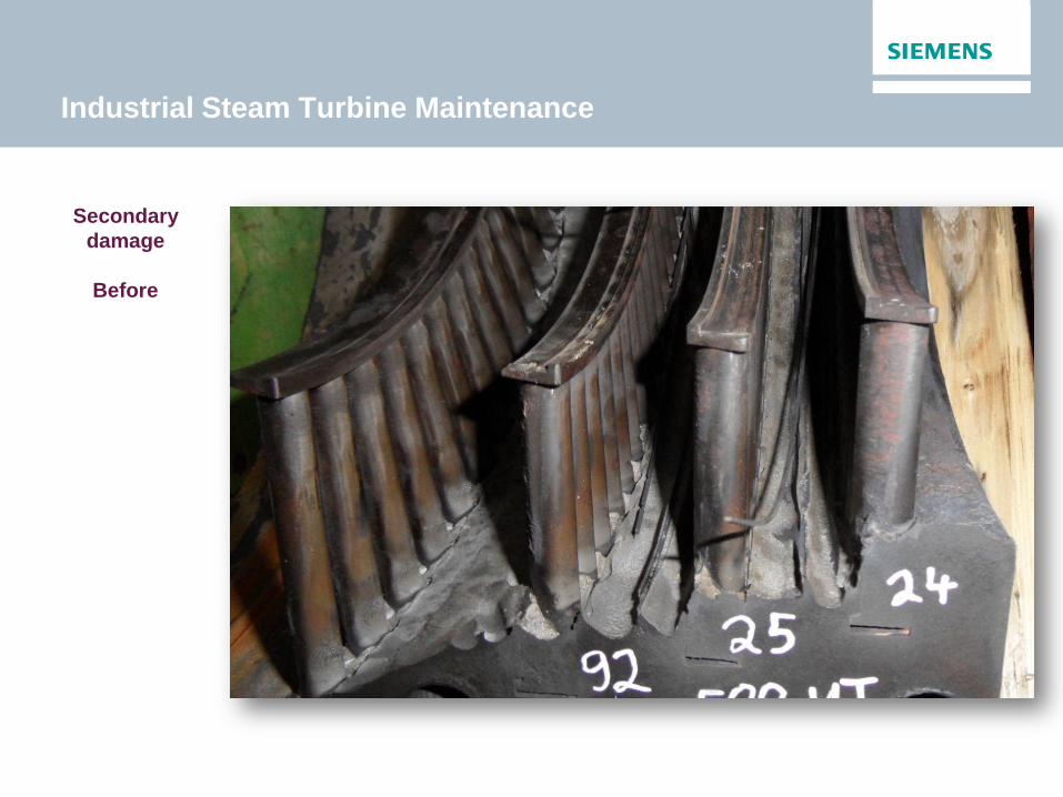
Industrial Steam Turbine Maintenance
Secondary
damage
Before
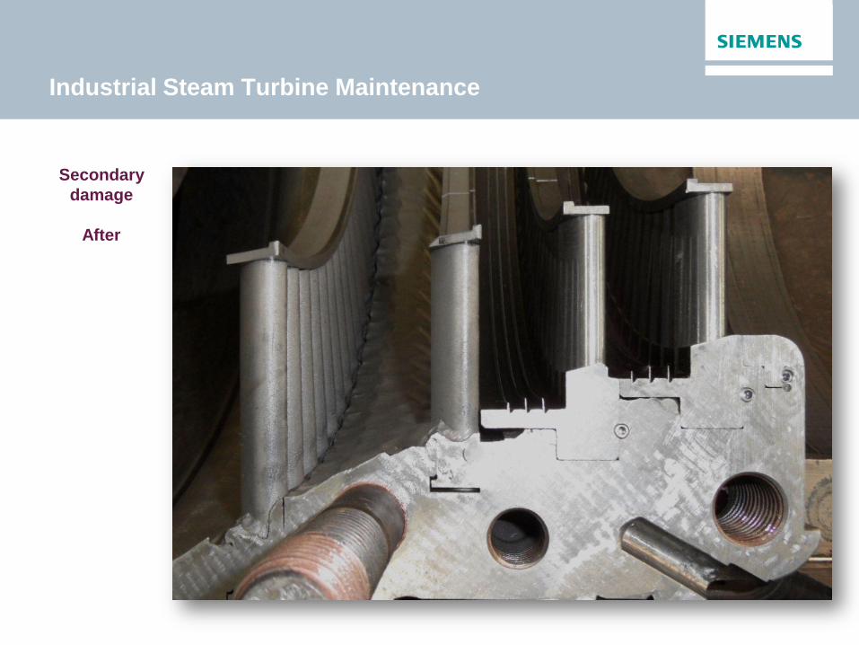
Industrial Steam Turbine Maintenance
Secondary
damage
After
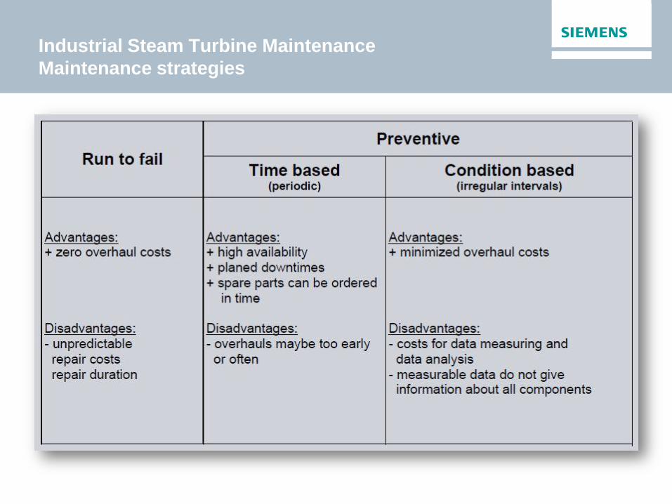
Industrial Steam Turbine Maintenance
Maintenance strategies
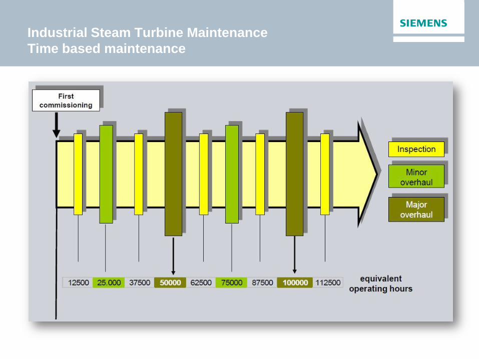
Industrial Steam Turbine Maintenance
Time based maintenance
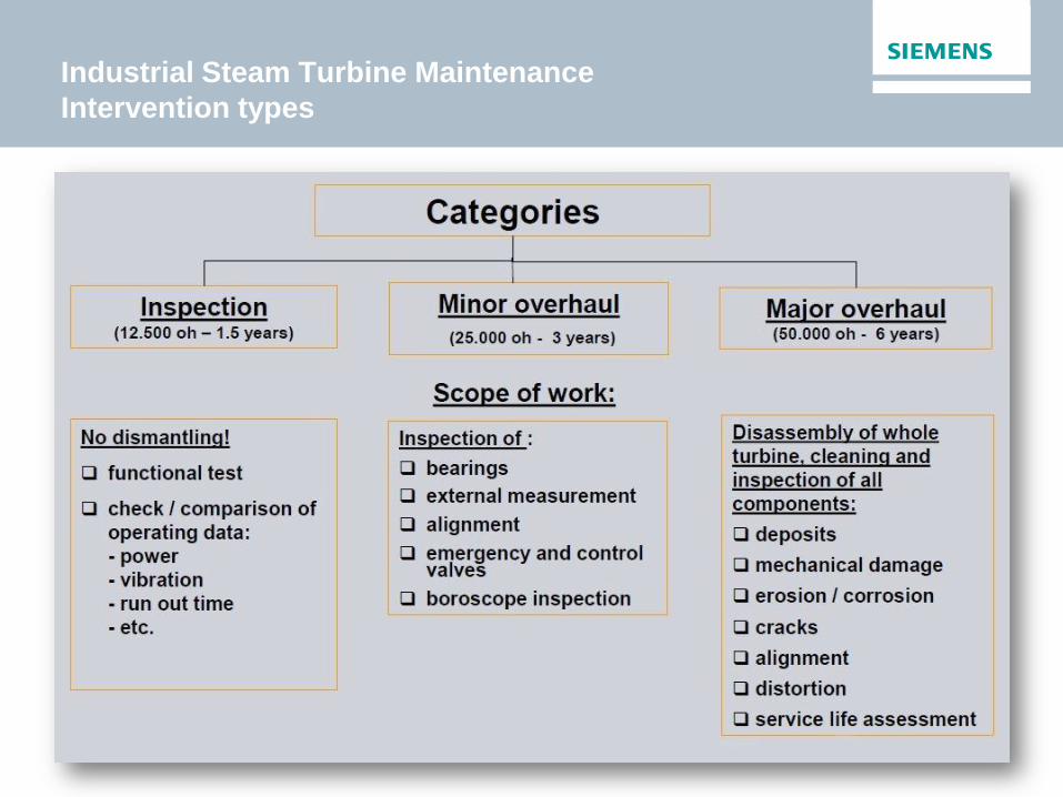
Industrial Steam Turbine Maintenance
Intervention types

Industrial Steam Turbine Maintenance
Organising interventions – Points to consider
• Workscope
• Standard
• Incorporate improvements
• Revamp
• Subcontract or not
• Tools – Equipment – Consumables
• Spare parts
• Manpower – Shiftwork
• Accomodation - Facilities
• Intervention – plant shut down
• Available repair capacity
• Balancing
• Environmental considerations
Industrial Steam Turbine Maintenance
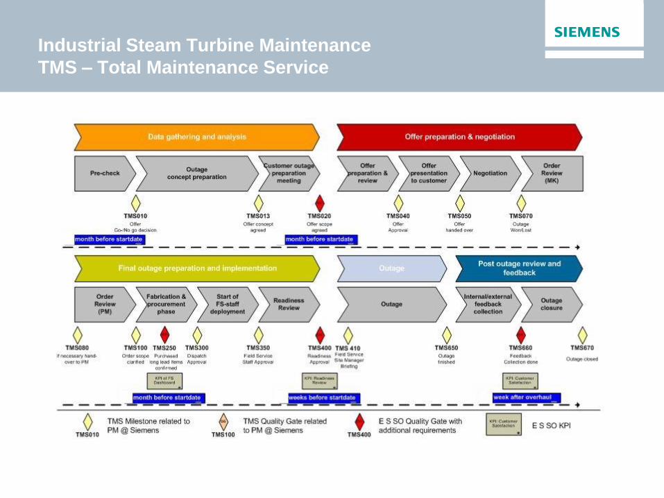
TMS – Total Maintenance Service

Industrial Steam Turbine Maintenance
Revamping of steam turbines
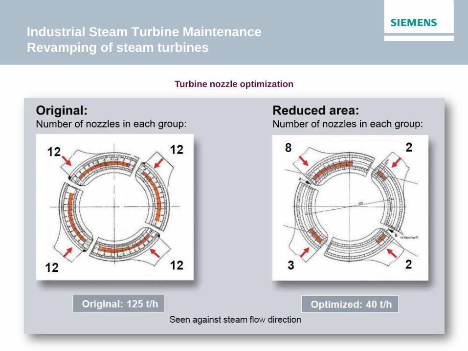
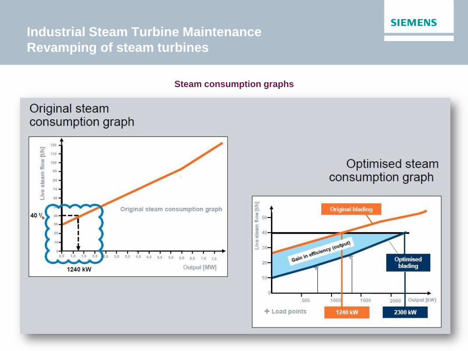
Optimization of the rotor and stator to operate with 60 % less live steam flow
Industrial Steam Turbine Maintenance
Revamping of steam turbines
Turbine nozzle optimization
Industrial Steam Turbine Maintenance
Revamping of steam turbines
Steam consumption graphs

Industrial Steam Turbine Maintenance
Footprints

Questions?

It’s time for a coffee!
Energy audits Walter Hüwels
Siemens Turbine Day – June 3rd 2015

Siemens?
• XXXX
Over 15 years of energy efficiency
consulting experience
Siemens has the largest environmental
portfolio in the world
Broad industry know-how
A name synonymous with high quality
products and solutions
Siemens own sustainability program
delivered 26% primary energy savings
and a 22% CO2 emissions reduction.
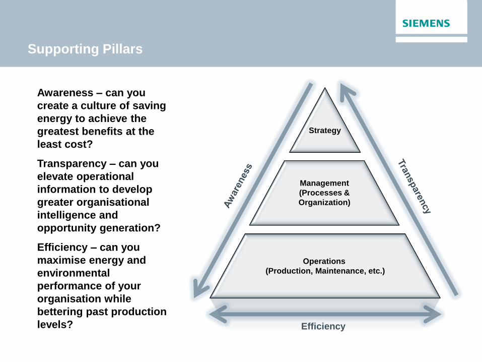
Efficiency
Strategy
Operations
(Production, Maintenance, etc.)
Management
(Processes &
Organization)
Awareness – can you
create a culture of saving
energy to achieve the
greatest benefits at the
least cost?
Transparency – can you
elevate operational
information to develop
greater organisational
intelligence and
opportunity generation?
Efficiency – can you
maximise energy and
environmental
performance of your
organisation while
bettering past production
levels?
Supporting Pillars

Implementation Concept
Concept Assessment Implementation
Opportunity Report
Service
Project Handover
Obtain ISO50001
certification
Develop a strategy,
tools and processes
Management
review
Implement an energy
data management
system
Develop data
gathering concept
Data transparency
review
Implement technical
optimization
measures
Develop an
implementation
concept
Technical
energy audit
Maintain a culture of
awareness
Extract value through
managed services
Maintain for savings
endurance
Awareness
Transparency
Efficiency
Methodology

Awareness
1 2 3 4 5
•Workshop
•Assess and activate management at the start of the
program
•Plant manage r& production-, finance-, HR- and
maintenance managers
•Takes arround 3 hours
•Areas covered :
Leadership, Understanding, Planning, People,
Financial, Supply, Operations&Maintenance,
Plant&equipment, Monitoring&Reporting,
Achievement
•Are they as good as they think they are ?
•Is energy taken in account in all decisions and
processes?
•Overall score from 1 to 5 with 5 being best in class
•But score 1 = Huge potential !
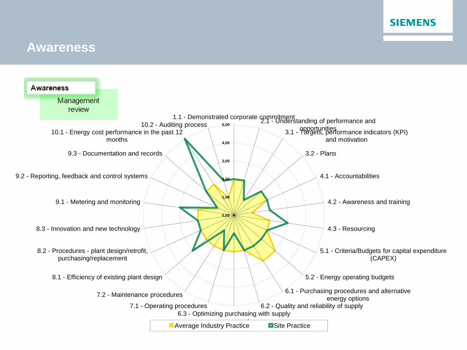
Awareness
0,00
1,00
2,00
3,00
4,00
5,00
1.1 - Demonstrated corporate commitment 2.1 - Understanding of performance and
opportunities 3.1 - Targets, performance indicators (KPI)
and motivation
3.2 - Plans
4.1 - Accountabilities
4.2 - Awareness and training
4.3 - Resourcing
5.1 - Criteria/Budgets for capital expenditure (CAPEX)
5.2 - Energy operating budgets
6.1 - Purchasing procedures and alternative energy options
6.2 - Quality and reliability of supply
6.3 - Optimizing purchasing with supply agreement
7.1 - Operating procedures
7.2 - Maintenance procedures
8.1 - Efficiency of existing plant design
8.2 - Procedures - plant design/retrofit, purchasing/replacement
8.3 - Innovation and new technology
9.1 - Metering and monitoring
9.2 - Reporting, feedback and control systems
9.3 - Documentation and records
10.1 - Energy cost performance in the past 12 months
10.2 - Auditing process
Average Industry Practice Site Practice

Transparency
• Metered data available ?
• Quality of metered data ?
• What is metered / monitored ?
• Definition of KPI’s
• Visualisation of energy distribution
• Availability of reports
• Accessibility of data
• Situational monitoring (before & after implementation
of a project)

Transparency
Installed Meters
Local monitoring system
(Bdata)
Reporting
Remote monitoring system
(Energy Analytics)
Reporting
OR
OR
ISO 50001 requirement

Efficiency
• Collaboration between auditor and plant engineers
• Max.1 week on site
• Report contains as is overview and measures per area :
• Steam, Compressed air, Heating, Cooling,
Processes …
• Measures : description, savings potential (Energy &
GHG), ROI.
• Accuracy :+/- 25% (depending on figures available)
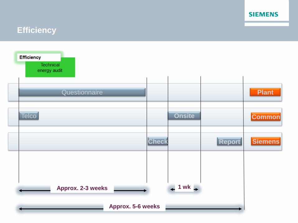
Efficiency
Report
Questionnaire
Approx. 5-6 weeks
Onsite Telco
Approx. 2-3 weeks
Check
Plant
Common
Siemens
1 wk

Europe : EED
Subject matter and scope (Art.
1)
Energy efficiency targets (Art.
3)
Energy efficiency obligation
schemes (Art. 7)
Target Setting
Building renovation (Art. 4)
Exemplary role of public
bodies’ buildings (Art. 5)
Energy efficiency obligation
schemes (Art. 7)
Increasing Energy Efficiency
Energy audits and energy
management systems (Art. 8)
Metering (Art. 9)
Billing information (Art. 10,
11)
Promotion of efficiency in
heating and cooling (Art. 14)
Energy transformation,
transmission and
distribution (Art. 15)
Availability of qualification,
accreditation and certification
schemes (Art. 16)
Information and training (Art.
17)
Energy services (Art 18)
Horizontal
Other measures to promote
energy efficiency (Art. 19)
Energy Efficiency National
Fund, Financing and Technical
Support (Art. 20)
Energy audits and energy
management systems (Art. 8)

Europe : EED
Article 8
Large enterprises have to conduct an energy audit (EA) every 4 years and are
exempted from this requirement if they are implementing an energy
or environmental management system (EnMS) by 5 December 2015
Energy Management System (EnMS) Energy Audit
ISO50001 compliant EnMS include annual Technical Analyses as part of the Energy Planning Procedure
Nonconformities,
correction, corrective
and preventive actions
Checking
Internal audit
Monitoring,
measurement
and analysis
Management
review
Continual
improvement
Implementation
and operation
Energy planning
Energy policy
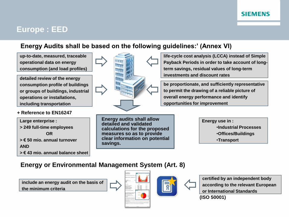
Europe : EED
Energy Audits shall be based on the following guidelines:’ (Annex VI)
Energy or Environmental Management System (Art. 8)
up-to-date, measured, traceable
operational data on energy
consumption (and load profiles)
detailed review of the energy
consumption profile of buildings
or groups of buildings, industrial
operations or installations,
including transportation
life-cycle cost analysis (LCCA) instead of Simple
Payback Periods in order to take account of long-
term savings, residual values of long-term
investments and discount rates
be proportionate, and sufficiently representative
to permit the drawing of a reliable picture of
overall energy performance and identify
opportunities for improvement
Energy audits shall allow detailed and validated calculations for the proposed measures so as to provide clear information on potential savings.
certified by an independent body
according to the relevant European
or International Standards
include an energy audit on the basis of
the minimum criteria
+ Reference to EN16247
(ISO 50001)
Energy use in :
•Industrial Processes
•Offices/Buildings
•Transport
Large enterprise :
> 249 full-time employees
OR
> € 50 mio. annual turnover
AND
> € 43 mio. annual balance sheet
Energy project list (1)
Paper production technology
2003-2005 2006 2007 2008 2009
Energy project list (2)
2010 2011 2012 2013 2014
Energy project list (3)
2015 2016 2017 2018 2019

Questions?
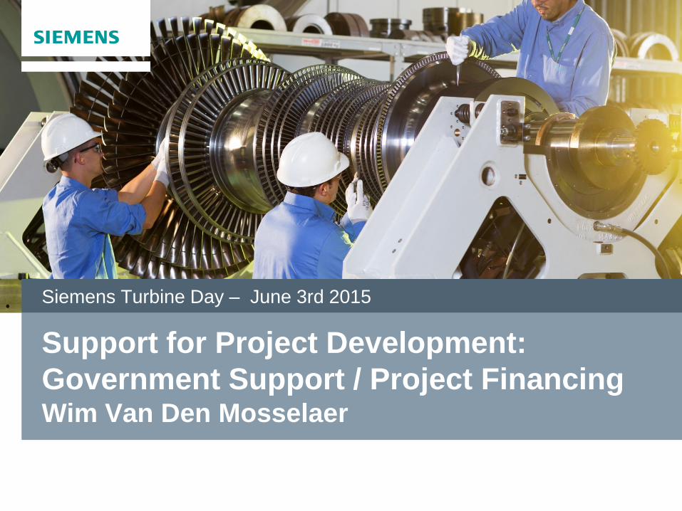
Support for Project Development:
Government Support / Project Financing Wim Van Den Mosselaer
Siemens Turbine Day – June 3rd 2015

Support for project development – Government Support
PRIMARY ENERGY SAVINGS
Source: WKK-Handboek Cogen Vlaanderen v2015.1_finaal
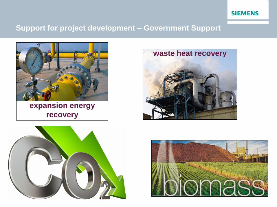
Support for project development – Government Support
waste heat recovery
expansion energy
recovery
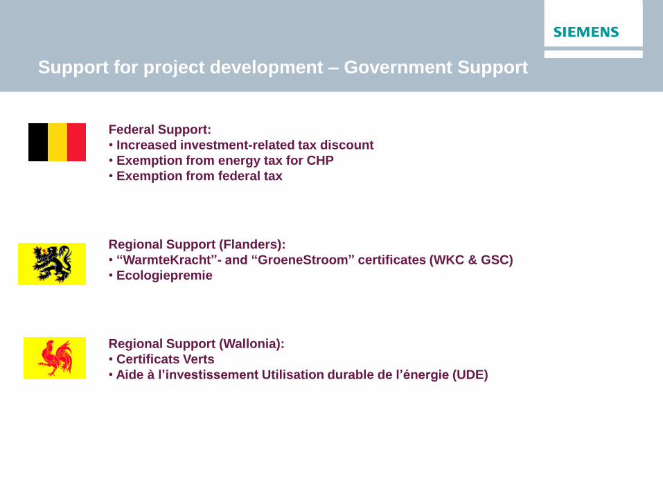
Support for project development – Government Support
Federal Support:
• Increased investment-related tax discount
• Exemption from energy tax for CHP
• Exemption from federal tax
Regional Support (Flanders):
• “WarmteKracht”- and “GroeneStroom” certificates (WKC & GSC)
• Ecologiepremie
Regional Support (Wallonia):
• Certificats Verts
• Aide à l’investissement Utilisation durable de l’énergie (UDE)
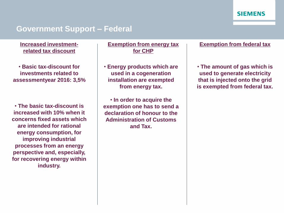
Government Support – Federal
Increased investment-
related tax discount
• Basic tax-discount for
investments related to
assessmentyear 2016: 3,5%
• The basic tax-discount is
increased with 10% when it
concerns fixed assets which
are intended for rational
energy consumption, for
improving industrial
processes from an energy
perspective and, especially,
for recovering energy within
industry.
Exemption from energy tax
for CHP
• Energy products which are
used in a cogeneration
installation are exempted
from energy tax.
• In order to acquire the
exemption one has to send a
declaration of honour to the
Administration of Customs
and Tax.
Exemption from federal tax
• The amount of gas which is
used to generate electricity
that is injected onto the grid
is exempted from federal tax.
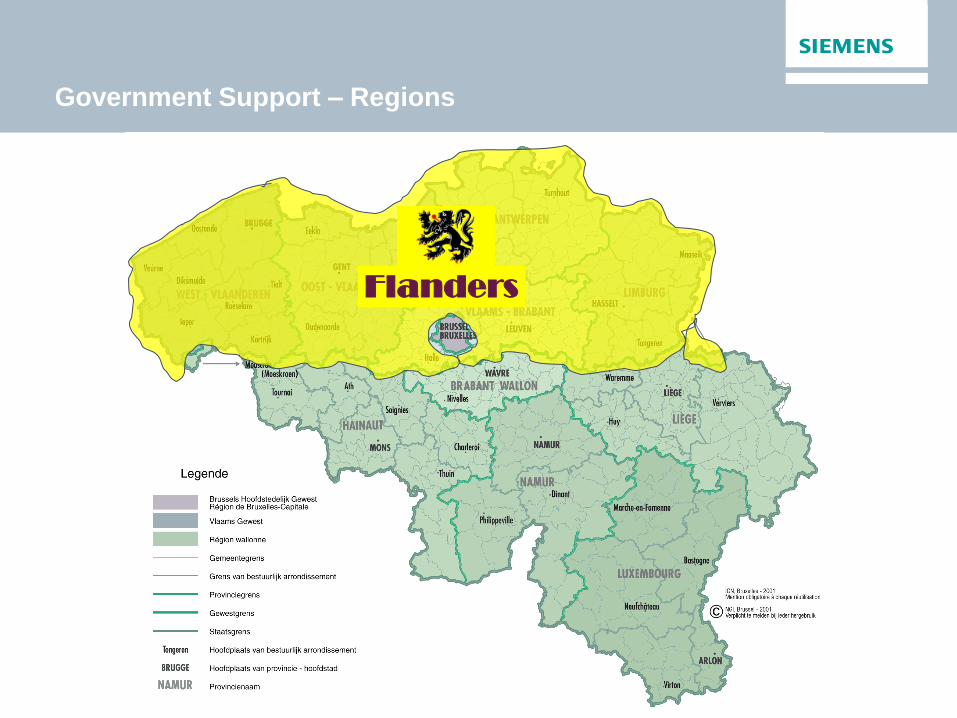
Government Support – Regions
Flanders

CHP installation
owner
Electricity
supplier Regulator
or penalty
certificates
Assigning
certificates
Free
Market
Obligation: quota
Government Support – Flanders Region
“WKC” : “WarmteKrachtCertificaten” Market Principle:
Source: WKK-Handboek Cogen Vlaanderen v2015.1_finaal

Government Support – Flanders Region
“WKC” : “WarmteKrachtCertificaten” Market Principle:
CHP installation
owner
Electricity
supplier Regulator
or penalty
certificates
Assigning
certificates
Open
Market
Obligation: quota
Free
Market
Gridoperator
Guaranteed
compensation
Source: WKK-Handboek Cogen Vlaanderen v2015.1_finaal
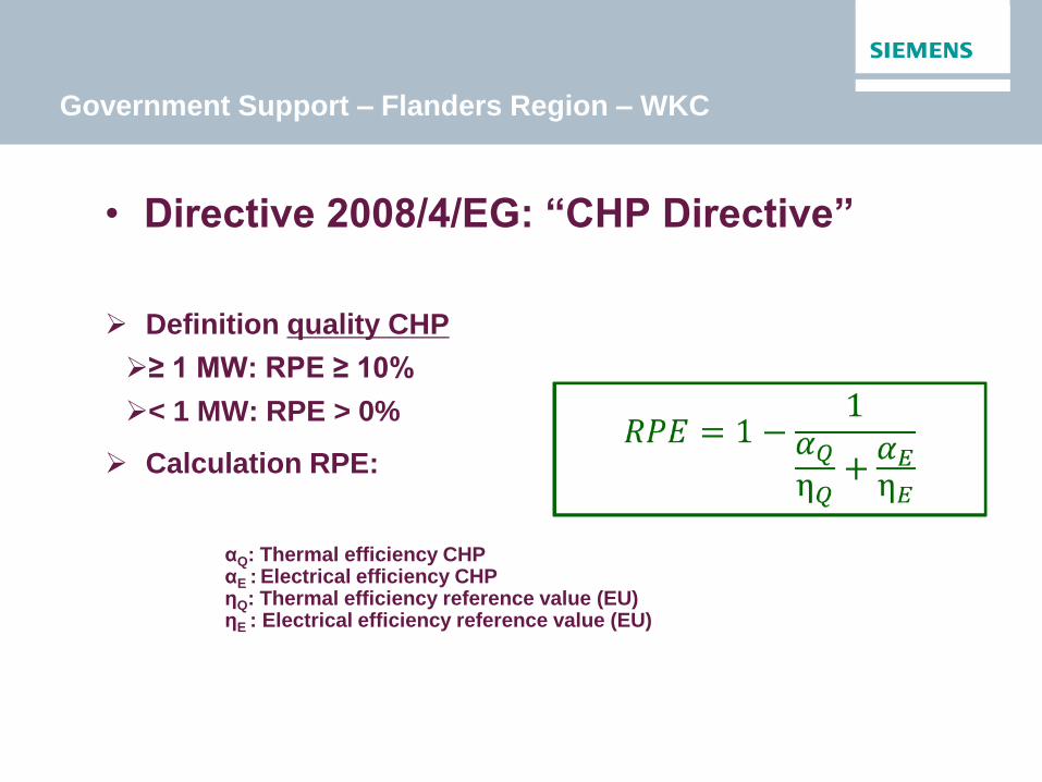
Government Support – Flanders Region – WKC
• Directive 2008/4/EG: “CHP Directive”
Definition quality CHP
≥ 1 MW: RPE ≥ 10%
< 1 MW: RPE > 0%
Calculation RPE:
αQ: Thermal efficiency CHP αE : Electrical efficiency CHP ηQ: Thermal efficiency reference value (EU) ηE : Electrical efficiency reference value (EU)

Government Support – Flanders Region – WKC
• Directive 2008/4/EG: “CHP Directive”
Definition quality CHP
≥ 1 MW: RPE ≥ 10%
< 1 MW: RPE > 0%
Calculation RPE:
36/136 26% > 10%
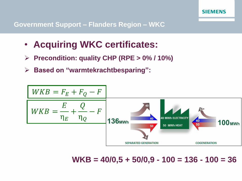
Government Support – Flanders Region – WKC
• Acquiring WKC certificates:
Precondition: quality CHP (RPE > 0% / 10%)
Based on “warmtekrachtbesparing”:
WKB = 40/0,5 + 50/0,9 - 100 = 136 - 100 = 36
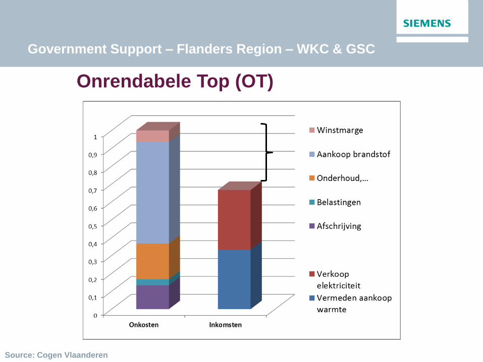
Government Support – Flanders Region – WKC & GSC
Onrendabele Top (OT)
Source: Cogen Vlaanderen
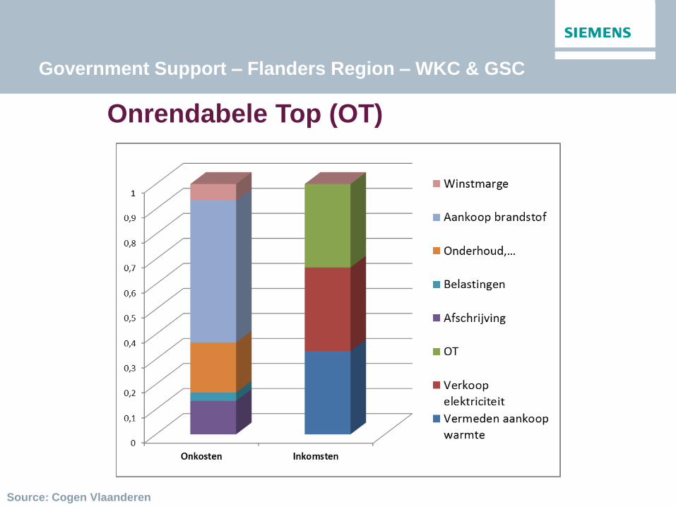
Government Support – Flanders Region – WKC & GSC
Onrendabele Top (OT)
Source: Cogen Vlaanderen
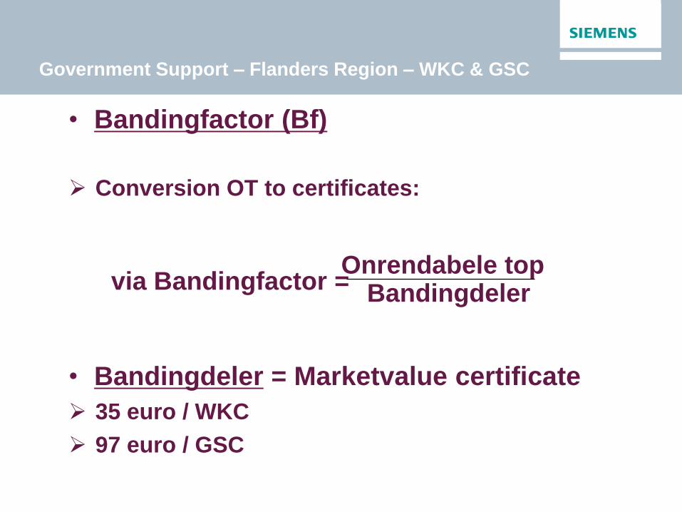
Government Support – Flanders Region – WKC & GSC
• Bandingfactor (Bf)
Conversion OT to certificates:
via Bandingfactor =
• Bandingdeler = Marketvalue certificate
35 euro / WKC
97 euro / GSC
Onrendabele top Bandingdeler

Government Support – Flanders Region – WKC & GSC
• Real financial support:
Combined Heat and Power:
WKBnetto x bandingfactor x marketvalue
31€/WKC certificate = minimumprice (grid operator)
Green Electricity:
GSCnetto x bandingfactor x marketvalue
93€/GSC certificate = minimumprice (grid operator)
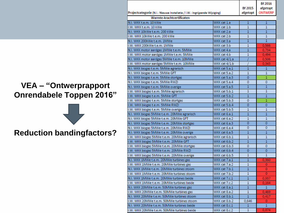
VEA – “Ontwerprapport
Onrendabele Toppen 2016”
Reduction bandingfactors?
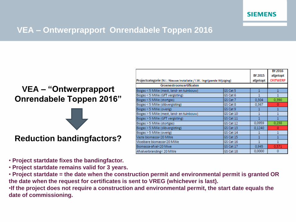
VEA – Ontwerprapport Onrendabele Toppen 2016
VEA – “Ontwerprapport
Onrendabele Toppen 2016”
Reduction bandingfactors?
• Project startdate fixes the bandingfactor.
• Project startdate remains valid for 3 years.
• Project startdate = the date when the construction permit and environmental permit is granted OR
the date when the request for certificates is sent to VREG (whichever is last).
•If the project does not require a construction and environmental permit, the start date equals the
date of commissioning.
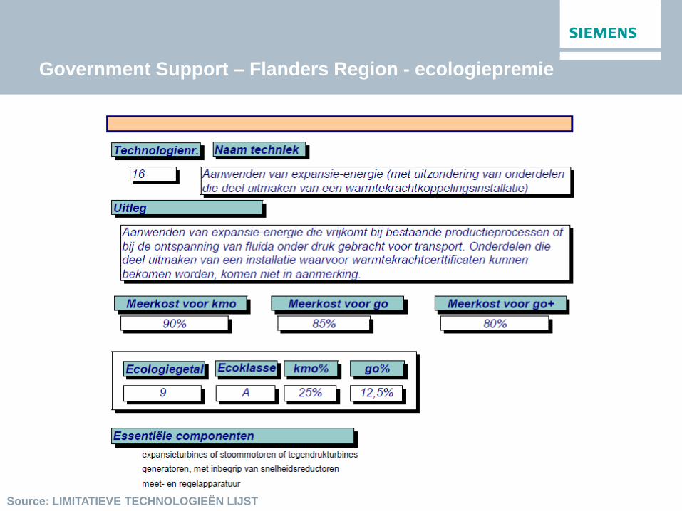
Government Support – Flanders Region - ecologiepremie
Source: LIMITATIEVE TECHNOLOGIEËN LIJST

Government Support – Regions
Wallonia
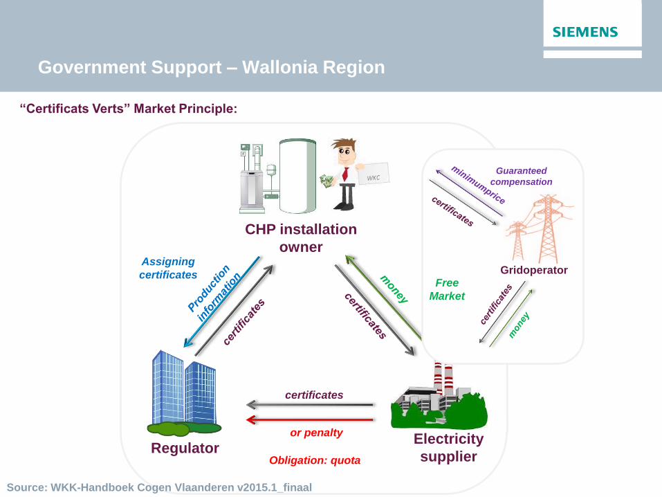
Government Support – Wallonia Region
“Certificats Verts” Market Principle:
CHP installation
owner
Electricity
supplier Regulator
or penalty
certificates
Assigning
certificates
Open
Market
Obligation: quota
Free
Market
Gridoperator
Guaranteed
compensation
Source: WKK-Handboek Cogen Vlaanderen v2015.1_finaal
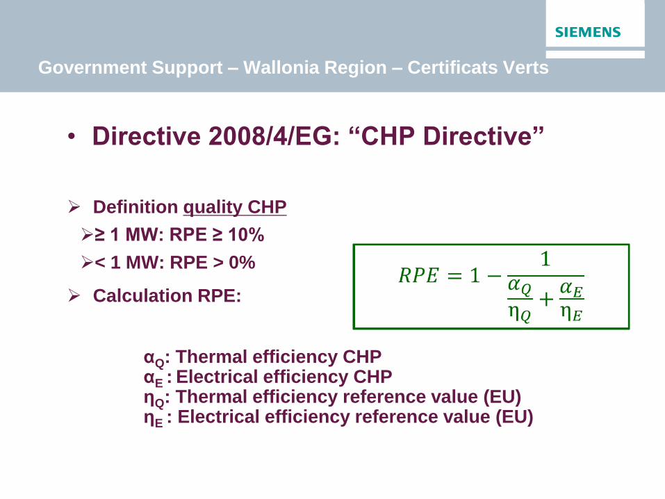
Government Support – Wallonia Region – Certificats Verts
• Directive 2008/4/EG: “CHP Directive”
Definition quality CHP
≥ 1 MW: RPE ≥ 10%
< 1 MW: RPE > 0%
Calculation RPE:
αQ: Thermal efficiency CHP αE : Electrical efficiency CHP ηQ: Thermal efficiency reference value (EU) ηE : Electrical efficiency reference value (EU)

• CO2 reduction compared to reference values:
CO2 reduction: [kgCO2/MWhe]
with Eref: CO2 of the reference electricity production [kgCO2/MWh]
Q: CO2 of the reference heat production
Qf: CO2 of the reference cold production
F: CO2 emission of the CHP unit
• Number of Green Certificates:
CV = tCV x Eenp
tCV = min (2,5 ; kCO2 x kECO)
Government Support – Wallonia Region – Certificats Verts
FQQEG fref
Source: COMMISSION WALLONNE POUR L’ÉNERGIE
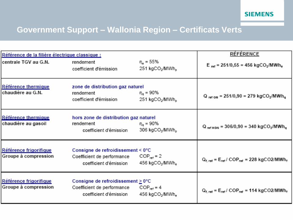
Government Support – Wallonia Region – Certificats Verts
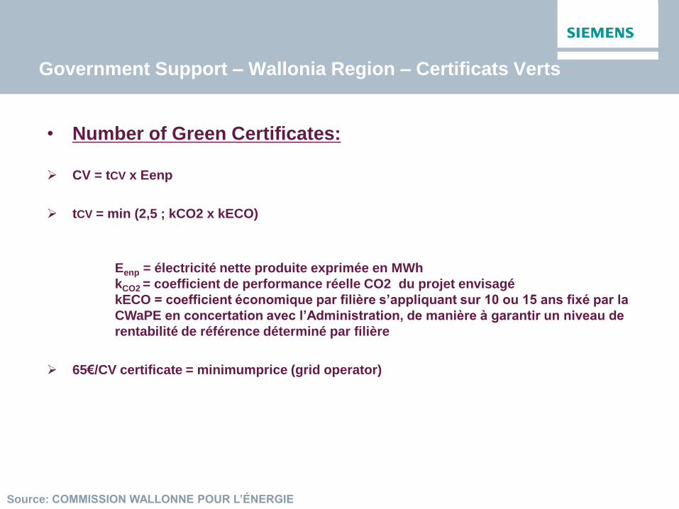
Government Support – Wallonia Region – Certificats Verts
• Number of Green Certificates:
CV = tCV x Eenp
tCV = min (2,5 ; kCO2 x kECO)
Eenp = électricité nette produite exprimée en MWh
kCO2 = coefficient de performance réelle CO2 du projet envisagé
kECO = coefficient économique par filière s’appliquant sur 10 ou 15 ans fixé par la
CWaPE en concertation avec l’Administration, de manière à garantir un niveau de
rentabilité de référence déterminé par filière
65€/CV certificate = minimumprice (grid operator)
Source: COMMISSION WALLONNE POUR L’ÉNERGIE
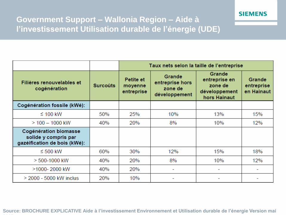
Government Support – Wallonia Region – Aide à
l’investissement Utilisation durable de l’énergie (UDE)
Source: BROCHURE EXPLICATIVE Aide à l’investissement Environnement et Utilisation durable de l’énergie Version mai
2015

Government Support – Wallonia Region – Aide à
l’investissement Utilisation durable de l’énergie (UDE)
Source: BROCHURE EXPLICATIVE Aide à l’investissement Environnement et Utilisation durable de l’énergie Version mai
2015
• Conditions:
Excluded activity sectors:
Extraction of energy products, nuclear, production and distribution of power and
water, healthcare, leisure and culture, product distribution.
Quality CHP
Investment = minimum 25.000€
Investment support limited to the extra costs:
Compared to a reference production installation
Support:
Small & Medium Scale Enterprises (PME): 50%
Large Scale Enterprises: 20% (+5% if in development zone (+10% in Hainaut))
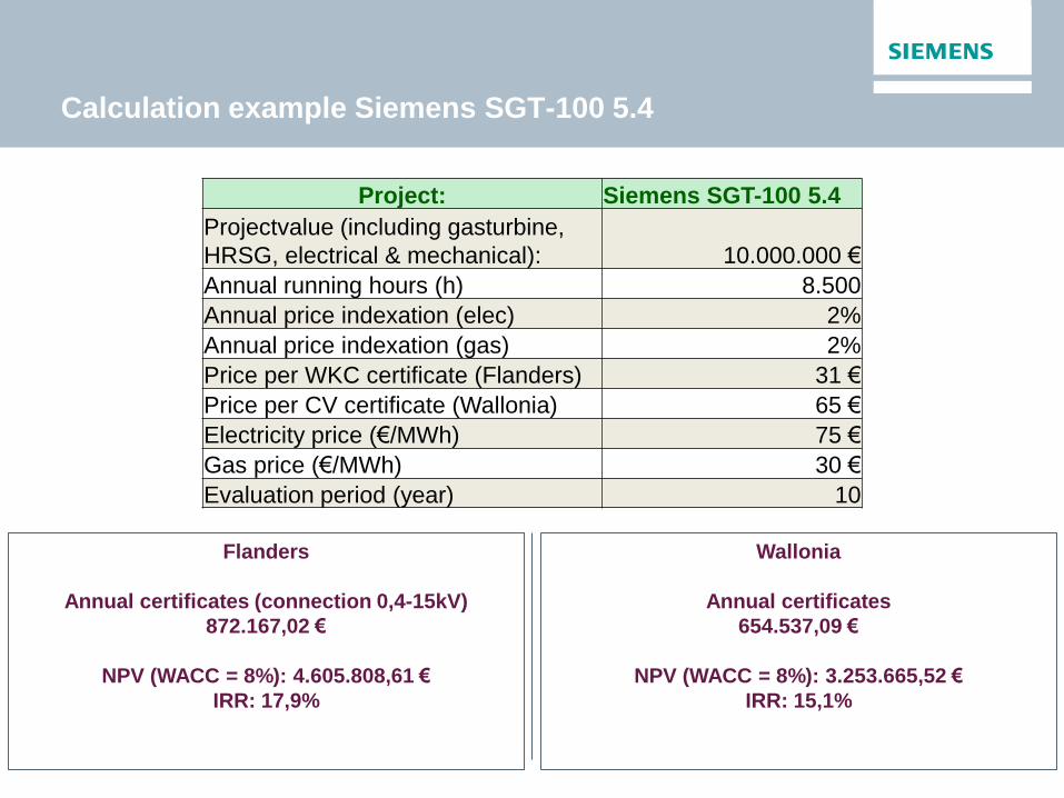
Calculation example Siemens SGT-100 5.4
Project: Siemens SGT-100 5.4
Projectvalue (including gasturbine,
HRSG, electrical & mechanical): 10.000.000 €
Annual running hours (h) 8.500
Annual price indexation (elec) 2%
Annual price indexation (gas) 2%
Price per WKC certificate (Flanders) 31 €
Price per CV certificate (Wallonia) 65 €
Electricity price (€/MWh) 75 €
Gas price (€/MWh) 30 €
Evaluation period (year) 10
Flanders
Annual certificates (connection 0,4-15kV)
872.167,02 €
NPV (WACC = 8%): 4.605.808,61 €
IRR: 17,9%
Wallonia
Annual certificates
654.537,09 €
NPV (WACC = 8%): 3.253.665,52 €
IRR: 15,1%
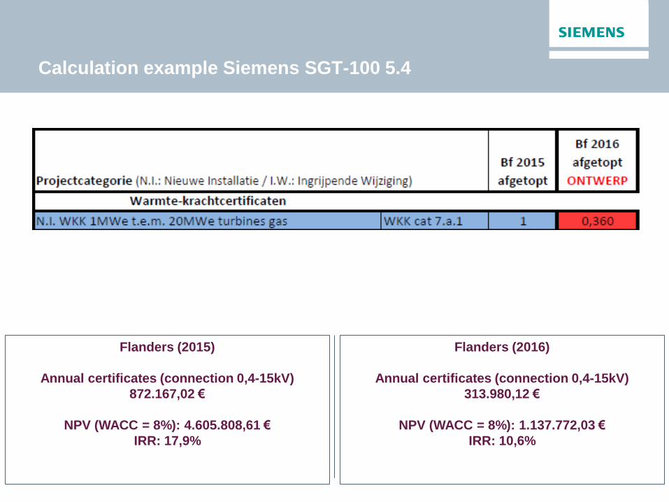
Calculation example Siemens SGT-100 5.4
Flanders (2015)
Annual certificates (connection 0,4-15kV)
872.167,02 €
NPV (WACC = 8%): 4.605.808,61 €
IRR: 17,9%
Flanders (2016)
Annual certificates (connection 0,4-15kV)
313.980,12 €
NPV (WACC = 8%): 1.137.772,03 €
IRR: 10,6%
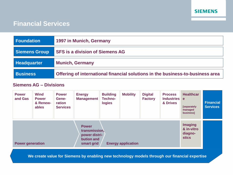
Financial Services
1997 in Munich, Germany
SFS is a division of Siemens AG
Munich, Germany
Offering of international financial solutions in the business-to-business area
Foundation
Siemens Group
Headquarter
Business
Siemens AG – Divisions
Power
and Gas
Wind
Power
& Renew-
ables
Power
Gene-
ration
Services
Energy
Management
Building
Techno-
logies
Mobility Digital
Factory
Process
Industries
& Drives
Healthcar
e
[separately
managed
business]
Financial
Services
Imaging
& in-vitro
diagno-
stics
Power generation
Power
transmission,
power distri-
bution and
smart grid Energy application
We create value for Siemens by enabling new technology models through our financial expertise
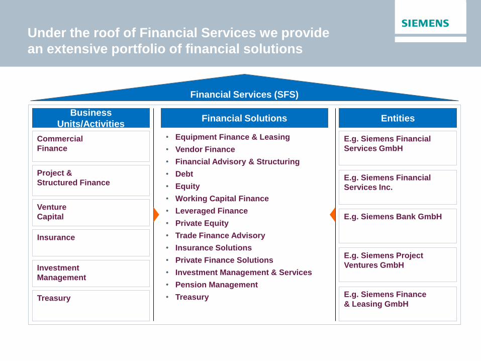
Under the roof of Financial Services we provide
an extensive portfolio of financial solutions
Commercial
Finance
Entities
Financial Services (SFS)
Financial Solutions Business
Units/Activities
Project &
Structured Finance
E.g. Siemens Bank GmbH
Venture
Capital
Insurance
Investment
Management
E.g. Siemens Financial
Services GmbH
E.g. Siemens Financial
Services Inc.
Treasury
E.g. Siemens Project
Ventures GmbH
E.g. Siemens Finance
& Leasing GmbH
• Equipment Finance & Leasing
• Vendor Finance
• Financial Advisory & Structuring
• Debt
• Equity
• Working Capital Finance
• Leveraged Finance
• Private Equity
• Trade Finance Advisory
• Insurance Solutions
• Private Finance Solutions
• Investment Management & Services
• Pension Management
• Treasury
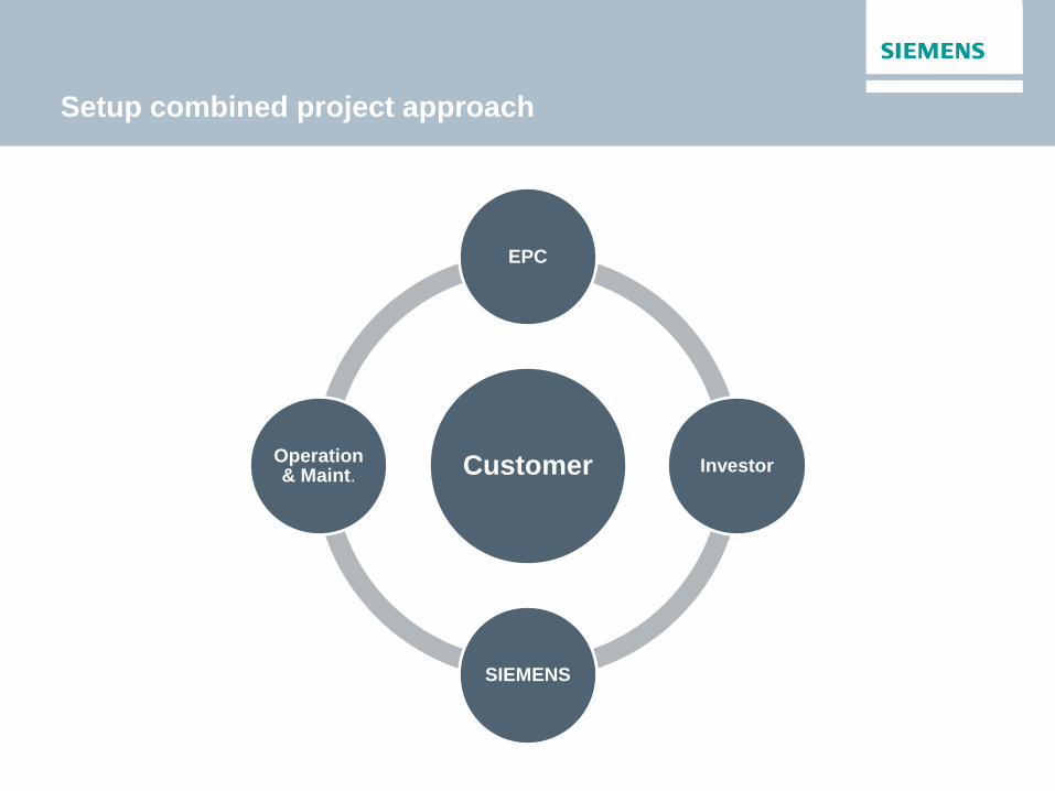
Setup combined project approach
Customer
EPC
Investor
SIEMENS
Operation & Maint.
Information Sources
http://www.cogenvlaanderen.be/
http://www.cwape.be/
http://www.agentschapondernemen.be/sites/default/files/documenten/ep_ltl-epplus-2014-11-
type.pdf
http://www.energiesparen.be/verhoogdeinvesteringsaftrek
http://eemnesser.nl/wp-content/uploads/2015/01/CO2-reductie-IndustrieBlogjpg.jpg
http://www.ethosgen.com/wp-content/uploads/2013/09/139875.jpg
https://oecotextiles.files.wordpress.com/2011/05/biomass3.jpg
http://www.spilling.info/images/gasexpansion/Gasexpansion_Titel.jpg

Questions?
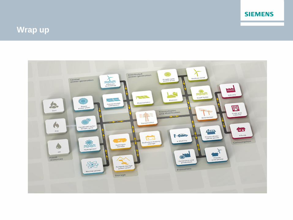
Wrap up
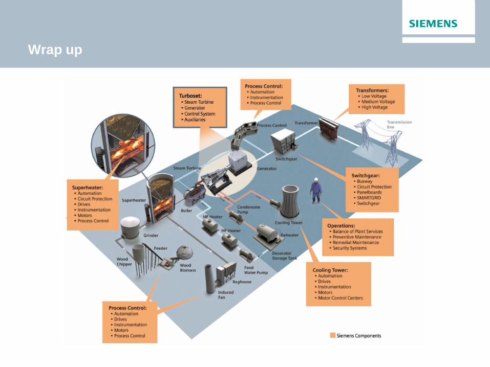
Wrap up

Let’s have a drink!