presentation cloud infrastructure launch – what’s new
TRANSCRIPT

© 2009 VMware Inc. All rights reserved
Cloud Infrastructure Launch – What’s New Your Cloud. Intelligent Virtual Infrastructure. Delivered Your Way. Michele Apa
Senior Systems Engineer

2
Agenda
Cloud Infrastructure 5 • vSphere 5 • vCenter 5
• vCenter Site Recovery Manager 5
vCloud Director 1.5 VCOPs

3
The New IT Landscape: Promise & Challenge
Existing Apps New Enterprise Apps SaaS Apps
Existing Datacenters Public Cloud Services
A More Flexible, Efficient Infrastructure
• Exploiting modern, cost-effective hardware
• Creating & spanning both internal and external resource pools
New Generation of Enterprise Apps • Combining the social, mobile experience
with enterprise requirements
Empowered, Secure, Mobile Workforce
• Any app on any device, anytime, anywhere – securely!

4
The New IT Landscape: Promise & Challenge
Existing Apps New Enterprise Apps SaaS Apps
Existing Datacenters Public Cloud Services
The Challenge for IT:
Weave all this together into a cohesive,
secure, compliant whole

5
The Approach in the IT Management
Traditional IT Management
Services and assets tied together in complex, brittle, vertical stacks that are hard to change and manage
Business agility suffers
IT able to keep up with speed of the business
Management in the new Era
Service components are abstracted and sourced from dynamic resource pools with horizontal layers loosely bound into services

6
Key Constituents for Infrastructure and Management
Desired Outcome
Balance operating expense and innovation
Seamless extension of existing infrastructure interoperable with new technology
Maximize operational efficiencies with more dynamic lights-out environment
Head of Infrastructure
Head of Operations
Head of Architecture
Care About
How do I build the right infrastructure to deliver business value yet still
keep the lights on?
What kind of infrastructure should I design for today and
tomorrow’s needs? Will it work with our current
infrastructure?
How do I keep OpEx down and still deliver
high quality of service?

7
APP APP APP
VMware Infrastructure and Management Delivers the Infrastructure of the Future
Optimized for business critical workloads Highly dynamic, scalable and adaptive
Built-in intelligence to shift to new IT management paradigm
Flexible Computing Model
VMware Cloud Infrastructure and Management
Physical Servers Failed Server
APP APP
Resource Pools
Tier 1 Tier 2 Tier 3
Intelligent Virtual Infrastructure. Delivered Your Way The Foundation for Your Cloud
Respond and Alert vs.
Alert and Respond Hybrid Cloud
Private Cloud
Public Cloud
Bridge

8
The Cloud Infrastructure 5

9
Existing Datacenters Public Cloud Services
Existing Apps New Enterprise Apps SaaS Apps
Three Core Focus Areas
Evolve the Infrastructure
Modernize Application Development
Re-think End-User Computing

10
In 2010 VMware Unveiled a Complete Hybrid Cloud Stack…
vCloud Director
vShield Security
vCenter Management
vSphere vSphere vSphere

11
Complete Hybrid Cloud Stack
Compute
Storage
Network
Leverage virtualization to transform physical silos into elastic, virtual capacity Increase automation through built-in intelligent policy management Move from static, physical security to dynamic, embedded security Enable secure, self-service to pre-defined IT services, with pay-for-use
Organization: Marketing Organization: Finance
Virtual Datacenters Catalogs Virtual Datacenters Catalogs Users & Policies Users & Policies

12
vSphere vSphere vSphere
vCloud Director
vShield Security
vCenter Management
vCloud Director 1.5
vShield 5.0
vCenter Operations 1.0 vCenter SRM 5.0
vSphere 5.0
Cloud Infrastructure Launch (vSphere, vCenter, vShield, vCloud Director)
In 2011 VMware is Introducing a Major Upgrade of the Entire Cloud Infrastructure Stack
New

13
vSphere 5: Accelerating the Path to 100% Virtualization
IOPS
Network
Memory
CPU
VMware vSphere4
300,000
30
256
8
VMware Inf. 3
100,000
9
64
4
VMware vSphere 5
1,000,000
>36
1,000
32
ESX 2
7,000
.9
3.6
2
ESX 1
<5,000
<.5
2
1 (VCPUs)
(Gb/s)
(GB per VM)
4x
14
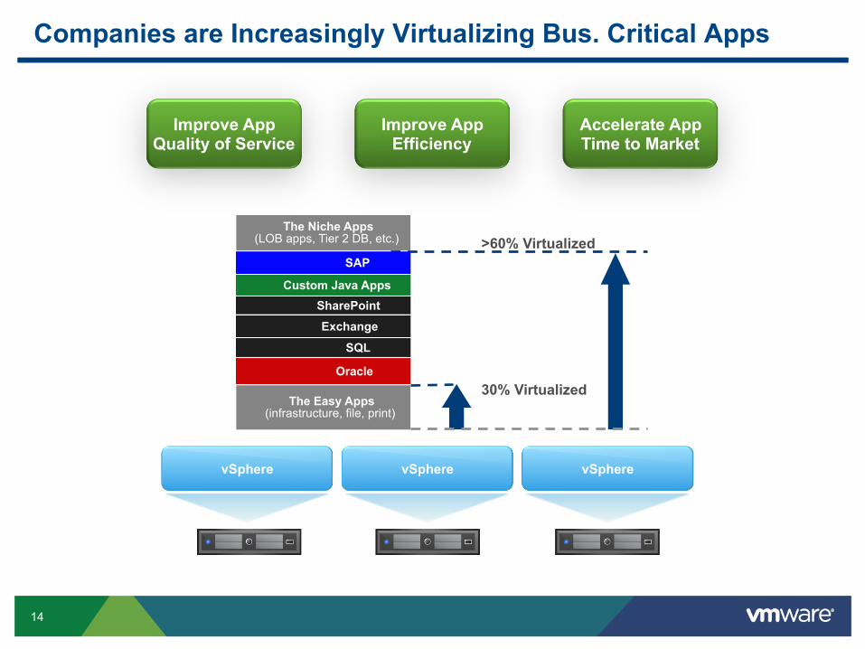
Companies are Increasingly Virtualizing Bus. Critical Apps
The Niche Apps (LOB apps, Tier 2 DB, etc.)
The Easy Apps (infrastructure, file, print)
Exchange
SQL
Oracle
SharePoint Custom Java Apps
30% Virtualized
>60% Virtualized SAP
Accelerate App Time to Market
Improve App Quality of Service
Improve App Efficiency
vSphere vSphere vSphere

15
vSphere 5 What’s new

16
ESXi is the Trusted Place to Run Business Critical Applications
• vSphere 5.0 exclusively utilizes the thin ESXi hypervisor: 144MB footprint versus 2GB for VMware ESX with the service console
vSphere ESXi
• Smaller security footprint
• Streamlined deployment and configuration
• Simplified patching and updating model
Overview
Benefits
vSphere ESX

17
ESXi 5.0 Firewall Features
Capabilities • ESXi 5.0 has a new firewall engine which is not based on iptables. • The firewall is service oriented, and is a stateless firewall.
• Users have the ability to restrict access to specific services based on IP address/Subnet Mask.
Management • The GUI for configuring the firewall on ESXi 5.0 is similar to that used with the
classic ESX firewall — customers familiar with the classic ESX firewall should not have any difficulty with using the ESXi 5.0 version.
• There is a new esxcli interface (esxcfg-firewall is deprecated in ESXi 5.0). • There is Host Profile support for the ESXi 5.0 firewall.
• Customers who upgrade from Classic ESX to ESXi 5.0 will have their firewall settings preserved.

18
UI: Security Profile
The ESXi Firewall can be managed via the vSphere client. Through the Configuration > Security Profile, one can observe the
Enabled Incoming/Outgoing Services, the Opened Port List for each service & the Allowed IP List for each service.

19
ESXi Image Deployment
Challenges • Standard ESXi image from VMware download site is sometimes limited
• Doesn’t have all drivers or CIM providers for specific hardware • Doesn’t contain vendor specific plug-in components
? Standard ESXi ISO
• Base providers • Base drivers
Missing CIM
provider
Missing driver

20
ESXi Image Deployment: Composition of an ESXi Image
Core Hypervisor
CIM Providers
Plug-in Components
Drivers

21
Capacity: vSphere 5 with Autodeploy
Time: 30 mins
Total time: 20 Hours!
...Repeat 37 more times…
Total time: 10 Minutes!
Before After
Time: 30 mins Time: 30 mins
vSphere vSphere vSphere vSphere

22
Auto Deploy: What is?
New host deployment method introduced in vSphere 5.0 • Based on PXE Boot • Works with Image Builder, vCenter Server, and Host Profiles
• How it works: • PXE boot the server • ESXi image profile loaded into host memory via Auto Deploy Server • Configuration applied using Answer File / Host Profile • Host placed/connected in vCenter
• Benefits • No boot disk • Quickly and easily deploy large numbers of ESXi hosts • Share a standard ESXi image across many hosts • Host image decoupled from the physical server
• Recover host w/out recovering hardware or having to restore from backup

23
No Boot Disk? Where does it go?
What Is Auto Deploy
Boot Disk
All information on the state of the host is stored off the
host in vCenter
Platform Composition: ESXi base, drivers, CIM providers, …
Configuration: networking, storage, date/time, firewall, admin password, …
Running State: VM Inventory, HA state, License, DPM configuration
Event Recording: log files, core dump

24
No Boot Disk? Where does it go?
Boot Disk
Image Profile
Host Profile
vCenter Server
Add-on Components
What Is Auto Deploy
Platform Composition: ESXi base, drivers, CIM providers, …
Configuration: networking, storage, date/time, firewall, admin password, …
Running State: VM Inventory, HA state, License, DPM configuration
Event Recording: log files, core dump

25
Performance

26
Technical Barriers to 100% Virtualization Have Been Falling
Application’s Performance Requirements
% o
f App
licat
ions
95% of Apps Require
IOPS
Network
Memory
CPU
< 10,000
<2.4 Mb/s
< 4 GB at peak
1 to 2 CPUs
VMware vSphere 4
300,000
30 Gb/s
256 GB per VM
8 VCPUs
VMware Inf.
100,000
9 Gb/s
16/64 GB per VM
4 VCPUs
VMware vSphere 5
1,000,000
>36Gb/s
1,000 GB per VM
32 VCPUs
ESX 2
7,000
.9 Gb/s
3.6 GB per VM
2 VCPUs
ESX 1
<5,000
<.5Gb/s
2 GB per VM
1 VCPUs
3.0/3.5

27
New Virtual Machine Features
vSphere 5.0 supports the industry’s most capable virtual machines
Other new features
• UI for multi-core virtual CPUs
• Extended VMware Tools compatibility
• Support for Mac OS X servers
Broader Device Coverage
• Client-connected USB devices
• USB 3.0 devices • Smart Card Readers for
VM Console Access
• VM BIOS boot order config API and PowerCLI interface
• EFI BIOS
• 3D graphics Richer Desktop
Experience
• 32 virtual CPUs per VM
• 1TB RAM per VM • 4x previous capabilities! VM Scalability
Items which require HW version 8 in orange

28
Networking

29
New Networking Features
Two broad categories of features Network Discovery and Visibility/Monitoring features
• LLDP • NetFlow
• Port Mirror
I/O Consolidation (10 Gig) related features • New traffic types
• User Defined Network Resource Pool (VM traffic) • Host Based Replication traffic
• 802.1p Tagging (QoS)

30
What Is NetFlow?
NetFlow is a networking protocol that collects IP traffic information as records and sends them to third party collectors such as CA NetQoS, NetScout etc.
VDS
VM A VM B
trunk
Physical switch Collector
The Collector/Analyzer report on various information such as: • Current top flows consuming the most bandwidth • Which flows are behaving irregularly • Number of bytes a particular flow has sent and received in the past 24 hours
NetFlow session
Host
VM traffic
Legend :

31
NetFlow Usage
NetFlow helps customers monitor the application flows and measure application performance overtime.
It also helps in capacity planning and ensuring that I/O Network resources are utilized appropriately by different applications.
NetFlow capability in vSphere infrastructure provides complete visibility into virtual infrastructure traffic. • Inter-VM traffic on the same hosts • Intra-VM traffic across hosts
• VM-to-Physical Infrastructure traffic
This visibility into virtual infrastructure traffic allows customer to • Perform Security and Compliance analysis
• Do Profiling and Billing
• Perform Intrusion Detection and Prevention, Networking Forensics

32
What Is Port Mirroring ?
Port Mirroring is the capability on a network switch to send a copy of network packets seen on a switch port to a network monitoring device connected on another switch port.
Port Mirroring is also referred to as SPAN (Switched Port Analyzer) on Cisco Switches.
Port Mirroring overcomes the limitation of promiscuous mode. • By providing granular control on which traffic can be monitored
• Ingress Source • Egress Source
Helps in troubleshooting network issue by providing access to: • Inter-VM traffic
• Intra-VM traffic

33
Performance: vSphere 5 with Network and Storage I/O Controls
VIP

34
Performance: vSphere 5 with Network and Storage I/O Controls
VIP “Noisy Neighbor”
Granular IO service level guarantees

35
What Is Network I/O Control (NETIOC)?
Network I/O control is a traffic management feature of vSphere Distributed Switch (vDS).
In consolidated I/O (10 gig) deployments, this feature allows customers to: • Allocate Shares and Limits to different traffic types. • Provide Isolation
• One traffic type should not dominate others
• Guarantee Service Levels when different traffic types compete
Enhanced Network I/O Control — vSphere 5.0 builds on previous versions of Network I/O Control feature by providing: • User-defined network resource pools
• New Host Based Replication Traffic Type
• QoS tagging

36
NETIOC VM Groups
Network I/O Control
Total BW = 20 Gig
10 GigE
VMware vNetwork Distributed Switch
VM
RG
1
VM
RG
2
VM
RG
3 V
M
vMot
ion
iSC
SI
FT
NFS
HB
R
Confidential U
ser D
efin
ed R
P
VMRG1 VMRG2 VMRG3

37
Storage

38
What is Storage DRS?
Without Storage DRS: • Identify the datastore with the most disk space and lowest latency. • Validate which virtual machines are placed on the datastore and ensure
there are no conflicts. • Create Virtual Machine and hope for the best.
With Storage DRS: • Automatic selection of the best placement for your VM.
• Advanced balancing mechanism to avoid storage performance bottlenecks or “out of space” problems.
• VM or VMDK Affinity Rules.

39
What Does Storage DRS Provide?
Storage DRS provides the following: 1. Initial Placement of VMs and VMDKS based on available space and
I/O capacity.
2. Load balancing between datastores in a datastore cluster via Storage vMotion based on storage space utilization.
3. Load balancing via Storage vMotion based on I/O metrics, i.e. latency.
Storage DRS also includes Affinity/Anti-Affinity Rules for VMs and VMDKs; • VMDK Affinity – Keep a VM’s VMDKs together on the same datastore.
This is the default affinity rule.
• VMDK Anti-Affinity – Keep a VM’s VMDKs separate on different datastores. • Virtual Machine Anti-Affinity – Keep VMs separate on different datastores.

40
Datastore Cluster
An integral part of SDRS is to create a group of datastores called a datastore cluster. • Datastore Cluster without Storage DRS – Simply a group of datastores. • Datastore Cluster with Storage DRS – Load Balancing domain similar to
a DRS Cluster.
A datastore cluster, without SDRS is just a datastore folder. It is the functionality provided by SDRS which makes it more than just a folder.
datastore cluster
datastores 500GB
2TB
500GB 500GB 500GB

41
2TB
Storage DRS Operations – Initial Placement
Initial Placement – VM/VMDK create/clone/relocate. • When creating a VM you select a datastore cluster rather than an individual
datastore and let SDRS choose the appropriate datastore.
• SDRS will select a datastore based on space utilization and I/O load. • By default, all the VMDKs of a VM will be placed on the same datastore within
a datastore cluster (VMDK Affinity Rule), but you can choose to have VMDKs assigned to different datastore clusters.
300GB available
260GB available
265GB available
275GB available
datastore cluster
datastores 500GB 500GB 500GB 500GB

42
Storage DRS Operations – Datastore Maintenance Mode
Datastore Maintenance Mode • Evacuates all VMs & VMDKs from selected datastore. • Note that this action will not move VM Templates.
• Currently, SDRS only handles registered VMs.
Place VOL1 in maintenance
mode
datastore cluster
datastores VOL1
2TB
VOL2 VOL3 VOL4

43
Storage DRS Operations – Load Balancing
Load balancing – SDRS triggers on space usage & latency threshold. Algorithm makes migration recommendations when I/O response
time and/or space utilization thresholds have been exceeded. • Space utilization statistics are constantly gathered by vCenter, default
threshold 80%.
• I/O load trend is currently evaluated every 8 hours based on a past day history, default threshold 15ms.
Load Balancing is based on I/O workload and space which ensures that no datastore exceeds the configured thresholds.
Storage DRS will do a cost / benefit analysis! For I/O load balancing Storage DRS leverages Storage I/O Control
functionality.

44
Storage DRS Operations – Thresholds

45
Storage DRS Operations
Datastore Cluster
VMDK affinity Keep a Virtual Machine’s
VMDKs together on the same datastore
Maximize VM availability when all disks needed in
order to run
On by default for all VMs
VMDK anti-affinity Keep a VM’s VMDKs on
different datastores
Useful for separating log and data disks of
database VMs
Can select all or a subset of a VM’s disks
Datastore Cluster
VM anti-affinity Keep VMs on different
datastores
Similar to DRS anti-affinity rules
Maximize availability of a set of redundant VMs
Datastore Cluster

46
Tier 1 Tier 2 Tier 3
High IO Throughputs
Set it and forget it storage configuration in as few as 3 clicks Automated storage placement
Placement: vSphere 5 with Profile-Driven Storage & Storage DRS
47
Why Profile Driven Storage? (1 of 2)
Problem Statement 1. Difficult to manage datastores at scale
• Including: capacity planning, differentiated data services for each datastore, maintaining capacity headroom, etc.
2. Difficult to correctly match VM SLA requirements to available storage • Because: Manually choosing between many datastores and >1 storage tiers • Because: VM requirements not accurately known or may change over its lifecycle
Related trends • Newly virtualized Tier-1 workloads need stricter VM storage SLA promises
• Because: Other VMs can impact performance SLA
• Scale-out storage mix VMs with different SLAs on the same storage

48
Why Profile Driven Storage? (2 of 2)
Save OPEX by reducing repetitive planning and effort! Minimize per-VM (or per VM request) “thinking” or planning for
storage placement. • Admin needs to plan for optimal space and I/O balancing for each VM. • Admin needs to identify VM storage requirements and match to physical
storage properties.
Increase probability of “correct” storage placement and use (minimize need for troubleshooting, minimize time for troubleshooting). • Admin needs more insight into storage characteristics.
• Admin needs ability to custom-tag available storage.
• Admin needs easy means to identify incorrect VM storage placement (e.g. on incorrect datastore).

49
Storage Capabilities & VM Storage Profiles
Storage Capabilities surfaced by VASA or
user-defined
VM Storage Profile associated with VM
VM Storage Profile referencing Storage
Capabilities
Not Compliant Compliant

50
VM Storage Profile Compliance
Policy Compliance is visible from the Virtual Machine Summary tab.

51
Introduction
In vSphere 5.0, VMware releases a new storage appliance called VSA. • VSA is an acronym “vSphere Storage Appliance.” • This appliance is aimed at our SMB (Small-Medium Business) customers
who may not be in a position to purchase a SAN or NAS array for their virtual infrastructure, and therefore do not have shared storage.
• Without access to a SAN or NAS array, this excludes these SMB customers from many of the top features which are available in a VMware Virtual Infrastructure, such as vSphere HA & vMotion.
• Customers who decide to deploy a VSA can now benefit from many additional vSphere features without having to purchase a SAN or NAS device to provide them with shared storage.

52
Introduction
Each ESXi server has a VSA deployed to it as a Virtual Machine. The appliances use the available space on the local disk(s) of the
ESXi servers & present one replicated NFS volume per ESXi server. This replication of storage makes the VSA very resilient to failures.
vSphere vSphere vSphere
NFS NFS NFS
vSphere Client
VSA Manager VSA VSA VSA

53
vCenter 5 Web Client e vCenter Appliance

54
vSphere Web Client Architecture
The vSphere Web Client runs within a browser
vCenter in either single or
Linked mode operation
vCenter
Fx
Application Server that provides a scalable back end
Flex Client Back End
The Query Service obtains optimized data live from the core vCenter Server process
Query Service

55
Extension Points Launchbar
Sidebar Extension Create custom actions Inventory Objects
Tabs
Add right-click extensions
Portlets

56
Features of the vSphere Web Client
Customize the GUI • Create custom views to reflect the information you need to see, the way you
like to see it

57
Introducing vCenter Server Appliance
The vCenter Server Appliance is the answer! • Simplifies Deployment and Configuration • Streamlines patching and upgrades
• Reduces the TCO for vCenter
Enables companies to respond to business faster!
Automation
Scalability
Visibility
Virtual Appliance
VMware vCenter Server

58
vCenter Server Appliance (VCSA) consists of: • A pre-packaged 64 bit application running on SLES 11
• Distributed with sparse disks • Disk Footprint
• Memory Footprint
• A built in enterprise level database with optional support for a remote Oracle databases.
• Limits are the same for VC and VCSA • Embedded DB
• 5 hosts/50 VMs • External DB
• <1000 hosts/<10,000 VMs (64 bit)
• A web-based configuration interface
Component Overview
Distribution Min Deployed Max Deployed
3.6GB ~5GB ~80GB

59
Feature Overview
vCenter Server Appliance supports: • The vSphere Web Client • Authentication through AD and NIS
• Feature parity with vCenter Server on Windows • Except –
• Linked Mode support • Requires ADAM (AD LDS)
• IPv6 support • External DB Support
• Oracle is the only supported external DB for the first release • No vCenter Heartbeat support
• HA is provided through vSphere HA

60
New Licensing

61
vSphere 5 licensing: Evolution Without Disruption
vSphere 4.x vSphere 5
Licensing Unit Processor = Processor
Core per proc Restricted < Unlimited
Physical RAM per host Restricted < Unlimited
Pooled vRAM entitlement NA ≠ Amt of vRAM pooled
across entire environment
!

62
What is vRAM?
Virtual memory configured to virtual machines
Physical RAM available in the server
≠
√
X

63
What is vRAM?
vRAM is the memory configured to a virtual machine Assigning a certain amount of vRAM is a required step in the
creation of a virtual machine

64
Key concepts - Example
Host A
1 1
vSphere Ent
1 1
vSphere Ent
CPU CPU CPU CPU
Host B
64GB 64GB 64GB 64GB
vRAM Pool (256GB)
Consumed vRAM = 80 GB
4 licenses of vSphere Enterprise Edition
provide a vRAM pool of 256GB (4 * 64 GB)
Customer creates 20 VMs with 4GB
vRAM each
Each vSphere Enterprise Edition license entitles
to 64GB of vRAM.
Compliance = 12 month rolling average of Consumed vRAM < Pooled vRAM Entitlement

65
All editions include: Thin Provisioning, Update Manager, Storage APIs for Data Protection, Image Profile, and SLES (except Ess and Ess +)
` Essentials Essentials Plus Standard Enterprise Enterprise
Plus vRAM Entitlement per proc 32 GB 32GB 32 GB 64 GB 96 GB vCPU 8 way 8 way 8 way 8 way 32 way Features Hypervisor High Availability Data Recovery vMotion Virtual Serial Port Concentrator Hot Add vShield Zones Fault Tolerance Storage APIs for Array Integration Storage vMotion
Distribute Resource Scheduler & Distributed Power Management Distributed Switch I/O Controls (Network and Storage) Host Profiles Auto deploy t
Profile-Driven Storage t Storage DRS t
Essentials Essentials Plus Standard Advanced Enterprise Enterprise
Plus t New in vSphere 5.0
vSphere 5 Editions

66
Site Recovery Manager 5

67
Business Continuity at Lower Cost and Complexity for All Apps
Local Availability vSphere High Availability vSphere Fault Tolerance vMotion
Data Protection vSphere Data Recovery vSphere Storage APIs for Data
Protection
Local Site Failover Site
Disaster Recover vCenter Site Recovery Manager Includes vSphere Replication
New in 2011
Improved in 2011
Improved in 2011
vSphere vSphere vSphere vSphere vSphere
Improved in 2011

68
vCenter Site Recovery Manager Ensures Simple, Reliable DR
Provide cost-efficient replication of applications to failover site • Built-in vSphere Replication • Broad support for storage-based
replication
Simplify management of recovery and migration plans • Replace manual runbooks with
centralized recovery plans • From weeks to minutes to set up new
plan
Automate failover and migration processes for reliable recovery • Enable frequent non-disruptive testing • Ensure fast, automated failover • Automate failback processes
Site Recovery Manager Complements vSphere to provide the simplest and most reliable disaster protection and site migration for all applications
VMware vSphere
VMware vCenter Server
Site Recovery Manager
VMware vCenter Server
Site Recovery Manager
VMware vSphere
Site A (Primary) Site B (Recovery)
Servers Servers

69
Key Components Of SRM 5
Storage
vCenter Server Site
Recovery Manager
Choice of Replication Options
Required at Both Protected and Recovery Sites
vSphere
Site Recovery Manager • Manages recovery plans
• Automates failovers and failbacks
• Tightly integrated with vCenter and replication
vSphere Replication • Bundled with SRM
• Replicates virtual machines between vSphere clusters
Storage-Based Replication (3rd party)
• Provided by replication vendor
• Integrated via replication adapters created, certified and supported by replication vendor

70
What’s New In Site Recovery Manager 5.0?
vSphere Replication • Bundled with SRM at no additional cost • Provides simple, cost-efficient replication
between vSphere clusters
Automated failback • Bi-directional recovery plans • Automates failback to original site
Planned migration • New workflow that can be applied to any
recovery plan • Ensures no data-loss, application-consistent
migrations of virtual machines
Others • More granular control over VM startup order • Protection-side APIs • IPv6 support
Expand DR coverage to Tier 2 apps and smaller
sites
Streamline planned migrations
(for disaster avoidance, planned maintenance, …)

71
Simplify Replication Management With vSphere Replication
Overview
Benefits
vSphere Replication provides simple management of replication
Managed directly from vCenter Managed at the individual VM-level
Eliminate complex interactions between vSphere and storage teams to set up
replication Eliminate need to shuffle VMs between datastores to map applications to replicated
LUNs
Hub
LUN 1
LUN 2
VMFS A
Datastore Group
Web
SharePoint
SQL
App
vSphere Replication
Web
SharePoint
SQL
App
vSphere Admin
Storage Admin
vSphere Admin
Storage-based Replication
Datastore
VMFS B Datastore

72
vSphere Replication Complements Storage-Based Replication
Replication Provider Cost Management Performance
vSphere Replication VMware
• Low-end storage supported
• No additional replication software
• VM’ granularity • Managed directly
in vCenter
• 15 min RPOs • Scales to 500 VMs • File-level
consistency • No automated
failback, FT, linked clones, physical RDM
Storage-based Replication
• Higher-end replicating storage
• Additional replication software
• LUN – VM layout • Storage team
coordination
• Synchronous replication
• High data volumes • Application
consistency possible

73
Planned Migrations For App Consistency & No Data Loss
Overview
Benefits
Two workflows can be applied to recovery plans: DR failover
Planned migration
Planned migration ensures application consistency and no data-loss during migration Graceful shutdown of production VMs in
application consistent state Data sync to complete replication of VMs
Recover fully replicated VMs
Better support for planned migrations No loss of data during migration process Recover ‘application-consistent’ VMs at
recovery site
Planned Migration
Site B Site A
Replication
1 Shut down production VMs
2 Sync data, stop replication
and present LUNs to vSphere
3 Recover app-consistent VMs
vSphere vSphere

74
Simplify failback process Automate replication management Eliminate need to set up new recovery plan
Streamline frequent bi-directional migrations
Automated Failback To Streamline Bi-Directional Migrations
Re-protect VMs from Site B to Site A Reverse replication Apply reverse resource mapping
Automate failover from Site B to Site A Reverse original recovery plan
Restrictions Does not apply if Site A has undergone major
changes / been rebuilt Not available with vSphere Replication
Overview
Benefits
Automated Failback
Site B Site A
Reverse Replication
Reverse original recovery plan
vSphere vSphere

75
vCloud Director 1.5

76
vCloud API
Public Clouds Programmatic Control and Integrations
VMware vCloud Director
Builds on vSphere and scales up to 10,000 VMs and 25 vCenter Servers
Creates virtual datacenters, by pooling resources into new units of consumption
Securely enables the cloud with vShield, LDAP authentication, and RBAC
Provides self-service portals and standardized infrastructure catalogs
Isolates users into organizations with unique catalogs, policies, and LDAP
vCloud API and extensions enables cloud portability, orchestration, and integrations
Users
Organization 1 Organization m
VMware vShield
Secure Private Cloud
VMware vCenter Server
VMware vCenter Server
VMware vSphere VMware vSphere
User Portals
Virtual Datacenter n (Silver) Virtual Datacenter 1 (Gold)
Security Catalogs
VMware vCloud Director Builds on vSphere to Transform IT.New in vCloud Director 1.5

77
The Only Hybrid Cloud
Infrastructure
• vShield Edge VPN Integration
Secure Isolation and Simple Management
• vCloud Messages
• Microsoft SQL Server Support
• Expanded vCloud API and SDK
• vSphere 5 support
Most Agile Access to Cloud Infrastructure
• Fast Provisioning (Linked
Clones)
• vApp Custom Guest Properties
• Cisco Nexus 1000V Integration
• Globalization
What’s New in vCloud Director 1.5

78
Fast Provisioning using Linked Clones
vmdk Template
• Provisions new VMs from a template without replicating the entire image
• Instead, links the images (clones) so that common elements are stored only once
Overview
• Dramatically speeds up provisioning time from >2 minutes to <5 seconds
• Reduces storage footprint (and cost) by over 60%
Benefits
vmdk
vmdk
vmdk

79
Linked clones – behind the scenes
Source VM disk serves as a base disk
Provisioning a new VM creates an empty delta disk (aka redo log) and not a full clone of the source. The delta disk is linked to the parent disk
All writes go to the delta disk. Reads walk up the chain until the desired block is found
Subsequent clones of the new VM can lead to more delta disks in this chain
Writes
Reads
Link

80
Cross Datastore Management – How it works
Datastore-1
vCloud Director 1.5
vCenter Server 1 vCenter Server 2
(S) (S)
VM-2 (L)
VM-3 (L)
VM-4 (L)
Datastore-2 Datastore -3
VM-5 (L)
VM-6 (L)

81
vApp Custom Guest Properties
vApp
Deploy OVF Package
OVF Package
1
3
Deployment Configuration
2
vSphere
• Allows developers and other users to easily pass user data into guest OSes
using OVF descriptors.
• Parameters available using VMware tools, on an ISO, or in the XML for the vApp
Overview
• Easier post-deployment configuration & provisioning of identity to VMs & vApps
• Provides functionality to bootstrap a wide variety of guest customization solution
Benefits

82
vCloud Messages
CMDB IPAM Ticketing
• Connect vCloud Director to enterprise systems through messaging to rapidly create end-to-end system integrations
Overview
• Integrate vCloud Director with existing IT management tools
Benefits

83
vShield Product Family

84
vShield Product Family
DMZ Application 1 Application 2
Securing the Private Cloud End to End: from the Edge to the Endpoint
Edge vShield Edge
Secure the edge of the virtual datacenter
Security Zone
vShield App - Create segmentation
between workloads
- Sensitive data discovery Endpoint = VM
vShield Endpoint
Anti-virus processing
Endpoint = VM vShield Manager
Centralized Management

85
vShield Edge Capabilities
Edge functionality • Stateful inspection firewall • Network Address Translation (NAT) • Dynamic Host Configuration
Protocol (DHCP) • Site to site VPN (IPSec) • Web Load Balancer • (NEW) Static Routing • (NEW) Certificate mode support
for IPSEC VPN Management features
• REST APIs for scripting • Logging of functions
Tenant A Tenant C Tenant X
vShield Edge
VPN Load balancer Firewall
Secure Virtual
Appliance
Secure Virtual
Appliance
Secure Virtual
Appliance
vShield Edge
vShield Edge
85

86
Securing the Data Center Interior with vShield App
Key Benefits • Complete visibility and
control to the Inter VM traffic enabling multi trust zones on same ESX cluster.
• Intuitive business language policy leveraging vCenter inventory.

87
vShield App Architecture
Hypervisor-Level Firewall
• Inbound/outbound connection control enforced at the virtual NIC level
• Dynamic protection as virtual machines migrate
• Protection against ARP spoofing
vCenter Server
vSphere Client
ESXi Host
vShield App
vSphere
ESXi Host
vSphere
vShield Manager
vShield App

88
Network segmentation
Two approaches • vCenter Server container objects:
• Datacenters • Clusters • Resource pools • vApps • Port groups
• Topology-independent • Security groups are administrator-defined,
business-relevant groupings of any virtual machines by their virtual NICs.
88
Examples: • Deny traffic from Contractors Desktops pool to the Business Apps pool.
• Allow DNS traffic from DC01 to the DNS server at 10.91.245.129.
• Allow VMs in Web-Tier to communicate with VMs in DB-Tier.

89
vShield Data Security for Compliance Readiness
Discover Sensitive Data in the virtual environment
Choose from built in templates for most common types of sensitive data
• PII Personally Identifiable Information
• PCI-DSS Payment Card Industry Standard
• PHI Patient Health information
Continuous sweep of datacenter scanning for sensitive data in unstructured files
Generate actionable reports about the discovery of sensitive data
1
3
2
800% increase in data volumes in Data Centers, 80% of which is unstructured, i.e. not in databases” UBS View from 2010 Gartner Data Center Conference
Continuous Data Privacy Sweep
Continuous agentless discovery of data across all virtual machines

90
Sensitive Data Discovery: Policy Management
Regulations

91
Sensitive Data Discovery: Policy Management

92
Sensitive Data Discovery: Policy Management
Target VMs

93
Sensitive Data Discovery: Policy Management
Target Files

94

95
vCenter Operations

96
VMware’s Vision: Intelligent Policy Management Day N Problem – Ongoing Maintenance
Cloud Infrastructure (vSphere, vCenter, vShield, vCloud Director)
Gold Bronze Silver
Availability = 99.99% DR RTO = 1 hour Back up = daily Storage capacity = 10 TB Performance = High I/O Security = High
Availability = 99.9% DR RTO = 3 hour Back up = weekly Storage capacity = 10 TB Performance = Med I/O Security = Mid
Availability = 99.% DR RTO = none Back up = none Storage capacity = 10 TB Performance = low I/O Security = low
SLA Monitoring w/ vCOps

97
Learn Normal Behavior and Identify Abnormalities
Doesn’t assume IT data has a normal bell-shaped distribution Sophisticated Analytics – 8 different algorithms Learns your dynamic ranges of “Normal” without templates Learns patterns of behavior and identifies Abnormalities
BLUE LINE Metric’s Current
Value
GRAY BAR Upper and Lower band of Dynamic Threshold -‐
“Normal”
RED BAR Breached Dynamic
Threshold – “Abnormal”

98
Vc Ops vSphere UI – Unified Dashboard
Launching Pad • Click to Drill down
Focused on problems • Click to drill into details!
• Almost everything is clickable
Main Themes • Health
• Risk
• Efficiency
New Concepts • Faults
• Weekly Stress Profile • Reclaimable Waste
• Density

99
vC Ops vSphere UI – Two Different Users
• Immediate problems
• What is happening right now?
• What do I need to pay attention to?
Operations Short and Long Term Capacity
• Forward Looking
• Are there areas that I should be concerned about from a capacity perspective?
• Have I deployed my VI in the most efficient manner?

100
vC Ops Default UI – Major and Minor Badges
• High level Understanding
• Calculated from scores of Minor Badges
Major x 3
Minor x 8 • Specifics • Guidance

101
Operations: Major Badge – Health
“How is this object doing right now?" • Identifies current problems in the system • Issues that need to be resolved immediately to
avoid problems
High Health is good (100-0) Heatmap
• Provides quick view of many objects at once
• Shows Health of all parent and child objects
• Go back in time (6 hours) and see the “weather” of the Virt Infrastructure
Health Score is calculated from its Minor Badges • Workload • Anomalies
• Faults

102
Operations: Health Minor Badge – Workload
Measures how hard an object is working?
High Workload is bad (0-100 or more!) • Percentage of Demand divided by
effective capacity
• As workload approaches (and exceeds) 100% Performance Problems! Starving object for resources!
Focused attention • CPU
• Memory • Disk I/O
• Network I/O
95
Improved Network and Disk I/O calculations
Eliminates idle networks and storage from showing High Workload
Limit the erroneous 100% Workload scores

103
Operations: Health Minor Badge – Anomalies
Measures how normal is this object behaving? • Is what the vC Ops 1.x Health score was,
but now inversed
Derived from the number of metrics that are outside of their “Normal” trended ranges • Learns dynamic ranges of “Normal” for
each metric
• Identifies metric abnormalities
Low Anomalies is good (0-100) • Zero meaning the object is performing
exactly the way vC Ops expects it to for that time of the day, that day of the week
• A high number of anomalies are usually an indication of a problem
Anomalies Chart • Current number of Abnormal
Metrics
• Problem/Noise Threshold Crossing problem threshold will
increase the Anomalies Score
Does not generate an alert in this vSphere UI

104
Operations: Health Minor Badge – Faults
Measures the degree of faults or problems the object is experiencing • Pulled from active vCenter events
VMware specific knowledge of which vCenter Events affect Availability and Performance (examples): • Loss of redundancy in NICs or HBAs
• Memory checksum errors • HA failover problems
Low Faults is good (0-100) • Each fault has a default score (e.g. 25,
50, 75, 100) • Highest individual Fault Score drives the
Fault object Score
Best Practices: • Do not change the Faults
Threshold
• Use Alerts View to manage Faults
Faults shown in Widget

105
Capacity Planning: Major Badge – Risk
Are there future risks to my systems and VI?
Identifies potential problems that could eventually hurt the performance
Low Risk is good (0-100) Risk Score is calculated from its
Minor Badges • Time Remaining • Capacity Remaining
• Stress
Risk Chart • Shows Risk score over the last 7 days

106
Capacity Planning: Risk Minor Badge – Time Remaining
Measures time remaining before each resource type reaches its capacity • CPU • Memory
• Disk • Network I/O
Early warning of upcoming provisioning needs • Avoid future performance issues
High Time Remaining is good (100-0)
Graph shows resource utilization trends

107
Capacity Planning: Risk Minor Badge – Capacity Remaining
Measures how many more VMs can be placed on the object
Percentage of Total VM “Slots” Remaining • Based on the average size of the
VM on the object (e.g. VM profile)
• Each object has its OWN VM profile size: Host, Cluster, Datacenter, Etc.
High Capacity Remaining is good (100-0) • Zero mean no room left for more
VMs
333 More VMs correlates to 77% Capacity Remaining for this object

108
Capacity Remaining Calculation
Determine Capacity Constraint Resource • Dashboard Chart does not show
which resource is the limiting one • Must drill into the Details Chart
Deployed or Powered On VMs • Deployed/Powered Off VMs only use
disk space resources • Powered On VMs uses ALL of the 4
resources
Calculation Example Shown: • Limiting Resource is Disk Space with
333 VMs available • Use the Deployed VM number of 99
to do the calculation for percentage space remaining • Determine Capacity Remaining
• 333 / (333 + 99) = 77%
109
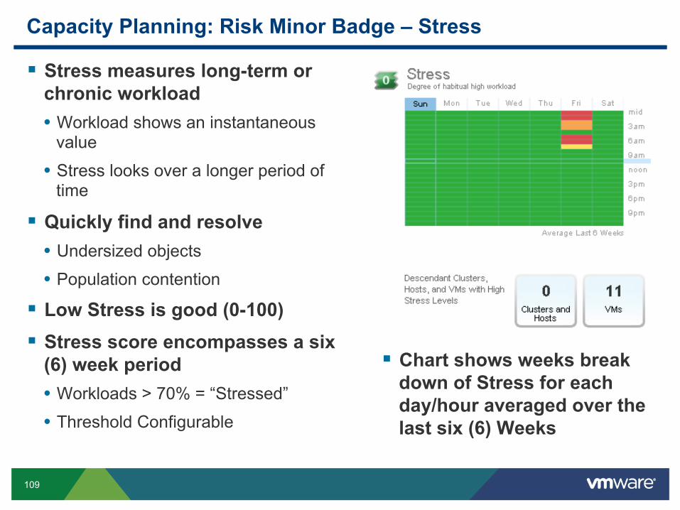
Capacity Planning: Risk Minor Badge – Stress
Stress measures long-term or chronic workload • Workload shows an instantaneous
value
• Stress looks over a longer period of time
Quickly find and resolve • Undersized objects
• Population contention
Low Stress is good (0-100) Stress score encompasses a six
(6) week period • Workloads > 70% = “Stressed”
• Threshold Configurable
Chart shows weeks break down of Stress for each day/hour averaged over the last six (6) Weeks

110
Capacity Planning: Major Badge – Efficiency
Are there optimization opportunities in my systems?
Shows you how to run a leaner datacenter
Save $$$ by better utilizing resources High Efficiency is good (100-0) Efficiency Score is calculated from its
Minor Badges • Reclaimable Waste • Density
Graph Depicts VMs by Percent • Optimal – Optimally Provisioned VMs • Waste – Over Provisioned VMs
• Stress – Under Provisioned VMs
Three Resources Considered • CPU • Memory • Disk Space
Note: VMs can appear in Stress and Waste

111
Capacity Planning: Efficiency Minor Badge – Reclaimable Waste
Measures the over-provisioning for an object
It identifies the amount of reclaimable resources • CPU • Memory
• Disk
Low Reclaimable Waste is good (0-100)
Reclaimable Waste = Reclaimable Capacity / Deployed Capacity • Score depicts the MAX of the CPU,
Memory and Disk calculation
• Disk calculation can also include old snapshots and templates
Graph shows breakdown of the Waste section of the Efficiency Badge pie chart • % Idle VMs (based on configured
settings)
• % Powered Off VMs • % Oversized VMs

112
Capacity Planning: Efficiency Minor Badge – Density
Contrasts Actual vs. Ideal Density Identify Optimal Resource
Deployment Before Contention Occurs
Greater Consolidation à $$$ High Density is good (100-0) Measures consolidation ratios:
• VMs/Host Ratios • vCPU/Physical CPU Ratios
• vMem/Physical Memory Ratios

113
vCenter Operations Management Special Offer

114
Resources

115
Resources on ESXi Migrations
VMware.com • ESXi and ESX Infocenter • vSphere 5 Upgrade Center
Documentation www.vmware.com/support/pubs/vsphere-esxi-vcenter-server-pubs.html
www.vmware.com/support/pubs/view_pubs.html
www.vmware.com/support/pubs/vcd_pubs.html
VMware VMTN Communities: ESX and ESXi

116
Questions