preparing a hutlinerpacker® / lateral connection and ... · the system manual and the operating...
TRANSCRIPT
page 1 of 39
Schwalm Robotic GmbH;; General manager: Martin Schwalm, Industriestraße 16, 36251 Bad Hersfeld-Asbach, Germany Phone +49 6621 79578-0, Fax +49 6621 79578-11, info@schwalm-robotic.de, www.schwalm-robotic.de
System manual
Preparing a HutlinerPacker® / lateral connection and setting a cap
profile or a cap liner
System manual for the S 15.2 HutlinerPacker® / lateral connection rehabilitation process,
RAL Institute GZ 961, Güteschutz Kanalbau (quality assurance in sewer construction)
page 2 of 39
Schwalm Robotic GmbH;; General manager: Martin Schwalm, Industriestraße 16, 36251 Bad Hersfeld-Asbach, Germany Phone +49 6621 79578-0, Fax +49 6621 79578-11, info@schwalm-robotic.de, www.schwalm-robotic.de
Important! Before use, please read the system manual as well as the operating instructions for the system components used and keep them in a safe place. Make sure that the system manual and the operating instructions are available at all times. SCHWALM-ROBOTIC GmbH shall not be liable for the readability of a supplied CD during the required retention period. Therefore, please file an additional hardcopy version of this system manual. If the system manual should be lost, you may request this document at www.schwalm-robotic.de
page 3 of 39
Schwalm Robotic GmbH;; General manager: Martin Schwalm, Industriestraße 16, 36251 Bad Hersfeld-Asbach, Germany Phone +49 6621 79578-0, Fax +49 6621 79578-11, info@schwalm-robotic.de, www.schwalm-robotic.de
About this system manual
This system manual forms part of the HutlinerPacker® / lateral connections and describes the safe and appropriate use and handling of the system components for sewer rehabilitation in all process stages. The system manual must always be available at the site of application of the HutlinerPacker® / lateral connection.
This system manual contains notes which are important for a safe and appropriate use of the HutlinerPacker® / lateral connections. Following these instructions helps to prevent dangers, minimise repair costs and avoid downtime. Any person in charge of working on the HutlinerPacker® / lateral connections must read and apply this system manual. For clarity purposes and due to the great number of possible situations, this system manual does not contain all detailed information and in particular cannot cover every possible case of operation or maintenance.
Service
If you desire more information or if specific issues occur which are not covered sufficiently in these operating instructions, you can request the required information. For any queries, please do not hesitate to contact:
SCHWALM-ROBOTIC GmbH Phone: +49 (0)6621 / 795780 Industriestraße 16 Fax: +49 (0)6621 / 7957811 D 36251 Bad Hersfeld/Asbach Mail: info@schwalm-robotic.de
Target group
This system manual is intended for inspectors who have successfully completed the DWA (Deutsche Vereinigung für Wasserwirtschaft, Abwasser und Abfall e.V. – German Association for Water, Wastewater and Waste) sewer inspection course or a comparable training and were additionally instructed in handling HutlinerPacker® / lateral connections by SCHWALM-ROBOTIC GmbH. HutlinerPacker® / lateral connections may only be commissioned and maintained by people who have been instructed in the appropriate use and have read and understood the content of the system manual.
Relevance
This system manual is only relevant for the HutlinerPacker® / lateral connections distributed by SCHWALM-ROBOTIC GmbH, including the required system components. This system manual does not replace practical training, which is imperative for handling the HutlinerPacker® / lateral connections. Aiming at continuous improvement, amendments are implemented at certain intervals which may not yet have been considered at the time of printing this system manual. In the case of amendments, the system manual is entirely replaced. We reserve the right to implement changes in order to develop our products.
Copyright
Copyright for this system manual remains with SCHWALM-ROBOTIC GmbH.

page 4 of 39
Schwalm Robotic GmbH;; General manager: Martin Schwalm, Industriestraße 16, 36251 Bad Hersfeld-Asbach, Germany Phone +49 6621 79578-0, Fax +49 6621 79578-11, info@schwalm-robotic.de, www.schwalm-robotic.de
Content:
About this system manual ________________________________________________________________ 3
Content: _________________________________________________________________________________ 4
Safety notes _____________________________________________________________________________ 6 Precautions when handling the HutlinerPacker® / lateral connection ____________________________________ 7 Product safety ___________________________________________________________________________________ 8 Legal disclaimer _________________________________________________________________________________ 8
System description _______________________________________________________________________ 9 Range of application _____________________________________________________________________________ 9 Intended use ____________________________________________________________________________________ 9 System components _____________________________________________________________________________ 9 Possible combinations of components _____________________________________________________________ 10
System requirements for a safe application of the Hutliner® / cap liner method ______________ 12 General course of the Hutliner® / cap liner method __________________________________________________ 12 Block diagram __________________________________________________________________________________ 13 Assembly / Commissioning _______________________________________________________________________ 13 Connections ____________________________________________________________________________________ 14 Safety devices __________________________________________________________________________________ 14 Nominal pressures – rubber hats __________________________________________________________________ 14 Nominal pressures - HutlinerPacker® / lateral connections ___________________________________________ 15
Processing components for forming the Hutliner® / cap liners _____________________________ 15 Support components ____________________________________________________________________________ 15 Reaction components – 2-unit resin system ________________________________________________________ 16 Mixing ratio ____________________________________________________________________________________ 16 Quantities ______________________________________________________________________________________ 16 Required resin system quantities and mat lengths for HutlinerPacker® / lateral connections: ___________ 17 Required resin system quantities for felt hats: ____________________________________________________ 17
Technological dwell times ________________________________________________________________________ 18 Cold hardening _______________________________________________________________________________ 18 Heat ________________________________________________________________________________________ 18 Storage _____________________________________________________________________________________ 18 Reaction times dependent on temperature and used unit 1: _______________________________________ 18 Safety information for handling reaction resins ___________________________________________________ 18
System specifications and standard requirements _________________________________________ 19 HutlinerPacker® / lateral connection type dependent on the nominal width _____________________________ 19 Ambient conditions ______________________________________________________________________________ 19 Temperature, humidity ___________________________________________________________________________ 19 Compressed air requirements ____________________________________________________________________ 19 Water retention in the rehab sewer ________________________________________________________________ 19
Implementation of the Hutliner® / cap liner rehab __________________________________________ 20 Devices, equipment (minimum equipment) _________________________________________________________ 20 Preparatory measures ___________________________________________________________________________ 20 Checking and donning the PPE (personal protective equipment) ______________________________________ 21 Preparing the gluing spot ________________________________________________________________________ 21 Cleaning the gluing spot _________________________________________________________________________ 22 Selecting the rubber hat _________________________________________________________________________ 22 Rubber hat sealing ______________________________________________________________________________ 23 Fixing the rubber hat ____________________________________________________________________________ 23

page 5 of 39
Schwalm Robotic GmbH;; General manager: Martin Schwalm, Industriestraße 16, 36251 Bad Hersfeld-Asbach, Germany Phone +49 6621 79578-0, Fax +49 6621 79578-11, info@schwalm-robotic.de, www.schwalm-robotic.de
Attaching the PE bag ____________________________________________________________________________ 24 Wrapping into PE wrapping film ___________________________________________________________________ 24 PE wrapping foil around rubber hat ________________________________________________________________ 25 Trimming the rubber hats ________________________________________________________________________ 25 Preparing the fibreglass mat ______________________________________________________________________ 26 Preparing the resin system _______________________________________________________________________ 28 Resin treatment of the E-CR fibreglass mat ________________________________________________________ 29 Resin treatment of the felt hat ____________________________________________________________________ 30 Attaching the felt hat ____________________________________________________________________________ 31 Applying the fibreglass mat _______________________________________________________________________ 32 Connect air supplies ____________________________________________________________________________ 33 Parking the milling tool __________________________________________________________________________ 33 Lowering the HutlinerPacker® / lateral connections __________________________________________________ 34 Coupling the milling tool _________________________________________________________________________ 34 Transporting the packer _________________________________________________________________________ 35 Threading the felt hat ____________________________________________________________________________ 35 Inflating the HutlinerPacker® / lateral connection ____________________________________________________ 36 Lowering the HutlinerPacker® / lateral connection ___________________________________________________ 37 Acceptance ____________________________________________________________________________________ 37
Control and maintenance ________________________________________________________________ 38
Accessory list ___________________________________________________________________________ 39
page 6 of 39
Schwalm Robotic GmbH;; General manager: Martin Schwalm, Industriestraße 16, 36251 Bad Hersfeld-Asbach, Germany Phone +49 6621 79578-0, Fax +49 6621 79578-11, info@schwalm-robotic.de, www.schwalm-robotic.de
Safety notes
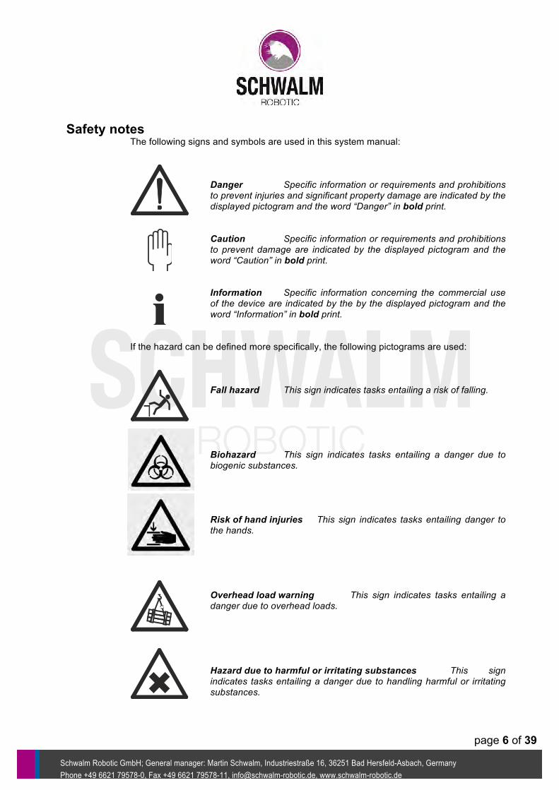
The following signs and symbols are used in this system manual:
Danger Specific information or requirements and prohibitions to prevent injuries and significant property damage are indicated by the displayed pictogram and the word “Danger” in bold print. Caution Specific information or requirements and prohibitions to prevent damage are indicated by the displayed pictogram and the word “Caution” in bold print. Information Specific information concerning the commercial use of the device are indicated by the by the displayed pictogram and the word “Information” in bold print.
If the hazard can be defined more specifically, the following pictograms are used: Fall hazard This sign indicates tasks entailing a risk of falling. Biohazard This sign indicates tasks entailing a danger due to biogenic substances. Risk of hand injuries This sign indicates tasks entailing danger to the hands. Overhead load warning This sign indicates tasks entailing a danger due to overhead loads. Hazard due to harmful or irritating substances This sign indicates tasks entailing a danger due to handling harmful or irritating substances.

page 7 of 39
Schwalm Robotic GmbH;; General manager: Martin Schwalm, Industriestraße 16, 36251 Bad Hersfeld-Asbach, Germany Phone +49 6621 79578-0, Fax +49 6621 79578-11, info@schwalm-robotic.de, www.schwalm-robotic.de
Precautions when handling the HutlinerPacker® / lateral connection There is a falling hazard when handling the HutlinerPacker® / lateral connection at an open sewer. There is a biohazard when working in the sewage area and with equipment that is contaminated with biogenic substances after use. There is a hand injury hazard when manipulating HutlinerPacker® / lateral connections into the sewer and when assembling the connection. There is an overhead load hazard when handling HutlinerPacker® / lateral connections with a hoist. Hazards due to harmful or irritating substances must be considered when handling the required resins and components and for the final cleaning of the equipment.
There is a danger due to damage resulting from air chamber rupture when damaged air chambers are used and when the maximum pressures in the air chambers are exceeded. Danger The information on maximum pressure for the HutlinerPacker® / lateral connections only relates to the working state on site in the sewer. Outside the pipelines, the HutlinerPacker® / lateral connections may only be filled up to 0.2 bar for visual inspection. Danger The HutlinerPacker® / lateral connections and their components may only be operated consistent with their intended use, in a safety- and risk conscious manner, in accordance with the operating instructions in the HutlinerPacker® / lateral connection system when they are in a technically sound state, undamaged and working without malfunction. Even during intended use of the HutlinerPacker® / lateral connections, faulty operation by the machinists, misconduct of building site personnel, a fault or a control breakdown may lead to hazardous situations.

page 8 of 39
Schwalm Robotic GmbH;; General manager: Martin Schwalm, Industriestraße 16, 36251 Bad Hersfeld-Asbach, Germany Phone +49 6621 79578-0, Fax +49 6621 79578-11, info@schwalm-robotic.de, www.schwalm-robotic.de
Product safety The HutlinerPacker® / lateral connections have been constructed according to the state of the art technology and recognised safety-related rules. However, use of the HutlinerPacker® / lateral connections may lead to dangers to life for users or third parties and / or to damage to the HutlinerPacker® / lateral connections and other property.
Legal disclaimer
Information We expressly note that SCHWALM-ROBOTIC GmbH shall not be liable for damage resulting from faulty or negligent operation, maintenance or repair or due to unintended use. This also applies for changes, extensions and conversions of the HutlinerPacker® / lateral connections which can affect safety. In such cases, the factory guarantee is no longer valid.
page 9 of 39
Schwalm Robotic GmbH;; General manager: Martin Schwalm, Industriestraße 16, 36251 Bad Hersfeld-Asbach, Germany Phone +49 6621 79578-0, Fax +49 6621 79578-11, info@schwalm-robotic.de, www.schwalm-robotic.de
System description Range of application
The HutlinerPacker® / lateral connections allows fitting cap profiles or Hutliner® / lateral connections in a nominal width area of DN 100 to DN 800 in the main pipe and a nominal width area of DN 100 to DN 250 at an angle of 30° to 90° in the connection pipe. The method is suitable for rehabilitation of pipelines and concrete shaped parts, stoneware, fibre cement, cast iron, and reinforced and non-reinforced plastics. Limits of application: The application of the HutlinerPacker® / lateral connection is limited by certain failure modes in the non-rehabilitated main sewer as well as by unusual outlet angles.
Intended use The HutlinerPacker® / lateral connections are devices for installing cap profiles and Hutliner® / cap liners for form-fit integration of sewage hook-ups into other sewage channels. The major case of application is the tethering of a connecting pipeline to a sewer rehabilitated via relining. The cap profile or Hutliner® / cap liner process is also suitable for repairing junctions using the original pipeline construction. With the HutlinerPacker® / lateral connection, a cap profile is inserted into the prepared branch or junction of the confluent sewer. For this purpose, a resin-impregnated cap profile made of synthetic fibre felt is placed onto the HutlinerPacker® / lateral connection’s rubber hat and placed and fastened on the application spot by a robot, monitored by TV. The HutlinerPacker® / lateral connection is expanded using compressed air and the cap profile is pressed against the tube wall of the main line where it hardens at ambient temperature. After application, the cap profile collar should be connected form-fit with the inner wall of the main sewer, and the hose should be connected form-fit with the connecting line. Intended use also includes complying with all information in this system manual.
System components The HutlinerPacker® / lateral connections are provided with the following system components:
• Packers with 2 separate pressure chambers • Connection hoses for compressed air • Customary pressure reducer / regulator • 2 resin system components • Cap profile and fibreglass mat, if necessary • Robot-specific support plate • Talpa milling robot
The conditions required for an operation as defined by the system target include: • System components in a combination of hardware system components
geared towards target attainment • Availability of adjustable compressed air, max. 2.5 bar • Availability of other media for supplying the milling and rehabilitation
robot • Manpower qualified for handling the system
page 10 of 39
Schwalm Robotic GmbH;; General manager: Martin Schwalm, Industriestraße 16, 36251 Bad Hersfeld-Asbach, Germany Phone +49 6621 79578-0, Fax +49 6621 79578-11, info@schwalm-robotic.de, www.schwalm-robotic.de
Possible combinations of components There are HutlinerPacker® (HLP) / lateral connections available for four major diameters: Table 1
HutlinerPacker® (Nominal width) Design HutlinerFlexpacker® DN 100 without flow passage HutlinerFlexpacker® DN 125 without flow passage HutlinerFlexpacker® DN 150 without flow passage HutlinerFlexpacker® DN 180 without flow passage
HutlinerFlexpacker® DN 200 without flow passage without flow passage HutlinerFlexpacker® DN 200 with flow passage with flow passage
HutlinerPacker® DN 250-300 with flow passage HutlinerPacker® DN 300-400 with flow passage HutlinerPacker® DN 400-500 with flow passage HutlinerPacker® DN 400-600 with flow passage HutlinerPacker® DN 500-700 with flow passage HutlinerPacker® DN 600-800 with flow passage
Multipurpose packers are adapted to the several nominal widths by an implemented chassis adjusting system on the HutlinerPacker® / lateral connection. There are rubber hats for the HutlinerPacker® / lateral connections available in the following sizes: Table 2
Rubber hat Connection diameter Size 1 90 – 125 mm Size 2 >125 – 160 mm
Size 2, long >125 – 160 mm Size 3 >160 – 250 mm Size 4 90 – 150 mm (HLP 150) Size 5 90 - 125 mm (HLP 100 and 125)
Cap profiles are available for the following diameters and angles:
• DN 100, DN 125, DN 150, DN 200, DN 250 • Angles 45° and 90°, respectively
Resin system for impregnation of the cap profiles and, if applicable, the fibreglass, consisting of 2 units in a standard bottle system:
• Resin and catalyser: Unit 1 (components A + C) • Curing agent: Unit 2 (component B)
Separating agent for separating the reusable hardware components of the HutlinerPacker® / lateral connection system of the rehabilitation components remaining in situ:
• Separating agent (non-stick agent) • PE film (rolls, bags)
Fixing agent for temporary mechanical fixing of the rubber hat and the impregnated cap profiles and / or on the Hutliner® / cap liners on the HutlinerPacker® / lateral connections:

page 11 of 39
Schwalm Robotic GmbH;; General manager: Martin Schwalm, Industriestraße 16, 36251 Bad Hersfeld-Asbach, Germany Phone +49 6621 79578-0, Fax +49 6621 79578-11, info@schwalm-robotic.de, www.schwalm-robotic.de
• Rubber bands DN50, DN 80, DN 100, DN 200, DN 260 • Crepe tape
Robots for positioning the standard HutlinerPacker® / lateral connections at the place of application:
• Robots with engaging adapter for retaining plate • Retaining plate for form- and force-fit engaging of the HutlinerPacker® / lateral
connections
Caution The individual hardware components may be systemically combined with each other within the given limits, according to the target of application.
page 12 of 39
Schwalm Robotic GmbH;; General manager: Martin Schwalm, Industriestraße 16, 36251 Bad Hersfeld-Asbach, Germany Phone +49 6621 79578-0, Fax +49 6621 79578-11, info@schwalm-robotic.de, www.schwalm-robotic.de
System requirements for a safe application of the Hutliner® / cap liner method
In general, the following system components are applied in situ:
• HutlinerPacker® / lateral connections of the appropriate size • Cap profile of the appropriate size • E-CR fibreglass mat of the appropriate size • Felt hat (polyester fibre felt) • 2-unit resin system of the appropriate quantity • Robot-specific retaining plate • Milling robot with an appropriate control system • Air compressor • Standard pressure reducer / regulator • Connecting hoses for air • Various auxiliary materials and safety equipment
General course of the Hutliner® / cap liner method
Fitting the cap profiles and or Hutliner® / cap liners is geared to the following general requirements: - First of all, the connection area is prepared mechanically for the fitting of the cap profile or Hutliner® / cap liner. When tethering the connection lines to a main sewer, the area the cap profile or Hutliner® / cap liner should abut to is mechanically cleaned. The milling residues are removed by high-pressure cleaning. - The HutlinerPacker® / lateral connection is selected and prepared for application according to the nominal width of the main line. The rubber hat is selected and prepared for application according to the connection line to be tethered. - The cap profile or Hutliner® / cap liner is selected according to the failure mode and to the nominal width of the connection sewer and the main sewer and is impregnated with the resin. The impregnation is applied manually. The pot lives only allow a limited application period. - A robot carries the HutlinerPacker® / lateral connection with the cap profile or Hutliner® / cap liner to the faulty spot where it inserts the cap profile into the connection line. Due to the controlled filling of the pressure chambers with compressed air, the hose of the cap profile is pressed against the connection line wall, and the collar – and, if applicable, the fibreglass laminate – is pressed against the main line wall. - The process is controlled remotely by the technician inside the vehicle. The process is monitored by the robot camera in the main tube. - The cap profile or Hutliner® / cap liner cures at ambient temperature and under compressive load of the HutlinerPacker® / lateral connection. - Once the cap profile has cured, the HutlinerPacker® / lateral connection pressure chambers are depressurized and the HutlinerPacker® / lateral connections are manually removed from the operating site. The next steps are the quality control and, if applicable, post-treatments.
page 13 of 39
Schwalm Robotic GmbH;; General manager: Martin Schwalm, Industriestraße 16, 36251 Bad Hersfeld-Asbach, Germany Phone +49 6621 79578-0, Fax +49 6621 79578-11, info@schwalm-robotic.de, www.schwalm-robotic.de
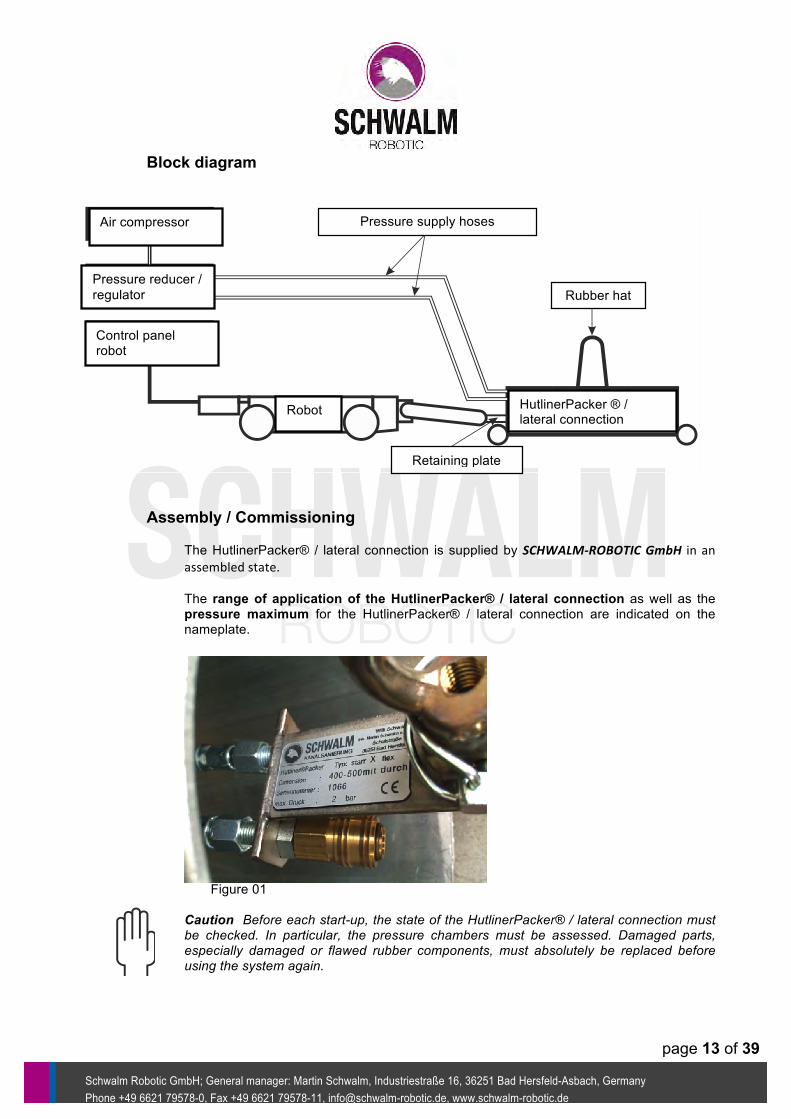
Block diagram
Assembly / Commissioning
The HutlinerPacker® / lateral connection is supplied by SCHWALM-‐ROBOTIC GmbH in an assembled state. The range of application of the HutlinerPacker® / lateral connection as well as the pressure maximum for the HutlinerPacker® / lateral connection are indicated on the nameplate. Figure 01 Caution Before each start-up, the state of the HutlinerPacker® / lateral connection must be checked. In particular, the pressure chambers must be assessed. Damaged parts, especially damaged or flawed rubber components, must absolutely be replaced before using the system again.
Air compressor
Pressure reducer / regulator
Control panel robot
Robot HutlinerPacker ® / lateral connection
Rubber hat
Pressure supply hoses
Retaining plate
page 14 of 39
Schwalm Robotic GmbH;; General manager: Martin Schwalm, Industriestraße 16, 36251 Bad Hersfeld-Asbach, Germany Phone +49 6621 79578-0, Fax +49 6621 79578-11, info@schwalm-robotic.de, www.schwalm-robotic.de
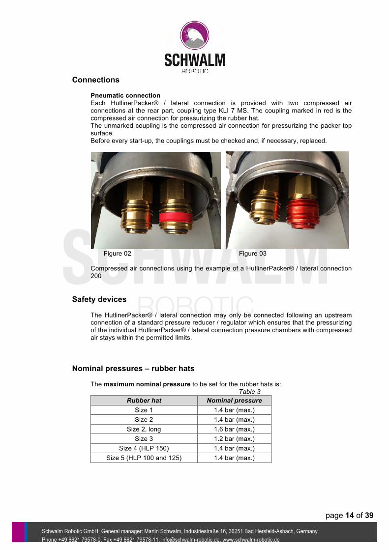
Connections
Pneumatic connection Each HutlinerPacker® / lateral connection is provided with two compressed air connections at the rear part, coupling type KLI 7 MS. The coupling marked in red is the compressed air connection for pressurizing the rubber hat. The unmarked coupling is the compressed air connection for pressurizing the packer top surface. Before every start-up, the couplings must be checked and, if necessary, replaced. Figure 02 Figure 03 Compressed air connections using the example of a HutlinerPacker® / lateral connection 200
Safety devices
The HutlinerPacker® / lateral connection may only be connected following an upstream connection of a standard pressure reducer / regulator which ensures that the pressurizing of the individual HutlinerPacker® / lateral connection pressure chambers with compressed air stays within the permitted limits.
Nominal pressures – rubber hats
The maximum nominal pressure to be set for the rubber hats is: Table 3
Rubber hat Nominal pressure Size 1 1.4 bar (max.) Size 2 1.4 bar (max.)
Size 2, long 1.6 bar (max.) Size 3 1.2 bar (max.)
Size 4 (HLP 150) 1.4 bar (max.) Size 5 (HLP 100 and 125) 1.4 bar (max.)
page 15 of 39
Schwalm Robotic GmbH;; General manager: Martin Schwalm, Industriestraße 16, 36251 Bad Hersfeld-Asbach, Germany Phone +49 6621 79578-0, Fax +49 6621 79578-11, info@schwalm-robotic.de, www.schwalm-robotic.de
Nominal pressures - HutlinerPacker® / lateral connections
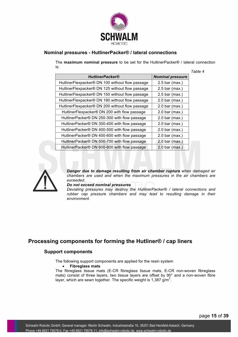
The maximum nominal pressure to be set for the HutlinerPacker® / lateral connection is: Table 4
HutlinerPacker® Nominal pressure HutlinerFlexpacker® DN 100 without flow passage 2.5 bar (max.) HutlinerFlexpacker® DN 125 without flow passage 2.5 bar (max.) HutlinerFlexpacker® DN 150 without flow passage 2.5 bar (max.) HutlinerFlexpacker® DN 180 without flow passage 2.0 bar (max.) HutlinerFlexpacker® DN 200 without flow passage 2.0 bar (max.) HutlinerFlexpacker® DN 200 with flow passage 2.0 bar (max.) HutlinerPacker® DN 250-300 with flow passage 2.0 bar (max.) HutlinerPacker® DN 300-400 with flow passage 2.0 bar (max.) HutlinerPacker® DN 400-500 with flow passage 2.0 bar (max.) HutlinerPacker® DN 400-600 with flow passage 2.0 bar (max.) HutlinerPacker® DN 500-700 with flow passage 2.0 bar (max.) HutlinerPacker® DN 600-800 with flow passage 2.0 bar (max.)
Danger due to damage resulting from air chamber rupture when damaged air chambers are used and when the maximum pressures in the air chambers are exceeded. Do not exceed nominal pressures Deviating pressures may destroy the HutlinerPacker® / lateral connections and rubber cap pressure chambers and may lead to resulting damage in their environment.
Processing components for forming the Hutliner® / cap liners
Support components
The following support components are applied for the resin system • Fibreglass mats
The fibreglass tissue mats (E-CR fibreglass tissue mats, E-CR non-woven fibreglass mats) consist of three layers, two tissue layers are offset by 90° and a non-woven fibre layer, which are sewn together. The specific weight is 1,387 g/m2.
page 16 of 39
Schwalm Robotic GmbH;; General manager: Martin Schwalm, Industriestraße 16, 36251 Bad Hersfeld-Asbach, Germany Phone +49 6621 79578-0, Fax +49 6621 79578-11, info@schwalm-robotic.de, www.schwalm-robotic.de
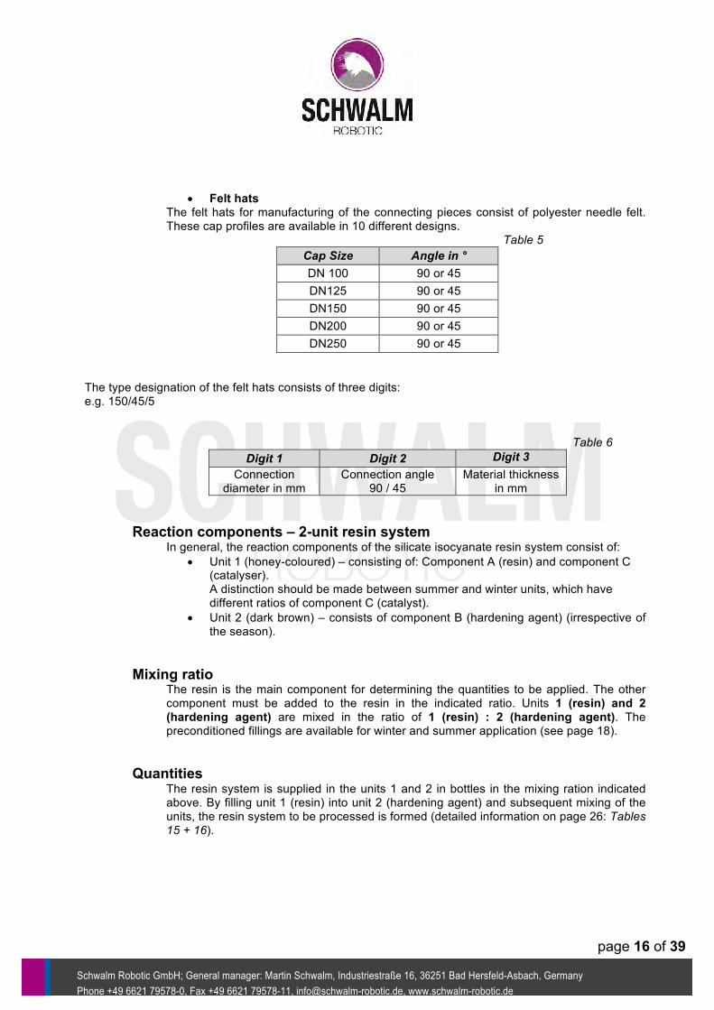
• Felt hats The felt hats for manufacturing of the connecting pieces consist of polyester needle felt. These cap profiles are available in 10 different designs.
Table 5 Cap Size Angle in ° DN 100 90 or 45 DN125 90 or 45 DN150 90 or 45 DN200 90 or 45 DN250 90 or 45
The type designation of the felt hats consists of three digits: e.g. 150/45/5
Table 6 Digit 1 Digit 2 Digit 3
Connection diameter in mm
Connection angle 90 / 45
Material thickness in mm
Reaction components – 2-unit resin system In general, the reaction components of the silicate isocyanate resin system consist of:
• Unit 1 (honey-coloured) – consisting of: Component A (resin) and component C (catalyser). A distinction should be made between summer and winter units, which have different ratios of component C (catalyst).
• Unit 2 (dark brown) – consists of component B (hardening agent) (irrespective of the season).
Mixing ratio The resin is the main component for determining the quantities to be applied. The other component must be added to the resin in the indicated ratio. Units 1 (resin) and 2 (hardening agent) are mixed in the ratio of 1 (resin) : 2 (hardening agent). The preconditioned fillings are available for winter and summer application (see page 18).
Quantities
The resin system is supplied in the units 1 and 2 in bottles in the mixing ration indicated above. By filling unit 1 (resin) into unit 2 (hardening agent) and subsequent mixing of the units, the resin system to be processed is formed (detailed information on page 26: Tables 15 + 16).

page 17 of 39
Schwalm Robotic GmbH;; General manager: Martin Schwalm, Industriestraße 16, 36251 Bad Hersfeld-Asbach, Germany Phone +49 6621 79578-0, Fax +49 6621 79578-11, info@schwalm-robotic.de, www.schwalm-robotic.de
Required resin system quantities and mat lengths for HutlinerPacker® / lateral connections:
Table 7
Diameter Length for 127 cm mat width
Total resin quantity Unit 1 (resin) Unit 2 (hardening agent)
DN 100 36 cm 0.75 l 0.25 l 0.5 l DN 125 45 cm 1.0 l 0.335 l 0.665 l DN 150 56 cm 1.0 l 0.335 l 0.665 l DN 200 70 cm 1.0 l 0.335 l 0.665 l DN 250 85 cm 1.5 l 0.5 l 1.0 l DN 300 100 cm 2.0 l 0.67 l 1.33 l DN 350 115 cm 2.0 l 0.67 l 1.33 l DN 400 135 cm 2.5 l 0.835 l 1.665 l DN 500 170 cm 3.0 l 1.005 l 1.995 l DN 600 200 cm 4.5 l 1.505 l 2.995 l DN 700 250 cm 5.0 l 1.675 l 3.325 l DN 800 310 cm 6.0 l 2.01 l 3.99 l
Table 8
Uniform bottles pre-assembled for the cap profiles and
Hutliner® / cap liners
Pre-assembled uniform bottle unit 2 0.5 l Pre-assembled uniform bottle unit 2 0.665 l
Pre-assembled uniform bottle unit 1 summer 0.250 l Pre-assembled uniform bottle unit 1 winter 0.250 l Pre-assembled uniform bottle unit 1 summer 0.335 l Pre-assembled uniform bottle unit 1 winter 0.335 l
Required resin system quantities for felt hats: Table 9
Felt hat Total resin quantity Unit 1 (resin) Unit 2 (hardening agent)
DN 100 0.75 l 0.25 l 0.5 l DN 125 1.0 l 0.335 l 0.665 l DN 150 1.0 l 0.335 l 0.665 l
DN 150, long 1.5 l 0.5 l 1.0 l DN 200 1.5 l 0.5 l 1.0 l DN 250 1.5 l 0.5 l 1.0 l
The quantity indications are benchmarks. The quantity can differ according to size and failure mode type!
Information The conversion of the required resin system quantities in a standardized amount of the units 1 and 2 in bottles can be found on page 26: tables 15 + 16 in the resin preparation section.

page 18 of 39
Schwalm Robotic GmbH;; General manager: Martin Schwalm, Industriestraße 16, 36251 Bad Hersfeld-Asbach, Germany Phone +49 6621 79578-0, Fax +49 6621 79578-11, info@schwalm-robotic.de, www.schwalm-robotic.de
Technological dwell times
The dwell times which depend on the temperature and technological conditions must absolutely be adhered to. The dwell times required for the curing of the mixed resin system are distinguished into:
Pot life: Processability time (during which the resin system can be spread) Placing time: Time for manipulating the liners to and at the place of application Deshelling time: Time for dwelling of the HutlinerPacker® / lateral connection at the
place of application under pressure
Cold hardening The resin is cured in a cold-hardening manner, i.e. without heat input from the outside, at ambient temperature. The ambient temperature must be at least 8°C.
Heat The reaction time of the resin system depends on the temperature and determines the time periods available for processing. Depending on the resin quantity applied, the resin reaction leads to process heat which also affects the reaction process;; the reaction time is reduced.
Storage Reactive resins should be stored in a dry place at a temperature of at least 10°C.
Reaction times dependent on temperature and used unit 1:
Table 10 Temperature Times Unit 1
Summer Winter
10° C Pot life - 12 min.
Placing time - 25 min. Deshelling time - 90 min.
15° C Pot life - 10 min.
Placing time - 20 min. Deshelling time - 60 min.
20° C Pot life 15 min. 8 min.
Placing time 25 min. 15 min. Deshelling time 90 min. 50 min.
25° C Pot life 15 min. -
Placing time 20 min. - Deshelling time 60 min. -
30° C Pot life 8 min. -
Placing time 15 min. - Deshelling time 50 min. -
This table is for orientation purposes;; real values can differ.
Safety information for handling reaction resins
The resin system is subject to the hazard designation: Xn (harmful), Xi (irritating). The specific danger information, information about first aid measures and disposal can be found in the current safety data sheets for this product which are to be requested from the supplier.

page 19 of 39
Schwalm Robotic GmbH;; General manager: Martin Schwalm, Industriestraße 16, 36251 Bad Hersfeld-Asbach, Germany Phone +49 6621 79578-0, Fax +49 6621 79578-11, info@schwalm-robotic.de, www.schwalm-robotic.de
System specifications and standard requirements HutlinerPacker® / lateral connection type dependent on the nominal width Table 11
HutlinerPacker® (nominal width) HutlinerFlexpacker® DN 100 without flow passage HutlinerFlexpacker® DN 125 without flow passage HutlinerFlexpacker® DN 150 without flow passage HutlinerFlexpacker® DN 180 without flow passage
HutlinerFlexpacker® DN 200 without and with flow passage HutlinerPacker® DN 250-300 with flow passage HutlinerPacker® DN 300-400 with flow passage HutlinerPacker® DN 400-500 with flow passage HutlinerPacker® DN 400-600 with flow passage HutlinerPacker® DN 500-700 with flow passage HutlinerPacker® DN 600-800 with flow passage
Ambient conditions
Caution Differing sewage conditions may destroy the HutlinerPacker® / lateral connection. The HutlinerPacker® / lateral connections are designed for the application in the municipal wastewater sector with a pH value of 3 – 9. When applied in the industrial sewage sector, the chemical composition of the wastewater must be analysed beforehand.
Temperature, humidity
Application of the HutlinerPacker® / lateral connection is restricted to frost-‐free space in the sewage area. The HutlinerPacker® / lateral connections are designed to be applied in a wet environment.
Compressed air requirements
The compressed air to be applied should either be supplied from bottles or from air compressors. The air should be largely dry and free of oil. There is a danger due to damage resulting from air chamber rupture when damaged air chambers are used and when the maximum pressures in the air chambers are exceeded.
Water retention in the rehab sewer
Before starting the rehabilitation, the water ratios within the sewer must be verified for the time of work in the sewer. It must be ensured that
• the lines concerned do not conduct wastewater or • a HutlinerPacker® / lateral connection permitting flow has been selected.
Otherwise, the respective blocking measures in the sewer must be selected;; e.g. setting blocking bladders or installing bypasses.

page 20 of 39
Schwalm Robotic GmbH;; General manager: Martin Schwalm, Industriestraße 16, 36251 Bad Hersfeld-Asbach, Germany Phone +49 6621 79578-0, Fax +49 6621 79578-11, info@schwalm-robotic.de, www.schwalm-robotic.de
Implementation of the Hutliner® / cap liner rehab
Devices, equipment (minimum equipment)
For setting the Hutliner® / cap liner or cap profiles, the following equipment is necessary: - Devices for exploring and preparing the operation site - Devices for cleaning the application area (sewer cleaning) - Water retention facilities - Devices for channel inspection - Devices for setting the Hutliner® / cap liners or cap profiles - Personal protective equipment (PPE) - Gas detector - Tripod (personal security device) - Safety and rescue harness - HutlinerPacker® / lateral connections and accessories depending on the nominal width - Bottles with resin components - Weather protected impregnation workplace - Construction sheeting - E-CR fibreglass mat and felt hats for the nominal width to be rehabilitated - Separating agents (non-stick agent, PE film) - Rehabilitation robot with control unit and monitoring screen - Compressed air hoses - Blocking bladders - Compressed air supply with pressure regulating device - Water supply - Power supply - Container for residues - Temperature meter - Tools for handling the process components
Preparatory measures If the rehabilitation site is located within the public traffic space, appropriate measures for traffic security and management must be taken. When preparing the actions in situ, the conditions for wastewater must be suitably provided for the rehab. The main connections should be put out of operation, if possible. In the sewer to be integrated, appropriate measures for water retention should be taken. The affected line section and the service line locations must be calibrated and reported. It must be verified that the sewers are gas-free. The ambient temperature of the rehabilitation site must be measured and a corresponding estimation of the temperature limits and processing times must be made. The required PPE and the corresponding securing and rescuing technique for the staff must be provided in situ.
page 21 of 39
Schwalm Robotic GmbH;; General manager: Martin Schwalm, Industriestraße 16, 36251 Bad Hersfeld-Asbach, Germany Phone +49 6621 79578-0, Fax +49 6621 79578-11, info@schwalm-robotic.de, www.schwalm-robotic.de
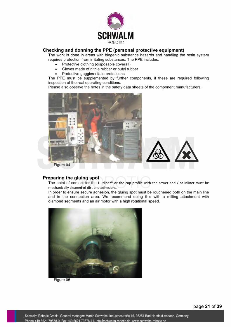
Checking and donning the PPE (personal protective equipment) The work is done in areas with biogenic substance hazards and handling the resin system requires protection from irritating substances. The PPE includes:
• Protective clothing (disposable coverall) • Gloves made of nitrile rubber or butyl rubber • Protective goggles / face protections
The PPE must be supplemented by further components, if these are required following inspection of the real operating conditions. Please also observe the notes in the safety data sheets of the component manufacturers.
Figure 04
Preparing the gluing spot The point of contact for the Hutliner® or the cap profile with the sewer and / or inliner must be mechanically cleaned of dirt and adhesions. In order to ensure secure adhesion, the gluing spot must be roughened both on the main line and in the connection area. We recommend doing this with a milling attachment with diamond segments and an air motor with a high rotational speed.
Figure 05
page 22 of 39
Schwalm Robotic GmbH;; General manager: Martin Schwalm, Industriestraße 16, 36251 Bad Hersfeld-Asbach, Germany Phone +49 6621 79578-0, Fax +49 6621 79578-11, info@schwalm-robotic.de, www.schwalm-robotic.de
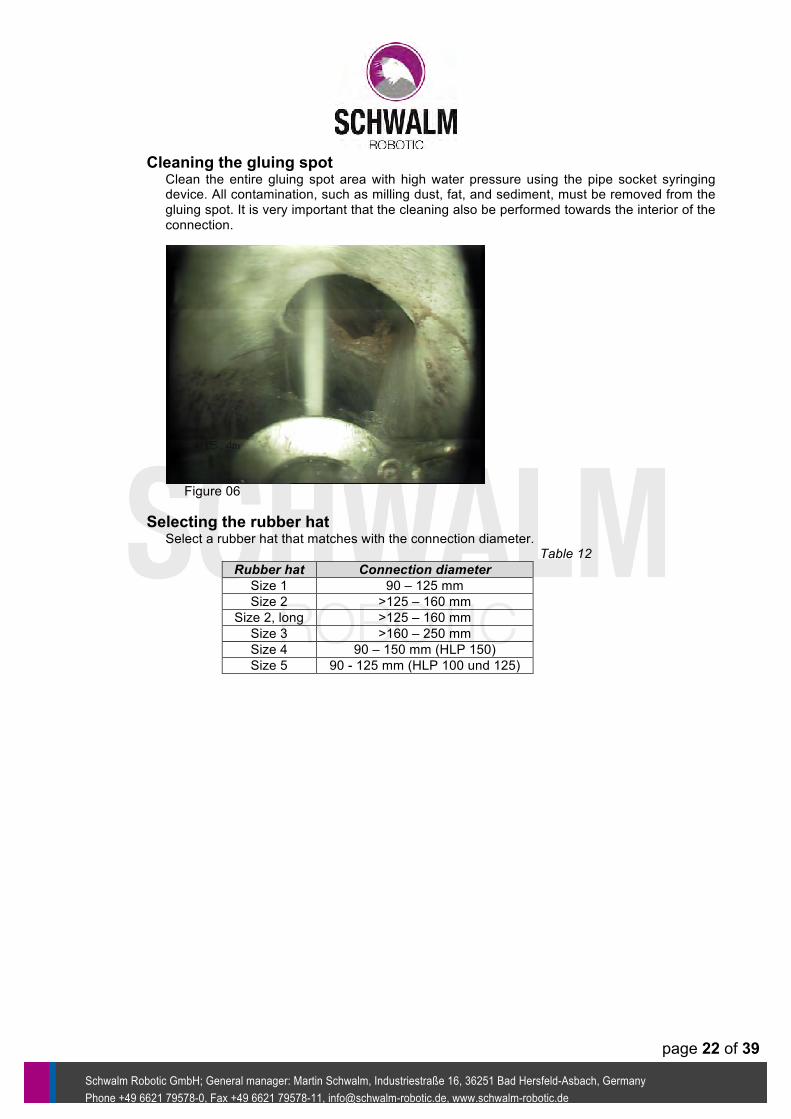
Cleaning the gluing spot Clean the entire gluing spot area with high water pressure using the pipe socket syringing device. All contamination, such as milling dust, fat, and sediment, must be removed from the gluing spot. It is very important that the cleaning also be performed towards the interior of the connection.
Figure 06
Selecting the rubber hat Select a rubber hat that matches with the connection diameter. Table 12
Rubber hat Connection diameter Size 1 90 – 125 mm Size 2 >125 – 160 mm
Size 2, long >125 – 160 mm Size 3 >160 – 250 mm Size 4 90 – 150 mm (HLP 150) Size 5 90 - 125 mm (HLP 100 und 125)
page 23 of 39
Schwalm Robotic GmbH;; General manager: Martin Schwalm, Industriestraße 16, 36251 Bad Hersfeld-Asbach, Germany Phone +49 6621 79578-0, Fax +49 6621 79578-11, info@schwalm-robotic.de, www.schwalm-robotic.de
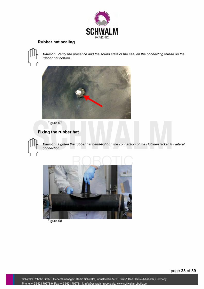
Rubber hat sealing Caution Verify the presence and the sound state of the seal on the connecting thread on the rubber hat bottom.
Figure 07
Fixing the rubber hat Caution Tighten the rubber hat hand-tight on the connection of the HutlinerPacker ® / lateral connection.
Figure 08
page 24 of 39
Schwalm Robotic GmbH;; General manager: Martin Schwalm, Industriestraße 16, 36251 Bad Hersfeld-Asbach, Germany Phone +49 6621 79578-0, Fax +49 6621 79578-11, info@schwalm-robotic.de, www.schwalm-robotic.de
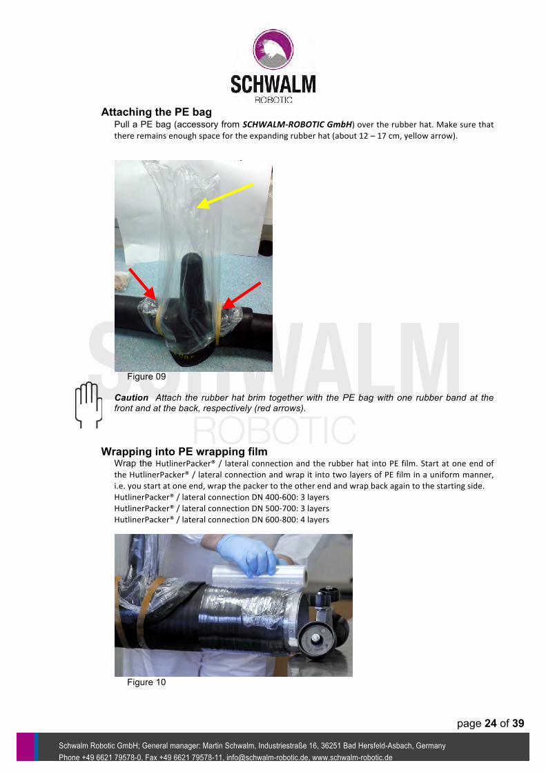
Attaching the PE bag Pull a PE bag (accessory from SCHWALM-‐ROBOTIC GmbH) over the rubber hat. Make sure that there remains enough space for the expanding rubber hat (about 12 – 17 cm, yellow arrow).
Figure 09
Caution Attach the rubber hat brim together with the PE bag with one rubber band at the front and at the back, respectively (red arrows).
Wrapping into PE wrapping film Wrap the HutlinerPacker® / lateral connection and the rubber hat into PE film. Start at one end of the HutlinerPacker® / lateral connection and wrap it into two layers of PE film in a uniform manner, i.e. you start at one end, wrap the packer to the other end and wrap back again to the starting side. HutlinerPacker® / lateral connection DN 400-‐600: 3 layers HutlinerPacker® / lateral connection DN 500-‐700: 3 layers HutlinerPacker® / lateral connection DN 600-‐800: 4 layers
Figure 10
page 25 of 39
Schwalm Robotic GmbH;; General manager: Martin Schwalm, Industriestraße 16, 36251 Bad Hersfeld-Asbach, Germany Phone +49 6621 79578-0, Fax +49 6621 79578-11, info@schwalm-robotic.de, www.schwalm-robotic.de
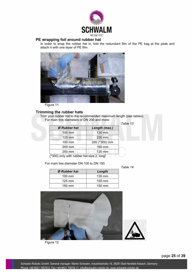
PE wrapping foil around rubber hat In order to wrap the rubber hat in, fold the redundant film of the PE bag at the peak and attach it with one layer of PE film.
Figure 11
Trimming the rubber hats Trim your rubber hat to the recommended maximum length (see tables). For main line diameters of DN 200 and more: Table 13
Ø Rubber hat Length (max.) 100 mm 130 mm 125 mm 230 mm 150 mm 200 (*300) mm 200 mm 160 mm 250 mm 120 mm
(*300) only with rubber hat size 2, long!
For main line diameter DN 100 to DN 150 Table 14
Ø Rubber hat Length 100 mm 130 mm 125 mm 150 mm 150 mm 150 mm
Figure 12
page 26 of 39
Schwalm Robotic GmbH;; General manager: Martin Schwalm, Industriestraße 16, 36251 Bad Hersfeld-Asbach, Germany Phone +49 6621 79578-0, Fax +49 6621 79578-11, info@schwalm-robotic.de, www.schwalm-robotic.de
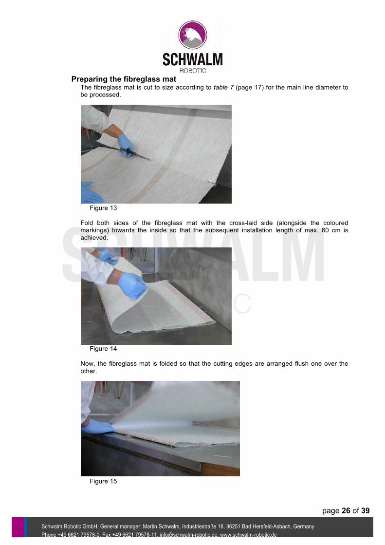
Preparing the fibreglass mat The fibreglass mat is cut to size according to table 7 (page 17) for the main line diameter to be processed.
Figure 13
Fold both sides of the fibreglass mat with the cross-laid side (alongside the coloured markings) towards the inside so that the subsequent installation length of max. 60 cm is achieved.
Figure 14
Now, the fibreglass mat is folded so that the cutting edges are arranged flush one over the other.
Figure 15

page 27 of 39
Schwalm Robotic GmbH;; General manager: Martin Schwalm, Industriestraße 16, 36251 Bad Hersfeld-Asbach, Germany Phone +49 6621 79578-0, Fax +49 6621 79578-11, info@schwalm-robotic.de, www.schwalm-robotic.de
In the centre of the last fold of the fibreglass mat, one section corresponding to the size and geometry of the connection line is cut out.
Figure 16
After folding back the last fold, the fibreglass mat is ready for the resin treatment.
Figure 17 Figure 17
page 28 of 39
Schwalm Robotic GmbH;; General manager: Martin Schwalm, Industriestraße 16, 36251 Bad Hersfeld-Asbach, Germany Phone +49 6621 79578-0, Fax +49 6621 79578-11, info@schwalm-robotic.de, www.schwalm-robotic.de
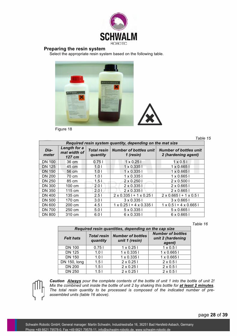
Preparing the resin system Select the appropriate resin system based on the following table.
Figure 18 Table 15
Required resin system quantity, depending on the mat size
Dia-meter
Length for a mat width of 127 cm
Total resin quantity
Number of bottles unit 1 (resin)
Number of bottles unit 2 (hardening agent)
DN 100 36 cm 0.75 l 1 x 0.25 l 1 x 0.5 l DN 125 45 cm 1.0 l 1 x 0.335 l 1 x 0.665 l DN 150 56 cm 1.0 l 1 x 0.335 l 1 x 0.665 l DN 200 70 cm 1.0 l 1 x 0.335 l 1 x 0.665 l DN 250 85 cm 1.5 l 2 x 0.250 l 2 x 0.500 l DN 300 100 cm 2.0 l 2 x 0.335 l 2 x 0.665 l DN 350 115 cm 2.0 l 2 x 0.335 l 2 x 0.665 l DN 400 135 cm 2.5 l 2 x 0.335 l + 1 x 0.25 l 2 x 0.665 l + 1 x 0.5 l DN 500 170 cm 3.0 l 3 x 0.335 l 3 x 0.665 l DN 600 200 cm 4.5 l 1 x 0.25 l + 4 x 0.335 l 1 x 0.5 l + 4 x 0.665 l DN 700 250 cm 5.0 l 5 x 0.335 l 5 x 0.665 l DN 800 310 cm 6.0 l 6 x 0.335 l 6 x 0.665 l
Table 16
Required resin quantities, depending on the cap size
Felt hats Total resin quantity
Number of bottles unit 1 (resin)
Number of bottles unit 2 (hardening
agent) DN 100 0.75 l 1 x 0.25 l 1 x 0.5 l DN 125 1.0 l 1 x 0.335 l 1 x 0.665 l DN 150 1.0 l 1 x 0.335 l 1 x 0.665 l
DN 150, long 1.5 l 2 x 0.25 l 2 x 0.5 l DN 200 1.5 l 2 x 0.25 l 2 x 0.5 l DN 250 1.5 l 2 x 0.25 l 2 x 0.5 l
Caution Always pour the complete contents of the bottle of unit 1 into the bottle of unit 2! Mix the combined unit inside the bottle of unit 2 by shaking this bottle for at least 2 minutes. The total resin quantity to be processed is composed of the indicated number of pre-assembled units (table 16 above).
page 29 of 39
Schwalm Robotic GmbH;; General manager: Martin Schwalm, Industriestraße 16, 36251 Bad Hersfeld-Asbach, Germany Phone +49 6621 79578-0, Fax +49 6621 79578-11, info@schwalm-robotic.de, www.schwalm-robotic.de
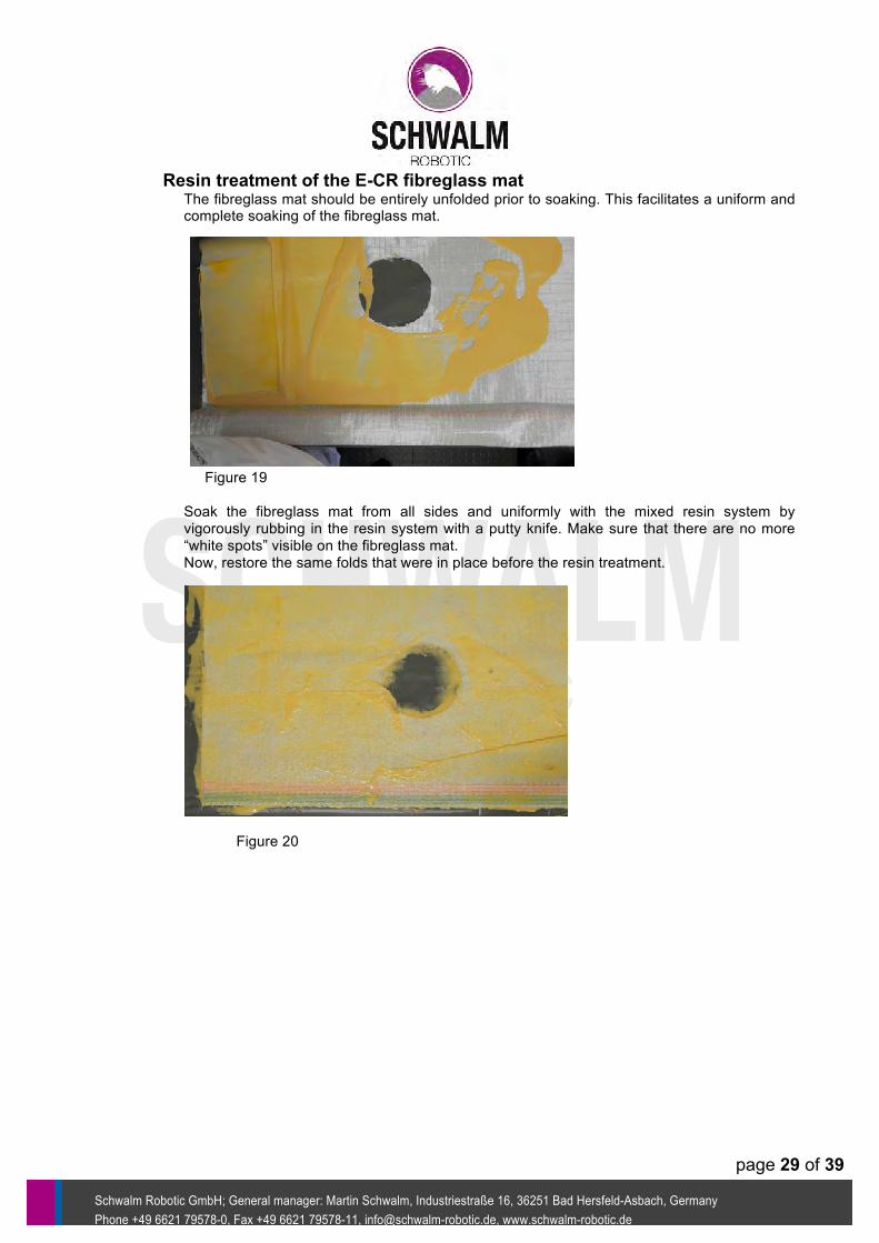
Resin treatment of the E-CR fibreglass mat The fibreglass mat should be entirely unfolded prior to soaking. This facilitates a uniform and complete soaking of the fibreglass mat.
Figure 19
Soak the fibreglass mat from all sides and uniformly with the mixed resin system by vigorously rubbing in the resin system with a putty knife. Make sure that there are no more “white spots” visible on the fibreglass mat. Now, restore the same folds that were in place before the resin treatment.
Figure 20
page 30 of 39
Schwalm Robotic GmbH;; General manager: Martin Schwalm, Industriestraße 16, 36251 Bad Hersfeld-Asbach, Germany Phone +49 6621 79578-0, Fax +49 6621 79578-11, info@schwalm-robotic.de, www.schwalm-robotic.de
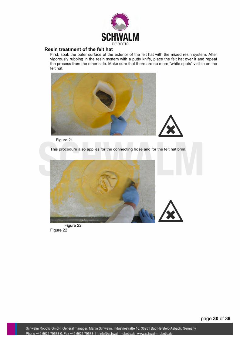
Resin treatment of the felt hat First, soak the outer surface of the exterior of the felt hat with the mixed resin system. After vigorously rubbing in the resin system with a putty knife, place the felt hat over it and repeat the process from the other side. Make sure that there are no more “white spots” visible on the felt hat.
Figure 21
This procedure also applies for the connecting hose and for the felt hat brim.
Figure 22 Figure 22

page 31 of 39
Schwalm Robotic GmbH;; General manager: Martin Schwalm, Industriestraße 16, 36251 Bad Hersfeld-Asbach, Germany Phone +49 6621 79578-0, Fax +49 6621 79578-11, info@schwalm-robotic.de, www.schwalm-robotic.de
Attaching the felt hat Place the resin-soaked felt hat on the rubber hat of the HutlinerPacker® / lateral connection. Fold it up in the connecting hose area.
Figure 23
Attach the fold with a layer of crepe tape about 6 cm away from the upper edge.
Figure 24

page 32 of 39
Schwalm Robotic GmbH;; General manager: Martin Schwalm, Industriestraße 16, 36251 Bad Hersfeld-Asbach, Germany Phone +49 6621 79578-0, Fax +49 6621 79578-11, info@schwalm-robotic.de, www.schwalm-robotic.de
Applying the fibreglass mat Drape the resin-soaked fibreglass mat with the circular cutout centrically to the rubber hat on the HutlinerPacker® / lateral connection.
Figure 25
Attach the resin-soaked fibreglass mat with the layer of crepe tape about 10 cm away from each end of the fibreglass mat, respectively.
Figure 26
Cap profile and fibreglass mat are hence adequately secured against slipping during placement and positioning in the connection area.

page 33 of 39
Schwalm Robotic GmbH;; General manager: Martin Schwalm, Industriestraße 16, 36251 Bad Hersfeld-Asbach, Germany Phone +49 6621 79578-0, Fax +49 6621 79578-11, info@schwalm-robotic.de, www.schwalm-robotic.de
Connect air supplies Connect both air hoses to the HutlinerPacker® / lateral connection. Make sure that the hose with the red marking is connected with the coupling marked in red. The coupling marked in red is intended for filling and emptying the rubber hat. Ventilate the rubber hat before inserting the HutlinerPacker® / lateral connection into the tube.
Figure 27
Parking the milling tool In order to ensure a quick coupling of the milling tool, park the milling tool in the opposing orientation, if possible. Make sure not to bend the cable.
Figure 28

page 34 of 39
Schwalm Robotic GmbH;; General manager: Martin Schwalm, Industriestraße 16, 36251 Bad Hersfeld-Asbach, Germany Phone +49 6621 79578-0, Fax +49 6621 79578-11, info@schwalm-robotic.de, www.schwalm-robotic.de
Lowering the HutlinerPacker® / lateral connections Lower the HutlinerPacker® / lateral connection into the shaft. Make sure that the retaining block points towards the robot. Guide the HutlinerPacker® into the position to be rehabilitated manually or by using a rod.
Figure 29
Caution: If installing the HutlinerPacker® / lateral connection requires entering the sewer system, the necessary safety measures must be taken in advance. This includes in particular: Donning the PPE, donning the safety and rescue harness, mounting the tripod, testing for gas in the sections to be entered, a second person for safety reasons.
Coupling the milling tool Guide the milling tool placed inside the tube towards the HutlinerPacker® / lateral connection and couple the retaining plate of the milling tool to the retaining block of the HutlinerPacker® / lateral connection.
Figure 30

page 35 of 39
Schwalm Robotic GmbH;; General manager: Martin Schwalm, Industriestraße 16, 36251 Bad Hersfeld-Asbach, Germany Phone +49 6621 79578-0, Fax +49 6621 79578-11, info@schwalm-robotic.de, www.schwalm-robotic.de
Transporting the packer In order to comply with the pot life of the resin system, slide the HutlinerPacker® / lateral connection to the damaged area immediately. In order to pivot the HutlinerPacker® / lateral connection to a certain orientation, turn it during the sliding movement. If you have already arrived at the damaged area, perform short back and forth sliding movements and simultaneously pivot the HutlinerPacker® / lateral connection.
Figure 31
Threading the felt hat Once the position with respect to length and orientation of the damaged area is achieved, the rubber cap engages with the felt hat. Perform short back and forth sliding movements of the milling tool and the coupled HutlinerPacker® / lateral connection in order to optically determine the connection’s centre point.
Figure 32
page 36 of 39
Schwalm Robotic GmbH;; General manager: Martin Schwalm, Industriestraße 16, 36251 Bad Hersfeld-Asbach, Germany Phone +49 6621 79578-0, Fax +49 6621 79578-11, info@schwalm-robotic.de, www.schwalm-robotic.de
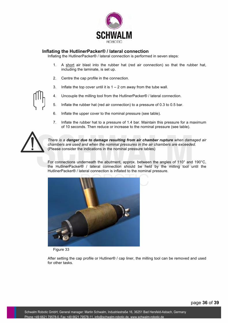
Inflating the HutlinerPacker® / lateral connection Inflating the HutlinerPacker® / lateral connection is performed in seven steps: 1. A short air blast into the rubber hat (red air connection) so that the rubber hat,
including the laminate, is set up. 2. Centre the cap profile in the connection. 3. Inflate the top cover until it is 1 – 2 cm away from the tube wall. 4. Uncouple the milling tool from the HutlinerPacker® / lateral connection. 5. Inflate the rubber hat (red air connection) to a pressure of 0.3 to 0.5 bar. 6. Inflate the upper cover to the nominal pressure (see table). 7. Inflate the rubber hat to a pressure of 1.4 bar. Maintain this pressure for a maximum
of 10 seconds. Then reduce or increase to the nominal pressure (see table). There is a danger due to damage resulting from air chamber rupture when damaged air chambers are used and when the nominal pressures in the air chambers are exceeded. (Please consider the indications in the nominal pressure tables) For connections underneath the abutment, approx. between the angles of 110° and 190°C, the HutlinerPacker® / lateral connection should be held by the milling tool until the HutlinerPacker® / lateral connection is inflated to the nominal pressure.
Figure 33
After setting the cap profile or Hutliner® / cap liner, the milling tool can be removed and used for other tasks.

page 37 of 39
Schwalm Robotic GmbH;; General manager: Martin Schwalm, Industriestraße 16, 36251 Bad Hersfeld-Asbach, Germany Phone +49 6621 79578-0, Fax +49 6621 79578-11, info@schwalm-robotic.de, www.schwalm-robotic.de
Lowering the HutlinerPacker® / lateral connection Once the determined deshelling time has completely expired, the air can be released from the pressure chambers of the HutlinerPacker® / lateral connection. In order to prevent damage to the rubber hat, it is mandatory to comply with the sequence for emptying the air chambers: 1. Release all pressure from the rubber hat (red air connection) 2. Release all pressure from the packer. The HutlinerPacker® / lateral connection can now be pulled out at both air tubes. It is not necessary to pick up the HutlinerPacker® / lateral connection with the milling robot.
Acceptance The next step is the acceptance inspection, which is performed using a camera. The rehabilitation operation is registered and reported.

page 38 of 39
Schwalm Robotic GmbH;; General manager: Martin Schwalm, Industriestraße 16, 36251 Bad Hersfeld-Asbach, Germany Phone +49 6621 79578-0, Fax +49 6621 79578-11, info@schwalm-robotic.de, www.schwalm-robotic.de
Control and maintenance
Hazard of rupture! A function test of the air chambers of the HutlinerPacker® / lateral connection may only be performed inside the pipelines. Hazard of rupture! Indications about maximum pressure for the HutlinerPacker® / lateral connection and the rubber hats only refer to the working state in situ inside the sewer. Outside the pipelines, the HutlinerPacker® / lateral connections may only be pressurized up to a maximum of 0.2 bar for visual inspection.
Table 17
Device Control / maintenance interval
HutlinerPacker® / lateral connection
Air chambers
Before and after every application Visual inspection
At least every three months Function test
Connections Before and after every application Visual inspection
Mechanical pieces
At least once a year Visual inspection At least every three
months Inspection of all hose
connections At least every three
months Inspection of all hose
binders
Pressure regulator
Before and after every application Visual inspection
At least every three months Function test
Air hoses
Before and after every application Visual inspection
At least every three months Function test
Caution During the visual inspections of the air chambers, special attention should be paid to cracks, abrasions and surface changes. Caution After every application, the HutlinerPacker® / lateral connections, rubber hats and the all equipment used must be cleaned with a neutral cleaner and dried for storage. For storing the HutlinerPacker® / lateral connections, the upper cover should be slightly pressurized.

page 39 of 39
Schwalm Robotic GmbH;; General manager: Martin Schwalm, Industriestraße 16, 36251 Bad Hersfeld-Asbach, Germany Phone +49 6621 79578-0, Fax +49 6621 79578-11, info@schwalm-robotic.de, www.schwalm-robotic.de
Accessory list
Table 18 Designation Order number Coverall white 2500-010-1017-001
Nitrile-covered gloves 0000002881, 0000005925, 0000005924
Safety goggles 2500-010-1019-001 Rubber hat seal (packet of 10) 0000001714
PE bag 0000001149 Rubber bands DN 50 (packet of 10) 0000003403 Rubber bands DN 80 (packet of 10) 0000001758 Rubber bands DN 100 (packet of 10) 0000001978 Rubber bands DN 160 (packet of 10) 0000004198 Rubber bands DN 200 (packet of 10) 0000003143 Rubber bands DN 260 (packet of 10) 0000003404
Putty knife 195 mm VA 2500-020-1021-001 PE wrapping film 0000001098
Separating and care agent for rubber 0000001177 Subject to technical modifications. Issued: 13 December 2007 Updated: 18 July 2016