preparation of oriented, fully hydrated lipid samples for...
TRANSCRIPT

5
Preparation of Oriented, Fully Hydrated Lipid Samples for Structure Determination Using X-Ray Scattering
Stephanie A. Tristram-Nagle
SummaryThis chapter describes a method of sample preparation called “the rock and roll method,” which is basically a
solvent evaporation technique with controlled manual sample movement during evaporation of solvent fromlipid/solvent mixtures that produces well-oriented thick stacks of about 2000 lipid bilayers. Many lipid types havebeen oriented using different solvent mixtures that balance solubilization of the lipid with uniform deposition of thelipid solution onto solid substrates. These well-oriented thick stacks are then ideal samples for collection of bothX-ray diffraction data in the gel phase and X-ray diffuse scattering data in the fluid phase of lipids. The degree oforientation is determined using visual inspection, polarizing microscopy, and a mosaic spread X-ray experiment.Atomic force microscopy is used to compare samples prepared using the rock and roll method with those preparedby spin-coating, which produces well-oriented but less homogeneous lipid stacks. These samples can be fullyhydrated through the vapor provided that the hydration chamber has excellent temperature and humidity control.
Key Words: AFM; hydration; mosaic spread; oriented lipid bilayers; polarizing microscopy; rock and rollmethod; X-ray scattering.
1. IntroductionLipid bilayers form the underlying structure of every plant and animal cell membrane
wherein, in general, they occur in a fluid, fully hydrated state. Whereas X-rayed, multilamel-lar arrays of lipid bilayers produce sharp Bragg diffraction peaks only in the lower-tempera-ture crystalline phases due to their well-ordered structure (1), fluid phase lipid bilayersproduce diffuse scattering in the fully hydrated state due to thermal fluctuations in the waterspace between fluctuating bilayers (for a review, see ref. 2). The Nagle laboratory pioneereda diffuse scattering technique that collects and analyzes two-dimensional (2D) diffuse X-rayscattering from fully hydrated, fluid-phase lipid stacks oriented onto a solid substrate (3–5).These data yield structural and material parameters about specific lipids, but require thicksamples (~4–10 µm) since diffuse scattering is weaker than sharp, Bragg diffraction peaks.This chapter will present the step-by-step procedures of how to prepare oriented, thick bilayersample films and how to hydrate them.
The name “rock and roll method” derives from the popular culture; it was borrowed sinceit describes well the procedure for making oriented stacks of lipid bilayers first published bythe lab in 1993 (6). The appropriate amount of dry lipid to form a 10-µm thick film (see Note 1and Subheading 3.1., step 1) is dissolved in the appropriate solvent(s). The choice of sol-vent(s) depends on the lipid chain length, unsaturation, backbone, and headgroup type, and iscrucial for the success of the films (see Subheading 3.1., step 3). The lipid solution ispoured onto one of the substrates (see Subheading 2., step 3), which is hand-rocked in four
From: Methods in Molecular Biology, vol. 400: Methods in Membrane LipidsEdited by: A. M. Dopico © Humana Press Inc., Totowa, NJ
63
05_Tristram-Nagle 6/28/07 9:40 PM Page 63

directions (N, S, E, and W), forcing the lipid solution to roll out to the edges of the substrate.These actions subject the lipid bilayers to shear force, which helps them orient during evap-oration of the solvent. The rock and roll procedure requires a large glove box to producedefect-free films, because a solvent-rich vapor slows down the evaporation of solvent fromthe films (see Subheading 3.3. and Note 2).
The rock and roll procedure is compared herein with two other methods that were previ-ously used to form thin films (~20 bilayers):
1. A simple stationary solvent evaporation technique described in detail by Seul and Sammon (7)(see Subheading 3.4.).
2. A “high-tech” method called spin-coating (8) (see Subheading 3.5.).
A third method published recently (9) that codissolves solid naphthalene with the solventsand lipid, renders well-aligned and easily hydrated thick lipid films. However, it was deemedunsuitable for the analysis because the resulting films contain many small holes, which pre-clude an accurate estimation of the sample thickness.
2. Materials1. Lipids: most lipids are purchased from Avanti Polar Lipids (Alabaster, AL) due to their
high purity and, more recently, low acyl-chain migration in mixed chain lipids. Occasionally,novel lipids are synthesized for the Nagle lab by collaborators; these are checked by electrosprayionization mass spectrometry to verify their purity. Lyophilized lipids are stored at –20°C intheir original vials in dessicators before use. The original vials are equilibrated at room temper-ature for at least 15 min before opening to avoid condensation of water into the lipid, which canlead to hydrolysis of chains. When stored and opened this way, the saturated chain lipids do notdegrade for many years, as verified using thin-layer chromatography (46:15:3,chloroform:methanol:7 N NH4OH [v:v:v]), stained with molybdic acid stain (10).
2. Solvents: solvents are of high-pressure liquid chromatography grade; purity of the solventsand cleanliness in forming the sample films are essential. Solvents are poured from the originalsolvent container into disposable 20-mL glass scintillation vials, which are discarded after 1 d ofsample preparation.
3. Substrates: usually a 1-mm thick silicon wafer (100 face) cut to 1.5 × 3 cm2 is used. The sizeof the wafer is cut to be the same as the size of the Peltier cooler (Melcor, Trenton, NJ) thatsupports the silicon wafer during the hydration experiment, so that the sample is cooled evenly(see Subheading 3.7.). The silicon wafers can be used with or without dopant. The first substratethat was used with some success for gel phase samples was a glass microscope slide. Microscopeslides have the advantage that orientation can be checked easily using a polarizing microscope(see Subheading 3.4.); however, the diffuse background from this substrate is large and noteasily subtracted from the fluid phase diffuse data. Alternatively, the substrate is a 3 × 3 cm2
piece of freshly cleaved 35-µm thick mica (Mica New York Corp, NY), which can be curved andglued onto a cut, glass beaker. Another type of substrate is a thin (70 µm) 3 × 3 cm2 00 glasscover slip (Precision Glass and Optics, Santa Ana, CA).
4. Water: nanopure water is used to hydrate the lipids from the vapor phase in a freshly cleanedhydration chamber (described in Subheading 3.7.). Water purity and cleanliness of the chamberare essential to reach full hydration.
3. Methods3.1. Preparation of Samples
1. To calculate the mass of lipid required to make a 10-µm film, consider a 10-µm thick columnof many copies of a single lipid pair in a bilayer stack. Convert to number of molecular bilay-ers by dividing by the thickness of a dried lipid bilayer (compare with ~60 Å for dried
64 Tristram-Nagle
05_Tristram-Nagle 6/28/07 9:40 PM Page 64

dipalmitoylphosphatidylcholine [DPPC]). Determine the total number of lipids in the film byfirst multiplying the aforementioned number of bilayers by two, then dividing by the surfacearea of a dried lipid (~50 Å2), and then multiplying by the total surface area of the substrate.Then divide by Avogradro’s number to get moles, and multiply by the gram molecular weightof the lipid to get grams of lipid. The actual thickness of these films measured by atomic forcemicroscopy (AFM) is slightly smaller than the calculated thickness, presumably because ofsome collection of lipid near the edges of the substrate (11).
2. Weigh lyophilized lipid using an analytical balance and place the lipid (~4–10 mg, calculated asaforementioned) into a disposable, small glass test tube. Disposable test tubes are used to assurecleanliness. Add 100–200 µL solvent to the weighed lipid in the test tube in the glove box.Agitate the tube to solubilize the lipid. The solvents required for each lipid were determined bythe method of trial and error, within the general guidelines that a hydrophobic solvent is neededto dissolve the lipid, whereas an amphipathic solvent is needed to decrease the contact angle ofthe lipid solution with the hydrophilic substrate, thus causing the solution to spread. Often onesolvent is not sufficient to both solubilize the lipid and cause the solution to spread on the sili-con, mica, or glass surface. Listed below are the solvents or solvent mixtures (shown as volumeratios), which were successful for each lipid in the lab. Results may vary across laboratories dueto relative humidity, temperature, and size (or lack) of the glove box (see Note 2). If the solventsbelow do not successfully form a smooth-looking film to the naked eye on the first attempt, thena different ratio may be used to redissolve the film.
3. Suggested solvents for specific lipids:a. Dioleoylphosphatidylcholine (DOPC)—easiest lipid to orient. 2:1, 2.5:1, or 3:1 chloroform:
methanol, or 1:1 chloroform: trifluoroethanol (TFE).b. Dilauroylphosphatidylcholine (DLPC)—difficult to orient. 1:1:1 chloroform:methanol:TFE.c. Dimyristoylphosphatidylcholine (DMPC)—chloroform:TFE 1:1 or 2:1, chloroform:methanol
1:1 or 1.5:1, and neat isopropanol.d. DiC15phosphatidylcholine—chloroform:methanol 2.5:1.e. Dipalmitoylphosphatidylcholine (DPPC)—chloroform:methanol 2–3.5:1.f. D,L-DPPC—chloroform:methanol 2:1.g. DiC17phosphatidylcholine—chloroform:methanol 3:1.h. Distearoylphosphatidylcholine (DSPC)—chloroform:methanol 2:1 or 3:1.i. DiC19phosphatidylcholine—chloroform:methanol 2.5:1, methanol:carbon tetrachloride 5:1.j. DiC20phosphatidylcholine—methanol:carbon tetrachloride 4:1.k. DiC22phosphatidylcholine—methanol:carbon tetrachloride 4:1.l. DiC24phosphatidylcholine—difficult to orient. Methanol:carbon tetrachloride 3:1 and chlo-
roform:methanol 2:1.m. DSPC-Br4—chloroform:TFE, 1:1.n. Dihexadecylphosphatidylcholine (DHPC)—chloroform:methanol 2:1.o. Dierucoylphosphatidylcholine DiC22:1PC—chloroform:TFE, 1:1.p. Palmitoyloleoylphosphatidylcholine (POPC)—chloroform:TFE, 1:1.q. Dimyristoylphosphatidylserine (DMPS)—difficult to orient. TFE:toluene, 4:1, or neat toluene.r. Dioleolyphosphatidylserine (DOPS)—chloroform:TFE, 2:1.s. Stearoyldocosahexaenoylphosphatidylcholine—methylene chloride:methanol, 3:1.t. Stearoyldocosapentaenoylphosphatidylcholine—methylene chloride:methanol, 3:1.u. Dilaurylphosphatidylethanolamine (DLPE)—neat hexafluoroisopropanol in the hood (see
Note 3).v. Myristoylpalmitoylphosphatidylcholine (MPPC)—chloroform:methanol, 2:1.w. Myristoylstearoylphosphatidylcholine (MSPC)—chloroform:methanol, 2.5:1.x. 1,2-Di-O-myristoyl-3-N,N,N-trimethylaminopropane (DM-TAP)—chloroform:methanol, 10:1.y. Most mixtures combining DOPC, DPPC, DLPC, brain sphingomyelin, and cholesterol (raft
and super lattice mixtures)—chloroform:TFE, 1:1 (see Note 4).
Rock and Roll Method 65
05_Tristram-Nagle 6/28/07 9:40 PM Page 65

z. Mixtures with alamethicin and DOPC or DOPC-Br4—chloroform, then redissolved in chlo-roform:TFE, 1:1.
aa. Mixtures with human immunodeficiency virus fusion peptide FP-23 and DOPC ordiC22:1PC—neat hexafluoroisopropanol, in the hood (see Note 3).
Salts can be added to any of the aforementioned lipid–solvent mixtures. Salts crystallize ondrying, yet they diffuse readily between bilayers on subsequent hydration (see Subheading 3.7.)(see also ref. 12). In the glove box, close the test tube prepared with above-containing solventand lipid, with a silicone or neoprene stopper during the following preparation of the substrate,so that the ratio of solvents does not change due to unequal evaporation. Rubber stoppersshould not be used as they are degraded by the solvents.
3.2. Preparation of the Substrates
The normal procedure is to simply bathe the Si wafers in chloroform in a glass Petri dishinside the glove box; then, the wafers are rubbed with a cotton swab (see Note 5). This pro-cedure not only cleans the wafer, but also fills the glove box with a chloroform-saturatedatmosphere. The Si wafers are sometimes rubbed with a Kimwipe in the final step to removeany remaining residue, and any lint is carefully blown away with a small rubber bulb. Whenmica is used, the 3 × 3 cm2 piece is freshly cleaved using a technique shown to the author byJacob Israelachvilli; this consists of wedging a fine gauge needle or pin into the edge of asquare of grade 2 mica to separate a thin layer of mica from the original slab, which is thenslowly teased away using a tweezer. The thickness should be about 35 µm (i.e., flexibleenough to become slightly curved, yet thick enough to contain lipid and solvent), with nocracks or holes. The mica should be used within 1 or 2 h after cleaving to avoid dust collect-ing on its surface.
The third substrate, i.e., 3 × 3 cm2 thin glass cover slips, should be cleaned with chloroformswabbing as for the silicon wafer. At just 70-µm thick, these cover slips break easily, especiallyduring cleaning. The thin glass cover slip is useful for X-raying lipid samples through the backof the glass at a 45° angle of incidence; the scattering from the sample is then totally unob-structed by the substrate, which is not the case for a grazing angle of incidence on the siliconwafer or curved mica. These substrates are then attached to the cap of a 20-mL disposableglass scintillation vial using either sticky tack or clay (see Fig. 1). This method of attachmentleaves the sides of the substrate completely free, which is essential to allow surface tension andhold the solvent solution on the top of the substrate. If the substrates are placed directly ontoa larger substrate, such as a microscope slide, the lipid–solvent mixture tends to run off at theedges, due to a small contact angle of the lipid solution with the substrate.
3.3. Rock and Roll Method
When the author first began making films in the early 1990s, she tried to evaporate the sol-vents in the hood, but rapid evaporation of the solvent caused many surface defects (a frostedappearance) that were poorly oriented. Even working on the open lab bench close to an openwindow or air conditioner caused the lipid surface to become “frosty” during evaporation ofthe solvent. Therefore, investment in a suitable glove box is key for the success of thismethod. The Nagle lab glove box is 8 ft3 made from 3/16 in. thick Plexiglas, with rubber,gloveless ports for entry of hands. Humidity is monitored with a probe (Rotronics, Dallas,TX), but not controlled. The humidity generally increases from about 40 to 70% relative
66 Tristram-Nagle
05_Tristram-Nagle 6/28/07 9:40 PM Page 66

humidity (RH) during the film formation, because of perspiration from human hands in theglove box (see also Note 2).
In the glove box, the lipid in solvent is poured onto the substrate attached as described inSubheading 3.2., with rocking and rolling (see Subheading 1.). As the sample dries, a higherangle of rocking (up to 90°) may be required in order to induce the now-viscous solution tomove down the wafer. The rocking continues until the rolling of lipid in solvent over the sur-face stops; at this point the substrate is removed from the sticky tack and placed onto a flatsurface in the glove box, which is why flat substrates work best (although the author hasalso used a hanging drop rock and roll method on an inverted curved beaker). The entireprocess takes about 5 min. Rotating the substrate on the sticky tack before detaching itavoids breaking the thinner substrates. The film is left to dry for 1 d in the glove box and anadditional day in air on the lab bench or in a fume hood to assure complete removal of solvent (see Note 6).
3.4. Assessment of Orientation
After the sample on mica or glass cover slip has dried for at least 1 d on the lab bench, itis first examined by eye; gross misorientation appears as large holes, crusted lipid, and afrosted appearance. If there is no evidence of gross misorientation, the sample is examinedusing an optical microscope under crossed polarizers as described by Asher and Pershan (13).
Rock and Roll Method 67
Fig. 1. A silicon substrate (15 × 30 mm2) is attached through sticky tack (synthetic clay) to a 20-mLscintillation vial. (Left) Side view, (Right) top view. The highly polished silicon surface appearsblack in this photograph.
05_Tristram-Nagle 6/28/07 9:40 PM Page 67

If the film is completely smooth, well oriented, and homogeneous, there will be a uniformblack field under crossed polars. Any defects retard the light along the defect, whichresults in loss of total cancellation of crossed polarized light, giving a bright spot orstreak. Many curious and astonishing structures have been observed by the author and herstudents (see also Note 7). The sample in Fig. 2 was prepared by pouring DPPC solubi-lized in 3:1 chloroform:methanol onto a cleaned glass microscope slide; this was rockedbriefly to evenly distribute the lipid solution over the substrate. It was then left to dry on thelab bench without any further movement, similar to the procedure of Seul and Sammon (7),except that the amount of lipid in this sample was for a 10-µm thick film. The visualappearance of the film after drying on the lab bench is shown in Fig. 2A. The various partsof the same film visualized under crossed polars in the optical microscope are shown inFigs. 2B–D. A photograph of a sample prepared using the rock and roll procedure is shownin Fig. 6.
Once the sample appears uniform under crossed polars, it can be X-rayed either in thedried or hydrated state using the lab-rotating anode or during the synchrotron experiment.The measurement of mosaic spread is obtained by rotating the flat sample in 0.005° stepsthrough a chosen Bragg θ angle. The Bragg peak intensity is measured and plotted vs angleof rotation. This is fit with a Gaussian function, and the sigma of the Gaussian function isreported in degrees as the mosaic spread. An example of a rocking scan to determine mosaicspread is shown in Fig. 3.
68 Tristram-Nagle
Fig. 2. (A) Visual appearance of a sample of DPPC dried from chloroform:methanol (3:1) onto acleaned, stationary glass microscope slide. (B–D) Defects observed using crossed polars in the opticalmicroscope on the far left side of the sample shown in A. The lipid in the center of the slide appeareddark gray under crossed polars, i.e., fairly well oriented but not uniform. Lipid was not deposited on thefar right side of the slide. Results like these were the motivation for the rock and roll procedure.
05_Tristram-Nagle 6/28/07 9:40 PM Page 68

3.5. AFM to Characterize Uniformity and Smoothness of Sample Films
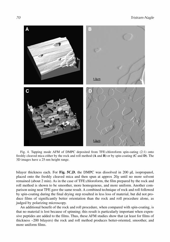
With the help of Justin Legleiter, a talented graduate student in Chemistry at CarnegieMellon University, the author used AFM to probe microscopic differences between lipidfilms prepared using the rock and roll procedure, with those using spin-coating. Detailsof the tapping mode AFM are presented in ref. 11. Many variables such as spinningspeed, method of application of the lipid in solvent (dropwise or stationary), concentra-tion of lipid in solvent, and choice of solvent were attempted. The samples shown belowin this comparison study were deposited on 3 × 3 cm2 pieces of freshly cleaved mica andthe thicknesses were approx 200 bilayers. The AFM 3D and the phase images of a 1.1mg DMPC sample dissolved in 100 µL TFE:chloroform (2:1), and prepared using therock and roll method are shown in Fig. 4A,B, respectively. Three steps of one bilayerthickness are shown in the lower right-hand corner of both Fig. 4A,B. These are some-times called edge dislocations. The corresponding images for a sample prepared byspin-coating are shown in Fig. 4C,D. The sample was 0.94 mg of DMPC in 100 µLTFE:chloroform (2:1), added drop-by-drop as the sample was spinning at approx 20g.The main difference between the images in Fig. 4 is that in the spin-coated sample thereare many large holes, and several protrusions of one or more bilayers. Although the lipidappears to be flat and well oriented in Fig. 4C,D, the film is less homogeneous and exten-sive than that in Fig. 4A,B.
Another comparison of these two methods was carried out using the neat solvent, isopropanol,first reported by Seul and Sammon (7). Figure 5A,B show the 3D and phase images of aDMPC sample (1.2 mg DMPC dissolved in100 µL isopropanol) prepared by the rock and rollmethod. The figure shows that the surface is quite smooth, with four extensive steps of one
Rock and Roll Method 69
Fig. 3. Mosaic spread of a 10-µm thick DMPC sample oriented onto a silicon wafer. This rockingscan was centered on the second order Bragg reflection from a lamellar stack of hydrated bilayers.Each data point was collected at a separate angle of incidence. The half-width of the Gaussian fit(solid line) is 0.08°.
05_Tristram-Nagle 6/28/07 9:40 PM Page 69
bilayer thickness each. For Fig. 5C,D, the DMPC was dissolved in 200 µL isopropanol,placed onto the freshly cleaved mica and then spun at approx 20g until no more solventremained (about 2 min). As in the case of TFE:chloroform, the film prepared by the rock androll method is shown to be smoother, more homogenous, and more uniform. Another com-parison using neat TFE gave the same result. A combined technique of rock and roll followedby spin-coating during the final drying step resulted in less loss of material, but did not pro-duce films of significantly better orientation than the rock and roll procedure alone, asjudged by polarizing microscopy.
An additional benefit of the rock and roll procedure, when compared with spin-coating, isthat no material is lost because of spinning; this result is particularly important when expen-sive peptides are added to the films. Thus, these AFM studies show that (at least for films ofthickness ~200 bilayers) the rock and roll method produces better-oriented, smoother, andmore uniform films.
70 Tristram-Nagle
Fig. 4. Tapping mode AFM of DMPC deposited from TFE:chloroform spin-oating (2:1) ontofreshly cleaved mica either by the rock and roll method (A and B) or by spin-coating (C and D). The3D images have a 25-nm height range.
05_Tristram-Nagle 6/28/07 9:40 PM Page 70

3.6. Packing Samples
The sample on the 1.5 × 3 cm2 silicon wafer is then trimmed to a thin strip of 4 or 5 ×30 mm2 long, by removing sample along both long edges of the silicon wafer using a freshsingle-edge razor blade, followed by wiping off any remaining lipid with a dry cottonswab. One reason for trimming the samples is to remove lipid that may be less well ori-ented near the edges of the wafer. The other reason concerns the X-ray experiment (5).The trimmed samples are stored in multicompartment plastic boxes within a large glassdessicator at 4°C. The samples are usually prepared 1–3 wk before a synchrotron trip, butsamples on all three substrates are quite stable for several months when stored in a dessi-cator at 4°C. They are carried to the Cornell high-energy synchrotron source (CHESS) inthe dessicator in an ice-filled container. A picture of a sample prepared in this way isshown in Fig. 6.
Rock and Roll Method 71
Fig. 5. Tapping mode AFM of DMPC from isopropanol deposited onto freshly cleaved mica eitherby the rock and roll method (A and B) or by spin-coating (C and D). Height ranges were 25 and50 nm for 5A,C, respectively.
05_Tristram-Nagle 6/28/07 9:40 PM Page 71

3.7. Sample Hydration Through the Vapor
Hydration of lipid bilayers through the vapor phase has been difficult (14). To summarizebriefly, although it was possible to fully hydrate gel phase bilayers through the vapor(6,15,16), it was at first impossible to hydrate through the vapor in the more biologicallyrelevant fluid phase (17,18). The seeming paradox (i.e., that the vapor above pure water is notat 100% relative humidity even though it is in equilibrium with pure water) generated contro-versy in several labs (19). The trick that worked in the gel phase was to cool the samplerelative to the surrounding vapor using a Peltier cooler under the sample substrate (6); how-ever, this solution was not sufficient to condense the considerably higher water content intoa fluid phase lipid. The key to successfully hydrating a sample through the vapor was excel-lent temperature control; when this is done, the vapor pressure paradox does not exist (19,20).The researchers have been fortunate to be able to use two X-ray chambers for hydrating lipidsin the fluid phase. The details and pictures of these chambers are described in refs. 5 and 21and will not be repeated in this chapter. One important design feature is a rapid flow to thechamber of the coolant that is temperature-controlled by an external water bath. In addition,thick or double walls (double 6-µm thick mylar windows for entry and exit of X-rays) and additional foam insulation on the outside of the chamber for extreme tempera-tures (>50°C and <10°C) are needed. A final important feature is to add a water-filled pieceof filter paper (suggestion of Peter Rand) to the inside top of the chamber with fingers thatextend into the hydrating water reservoir. This increases the water evaporation surface andhelps to decrease hydration equilibration times. When the Peltier current under the sample isset to cool the sample by 0.1°C relative to the hydration chamber temperature (5), hydrationat 30°C occurs in about 30 min. If a slower hydration is desired (as when collecting data atmany D-spacings within 10 Å of full hydration), a smaller current is used. The current canalso be reversed to slow down the hydration or slightly dry out the sample by heating the sur-face of the Peltier in contact with the sample. Controlling the hydration speed and extent this
72 Tristram-Nagle
Fig. 6. DPPC dissolved in chloroform:methanol (3.5:1) was oriented onto a silicon substrate usingthe rock and roll procedure and trimmed as described in Subheading 3.6.
05_Tristram-Nagle 6/28/07 9:40 PM Page 72

way was a huge achievement, allowing data collection of many samples during a single tripto CHESS.
The chamber uses flat samples, which are rotated during the X-ray data collection.Alternatively, mica can be used as substrate (described in Subheading 2., step 3). The micawith lipid sample is curved and glued onto a cut, 50-mL glass beaker. Devcon 5 min epoxyand clamps are used to hold the mica in place during the drying of the epoxy. Since the sam-ple is curved, all the angles of incidence that are obtained by rotating a flat sample can beobtained in one scan at a grazing angle of incidence. The cut, glass beaker sits on a semicylin-der of solid aluminum, which is in contact with the Peltier cooler (see Fig. 7). One smalldrawback to using this sample is that there are several sharp and intense mica reflections thatare difficult to subtract out with a background scan, resulting in their inclusion in the finaldata. However, as the diffuse background scattering from mica is very low, these sharp peakswere found to be acceptable.
4. Notes1. Thicker films up to 40 µm were attempted, but the mosaic spread, or degree of misorientation,
increased. Thinner films were tried (2 µm), but the intensity of diffuse scattering was reducedsubstantially when compared with the reflectivity from the substrate and general background.Films between 4 and 10 µm are a compromise between satisfactory X-ray signal-to-noise andlow mosaic spread. However, films less than 8 µm are sometimes not successful because thereis not enough lipid to cover the surface homogeneously.
2. When teaching the rock and roll method to colleagues, the author reached success only when asuitable glove box was available. The use of a small, plastic disposable glove box was notsuccessful because the atmosphere in the glove box rapidly became too humid due to perspiration
Rock and Roll Method 73
Fig. 7. DPPC dissolved in 2:1 chloroform:methanol is deposited onto mica, which is glued to acut, glass, 50-mL beaker. This is in contact with a curved aluminum holder; Dow heat sink compoundis normally spread under the beaker for better thermal contact during the hydration experiment.There is a Peltier cooler under the sample (not visible); a second Peltier cooler is shown to the rightof the holder as a demonstration. An alternate sample holder for flat silicon substrates does not havethe semicylindrical aluminum piece.
05_Tristram-Nagle 6/28/07 9:40 PM Page 73

from the hands. The use of thin neoprene gloves is possible, yet somewhat awkward, given thenecessary manipulations. Even in a large glove box, the humidity sometimes rises above 80%RH when gloves are not worn. If this occurs, then the ratio of the hydrophobic/hydrophilic sol-vent should be increased: for example, chloroform:TFE, from 1:1 to 2:1.
3. Hexafluoroisopropanol’s label warns that it is dangerous to all organs. Wear neoprene gloves and workwith this solvent in the hood only. This procedure is different from use of the glove box described inSubheading 3.3., but this solvent is unique in that it can produce quite uniform films while dryingquickly. This solvent is only successful for some lipids and should be avoided if possible.
4. Films formed from cholesterol mixtures are usually not as well oriented as phospholipids, butthe orientation of mixtures of lipids and cholesterol is improved by annealing at 10–20°C abovethe main phase-transition temperature of the highest melting lipid. This is carried out in a humidenvironment in an annealing chamber with a water-filled sponge attached above and below thelipid sample for 6–12 h.
5. For cleaning the silicon wafers, the author has tried a chromic acid wash, followed by copiousrinsing with Barnstead/Thermolyne (Dubuque, IA) nanopure water, then an HCl wash, followedby copious rinsing with Barnstead nanopure water, with or without a final step of swabbing withhigh-pressure liquid chromatography chloroform using a cotton swab. The results are similarwith or without the two acid washes before the chloroform swabbing. The final step of chloro-form swabbing imparts a slightly hydrophobic surface to the wafers, which is beneficial. On oneoccasion the author tried to save time by using a solution of hot, concentrated Contrad (DeconLabs, King of Prussia, PA). This is a basic surfactant solution that is used for washing glassware,which was recommended by a colleague. This was nearly disastrous: the Contrad etched thesilicon wafer surface so that it lost its shine; this was not restored with a hydrofluoric acid dip,as used for the removal of a silicon oxide layer. The mosaic spread from lipid samples preparedon these wafers was worse than that with the normal chloroform swabbing technique, and therewas a large diffuse scatter from these substrates, similar to that from glass substrates. Therefore,it is best not to aggressively clean the polished silicon wafer surface.
6. Some care is needed to master the rock and roll technique. The rocking should be slow and shal-low at first, when there is still much of the solvent on the substrate. Excessive rocking at thistime can cause the lipid solution to fall off the edges of the substrate. The angle and speed ofrocking can be increased as the sample dries. Rocking too slowly at this time, or not forcing thelipid solution to roll out to the edges of the substrate, produces a poorly oriented sample.
7. Defects can be described as volcanoes, feathers, tubules, squigglies, simple crosses, and fattystreaks. If there is water present, a familiar “Maltese cross” appears because of the circular shapeof the multilamellar vesicles that retard the light in a radial fashion (22). If Maltese crosses areobserved, the sample is not well oriented and should be discarded. Simple crosses are moreprominent if the methanol content of the solvent mixture is too high, and squigglies and feath-ers are more prominent when the chloroform content of the solvent mixture is too high.Squigglies and feathers are more disruptive than a surface layer of methanol-induced simplecrosses. Another feature, termed “Grandjean terraces” and described nearly 100 yr ago (23),looks like steps or plateaus (see Figs. 4A,B and 5A,B). These edge dislocations, unlike in thethin films of Seul and Sammon (7), do not degrade the orientation of the sample, probablybecause they are largely confined just to the outer surface of thick films.
AcknowledgmentsI would like to thank my husband and colleague, Prof. John Nagle, for continued col-
laboration and support, and Dr. Norbert Kucerka for supplying the mosaic spread graph.I would also like to thank Dr. Horia Petrache for help with construction of the hydrationchamber described in ref. 5. Supported by National Institutes of Health grant no.GM44976 (JFN).
74 Tristram-Nagle
05_Tristram-Nagle 6/28/07 9:40 PM Page 74

References
1. Luzzati, V. (1968) X-Ray Diffraction Studies of Lipid-Water Systems, in Biological Membranes,(Chapman, D., ed.), Academic Press, London, pp. 71–123.
2. Tristram-Nagle, S. and Nagle, J. F. (2004) Lipid Bilayers: Thermodynamics, structure, fluctua-tions, and interactions. Chem. Phys. Lipids 127, 3–14.
3. Lyatskaya, Y., Liu, Y., Tristram-Nagle, S., Katsaras, J., and Nagle, J. F. (2001) Method for obtain-ing structure and interactions from oriented lipid bilayers. Phys. Rev. E 63, 011907(1–9).
4. Liu, Y. and Nagle, J. F. (2004) Diffuse scattering provides material parameters and electron den-sity profiles of biomembranes. Phys. Rev. E 69, 040901(R).
5. Kucerka, N., Liu, Y., Chu, N., Petrache, H. I., Tristram-Nagle, S., and Nagle, J. F. (2005)Structure of fully hydrated fluid phase DMPC and DLPC bilayers using X-ray scattering fromoriented multilamellar arrays and from unilamellar vesicles. Biophys. J. 88, 2626–2637.
6. Tristram-Nagle, S., Zhang, R., Suter, R. M., Worthington, C. R., Sun, W. -J., and Nagle, J. F.(1993) Measurement of chain tilt angle in fully hydrated bilayers of gel phase lecithins. Biophys. J.64, 1097–1109.
7. Seul, M. and Sammon, M. J. (1990) Preparation of surfactant multilayer films on solid substratesby deposition from organic solution. Thin Solid Films 185, 287–305.
8. Mennicke, U. and Salditt, T. (2002) Preparation of solid-supported lipid bilayers by spin-coating.Langmuir 18, 8172–8177.
9. Hallock, K. J., Wildman, K. H., Lee, D. -K., and Ramamoorthy, A. (2002) An innovative procedureusing a sublimable solid to align lipid bilayers for solid-sate NMR studies. Biophys. J. 82, 2499–2503.
10. Dittmer, J. C. and Lester, R. L. (1964) A simple, specific spray for the detection of phospholipidson thin-layer chromatograms. J. Lipid Res. 5, 126–127.
11. Tristram-Nagle, S., Liu, Y., Legleiter, J., and Nagle, J. F. (2002) Structure of gel phase DMPCdetermined by X-ray diffraction. Biophys. J. 83, 3324–3335.
12. Petrache, H. I., Tristram-Nagle, S., Harries, D., Kucerka, N., Nagle, J. F., and Parsegian, V. A. (2006)Swelling of Phospholipids by Monovalent Salt. J. Lipid Res. 47, 302–309.
13. Asher, S. A. and Pershan, P. S. (1979) Alignment and defect structures in oriented phosphatidyl-choline multilayers. Biophys. J. 27, 393–421.
14. Rand, R. P. and Parsegian, V. A. (1989) Hydration forces between phospholipid bilayers.Biochim. Biophys. Acta 988, 351–376.
15. Levine, Y. K. (1973) X-Ray Diffraction Studies of Membranes. Prog. Surf. Sci. 3, 279–352.16. Katsaras, J., Yang, D. S. C., and Epand, R. M. (1992) Fatty-acid chain tilt angles and directions
in dipalmitoylphosphatidylcholine bilayers. Biophys. J. 63, 1170–1175.17. Jendrasiak, G. L. and Hasty, J. H. (1974) Hydration of phospholipids. Biochim. Biophys. Acta
337, 79–91.18. Smith, G. S., Safinya, C. R., Roux, D., and Clark, N. A. (1987) X-ray study of freely suspended
films of a multilamellar lipid system. Mol. Cryst. Liq. Cryst. 144, 235–255.19. Nagle, J. F. and Katsaras, J. (1999) Absence of a vestigial vapor pressure paradox. Phys. Rev. E
59, 7018–7024.20. Katsaras, J. (1998) Adsorbed to a rigid substrate, dimyristoyl-phosphatidylcholine multibilayers
attain full hydration in all mesophases. Biophys. J. 75, 2157–2162.21. Katsaras, J. and Watson, M. J. (2000) Sample cell capable of 100% relative humidity suitable for
x-ray diffraction of aligned lipid multibilayers. Rev. Sci. Inst. 71, 1737–1739.22. Tristram-Nagle, S. and Wingert, L. M. (1990) A thermotropic study of 1-deoxy-1-(N-methyloc-
tanamido)-D-glucitol (MEGA-8) using microscopy, calorimetry and x-ray diffraction. Mol.Cryst. Liq. Cryst. 188, 41–56.
23. Grandjean, F. (1916) The orientation of anisotropic liquids on the surface of crystals. Bull. Soc.Franc. Min. 39, 164–213.
Rock and Roll Method 75
05_Tristram-Nagle 6/28/07 9:40 PM Page 75

05_Tristram-Nagle 6/28/07 9:40 PM Page 76