preparation of biodegradable magnetic microspheres with ... · preparation of biodegradable...
TRANSCRIPT

ARTICLE IN PRESS
Journal of Magnetism and Magnetic Materials 321 (2009) 1356–1363
Contents lists available at ScienceDirect
Journal of Magnetism and Magnetic Materials
0304-88
doi:10.1
� Corr
E-m
journal homepage: www.elsevier.com/locate/jmmm
Preparation of biodegradable magnetic microsphereswith poly(lactic acid)-coated magnetite
Hong Zhao, Katayoun Saatchi, Urs O. Hafeli �
Faculty of Pharmaceutical Sciences, University of British Columbia, 2146 East Mall, Vancouver, BC, Canada V6T 1Z3
a r t i c l e i n f o
Available online 20 February 2009
Keywords:
Magnetite
Coating
Stabilization
PLA
PLGA
Poly(lactic acid)
Poly (lactide-co-glycolide)
Magnetic microspheres
Biodegradability
53/$ - see front matter & 2009 Elsevier B.V. A
016/j.jmmm.2009.02.038
esponding author. Tel.: 604 822 7133; fax: 60
ail address: [email protected] (U.O.
a b s t r a c t
Poly(lactic acid) (PLA)-coated magnetic nanoparticles were made using uncapped PLA with free
carboxylate groups. The physical properties of these particles were compared to those of oleate-coated
or oleate/sulphonate bilayer (W40) coated magnetic particles. Magnetic microspheres (MMS) with the
matrix material poly(lactide-co-glycolide) (PLGA) or PLA were then formed by the emulsion solvent
extraction method with encapsulation efficiencies of 40%, 83% and 96% for oleate, PLA and
oleate/sulfonate-coated magnetic particles, respectively. MMS made from PLA-coated magnetite were
hemocompatible and produced no hemolysis, whereas the other MMS were hemolytic above 0.3 mg/mL
of blood.
& 2009 Elsevier B.V. All rights reserved.
0. Introduction
Functionalized biodegradable magnetic nanospheres and mi-crospheres (MMS) are finding growing interest in a broad range ofapplications including targeted drug delivery, diagnostic magneticresonance imaging (MRI), magnetic cell separation, tissue repair,hyperthermia and magnetofection [1–7]. Most of these medicalapplications depend on the successful synthesis of MMSmade from poly(DL-lactide-co-glycolide) (PLGA) and poly(L- orDL-lactide) (PLA). These polyesters are not only biocompatible,non-toxic and biodegradable [8,9], but also FDA approvedexcipients and widely used in commercial sustained releaseproducts such as Lupron Depots, Nutropin Depots, Zoladexs
and Sandostatin LAR Depots.The magnetic component of the MMS in general is magnetite,
Fe3O4, a proven biocompatible iron oxide [10] which is FDA-approved and used clinically as MRI contrast agent in productssuch as EndoremTM, Feridexs, and Resovists [11,12]. Variousprocedures have been used to prepare magnetite particles, wherethe synthesis conditions are crucial in determining the finalphysicochemical properties in terms of particle size, shape,composition, and magnetic properties [13,14]. The most commonsynthesis of magnetite nanoparticles is based on Elmore’s co-precipitation of ferrous (Fe2+) and ferric (Fe3+) ions under basicconditions [15] and has been perfected by Massart [16]. The
ll rights reserved.
4 822 3035.
Hafeli).
overall reaction is written as follows:
Fe2þ þ 2Fe3þ þ 8OH� ! Fe3O4 þ 4H2O (1)
Thus, typically prepared 5–15 nm sized nanoparticles have alarge surface-to-volume ratio and therefore high surface energies.To minimize this energy the particles tend to aggregate and formlarge clusters. To counteract these unwanted behaviors, differentcoating materials such as polyethylene glycole/polyacrylic acid(PEG/PAA) [17], starch [18], citric acid [19], oleic acid [20],decanoic acid and nonanoic acid [21] have been applied tomagnetite nanoparticles to make a stable colloidal dispersion.
Magnetite-containing biodegradable PLGA or PLA micro-spheres have been made since the beginning of the 1990s;[22–24] however, the distribution of magnetite within theparticles was rather inhomogeneous [25]. Only once coatedmagnetite particles were used, well-dispersed and homogeneousmagnetic microspheres could be made, such as for example by Leeet al. who prepared magnetic PLGA nanoparticles with theferrofluid W-40 [26,27]. The surface of the magnetite nanoparti-cles in the W-40 ferrofluid is first coated with a monolayer ofsodium oleate by strong chemisorption of the carboxylic acidgroups and then with a monolayer of sodium dodecylbenzene-sulfonate (DBS) by weak physisorption. As an end result W-40contains coated magnetite particles in an aqueous phase stabi-lized with large amounts of DBS. Although DBS by itself is nottoxic, some mutagenic effects have been described in combinationwith ultraviolet light or other agents [28]. We were thus searchingfor more biocompatible coatings and thought that the polymericmatrix material themselves might be useful coatings. PLA or PLGAwith carboxylate end groups are potential stabilizing coating

ARTICLE IN PRESS
H. Zhao et al. / Journal of Magnetism and Magnetic Materials 321 (2009) 1356–1363 1357
materials for magnetite that mix very well with the matrixmaterial PLGA or PLA during the microsphere preparation, and arenot toxic whereas sodium oleate, the currently most often usedmagnetite coating [29,30], should only be used in lowerconcentrations [21,31]. What makes the homogeneity of magne-tite throughout the particle matrix very important is the plannedapplication of these MMS for intravascular administration [1].In this case, the MMS must be significantly smaller than red bloodcells and delivered through blood vessels without clogging thesmallest capillaries of 7–8mm in diameter [32]. Also they shouldbe as homogeneous in size as possible and contain the uniformlydistributed magnetite, to achieve reliable magnetic targeting.Optimal magnetite coatings and highly compatible matrixmaterials are thus crucial. The aim of this study was, therefore,to prepare appropriate lipophilic magnetite particles that can bemade into biodegradable MMS.
1. Methods and materials
Ferric chloride hexahydrate (FeCl3 �6H2O 499%), ferrouschloride tetrahydrate (FeCl2 �4H2O 499%), ammonium hydroxide(25 wt%), oleic acid (99%), methylene chloride and polyvinylalcohol (PVA; 87–89% hydrolyzed; MW 13–23 kDa) were obtainedfrom Sigma-Aldrich (St. Louis, MO, USA). The ferrofluid W-40 with
Fig. 1. TEM pictures of (A) magnetite without coating; (B) magnetite coated by o
a magnetite content of 40% was received from Taiho Industries Co.Ltd., Japan. L-Lactide was purchased from Polysciences and usedwithout recrystallization. PLA (Resomers L104, poly(L-lactic acid),MW 2 kDa) was purchased from Boehringer Ingelheim GmbH(Ingelheim, Germany) and PLGA (PLGA 85/15, intrinsic viscosity0.61, MW 24 kDa) from Durect Corp. (Pelham, AL, USA). Activatedpartial thromboplastin time (APTT) and prothrombin time (PT)reagent kits, as well as control reagents Ci-Trols 1 and Ci-Trols 2were from Dade Behring (Mississauga, ON, Canada).
Transmission electron microscopy (TEM) images were taken(Hitachi H7600, Japan) after placing a drop of MMS on a formvar-coated TEM grid (150 mesh, Ted Pella Inc. Redding, CA) andair-drying it. Scanning electron microscopy (SEM) (Hitachi S-4500,Tokyo, Japan) images were taken after sputter-coating sampleswith a 5 nm layer of gold–palladium. The size of magnetitenanoparticles was analyzed by a Zetasizer (Malvern Instruments,Malvern, UK). The microsphere size distribution was determinedfrom at least 500 particles per batch from SEM images using thesoftware ImageJ [33]. The magnetic properties of air-driedsamples were determined on a vibrating sample magnetometer(VSM) (Model 155, Princeton Applied Research). Thermogravi-metric analyses (TGA) were measured by heating from 20 to 5501at 20 1C/min in natural air flow (Q50, TA instrument, USA).1H NMR spectra were recorded on a Bruker AV-300 at 300.13.A Bruker D8 Advance X-ray diffractometer in Bragg–Brentano
leic acid; (C) magnetite coated by PLA; and (D) ferrofluid W-40 as received.
ARTICLE IN PRESS
0 200 400 600 800 1000 1200 1400 16000
10
20
30
40
50
60
70
80
90
100
Inte
nsity
(rel
ativ
e)
Diameter (nm)
Magnetite (1 h after synthesis) Magnetite (4 h after synthesis) Oleic acid coated magnetiteDitto , dried and redispersed PLA coated magnetiteDitto , dried and redispersed W-40Ditto , dried and redispersed
Aggregation
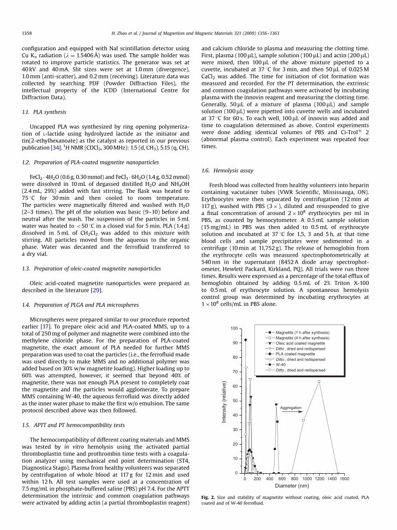
Fig. 2. Size and stability of magnetite without coating, oleic acid coated, PLA
coated and of W-40 ferrofluid.
H. Zhao et al. / Journal of Magnetism and Magnetic Materials 321 (2009) 1356–13631358
configuration and equipped with NaI scintillation detector usingCu Ka radiation (l ¼ 1.5406 A) was used. The sample holder wasrotated to improve particle statistics. The generator was set at40 kV and 40 mA. Slit sizes were set at 1.0 mm (divergence),1.0 mm (anti-scatter), and 0.2 mm (receiving). Literature data wascollected by searching PDF (Powder Diffraction Files), theintellectual property of the ICDD (International Centre forDiffraction Data).
1.1. PLA synthesis
Uncapped PLA was synthesized by ring opening polymeriza-tion of L-lactide using hydrolyzed lactide as the initiator andtin(2-ethylhexanoate) as the catalyst as reported in our previouspublication [34]. 1H NMR (CDCl3, 300 MHz): 1.5 (d, CH3), 5.15 (q, CH).
1.2. Preparation of PLA-coated magnetite nanoparticles
FeCl2 �4H2O (0.6 g, 0.30 mmol) and FeCl3 �6H2O (1.4 g, 0.52 mmol)were dissolved in 10 mL of degassed distilled H2O and NH4OH(2.4 mL, 29%) added with fast stirring. The flask was heated to75 1C for 30 min and then cooled to room temperature.The particles were magnetically filtered and washed with H2O(2–3 times). The pH of the solution was basic (9–10) before andneutral after the wash. The suspension of the particles in 5 mLwater was heated to o50 1C in a closed vial for 5 min. PLA (1.4 g)dissolved in 5 mL of CH2Cl2 was added to this mixture withstirring. All particles moved from the aqueous to the organicphase. Water was decanted and the ferrofluid transferred toa dry vial.
1.3. Preparation of oleic-coated magnetite nanoparticles
Oleic acid-coated magnetite nanoparticles were prepared asdescribed in the literature [29].
1.4. Preparation of PLGA and PLA microspheres
Microspheres were prepared similar to our procedure reportedearlier [17]. To prepare oleic acid and PLA-coated MMS, up to atotal of 250 mg of polymer and magnetite were combined into themethylene chloride phase. For the preparation of PLA-coatedmagnetite, the exact amount of PLA needed for further MMSpreparation was used to coat the particles (i.e., the ferrofluid madewas used directly to make MMS and no additional polymer wasadded based on 30% w/w magnetite loading). Higher loading up to60% was attempted, however, it seemed that beyond 40% ofmagnetite, there was not enough PLA present to completely coatthe magnetite and the particles would agglomerate. To prepareMMS containing W-40, the aqueous ferrofluid was directly addedas the inner water phase to make the first w/o emulsion. The sameprotocol described above was then followed.
1.5. APTT and PT hemocompatibility tests
The hemocompatibility of different coating materials and MMSwas tested by in vitro hemolysis using the activated partialthromboplastin time and prothrombin time tests with a coagula-tion analyzer using mechanical end point determination (ST4,Diagnostica Stago). Plasma from healthy volunteers was separatedby centrifugation of whole blood at 117 g for 12 min and usedwithin 12 h. All test samples were used at a concentration of7.5 mg/mL in phosphate-buffered saline (PBS) pH 7.4. For the APTTdetermination the intrinsic and common coagulation pathwayswere activated by adding actin (a partial thromboplastin reagent)
and calcium chloride to plasma and measuring the clotting time.First, plasma (100mL), sample solution (100mL) and actin (200mL)were mixed, then 100mL of the above mixture pipetted to acuvette, incubated at 37 1C for 3 min, and then 50mL of 0.025 MCaCl2 was added. The time for initiation of clot formation wasmeasured and recorded. For the PT determination, the extrinsicand common coagulation pathways were activated by incubatingplasma with the innovin reagent and measuring the clotting time.Generally, 50mL of a mixture of plasma (100mL) and samplesolution (100mL) were pipetted into cuvette wells and incubatedat 37 1C for 60 s. To each well, 100mL of innovin was added andtime to coagulation determined as above. Control experimentswere done adding identical volumes of PBS and Ci-Trols 2(abnormal plasma control). Each experiment was repeated fourtimes.
1.6. Hemolysis assay
Fresh blood was collected from healthy volunteers into heparincontaining vacutainer tubes (VWR Scientific, Mississauga, ON).Erythrocytes were then separated by centrifugation (12 min at117 g), washed with PBS (3� ), diluted and resuspended to givea final concentration of around 2�108 erythrocytes per ml inPBS, as counted by hemocytometer. A 0.5 mL sample solution(15 mg/mL) in PBS was then added to 0.5 mL of erythrocytesolution and incubated at 37 1C for 1.5, 3 and 5 h, at that timeblood cells and sample precipitates were sedimented in acentrifuge (10 min at 11,752 g). The release of hemoglobin fromthe erythrocyte cells was measured spectrophotometrically at540 nm in the supernatant (8452 A diode array spectrophot-ometer, Hewlett Packard, Kirkland, PQ). All trials were run threetimes. Results were expressed as a percentage of the total efflux ofhemoglobin obtained by adding 0.5 mL of 2% Triton X-100to 0.5 mL of erythrocyte solution. A spontaneous hemolysiscontrol group was determined by incubating erythrocytes at1�108 cells/mL in PBS alone.

ARTICLE IN PRESS
H. Zhao et al. / Journal of Magnetism and Magnetic Materials 321 (2009) 1356–1363 1359
2. Results and discussion
Uncapped PLA was successfully used to coat magnetiteparticles, which made them lipophilic and readily dispersablein organic solvents such as CH2Cl2. Using of commercial PLA(e.g., Resomer L104) did not provide a suitable coating for the
Fig. 3. SEM pictures of microspheres (on the left) and their corresponding size distribut
loading; (C) W-40-formulated PLGA MMS, 51.20% magnetite loading; and (D) oleic acid
magnetic particles as PLA is usually capped (esterified with shortcarbon chains) to increase the shelf life of the polymer. TEMimages of magnetite nanoparticles (Fig. 1) showed that all thetested coating materials were able to separate the single-magnetite crystals from each other (Fig. 1B–D). Uncoatedmagnetite, however, agglomerated due to their high surface
0
2
4
6
8
10
12
14
Freq
uenc
y (%
)
02468
101214161820
Freq
uenc
y (%
)
05
1015202530354045
Freq
uenc
y (%
)
0
5
10
15
20
25
30
35
Freq
uenc
y (%
)
Size (μm)0.0 0.2 0.4 0.6 0.8 1.0 1.2 1.4 1.6 1.8 2.0 2.2 2.4 2.6 2.8 3.0
Size (μm)0.0 0.2 0.4 0.6 0.8 1.0 1.2 1.4 1.6 1.8 2.0 2.2 2.4 2.6 2.8 3.0
Size (μm)0.0 0.2 0.4 0.6 0.8 1.0 1.2 1.4 1.6 1.8 2.0 2.2 2.4 2.6 2.8 3.0
Size (μm)0.0 0.2 0.4 0.6 0.8 1.0 1.2 1.4 1.6 1.8 2.0 2.2 2.4 2.6 2.8 3.0
ion (on the right). (A) PLGA microspheres; (B) PLA-coated MMS, 28.81% magnetite
-coated PLGA MMS, 20.84% magnetite loading.

ARTICLE IN PRESS
H. Zhao et al. / Journal of Magnetism and Magnetic Materials 321 (2009) 1356–13631360
energy of the nanoparticles (Fig. 1A). The measurement of theparticles’ size distribution (Fig. 2) confirmed these observations.Without a coating agent, magnetite nanoparticles clumpedtogether, and grew within 4 h to agglomerates of more than1mm in size. Such agglomerates cannot be dispersed anymore, noteven by ultrasound treatment. For all 3 types of the coatednanoparticles, however, even drying and redispersion severalweeks later resulted in unaltered size distributions and thus goodsize stability (Fig. 2).
As shown experimentally, uncoated magnetite nanoparticleshave a large surface area-to-volume ratio, which gives them thetendency to increase in particle size due to agglomeration andlarge cluster formation, which in turn can show strong magneticdipole–dipole attraction and ferromagnetic behavior [35].For effective stabilization of iron oxide nanoparticles, a highcoating density is thus desirable. Potential stabilizing agentsinclude polymers (e.g., PEG/PAA [17]), various long-chaincarboxylic acids, phosphonates and phosphates [36]. Alkylphosphonates and phosphates yield more thermodynamicallystable dispersions of magnetite nanoparticles than oleic acid atphysiological pH and might thus be preferred [36].
The preparation of MMS with native and coated magnetite bydouble emulsion–solvent extraction yielded MMS of around 1mmin size, as shown by SEM pictures and corresponding sizedistributions (Fig. 3). All MMS were spherical, and with theexception of the W-40 formulated ones (Fig. 3C), they all showedsmooth surfaces.
0
20
40
60
80
100
Wei
ght (
%)
Temperature (°C)
Tem
Oleic acid PLA
0
20
40
60
80
100
Wei
ght (
%)
MMS, PLA coate MMS, W-40 MMS, oleic acid
0 100 200
0 100 200 300 400 500
Fig. 4. TGA results. (A) Oleic acid and PLA; (B) magnetite; and (C) PLA-coated MMS (28.
formulated MMS (63.07% magnetite loading).
2.1. Characteristics of iron oxide nanoparticles and MMS
While the organic substances, oleic acid and PLA showed acomplete weight loss in TGA in a single step when being heatedfrom 25 to 550 1C (Fig. 4A and C), native magnetite showed anoverall weight gain of 2.576% (Fig. 4B). In addition, the color of thematerial changed from black to red that was due to completeoxidation of magnetite according to the overall scheme of
2Fe3O4 þ 0:5O2 ! 3Fe2O3 (2)
Theoretically, the molecular weight should have increased by3.455%. The difference between the observed and theoreticalweight increment was likely due to the original starting sampleconsisting not only of magnetite, but also some maghemite(g-Fe2O3). A mixture of 74.56% magnetite and 25.44% ofmaghemite in the original sample would lead to a calculated2.576% of weight increment. An analysis of the original sample byX-ray diffraction before and after TGA (Fig. 5) revealed thishypothesis to be very likely. The major diffraction peakscould be assigned to related reflection lines and were in goodagreement with the literature values for magnetite [37](PDF#01-089-0691), maghemite [38] (PDF#01-089-5892) andhematite [39] (PDF#01-089-0596). Initially, the diffraction patternof the particles showed the characteristics of magnetite ormaghemite—it is impossible to separate the two based only ontheir diffraction pattern. After TGA in air, however, there was a
Temperature (°C)
perature (°C)
99.5
100.0
100.5
101.0
101.5
102.0
102.5
Magnetite
Wei
ght (
%)
d
coated
63.07%
28.81%
20.84%
0 100 200 300 400 500
300 400 500
81% magnetite loading); oleic acid-coated MMS (20.84% magnetite loading); W-40-

ARTICLE IN PRESS
20
40
60
t (em
u/g)
Magnetite
MMS (W-40), 60%
MMS (PLA coated)
H. Zhao et al. / Journal of Magnetism and Magnetic Materials 321 (2009) 1356–1363 1361
clear transformation of magnetite to hematite (a-Fe2O3), as hasbeen reported before [40].
Based on TGA, the final iron oxide content of the MMS was20.84% for oleic acid-coated MMS, 28.81% for PLA-coated MMSand 63.07% for the W-40 ferrofluid encapsulated MMS batches,respectively. The calculated encapsulation efficiencies were thus40%, 83% and 96%, respectively. Encapsulating magnetite from theinner water phase yielded the highest loading efficiencies.
All MMS exhibited the typical superparamagnetic behavior ofzero coercivity and no remanence in their magnetization curvesmeasured at room temperature (Fig. 6). This was even true forthe native, uncoated magnetite, whose aggregate size was above1000 nm (Fig. 1B). The aggregates, thus, still consist of singleparticles with a saturation magnetization of 58.5 emu/g. MMSloaded with 63.07% iron oxide from W-40 exhibited a saturationmagnetization of 37.8 emu/g. MMS loaded with 28.81% iron oxidecoated by PLA showed a magnetization of 19.2 emu/g, while MMSloaded with 20.84% magnetite coated by oleic acid showed one of12.9 emu/g. The measured saturation magnetizations are within5.5% of the theoretical values expected from the TGA measure-ments.
-1.0 -0.5 0.0 0.5 1.0
-60
-40
-20
0
Mag
netic
mom
en
Magnetic field strength (T)
MMS (oleic acid coated)
Fig. 6. Vibrating sample magnetometer (VSM) results of different MMS.
2.2. APTT and PT determination
For in vivo clinical applications the MMS will be in contact withblood; therefore, their effect on the induction of (unwanted) bloodclotting had to be investigated. The blood coagulation cascadeincludes intrinsic and extrinsic pathways that were evaluated byAPTT and PT studies, respectively. As shown by the white bars inFig. 7, none of the MMS or control substances prolonged the timeuntil normal fibrin clot formation with the PT assay. The extrinsicpathway of coagulation is thus not affected at all by MMS andcoating materials. The evaluation of the intrinsic pathway byAPTT, however, showed that some samples prolonged bleedingtimes (grey bars in Fig. 7). Compared to the PBS control,PLA-coated magnetite microspheres, oleic acid-coated magnetitemicrospheres and W-40 prolonged APTT significantly (Po0.001),
20 30 40 50 60 700
20
40
60
80
Inte
nsity
2θ
Fig. 5. Powder X-ray diffraction spectra of PLA-coated particles before (bottom)
and after (middle) TGA along with references (top) for magnetite (’), maghemite
(m), and hematite (� ). The arrows show appearance of new signals characteristic
of hematite.
although none of the values reached the intermediate elevated(abnormal) range of the Dade Ci-Trols coagulation control (Fig. 7).Many foreign materials show such a change of plasma coagulationproperties, as for example different polymers [41], hydrogels [42]and Nitinol devices [43]. Changes in coagulation properties mightlead to thrombosis, although at least one paper describes thatusing APTT results should only be used as an indication ofbiomaterial induced coagulation activity, not as absolute results[41]. Some studies have concluded that activation of contactsystem started by interaction of negative-charged surfaces withplasma [44]. The possible presence of carboxylate groups at the
PBS
Oleicac
idW
-40
PLGA M
S
MMS, PLA
coate
d, 28
%
MMS, W-40
, 60%
MMS, oleic
acid
coate
d, 20
%
Positiv
e con
trol
0
10
20
30
40
50
60
70
80
**
*
Coa
gula
tion
time
(sec
)
APTT
PT
Fig. 7. APTT and PT hemocompatibility results. The positive control is the
intermediate elevated (abnormal) range of the Dade Ci-Trols coagulation control
agent. * Po0.001.
ARTICLE IN PRESS
H. Zhao et al. / Journal of Magnetism and Magnetic Materials 321 (2009) 1356–13631362
PLA MMS surface, which at physiological pH would be negativelycharged, might be the reason behind prolonged APTT times.If necessary, this could be prevented by optimizing the amount ofcarboxylated PLA during magnetite coating and adding cappedPLA as matrix material during the MMS preparation.
2.3. In vitro hemolysis analysis
Any substances to be used in parenteral formulations must betested for potential incompatibility with red blood cells [45].
0
20
40
60
80
100 PBS
7.5 mg/ml
1.5 mg/ml
0.3 mg/ml
0.06 mg/ml
Hem
olys
is (%
)
Hemolysis time (hr)0 1 2 3 4 5
0
20
40
60
80
100
Hem
olys
is (%
)
Hemolysis time (h)
0
20
40
60
80
100
Hem
olys
is (%
)
Hemolysis time (h)
0 1 2 3 4 5
0 1 2 3 4 5
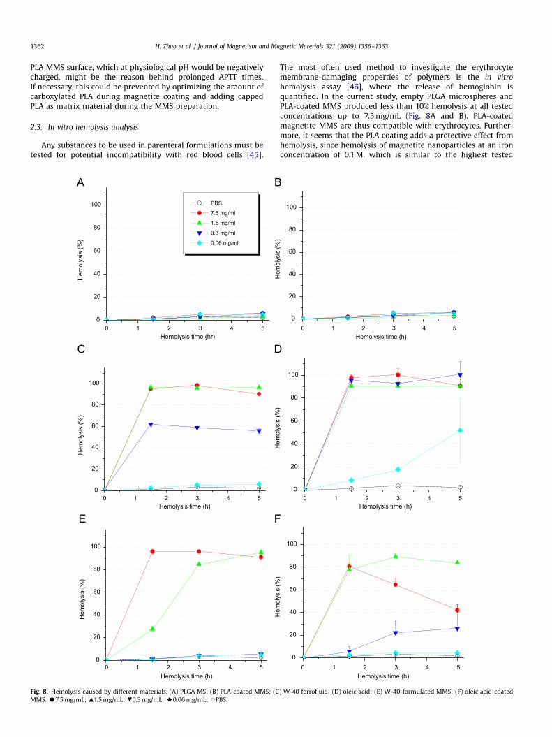
Fig. 8. Hemolysis caused by different materials. (A) PLGA MS; (B) PLA-coated MMS; (C
MMS. K7.5 mg/mL; m1.5 mg/mL; .0.3 mg/mL; E0.06 mg/mL; JPBS.
The most often used method to investigate the erythrocytemembrane-damaging properties of polymers is the in vitro
hemolysis assay [46], where the release of hemoglobin isquantified. In the current study, empty PLGA microspheres andPLA-coated MMS produced less than 10% hemolysis at all testedconcentrations up to 7.5 mg/mL (Fig. 8A and B). PLA-coatedmagnetite MMS are thus compatible with erythrocytes. Further-more, it seems that the PLA coating adds a protective effect fromhemolysis, since hemolysis of magnetite nanoparticles at an ironconcentration of 0.1 M, which is similar to the highest tested
0
20
40
60
80
100
Hem
olys
is (%
)
Hemolysis time (h)0 1 2 3 4 5
0
20
40
60
80
100
Hem
olys
is (%
)
Hemolysis time (h)
0
20
40
60
80
100
Hem
olys
is (%
)
Hemolysis time (h)0 1 2 3 4 5
0 1 2 3 4 5
) W-40 ferrofluid; (D) oleic acid; (E) W-40-formulated MMS; (F) oleic acid-coated

ARTICLE IN PRESS
H. Zhao et al. / Journal of Magnetism and Magnetic Materials 321 (2009) 1356–1363 1363
concentration here, has been reported to be significant [47]. Theother test samples, W-40 ferrofluid and oleic acid-coatedmagnetic particles induced hemolysis of erythrocytes at concen-trations as low as 0.3 and 0.06 mg/mL, whereas hemolysis wascomplete (100%) at 1.5 mg/mL for W-40 and 0.3 mg/mL for oleicacid (Fig. 8C and D).
Hemolysis is both concentration and time dependent, asshown in Fig. 8E and F. W-40 MMS used in concentrations of0.3 mg/mL or oleic acid-coated MMS in concentrations of less than0.06 mg/mL are hemocompatible (less than 5% hemolysis), whilehigher concentrations lead to hemolysis, very likely due to thenature of coating and the stabilizer’s surfactant activity. It istherefore appropriate for in vivo applications to early add-onhemocompatibility studies to other toxicity studies such as theMTT assay.
Despite these findings, oleic acid is widely used as a stabilizeror coating material for magnetite nanoparticles [20,29,48],designed for in vivo targeted delivery applications after vascularinjection [49]. In general, oleic acid has been considered arelatively non-toxic coating material. Magnetite nanoparticlescoated by oleic acid at total blood volume concentrations of 4% inrats, however, showed significant side effects, such as diarrhea,tachycardia, tachypnea, seizure, crowing position, clonic convul-sion and immediate shock [21].
W-40 ferrofluids with low loading concentrations of about 5%have been encapsulated in nanoparticles [26,27] and successfullyused as an MRI contrast agent in the kidney of rabbits [27]. Oleicacid and sodium dodecylbenzenesulfonate used as magnetitestabilizers can thus induce significant hemolysis even at ratherlow concentrations. MMS made from magnetite nanoparticlescoated with these materials can produce hemolytic effects, whichmight be a serious barrier for further in vivo applications.Hemocompatibility tests of MMS should thus be a part of thebiocompatibility testing of microspheres early on. Although APTT,PT and hemolysis tests may give a good indication of potentialtoxicity, only the actual clinical evaluation will be able to pinpointthe relevance and importance of these findings.
Therefore, use of uncapped PLA as a coating material formagnetite in order to make biodegradable MMS serves a dualpurpose. It can not only be used as the matrix material for thepreparation of MMS; but also as a lipophilic stabilizer. Its knownbiocompatibility has been confirmed, and its hemocompatibilityis excellent at all tested concentrations. The highest concentrationof 7.5 mg/mL was chosen to be appropriate for clinical drugdelivery applications. From our results, both PLA and PLGAshowed excellent hemocompatibility with red blood cells. There-fore, similarly-uncapped PLGA can be used to coat the magneticparticles. Important for the use of both polymers is the fact thatthey have free carboxylate groups. Most commercially availablepolymers are capped at both ends to increase shelf life of thematerial, and are not useful for magnetite coating as there is noanchoring possible to the surface of the magnetite.
Acknowledgements
Kelly Gilmour is acknowledged for the magnetic measure-ments. We appreciate funding by the Canadian Institutes of
Health Research (CIHR) Grant MOP-74597 and the NaturalSciences and Engineering Research Council of Canada (NSERC)discovery grant.
References
[1] U.O. Hafeli, in: R. Arshady, K. Kono (Eds.), Smart Nanoparticles inNanomedicine—the MML Series, Vol. 8, Kentus Books, London, UK, 2006,p. 77.
[2] I. Hilger, F. Hofmann, J.R. Reichenbach, et al., Rofo. Fortschr. Geb. Rontgenstr.Neuen Bildgeb. Verfahr. 174 (2002) 101.
[3] Z. Berkova, J. Kriz, P. Girman, et al., Transplant. Proc. 37 (2005) 3496.[4] L.L. Muldoon, M. Sandor, K.E. Pinkston, et al., Neurosurgery 57 (2005) 785.[5] M. Radisic, R.K. Iyer, S.M. Murthy, Int. J. Nanomed. 1 (2006) 3.[6] D.C.F. Chan, D.B. Kirpotin, P.A. Bunn, J. Magn. Magn. Mater. 122 (1993) 374.[7] C. Plank, F. Scherer, U. Schillinger, et al., J. Liposome Res. 13 (2003) 29.[8] C.C. Chu, in: D.F. Williams (Ed.), CRC Critical Reviews in Biocompatibility, Vol.
1, CRC Press, Boca Raton, 1985, p. 261.[9] J.L. Cleland, in: Sanders, Hendren (Eds.), Protein Delivery: Physical Systems,
Plenum Press, New York, 1997, p. 1.[10] U. Schwertmann, R.M. Cornell, Iron Oxides in the Laboratory: Preparation and
Characterization, first ed., Weinheim, New York, 1991.[11] Y.X. Wang, S.M. Hussain, G.P. Krestin, Eur. Radiol. 11 (2001) 2319.[12] L.X. Tiefenauer, in: T. Vo-Dinh (Ed.), Nanotechnology in Biology and Medicine:
Methods, Devices, and Applications, Vol. Section D Nanomedicine Applica-tions D1, CRC Press, Taylor and Francis, Boca Raton, FL, USA, 2007, p. 1.
[13] Y. Sahoo, A. Goodarzi, M.T. Swihart, et al., J. Phys. Chem. B Condens. MatterMater. Surf. Interfaces Biophys. 109 (2005) 3879.
[14] J. Park, E. Lee, N.M. Hwang, et al., Angew. Chem. Int. Ed. Engl. 44 (2005) 2872.[15] W.C. Elmore, Phys. Rev. 54 (1938) 309.[16] R. Massart, Patent no. 4,329,241 (US), May 11.[17] H. Zhao, J. Gagnon, U.O. Hafeli, Biomagn. Res. Technol. 5 (2007) 2.[18] S. Levine, Science 123 (1956) 185.[19] N. Fauconnier, A. Bee, J. Roger, et al., Prog. Colloid Polym. Sci. 100 (1996) 212.[20] Z. Wang, H. Guo, Y. Yu, et al., J. Magn. Magn. Mater. 302 (2006) 397.[21] S.I. Park, J.H. Lim, J.H. Kim, et al., Phys. Status Solidi (b) 241 (2004) 1662.[22] D.G. Duguay, Ph.D. Thesis, McGill, 1991.[23] I.J. Oh, J.Y. Oh, K.C. Lee, Arch. Pharm. Res. 16 (1993) 312.[24] U.O. Hafeli, S.M. Sweeney, B.S. Beresford, et al., J. Biomed. Mater. Res. 28
(1994) 901.[25] S.K. Kraeft, U.O. Hafeli, L.B. Chen, in: U. Hafeli, W. Schutt, J. Teller, et al. (Eds.),
Scientific and Clinical Applications of Magnetic Carriers, Plenum, New York,1997, p. 149.
[26] S.J. Lee, J.R. Jeong, S.C. Shin, et al., Colloids Surfaces A: Physicochemical Eng.Aspects 255 (2005) 19.
[27] S.J. Lee, J.R. Jeong, S.C. Shin, et al., J. Magn. Magn. Mater. 272–276 (2004) 2432.[28] K. Murakami, T. Kinouchi, H. Matsumoto, et al., Tokushima J. Exp. Med. 43
(1996) 47.[29] X. Liu, M.D. Kaminski, Y. Guan, et al., J. Magn. Magn. Mater. 306 (2006) 248.[30] M.A. Morales, T.K. Jain, V. Labhasetwar, et al., J. Appl. Phys. 97 (2005) 10Q905.[31] J. Sun, S. Zhou, P. Hou, et al., J. Biomed. Mater. Res. A 80 (2007) 333.[32] Y.C. Fung, Biomechanics: Circulation, second ed., Springer, New York, 1997.[33] M.D. Abramoff, P.J. Magelhaes, S.J. Ram, Biophotonics Int. 7 (2004) 36.[34] K. Saatchi, U.O. Hafeli, Dalton Trans. 39 (2007) 4439.[35] A.K. Gupta, M. Gupta, Biomaterials 26 (2005) 3995.[36] Y. Sahoo, H. Pizem, T. Fried, et al., Langmuir 17 (2001) 7907.[37] H. Fjellvag, F. Gronvold, S. Stolen, et al., J. Solid State Chem. 124 (1996) 52.[38] H.-S. Shin, Yoop Hakhoechi 35 (1998) 1113.[39] V.A. Sadykov, L.A. Isupova, S.V. Tsybulya, et al., J. Solid State Chem. 123 (1996)
191.[40] R.M. Cornell, U. Schwertmann, The Iron Oxides: Structure, Properties,
Reactions, Occurrences and Uses, VCH, Weinheim, 1996.[41] R.K. Kainthan, S.R. Hester, E. Levin, et al., Biomaterials 28 (2007) 4581.[42] L.P. Amarnath, A. Srinivas, A. Ramamurthi, Biomaterials 27 (2006) 1416.[43] X. Kong, R.G. Grabitza, W.V. Oeverenb, et al., Biomaterials 23 (2002) 1775.[44] A.P. Kaplan, M. Silverberg, Blood 70 (1987) 1.[45] D. Shim, D.S. Wechsler, T.R. Lloyd, et al., Cathet. Cardiovasc. Diagn. 39 (2007)
287.[46] D. Fischer, Y. Li, B. Ahlemeyer, et al., Biomaterials 24 (2003) 1121.[47] F.Y. Cheng, C.H. Su, Y.S. Yang, et al., Biomaterials 26 (2005) 729.[48] V.V. Korolev, A.G. Ramazanova, A.V. Blinov, Russ. Chem. Bull. 51 (2002)
2044.[49] X.Q. Liu, M.D. Kaminski, J.S. Riffle, et al., J. Magn. Magn. Mater. 311 (2007) 84.