preparation and optical characterisation of antireflection coatings
TRANSCRIPT

Comprehensive Summaries of Uppsala Dissertationsfrom the Faculty of Science and Technology 562
_____________________________ _____________________________
Preparation and Optical Characterisationof Antireflection Coatings and Reflector
Materials for Solar Energy SystemsBY
PER NOSTELL
ACTA UNIVERSITATIS UPSALIENSISUPPSALA 2000

2
Dissertation for the Degree of Doctor of Philosophy in Solid State Physics presented atUppsala University in 2000
ABSTRACT
Nostell P., 2000. Preparation and optical characterisation of antireflection coatings andreflector materials for solar energy systems. Acta Universitatis Upsaliensis. ComprehensiveSummaries of Uppsala Dissertations frrom the Faculty of Science and Technology 562. 68pp. Uppsala ISBN 91-554-4794-5
An angle-resolved scatterometer and an integrating sphere for reflectance measurements atoblique angles of incidence have been designed and evaluated. The integrating sphere has acentre-mounted sample holder and the detector sits at the end of the sample holder andtherefore always faces the same sphere wall area. The sphere geometry plays an importantrole for the modelling of detected signals and the reflected intensity has to be divided into aspecular and a diffuse component. These components must be treated separately in themodelling. These two instruments, as well as traditional spectrophotometers, have been usedfor the evaluation of solar energy materials. Scattering as well as non-scattering surfaceshave been studied, requiring different measurement techniques.
By using angle-resolved scatterometry it has been demonstrated that a solar reflector doesnot need to be perfectly specular provided the concentration factor is low. Thus it is possibleto use inexpensive aluminium foil as the reflector material. The possibility of increasing thereflectance of aluminium with thin dielectric films of silicon and titanium oxides for pv-celland solar thermal collector application has been investigated. Particular attention has beenpaid to the angular optical properties since thin films strongly affect them owing tointerference effects. In an under-glazing application for pv-cells, the use of aluminiumcoated with titania and silica is recommended. The long-term stability of several reflectormaterials has been studied and anodised aluminium protected by a UV-stabilised polymercoating is recommended for solar collector reflectors.
Antireflective films consisting of porous silicon oxide for solar collector cover glazings havebeen studied. The films were prepared by a dip-coating process using a suspension ofnano-sized silicon oxide particles. This treatment increased the solar transmittance by 5.5percentage points. It has also been shown that it is possible to temper antireflection treatedglazings without seriously affecting the optical performance. The tempering also stronglyimproves the mechanical stability of the film.
Some of the measurements presented in this thesis were used as input data to simulationprograms, which calculate the collected annual energy as a function of the optical propertiesof the different components. It was found that spectrophotometric laboratory measurementsagree well with outdoor collector testings.
Per Nostell, Department of Materials Science, The Ångström Laboratory, UppsalaUniversity, Box 534, SE-751 21 Uppsala, Sweden
© Per Nostell 2000
ISSN 1104-232X
ISBN 91-554-4794-5
Printed in Sweden by Lindbergs Grafiska, Uppsala 2000

3
Du mußt herrschen und gewinnenoder dienen und verlieren.Leiden oder triumphierenAmboss oder Hammer sein.
-Goethe

4
List of publications
I Antireflection of glazings for solar energy applications
P. Nostell, A. Roos and B. Karlsson, Sol. Energy Mat. Sol. Cells, 54, (1998) pp.
223-233
II Optical and mechanical properties of sol-gel antireflective films for solar
energy applications
P. Nostell, A. Roos and B. Karlsson. Thin Solid Films, 351 (1999) pp. 170-175
III Single-beam integrating sphere spectrophotometer for reflectance and
transmittance measurements versus angle of incidence in the solar
wavelength range on diffuse and specular samples
P. Nostell, A. Roos and D. Rönnow, Rev. Sci. Instr., 70 (1999), pp. 2481-2494
IV Optical characterisation of solar reflecting surfaces
P. Nostell, A. Roos and B. Karlsson, Proc. SPIE, paper 3138-20 (1997), pp. 163-
172, San Diego U.S.A.
V Ageing of solar booster reflector materials
P. Nostell, A. Roos and B. Karlsson, Sol. Energy Mat. Sol. Cells, 54, (1998) pp.
235-246
VI Optical scattering from rough rolled aluminium surfaces
M. Rönnelid, M. Adsten, T. Lindström, P. Nostell and E. Wäckelgård, submitted to
Appl. Opt.
VII Optical efficiency of a PV-thermal hybrid CPC module
M. Brogren, P. Nostell and B. Karlsson, submitted to Solar Energy
VIII The impact of the optical and thermal properties on the performance of flat
plate solar collectors
B. Hellström, M. Adsten, P. Nostell, E. Wäckelgård and B. Karlsson, submitted to
Solar Energy
IX Angular dependent optical properties from outdoor measurements of
solar glazings
A. Helgesson, P. Nostell and B. Karlsson, submitted to Solar Energy

5
X Interference enhancement of the oblique incidence reflectance of aluminum
reflectors for solar thermal and photovoltaic applications
P. Nostell, in manuscript
Comments on my participation
I, II All experimental work including sample preparation, most of the
writing
III All optical measurements, most of the writing, all calculations
IV, V All optical measurements, no sample preparation, most of the writing
VI Most optical measurements, part of the writing
VII, VIII, IX All spectrophotometric measurements, part of the writing
X No co-authors
Publications not included in the thesis
I Durability testing of antireflection coatings for solar applications
G. Jorgensen, S. Brunold, M. Köhl, P. Nostell, H. Oversloot and A. Roos, Proc.
SPIE 3789 (1999) Denver, USA
II Gigantic resistivity and band gap changes in GdOyHx thin films
A. Miniotas, B. Hjörvarsson, L. Douysset and P. Nostell, Appl. Phys. Lett., 76
(2000)
III Antireflection treatment of glazings with an improved silica sol-gel process
P. Nostell, A. Roos and B. Karlsson, Proc. North Sun '97 (1997) Espoo-Otaniemi,
Finland
IV Mechanical and optical properties of AlOyHx thin films
J. Snyder, B. Hjörvarsson, P. Nostell, J. Jonsson, J. Lu, in manuscript

6
TABLE OF CONTENTS
1 INTRODUCTION . . . . . . . . . . . . . . . . . . . . . . . . . . . . . . . . . . . . . . . . . . . . . . . . . . . . . . . . . . . . . . . . . . . . . . . . . . . . . . 7
2 SOLAR ENERGY. . . . . . . . . . . . . . . . . . . . . . . . . . . . . . . . . . . . . . . . . . . . . . . . . . . . . . . . . . . . . . . . . . . . . . . . . . . . . . 9
3 OPTICAL CHARACTERISATION TECHNIQUES . . . . . . . . . . . . . . . . . . . . . . . . . . . . . . . . . . . . . 1 4
3.1 SMOOTH SAMPLES ................................................................................................... 15
3.2 SCATTERING SAMPLES.............................................................................................. 17
3.2.1 Transmittance integrating sphere ...................................................................... 18
3.2.2 Reflectance integrating sphere.......................................................................... 20
3.2.3 Angle-resolved scatterometer........................................................................... 23
3.3 DOUBLE- AND SINGLE-BEAM INSTRUMENTS .................................................................. 25
3.4 ANGULAR OPTICAL PROPERTIES OF SCATTERING SOLAR COLLECTING DEVICES...................... 26
4 OPTICAL MODELLING. . . . . . . . . . . . . . . . . . . . . . . . . . . . . . . . . . . . . . . . . . . . . . . . . . . . . . . . . . . . . . . . . . . . . 2 9
5 ALUMINIUM REFLECTORS . . . . . . . . . . . . . . . . . . . . . . . . . . . . . . . . . . . . . . . . . . . . . . . . . . . . . . . . . . . . . . 3 2
5.1 OPTICAL PROPERTIES OF REFLECTORS........................................................................... 33
5.2 REFLECTOR MATERIALS............................................................................................ 34
5.2.1 Angular properties of reflector materials............................................................ 36
5.2.2 Scattering properties of reflectors..................................................................... 37
5.2.3 Angular thin film design and properties............................................................... 38
6 SINGLE FILM ANTIREFLECTIVE COATINGS. . . . . . . . . . . . . . . . . . . . . . . . . . . . . . . . . . . . . . . . 4 4
6.1 HISTORICAL NOTES AND BACKGROUND........................................................................ 46
6.2 FILM PREPARATION AND OPTICAL PROPERTIES OF ANTIREFLECTIVE COATINGS ..................... 48
6.3 MECHANICAL PROPERTIES OF ANTIREFLECTIVE FILMS ..................................................... 52
7 OPTICAL PROPERTIES AND SYSTEM PERFORMANCE. . . . . . . . . . . . . . . . . . . . . . . . . . 5 5
7.1 GLAZINGS AND REFLECTORS FOR SOLAR COLLECTORS ..................................................... 55
7.2 REFLECTORS AND GLAZINGS FOR PV/T-HYBRIDS............................................................. 58
8 SUMMARY AND CONCLUSIONS. . . . . . . . . . . . . . . . . . . . . . . . . . . . . . . . . . . . . . . . . . . . . . . . . . . . . . . . 6 1
ACKNOWLEDGEMENTS . . . . . . . . . . . . . . . . . . . . . . . . . . . . . . . . . . . . . . . . . . . . . . . . . . . . . . . . . . . . . . . . . . . . . . . . . 6 2
REFERENCES . . . . . . . . . . . . . . . . . . . . . . . . . . . . . . . . . . . . . . . . . . . . . . . . . . . . . . . . . . . . . . . . . . . . . . . . . . . . . . . . . . . . . . 6 4

7
1 INTRODUCTION
The existence of mankind is only due to the fact that the earth receives solar irradiation in
moderate proportions. This irradiation is converted into a number of different energy forms
that can be useful to different degrees. The only energy source used by man that does not
stem from the sun's irradiation is the energy produced in nuclear power plants. All other
forms of energy have the sun as their source.
All energy sources have advantages and disadvantages. Today, new energy sources are
being sought since several energy production technologies suffer from serious problems.
As yet the storage of nuclear waste has not been resolved and the burning of coal and oil
leads to emissions of carbon dioxide, which is a strong greenhouse gas[1]. Another
problem with using fossil material is the emission of sulfur and nitride oxides, which are
converted into acids in the atmosphere and are eventually precipitated as acid rain. It is,
however, economic reasons that have biased the search for new energy sources. In the
middle of the seventies oil prices virtually exploded and the development of alternative
energy sources hitherto and energy politics are children of this crisis.
The highest conversion efficiency factor for energy production is man-made solar collecting
devices that absorb irradiation and convert it into useful energy. One device type converts
solar irradiation into electricity, photo-voltaic cells, or pv-cells[2]. These are semiconductors
and by a quantum conversion process they directly convert solar irradiation into electricity.
The other solar collecting type is the photo-thermal converter[3], usually called solar
collector. These convert irradiation into heat at lower temperatures, <300 °C, or into
electricity by powering a turbine with steam at higher temperatures. A mix of these two solar
collecting devices also exists, pv/thermal hybrid, which converts excessive heat in a pv-cell
into hot water at low temperatures, <60 °C.
Solar energy collected by man-made collectors is not always easy to use since the variation
in received solar irradiation over the year is high, in particular at high latitudes, such as
Sweden[4]. Most energy is obtained during the summer when the energy demand is lowest.
A solution would be to store the energy produced in the summer[5] and use it in the winter
when the energy consumption is considerably higher. Furthermore, the power per unit area
is low which means that large area systems are required for high power plants.
Consequently, the material costs are high for solar collectors. Several high-performance
solar energy materials have already been developed, and even though there are still

8
performance improvements to be made, cost reduction is the key issue when it comes to
making collectors competitive with other energy sources.
In this thesis two kinds of solar energy materials have been studied, reflector materials,
which are used to reflect as much as possible of useful solar irradiation onto collectors and
antireflection coatings for cover glazings, which decrease the reflection losses of the
glazings. Both material categories should be as inexpensive as possible and therefore both
the manufacturing process and the material costs should be kept low. Furthermore, the
materials should exhibit long term stability since they must withstand more than 20 years of
outdoor exposure. In particular, optical measurements have been a widely used tool to
evaluate the studied materials. The optical properties of the materials put an upper limit to
their function and small variations can be detected. In favourable cases this permits
identification of the aging mechanisms and optical characterisation becomes a tool to
improve the materials. The influence of the material optical properties of antireflective
treated glazings and of booster reflectors on a solar collecting device has also been studied.
An angle-resolved scatterometer and an integrating sphere for the measurement of
reflectance at different angles of incidence of scattering materials have been designed and
evaluated within the course of this work. The reason for this is that angular optical
properties are of particular interest in this field of research since the solar energy is usually
received at an oblique angle of incidence.

9
2 SOLAR ENERGY
Spectral selectivity is a key issue in solar energy applications since frequently it is desirable
to have one of the optical quantities (R, T, or A) be zero in one wavelength interval and unity
in another. By solar energy materials we mean materials whose optical properties are
tailored in one way or another with respect to the sun's spectrum[6]. In Fig. 1 a solar
spectrum (ISO AM 1.5), the eye's luminous sensitivity, and the internal quantum efficiency
of silicon are displayed. For solar collecting devices, Planck's black body irradiation
spectrum [3] is of great importance, since it, together with the optical properties of the
material being studied, describes the reradiated heat. This quantity is called the thermal
emittance. For solar collectors the thermal emittance should be as low as possible to
decrease the thermal losses. In contrast to this, a pv-cell should have as high a thermal
emittance as possible to decrease its temperature. High temperatures reduce the efficiency of
pv-cells. Antireflective coatings reduce, as the name indicates, the reflectance of a surface,
and booster reflectors should have as high reflectance as possible. Therefore, both
antireflective coatings and booster reflectors are key issues in solar energy applications.
0
0.2
0.4
0.6
0.8
1
0
0.2
0.4
0.6
0.8
1
1.2
0.4 0.6 0.8 1 3
Eye Si Sun
Sen
siti
vity
Irradiance (Wm
-2µm
-1)
Wavelength (µm)
Fig. 1 Solar spectrum (ISO AM 1.5), eye's luminous sensitivity (Eye), and wavelengthdependent internal quantum conversion efficiency of crystalline silicon (Si).
Depending on the optical properties of the underlying structure, the transmittance and/or the
abstorptance is increased upon antireflection treatment. The inherent optical properties of a
single antireflective film are, however, not spectrally selective in the sense that the
transmittance or reflectance should be unity in one wavelength range and zero in another.
Although it is possible to design almost any spectral profile by means of thin dielectric

10
stacks, it is not frequently used in solar energy applications due to the high production costs
of such devices.
External reflectors might be used in three principal concentrating situations, which are
depicted in Fig. 2. The cover glazings and the solar absorbing units are also indicated in the
same figure. The concentration of solar irradiation with compound parabolic concentrators
(CPC) [4] and planar booster reflectors [5] at high latitudes have been extensively studied.
The requirements on the optical properties of the reflector become increasingly more
important from left to right in Fig. 2 since the concentration factor is increasing and the
system performance becomes more dependent on the reflector's optical performance.
Glazing
Reflector
Solar absorbing unit
Fig. 2 Principal drawing of three different solar absorber devices with reflectors. Theposition of the glazing is also indicated. The first to the left corresponds to a solar collectordevice with a planar booster reflector, the second to a truncated CPC, and the third to aparabolic reflector.
The absorbing unit in Fig. 2 might be either an absorber for photo-thermal conversion or a
pv-cell for electricity generation. In particular, the absorber is vulnerable and must be
protected from the degrading outdoor environment. This is achieved with a cover glazing,
which in solar energy applications is made of tempered low-iron glass or sometimes a UV-
stable plastic. Apart from protection purposes the glazing is also used for thermal insulation
purposes for thermal solar collectors. Two materials exhibit high reflectance throughout the
entire wavelength interval of the solar spectrum; aluminium and silver. Most reflectors are
made of these two materials. Another material candidate is stainless steel. The reflectance is
not as high as for the two other materials, but it is highly resistant to mechanical wear and
chemically it is very inert and it is therefore long-term stable.
For the optimisation of components for solar energy applications, it is necessary to study
the spectrum for which the actual component should be tailored. For the optical
performance in a certain application, however, it is convenient with a single number that

11
characterises the component. A reflector for solar thermal collectors for example should
have as high as possible a reflectance throughout the entire wavelength range of the solar
spectrum, cf. Fig. 1. It is, however, much more important that the reflectance is high at
0.55 µm, where the irradiated power is highest. This means that the solar spectrum should
be considered as a weight function with highest weight at 0.55 µm. The total integrated solar
reflectance, Rsol at the incidence angle θ is thus defined as
R
R S d
S dsol
sol
sol
( )
( , ) ( )
( )
.
.
.
.θ
λ θ λ λ
λ λ
=
⋅ ⋅
⋅
∫
∫
0 3
2 5
0 3
2 5 (1)
where R(λ,θ) is the reflectance at wavelength λ (in µm) and incidence angle, θ, and Ssol(λ) is
the spectral solar irradiance. The reason for including the angular behaviour is that the
optical properties vary strongly with the incidence angle. From Fig. 2 it is obvious that
normal angle of incidence at reflectors seldom occur and when it occurs nothing will be
reflected to the collecting device. Direct solar radiation reflected at normal incidence is in
fact redirected back to the sun. Thermodynamically this would "heat up the sun". A typical
angle where reflectors operate is 60°. A more realistic quality number would be obtained if
an angular weight function is included. This function assigns each incidence angle a certain
weight. A drawback with this definition is that it will be latitude and system dependent.
Furthermore, it is more complicated to calculate the angular averaged total integrated solar
reflectance, Rsol
R
R w d
w dsol
sol
=
⋅ ⋅
⋅
°
°
°
°
∫
∫
( ) ( )
( )
θ θ θ
θ θ
0
90
0
90 (2)
where w(θ) is the angular weight function. If this definition is used for experimentally
acquired optical spectra the complexity of the determination becomes almost insuperable
since optical characterisation at oblique angles of incidence is very time consuming and
difficult.
For a pv-cell that converts solar irradiation into electricity in a limited part of the solar
spectrum it is also necessary to include the efficiency of the cell in the quality number. The
reason for this is that the efficiency varies strongly with the wavelength. This is illustrated in
Fig. 1, where the efficiency of a crystalline pv-cell is shown. The weight function should, in

12
other words, not only include the solar irradiance at wavelengths where the pv-cell works,
but also the pv-cell efficiency, SSi(λ)
R
R S S d
S S dcell
sol Si
sol Si
( )
( , ) ( ) ( )
( ) ( )
.
.
.
.θ
λ θ λ λ λ
λ λ λ
=
⋅ ⋅ ⋅
⋅ ⋅
∫
∫
0 3
1 1
0 3
1 1 (3)
This is the total integrated pv-cell reflectance of the reflector and is the pv-cell analogy of the
total integrated solar reflectance for thermal solar collector applications. In principle the
absorptance of the absorber surface should also be included in the quality number Rsol(θ).
Most absorber surfaces of today are highly absorbing in the region of high solar irradiance.
Hence, the correction of including the absorptance will not have large influence on the total
integrated solar reflectance for thermal solar collectors.
For a cover glazing the total integrated solar transmittance, Tsol(θ) is the most relevant
quality number
T
T S d
S dsol
sol
sol
( )
( , ) ( )
( )
.
.
.
.θ
λ θ λ λ
λ λ
=
⋅ ⋅
⋅
∫
∫
0 3
2 5
0 3
2 5 (4)
where T(λ,θ) is the wavelength and angular dependent transmittance. For a cover glazing
45° is a typical incidence angle in a Swedish climate. For a pv-cell the sensitivity of the cells
needs to be included in analogy with the calculation of Rcell.
The total integrated solar absorptance of an absorber surface for solar thermal collectors is
calculated as
A
R S d
S dsol
sol
sol
( )
( ( , )) ( )
( )
.
.
.
.θ
λ θ λ λ
λ λ
=
− ⋅ ⋅
⋅
∫
∫
10 3
2 5
0 3
2 5 (5)
The relationship
R T A( ) ( ) ( )λ λ λ+ + = 1 (6)
is always fulfilled and absorber surfaces are almost never transparent. Consequently
A(λ)=1-R(λ), which explains the fact that the integrated solar absorptance is calculated from
reflectance spectra.

13
This discussion of including the sensitivity of the pv-cell in the calculation of a single
quality number leads to the conclusion that for the correct evaluation of a system's optical
properties it is necessary to perform calculations wavelength by wavelength of all
components at the same time. The evaluation of a system by combining integrated values of
the individual components, leads to incorrect results if the spectral optical quantities differ
for the solar energy device components at solar wavelengths.
14
3 OPTICAL CHARACTERISATION TECHNIQUES
Spectrophotometers are used to measure the reflectance and transmittance of a sample. They
consist in principle of a light source, grating(s), filter(s), detector(s) and optical components
to guide the light from source to detector. For optical characterisation at oblique incidence
angles, the incident radiation must be separated into its two polarisation components, usually
labelled s- and p-polarisation. This is achieved by using a polariser in front of the sample.
Depolarisers for obtaining unpolarised radiation should be used with caution since the
radiation leaving a grating monochromator can be strongly polarised. The reflectance and
transmittance values for unpolarised light are then obtained as the average of the values for
s- and p-polarisation.
There is a need for optical characterisation in numerous fields of research since it provides
information about visual appearance (car, paper and paint industries), size parameters
(particle sizing, fiber and integrated circuit industries) and basic research of material
properties (glazing and optical components industries). In particular this is a key issue in
solar energy research where the optical performance puts an upper limit on the device
efficiency. It is also an important tool for evaluating the aging properties of solar energy
materials.
Optical characterisation is not an easy task. At near normal incidence it is fairly straight
forward to characterise a smooth sample. At an oblique angle of incidence complications
arise. The beam is shifted sideways owing to refraction in the substrate, and multiply
reflected components within the sample are separated from the main beam. All these
components must be collected and if the irradiation is focused on a detector, the multiple
reflections frequently fall outside the detector and consequently an error in the measured
optical property arises. For scattering samples the complications are even higher and optical
characterisation of scattering samples at an oblique angle of incidence is extremely difficult.
Round robin tests at different European laboratories exhibited differences of up to 10%
even for some smooth samples. For scattering samples the discrepancies can be even larger.
Sometimes it is found that the sum of the measured reflectance and transmittance exceeds
unity. This violates the first law of thermodynamics and is simply incorrect.
For the optical characterisation of smooth samples several spectrophotometric instruments
exist. They can roughly be divided into single- and double-beam instruments, instruments
that focus radiation onto a detector and instruments which use a small integrating sphere as
a detector. This small type of sphere is sometimes referred to as averaging sphere.

15
A perfectly smooth sample does not scatter light and it is fairly easy to perform an optical
characterisation of such a sample. In contrast to this scattered radiation from a rough or
inhomogeneous sample must somehow be collected or characterised at all scattering angles.
Two different types of instruments collect the hemispherical radiation, focusing or Coblentz
spheres [7] and integrating or Ulbricht spheres[8]. Angle-resolved scatterometers [9, 10] are
the only instruments that measure the actual light distribution.
3.1 Smooth samples
The measurement of transmittance and reflectance on smooth samples is fairly
straightforward. Exactly normal incidence should be avoided for transmittance
measurements since multiple reflections might arise between optical components and the
sample. This leads to a too high value of the measured transmittance. The effect of multiple
reflections between the polariser and a glass sample is illustrated in Fig. 3, where the s- and
p-polarised transmittance as a function of low angles of incidence at 0.550 µm is shown. At
exactly normal incidence the measured transmittance is about 0.4% too high.
0.913
0.914
0.915
0.916
0.917
0.918
-6 -4 -2 0 2 4 6
Ts-exp
Tp-exp
Ts-calc
Tp-calc
Tra
nsm
itta
nce
Angle (°)
n-calc=1.537
Fig. 3 Calculated and measured s- and p-polarised transmittance vs. angle of incidencefor a Corning glass sample as measured around near-normal incidence.
Multiple reflections might also occur between the sample and the detector. By using a small
integrating sphere as a detector this problem is avoided. The reason for this is that a
integrating sphere detector has a specular reflectance close to zero.
For measurements at oblique incidence angles of thick transparent samples multiple
reflections between the two surfaces of the sample become side shifted. The intensity of
these multiply reflected beams is higher for s-polarised radiation than for p-polarised

16
radiation. Therefore the problem is more severe for s-polarised radiation. The parallel shift
has a maximum for incidence angles in the range 40-60° for most kinds of transparent
materials. The angular position of the maximum parallel shift depends on the refractive
index and the thickness of the sample. An example of the calculated beam parallel shift is
illustrated in Fig. 4.
0
1
2
3
4
5
0 20 40 60 80
Parallel shift
Bea
m p
aral
lel s
hift
(m
m)
Angle (°)
x
Fig. 4 Parallel shift, x, of the back surface reflected component vs. incidence angle. Therefractive index was 1.5 and the sample thickness was 6 mm.
In Fig. 5 an outline of a single-beam instrument with an integrating sphere detector is
depicted. For a more detailed evaluation of this instrument see [11, 12]. The entrance port to
the integrating sphere detector is slightly oblong to take care of parallel shifted multiple
reflected beams. Note that the distance between sample and detector is large so this
instrument is only designed to measure non-scattering samples. A special feature is that it is
an absolute instrument for reflectance measurements at oblique incidence.
I0
R
T Movableint. sphere
Fig. 5 Schematic top view of an absolute spectrophotometer for R and T measurements atoblique angles of incidence.

17
3.2 Scattering samples
The optical characterisation of scattering samples is far more complicated, as pointed out
above. Integrating spheres are widely used for the measurement of reflectance and
transmittance[13-16], but focusing spheres are also used for the same purpose. These are
usually only operated with one or several lasers[17], although spectral instruments also
exist[18].
The reason for the complicated characterisation of reflectance and transmittance of
scattering samples is the geometry of the instrument being used. The basic idea of an
integrating sphere is that the radiation that enters the sphere should be completely diffused
after a single reflection in the sphere wall, which usually consists of barium sulfate or
diffuse Teflon. The detector should measure an average signal, which is proportional to the
measured optical quantity. The problem is that the detector sees only a certain part of the
sphere wall, the detector's field of view, and radiation that is reflected directly from the
sample into this field of view gives rise to a different detector signal than radiation scattered
to other parts of the sphere wall[19-23]. Furthermore, the entrance ports occupy an area of
the sphere wall, and retro-scattered radiation might be lost through these ports. The position
of internal shields also influences the radiation balance inside the sphere[24]. It is therefore
necessary to make some kind of model that accounts for all these effects. The theory of
integrating spheres has been treated by several authors, and several techniques such as
analytical solutions[25], energy balance arguments[16, 26], series summations[22, 27, 28],
matrix formulations[29-32], and Monte Carlo simulations [33] have been applied to model
integrating spheres. A lot of effort has been spent on the analysis of the various problems
that arise from internal shields, entrance ports, and how the radiation enters the sphere[11,
19, 20, 22, 28, 34-36].
As a rule of thumb the larger the inhomogeneties are, the larger the sphere needs to be for
the correct optical characterisation since the sample area being illuminated must be
sufficiently large to be statistically representative. In particular large spheres [37, 38] have
been used for characterisation of transparent insulation materials and blinds. Small spheres
are used whenever samples with small inhomogeneties are characterised and spheres for far
IR measurements [39-42] as well as UV-VIS-NIR exist[13, 14]. One should also
distinguish between single- and double-beam instruments.
An instrument that measures the angular distribution of scattered light is the angle-resolved
scatterometer[43]. Several types of instruments have been developed. The simplest one is
designed for an in plane measurement at a single wavelength[44]. A more elaborate

18
scatterometer measures both the in and out of incidence plane scatter[10]. The most
commonly used light source is the red (0.633 µm) HeNe laser. Lasers operated at other
wavelengths such as the UV[45], IR[46], and far IR [45] also exist.
Two principle problems are encountered with scatterometers. The first is the linearity of the
detection system. It may easily become saturated and non-linear effects may arise as a result
of this. Two solutions exist to handle the problem of non-linear response. The first consists
of proper electronic design of the amplification system. Different amplification magnitudes
of the signal for different signal levels might be obtained. The second solution to this
problem is to use different optical filters that block the signal to different degrees. The
second principle problem is how to normalise the signal. To make comparisons between
measurements acquired with different scatterometers it is necessary to normalise the
measurements. One common way of normalising the signal is to measure the incident
beam's intensity. If the geometrical extension of the beam is larger than the detector it is not
possible to normalise the signal with this technique. A solution to this problem is to perform
scatterometer measurements of a scattering sample with known scattering characteristics.
Details of the normalising procedure can be found in the literature[43].
3.2.1 Transmittance integrating sphere
Traditional integrating sphere spectrophotometers usually have an exit port for the specular
radiation. When it is closed, the edge around this port acts as a light trap and for samples
having a large part of low angle scattering the detected signal will be too low owing to the
additional absorption of this edge. Furthermore, commercial integrating sphere
spectrophotometers are not capable of monitoring the transmittance at oblique angles of
incidence.
Due to the above-mentioned reasons a single-beam sphere for the measurement of
scattering samples at different angles of incidence has been designed and evaluated[11, 34].
It has no exit port and thus samples exhibiting large amounts of low-angle scattering can be
accurately measured in this instrument. In Fig. 6 an outline of the sphere is shown.

19
Detector
RwI0Tsp
Td
fs
θ
Fig. 6 Schematic side view of the transmittance sphere.
Several problems are encountered when modelling this sphere for angular measurements. At
low angles of incidence, for cover glazings with large macroscopic structures, the scattered
radiation is smeared out at the sphere wall. A part of the scattered radiation might fall within
the detector's field of view. At higher angles of incidence the distance between the sample
and the sphere wall is considerably smaller and less radiation is scattered within the field of
view. This leads to a completely different correction factor for these two measurements. To
model the obtained spectra accurately it is necessary to have information about the scattering
of the macroscopic structures. At high incidence angles there is also a risk that the multiply
reflected components fall outside the entrance port. In particular there is a risk that s-
polarised radiation falls outside the sphere since the reflectance is much higher for s-
polarised than for p-polarised radiation. It would presumably be better to have a much larger
sample port. For the correct modelling of the sphere it is necessary to know the sample
reflectance. The reason for this is that radiation inside the sphere that falls onto entrance
port is reflected back into the sphere. For the reference reading, with no sample located at
the entrance port, no radiation will be reflected back. Thus the reflectance of the sample
enters as a correction factor for this kind of single-beam sphere[34]. In Fig. 6 the field of
view of the detector is indicated. Scattered radiation that falls within this area must be treated
differently from radiation scattered to other parts of the sphere wall since radiation can reach
the detector directly from this area. Furthermore, if the sample port area is large the
transmittance measurement becomes very sensitive to the reflectance of the sample and a
small entrance port area is not capable of collecting all multiply reflected components. This
indicates that an optimum sphere port area exist.
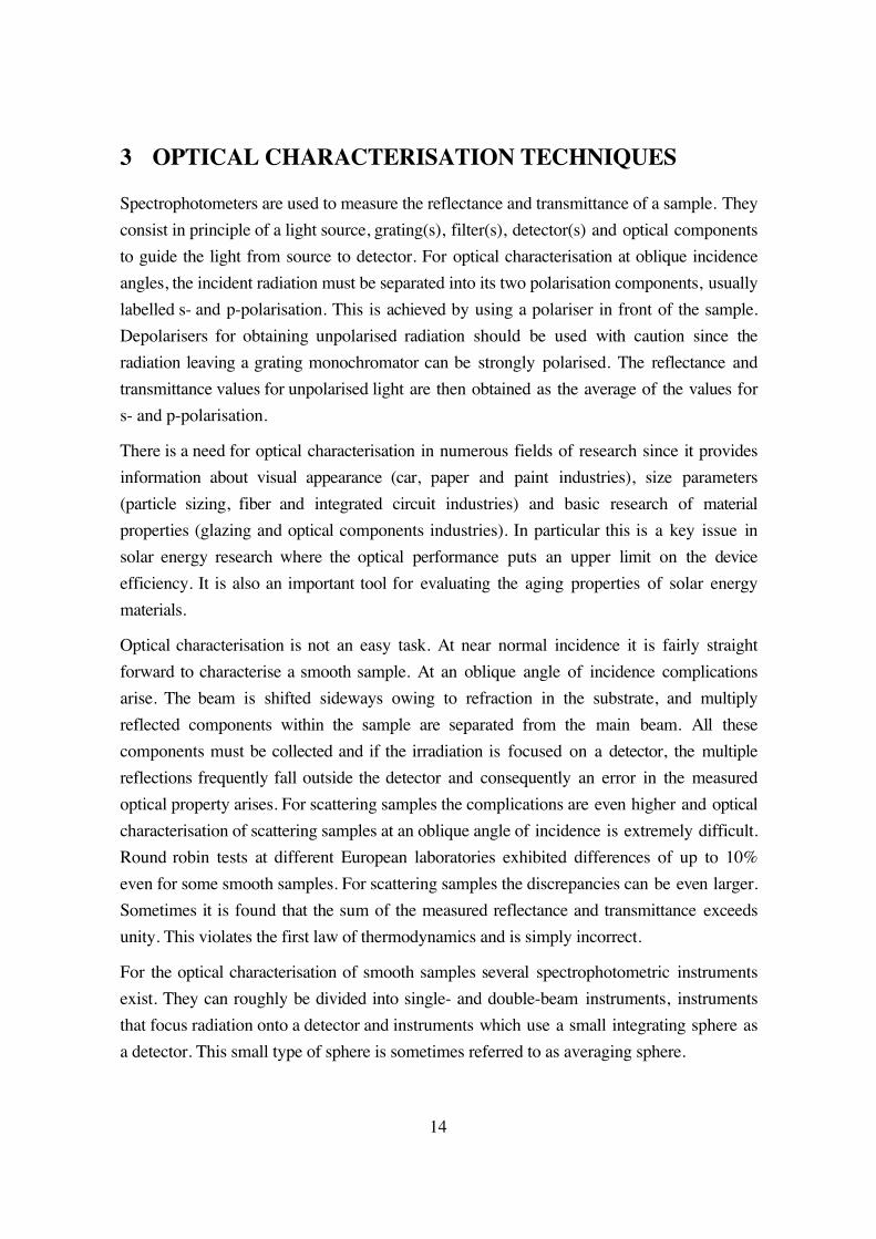
The transmittance of a glass sample having macroscopic structure as measured with a
commercial Beckman 5240 spectrophotometer and the constructed integrating transmittance
sphere spectrophotometer are illustrated in Fig. 7 in the wavelength range 0.3-2.5 µm.
20
Clearly the transmittance is higher for the T-sphere measurement due to the absence of
sphere port absorption.
0.6
0.7
0.8
0.9
1
0.4 0.6 0.8 1
T-sphT-Beck
Tra
nsm
itta
nce
Wavelength (µm)2
Fig. 7 Comparison between transmittance spectra acquired with the transmittance sphere,T-sph., and the Beckman instrument, T-Beck, for a glass with macroscopic surface texture.
3.2.2 Reflectance integrating sphere
Many components used in solar energy applications scatter radiation and clearly there is a
need to characterise them optically to compare the different components. This is possible to
do in a traditional integrating sphere, but usually only at near normal incidence. This is,
however, not sufficient, as solar irradiation is received at a surface with a range of incidence
angles since the sun moves across the sky during the day and most solar energy devices are
stationary. Therefore, it is necessary to perform optical characterisation at oblique angles of
incidence not only for transmitting solar energy components, but also for reflecting
components. An integrating sphere with a centre-mounted sample was therefore designed to
measure hemispherical reflectance versus angle of incidence[11]. Other sphere designs also
exist for angular measurements[15, 47].
In Fig. 8 the constructed reflectance sphere is depicted. The inside of the sphere is coated
with barium sulfate, which diffuses the light. The sample holder is centre-mounted and the
detector sits at the end of the sample holder. Owing to this design, the light can never reach
the detector without being diffused by the sphere wall. Another advantage with this position
is that the detector always sees the same sphere wall area, irrespective of incidence angle and
the sample is not obstructing the detector's field of view. The geometry of the sphere has a
large influence on the modelling of the sphere signal since radiation reflected within and
outside of detector's field of view must be treated separately. Absorbing elements inside the
sphere must also be taken into account for the correct modelling. This is of particular

21
importance for this sphere since the sample of the sphere is located inside it. The reference
signal is acquired with the back side of the sample holder, which is covered with barium
sulfate, facing the incident beam. It was observed that the reference signal decreased by 40%
when the reflectance of the sample mounted on the sample holder was decreased from 0.96
to 0.04. Obviously the throughput of the sphere is strongly affected by the reflectance of the
sample being measured.
I0
A1
A2 Rd
Rsp
Rw
Top view of R-sphere
Sample
Side view of R-sphere
I0A2
A1
RspRd
Rw
Detectorθ
Fig. 8 Schematic top and side views of the reflectance sphere.
By following the path from the incident beam that falls onto either the reference surface (the
backside of the sample holder) or the sample, one arrives at the following expression for the
reflectance, R
R RD R A D
D ASS
RD A
w s
r
w2 1
2 2
1
1 10+
− + −
−−
=( )
( ) cos( ) ( ) cos( )θ θ(7)
where A1 and A2 represent the fractional areas of the sphere and the sample holder,
respectively. For a more detailed discussion on the derivation of this expression see[11]. Rw
is the reflectance of the sphere wall, Ss the sample signal, Sr the reference signal, and θ the
incidence angle, cf. Fig. 8 for an illustration of the various terms. The diffusing factor, D, is
the amount of the diffusely reflected radiation that falls inside the detector's field of view in
comparison to a perfectly lambertian surface having the same reflectance. It is possible to
solve for R in Eq. (1) except for the case D=1, meaning that the reflectance of the sample is
completely diffuse. In this case we obtain
RSS
Rs
rw= (8)
It is crucial to choose the D-factor correctly. However, it is only possible to obtain exact
information about it by means of angle-resolved scatterometry, which determines the
angular distribution of the scattered radiation. This is too time consuming and generally not

22
possible. It is therefore necessary to make an estimation of this correction factor. By
experience it is possible to estimate D by a visual inspection. If the sample is perfectly
specular D=0 and for a perfectly lambertian sample D=1. In Fig. 9 a black ceramic tile
sample, provided by NBS (now known as NIST), was measured in the reflectance sphere in
the wavelength range 0.3-2.5 µm. In the figure several correction factors have been used to
calculate the reflectance spectra with Eqs. (7) and (8). The agreement between certified and
corrected spectra is best for D=0.3. This is a reasonable value of the correction factor. The
sample has a specular reflectance of approximately 0.04 and the remaining reflectance is
nearly lambertian.
0.04
0.06
0.08
0.1
0.12
0.4 0.6 0.8 1 3
D=0D=0.3D=1RatioCert.
Ref
lect
ance
Wavelength (µm)
Ratio
D=1
D=0.3
D=0
Certified
Fig. 9 Different spectra for the black reference sample for different D-values; the directsignal ratio and the certified spectrum are also included in the figure.
Another interesting phenomenon that is weakly noticeable in Fig. 9 is that the there is a
small peak just below the wavelength 2 µm both for D=0 and D=0.3. In Fig. 10 , where the
reflectance of an aluminium sample is shown, the effect is much more evident for the
sample-to-reference signal ratio spectrum. Obviously the uncorrected spectrum cannot be
correct since the reflectance is higher than unity. The peaks discernible in the uncorrected
spectrum are due to water absorption in the barium sulfate and one might think that another
sphere wall material should be used due to these annoying absorption peaks. They provide,
however, a way of checking whether proper corrections have been made. If no peaks are
present in the spectrum after correction it is likely that the reflectance has been correctly
modelled. In the short wavelength range the reflectance of the corrected spectrum is too
high. Presumably the reflectance of barium sulfate, the sphere wall material, has been
wrongly determined and this influences the correction.

23
0.8
0.9
1
1.1
0.4 0.6 0.8 1
R-abs.R-sph. (ratio)R-sph.
Ref
lect
ance
Wavelength (µm)2
Fig. 10 Near normal reflectance spectra of aluminium measured in the absolutespectrophotometer, R-abs., and the reflectance sphere. The reflectance spectra consist of acorrected spectrum, R-sph., and the direct signal ratio, R-sph. (ratio).
3.2.3 Angle-resolved scatterometer
The only instrument that measures the angular distribution of scattered light is the angle-
resolved scatterometer. The basic idea of this instrument is to illuminate a sample with
radiation and then measure the scattered radiation in all directions of the hemisphere. Since
the detector only occupies a small solid angle, the intensity of the detected signal is very
small for specular samples for measurements well off the specular direction. For the
specular direction, i.e. when the specular beam of the sample falls directly at the detector, the
signal is very high. Therefore the electronic design of the preamplification and the optical
design of the system is crucial to obtain the necessary dynamic range. The signal can easily
vary by more than ten decades when measuring smooth samples at specular and off-
specular angles. The measured quantity is the bi-directional reflectance distribution function,
BRDF[43, 48, 49], which is the scattered intensity, Ps , in a certain solid angle, Ω
BRDFP
Ps
i s
=Ω
cosθ(9)
where Pi is the intensity of the incident beam and θs the scattering angle.
In solar energy applications scatterometric measurements can be used for the evaluation of
external reflectors. Scatterometers can also be used in basic research to evaluate scattering
phenomena, for instance specular variations in the scattered intensity caused by interference
effects, which sometimes are observed in solar energy materials[50]. In Fig. 11 an outline of
such an instrument is shown. In the same figure the geometry of the instrument and the
various angles are indicated to the right. Three stepping motors are used to move the various

24
parts. Motor M1 is used to move the detector in a plane perpendicular to incidence plane.
This defines the angle φ. The second motor, M2 , moves the entire arc to the angular position
θ, which is the angle in the incidence plane. The incidence plane is the plane that is spanned
by the incident beam and surface normal of the sample. The last motor, M3 , rotates the
sample to the incidence angle θi .
He-Ne laser
Detector
Sample
M1
M2
M3 , θ i
, θ
, φ
Fig. 11 Outline of the constructed scatterometer to the left, and the geometry to the right.
From the scatterometer measurement the angle perpendicular to the incidence plane, φ, the in
plane angle, θ, and the scattered intensity are obtained. The scattering angle, θsc , is calculated
asθ θ φsc = arccos(cos( )cos( )) (10)
Reflectors having rolling grooves scatters the light in a similar fashion as a continuos
grating[51-53]. This means that reflectors should be considered to be made up of many
gratings having different periodical structures. For the evaluation of the possibility of using
external flat booster reflectors having these scattering features, it is necessary to perform
angle-resolved scatterometer measurements. By doing this, it is possible to calculate how
much of the scattered light that would fall onto a collecting device. In Fig. 12 a
scatterometric measurement of a rough cold-rolled aluminium surface at the incidence angle
60° for p-polarised light at 0.633 µm is illustrated. The orientation of the grooves are
oriented perpendicular to the incidence plane. The scattered light is bent down in a
characteristic arc.

25
Fig. 12 Scattering distribution of sheet aluminium as a function of angle in the incidenceplane, θ, and angle out of the plane, φ, for p-polarised 0.633 µm HeNe laser light at theincidence angle 60°. Note that the intensity has been normalised to the maximum intensity(i.e. the intensity in the specular direction) and that the intensity scale is logarithmic. Thespecular direction has the angles φ=θ=0. The rolling grooves are oriented perpendicular tothe incidence plane.
3.3 Double- and single-beam instruments
All three previously mentioned spectrophotomectric instruments (not including the
scatterometer) are used in the single-beam mode which has several advantages over double-
beam instruments for measurements at oblique angles of incidence. The available space in
traditional double-beam instruments is limited, which limits the sample size as well as the
size of additional accessories. For measurements at oblique angles of incidence with
double-beam integrating sphere instruments several geometry complications would arise. If
the sphere is rotated through an axis through the sample port for transmittance
measurements, the reference beam should still hit the reference plate. Two solutions of this
problem could be to have several entrance ports for the reference beam or to have an
adjustable mirror for the reference beam. The first solution has as a consequence that
absorbing elements are introduced into the sphere. From the second solution focusing

26
problems will arise since the beam is usually not well collimated. A single-beam instrument
is easier to design to avoid these problems.
The drawback for single-beam instruments, however, is the signal drift which might occur
because of a temperature drift in the room, variations of the power supply for the light
source or deposition of filament material inside the light bulb. Furthermore, if the
instrument has not been used for a long period of time water is deposited at the filters. This
water only evaporates slowly from the filters as they are being used. Consequently a drift in
the signal occurs. Therefore the filters need be warmed up for some time before the
instrument can be properly used. It is furthermore not sufficient to monitor the signal
stability at a single wavelength since the drift might vary from one part of the spectrum to
another. The temperature drift, of these three instruments, is minimised by having an
external ventilation system for the light source in combination with an air conditioning
system which keeps the laboratory space at a constant temperature slightly below the
ambient building temperature. The power supply is stabilised and no drift of the output
voltage has been detected. The maximum detected drift of the described system is of the
order of 1% per hour.
3.4 Angular optical properties of scattering solar collecting devices
The angular optical properties of scattering solar collecting devices are not well known, but
there are a few articles on this field of research[54-56]. Yet, for non-tracking devices, they
receive most of their solar irradiation at oblique angles of incidence. It is therefore important
to obtain information about the incidence angle behaviour since it determines the collection
efficiency of the device. For optimum optical angular performance the solar absorbing
surface should be as diffuse as possible. In Fig. 13 reflectance spectra of an anodised
absorber surface pigmented with nickel particles versus incidence angle in the range 5-70°
are displayed to the left and the integrated solar absorptance, calculated with Eq. (5), as a
function of angle of incidence to the right in the same figure. The spectra were acquired with
the reflectance sphere described in section 3.2.2. The solar absorptance increases for angles
up to 40°. The reason for this is that the interference maximum in the reflectance located just
below 2 µm becomes suppressed for higher incidence angles. This in combination with the
almost constant reflectance values for angles up to 40° for wavelengths shorter than
interference maximum increases the integrated solar absorptance.

27
0
0.1
0.2
0.3
0.4
0.5
0.4 0.6 0.8 1
5°20°50°70°
Ref
lect
ance
Wavelength (µm)2
Fig. 13 Reflectance spectra of a Al2O3:Ni absorber surface in the wavelength interval 0.3-2.5 µm (left graph). Solar absorptance versus incidence angle for the same sample (rightgraph). Circles correspond to experimentally obtained values.
The spectral reflectance of a pv-cell was measured as a function of angle of incidence in the
reflectance sphere, see Fig. 14 to the left. The measurement was made between the fingers
of the pv-cell. The normalised angular pv-cell efficiency, ηcell, shown to the right in Fig. 14
for the pv-cell, was calculated according to
η
λ θ λ λ
λ θ λ λcell
cell sol Si
cell sol Si
R S S d
R S S d
=
− ⋅ ⋅ ⋅
− = ⋅ ⋅ ⋅
∫
∫
( , ) ( )
( , ) ( )
.
,
.
,
1
1 0
0 3
1 1
0 3
1 1 (11)
following the nomenclature of chapter 2.
The reflectance is low in the wavelength interval where the cell is most efficient, the peak
efficiency is located at 0.66 µm. The pv-cell is completely diffuse between the fingers and
has consequently no specular component. Therefore the efficiency is very high also for high
incidence angles. At an incidence angle of 75° the drop in the efficiency is moderate and it
has only decreased by 7% in comparison to normal incidence. At wavelengths longer than
the bandgap, 1.1 µm, the reflectance is increased since the semiconductor becomes non-
absorbing and the back contact of the cell, which is made of aluminium, starts to reflect the
radiation.
90
92
94
96
98
100
0 30 60 90
Al2O
3:Ni-absorber
Sol
ar a
bsor
ptan
ce (
%)
Incidence angle ( °)

28
0
0.1
0.2
0.3
0.4
0.5
0.4 0.6 0.8 1
0°10°45°60°75°
Ref
lect
ance
Wavelength (µm)2
Fig. 14 Reflectance spectra of a monocrystalline pv-cell in the wavelength range 0-3-2.5 µm at incidence angles according to the legend, to the left. Normalised angular pv-cellefficiency for a monocrysalline silicon pv-cell, to the right. Circles correspond toexperimentally obtained values.
90
92
94
96
98
100
0 15 30 45 60 75 90
pv-eff.
Nor
mal
ised
cel
l ef
fici
ency
(%
)
Angle ( °)

29
4 OPTICAL MODELLING
The propagation of electromagnetic radiation in a medium is described by a complex
refractive index, N
N n i k= + (12)
The refraction of the radiation is described by the refractive index, n, and the damping of the
radiation by the extinction coefficient k. These so called optical constants are always
wavelength dependent.
The laws of reflection and refraction were formulated by Fresnel [57] in 1832 and are
summarised in the Fresnel equations. They relate the reflected and transmitted intensity to
the electromagnetic field at a surface in a medium. From the Fresnel equations it is possible
to derive the reflectance and transmittance from an interface with two media[58-60]. The
first medium is denoted by the subscript "1" and the second by "2". The various angular-
dependent Fresnel coefficients for the two states of polarisation, which might be parallel to
the incidence plane, p-polarised, or perpendicular, s-polarised, are given by
rN NN N
N NN N
NN N
NN N
p =−+
=−+
=+
=+
2 1 1 2
1 1 2 2
1 1 2 2
1 1 2 2
1 1
1 1 2 2
2 1
1 1 2 2
2 2
cos( ) cos( )cos( ) cos( )
cos( ) cos( )cos( ) cos( )
cos( )cos( ) cos( )
cos( )cos( ) cos( )
θ θθ θ
θ θθ θ
θθ θ
θθ θ
, r
t , t
s
p 2
(13)
where θ1 is the incident angle and θ2 the refracted angle. rs , rp , ts , and tp are the Fresnel
coefficients. t denotes transmissive and r reflective coefficients, respectively. Snell's law
relates the refractive indices of the media to the incident and refracted angles
N N1 1 2 2sin( ) sin( )θ θ= (14)
The angular dependent reflectance, Rs,p, and transmittance, Ts,p, from a single layer become,
for the respective state of polarisation
R r rNN
ts p s p s p s p, ,*
, ,
cos( )cos( )
= , T = ts,p2
1s,p
*θθ
2
1
(15)
r* meaning the complex conjugate of r and t* of t. The unpolarised reflectance and
transmittance are always given by
RR R
TT Ts p s p=
+=
+
2 2 , (16)
From these equations it is possible to derive the thin film formulae by assuming that the
electromagnetic field from the two interfaces interact with one another. For a single film one
readily obtains for the Fresnel coefficients

30
rr r e
r r e
i
i=+ ⋅
+ ⋅ ⋅
−
−1 2
2
1 221
δ
δ (17)
tt t e
r r e
i
i=⋅ ⋅
+ ⋅ ⋅
−
−1 2
1 221
δ
δ (18)
δπ
λ= −
⋅ ⋅2 2N dfilm (19)
where δ is the phaseshift and λ the vacuum wavelength. In the thin film formulae the
subscript "1" denotes the first film interface and "2" the second. The reflected intensity, R,
which henceforth is referred to as the reflectance, and the transmitted intensity, T, or
transmittance, become
R r r= ⋅ ∗ (20)
TNN
t t= ⋅ ∗2 2
1 1
cos( )cos( )
θθ
(21)
By assuming real refractive indices, i.e. non-absorbing media, it is possible to solve for zero
reflectance, provided the refractive index of the film, N2, is lower than that of the substrate,
N3. This gives
N N N2 1 3= ⋅ (22)
Thus, for zero reflectance, the refractive index of the film should be the squareroot of the
product of the substrate's and incident medium's refractive indices. This is the condition for
optimum antireflection treatment, which will be thoroughly treated in chapter 6.
At solar wavelengths the geometric dimensions of the substrate are usually much larger than
the coherence length of the probing light and the coherence is therefore lost. This means
that the resulting reflectance from the two surfaces of the substrate is obtained by
summation of the multiply reflected intensities. The reflectance is different depending on
from which side the incidence takes place if one or more of the media involved are
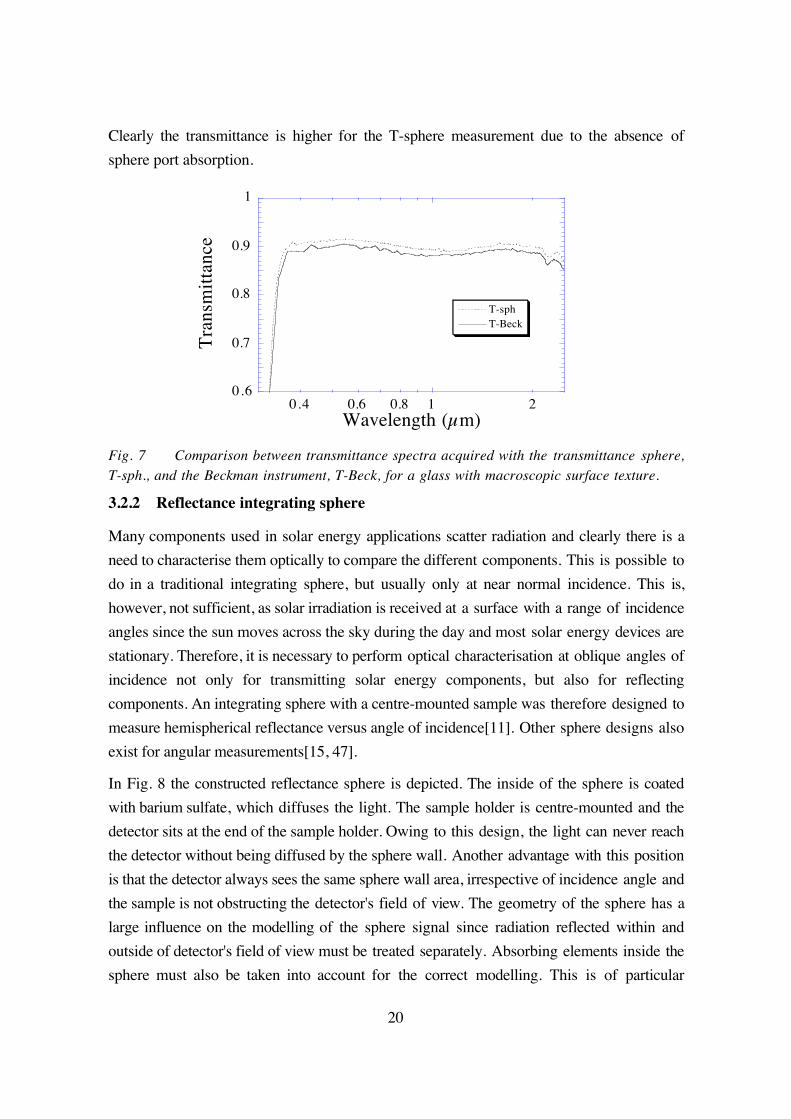
absorbing. It is therefore necessary to make a difference between which side the incidence
takes place. This is illustrated in Fig. 15 where a substrate with two identical films, one on
each side of the substrate, is depicted. The various refractive indices, the Fresnel coefficients,
and the incidence angles are also indicated. The effect of the thin film Fresnel formulae is
that they reduce the film to a single surface, which, however, has a direction dependent
reflectance. The transmittance does not have this direction dependence. For smooth surfaces
the transmittance is always identical, regardless of from which side the incidence takes
place. For the calculation of the total normal reflectance, Rtot , and transmittance, Ttot , of the
glazing with two different interfaces one arrives at
31
R RT T R e
R R etot fb
d
b bd
sub
sub= +
⋅ ⋅ ⋅− ⋅ ⋅
−
−11 2 2
2
1 221
α
α (23)
TT T eR R etot
d
b bd
sub
sub=
⋅ ⋅− ⋅ ⋅
−
−1 2
1 221
α
α (24)
where the subscript "b" means the reflectance from the inside of the sample and "f" from
the outside. The subscripts "1" in the various R and T terms in Eqs. (23) and (24) refer to
the first interface and "2" to the second. All this is illustrated in Fig. 15.The absorption
coefficient, α, is given by
απλ
=4 k
(25)
For the calculation of the total reflectance and transmittance for oblique angles of incidence,
the angular dependence of the various R and T terms in Eqs. (23) and (24) must be included
and the substrate thickness dsub→dsub/cos(θ2).
r1 , t1N1
N2
N3
N1
N4
N3
R, T
Rtot , Ttot
d1
d2
dsub
R, Tr4 , t4
r2 , t2
r3 , t3
R1f
T1
R1b
T1
θ1
θ2
Fig. 15 Thin film definition of a sandwich consisting of two films on a substrate. Thedifference in reflectance depending from which side the incidence takes place is alsoindicated to the right in the figure.

32
5 ALUMINIUM REFLECTORS
One method of increasing the output from a solar collector device is to mount a reflector in
front of the collector that reflects solar irradiation onto the absorbing unit. Since solar
reflectors are much less expensive than solar absorber devices this has a high potential of
being cost-effective and thus decreasing the cost per delivered energy unit.
The reflectors might be either flat or curved[53, 61-63]. There is a variety of different
concentrator geometries, with a concentration factor ranging from 1.5-50[4, 64]. A
particularily interesting type of concenctrator is the compound parabolic concentrator
(CPC:s) having a concentrator factor around 2-5, cf. Fig. 2 middle. For higher concentration
factors the reflectors need to be specular, while for lower concentration factors a certain
amount of diffuse reflection is acceptable. Furthermore, the reflector might be external, i.e.
directly exposed to the outdoor environment, which is always the case for planar reflectors,
or located behind a glazing[65].
A reflector should reflect as much of the useful irradiation as possible. Examples of
reflectors that reflect only a part of the solar irradiation are so-called cold mirrors[66]. They
find their use in pv-applications where it is desirable to reflect only the part of the solar
spectrum that has wavelengths shorter than the band gap of the pv-cell. Longer wavelengths
only contribute to heat generation that decreases the efficiency of the pv-cell[2, 67]. The
mirrors can, for instance, have a doped tin oxide film on top of a highly reflecting material.
For a silicon pv-cell this means that the reflected part of the intensity of the sun might be
decreased by a quarter, compared to a non-selective reflector. Still the cold mirror performs
as well as a non-selective reflector since its reflectance at useful wavelengths is as high as
the non-selective reflector. A reflector should furthermore be long-term stable at a time scale
of the life time of a solar collector, i.e. at least 20 years. Few materials will withstand this
rough requirement. The only reflector material that is inherently long term-stable is stainless
steel[68]. The solar reflectance of stainless steel is, however, too low and it is too expensive
to use in solar energy applications.
The Drude model predicts the high reflectance of metals at wavelengths longer than the
plasma wavelength. Suitable materials should therefore be sought amongst the free electron-
like materials at optical wavelengths. The problem, however, is that very few materials
exhibit free electron behaviour at solar wavelengths. Interband transitions lower the
reflectance of most metals. The only two metals exhibiting high reflectance over the entire
solar wavelength interval are aluminium and silver. Aluminium has, indeed, an interband

33
transition around 0.825 µm, but fortunately, this is quite weak. Highly specular aluminium
films made in an ultra high vacuum deposition process have a solar reflectance of 92%,
whereas silver films have 96%. In Fig. 16 the spectral reflectance, at solar wavelengths, of
stainless steel, aluminium, and silver is displayed. Aluminium's interband absorption is
clearly seen above 0.8 µm in the figure.
0
0.2
0.4
0.6
0.8
1
0.4 0.6 0.8 1
R(Ss)R(Al)R(Ag)R
efle
ctan
ce
Wavelength (µm)2
Fig. 16 Reflectance of stainless steel, aluminium, and silver at 0.3-2.5 µm.
The by far two most common reflector materials being used are silver and aluminium, which
are both highly reflective. Of these two materials aluminium is the cheaper and most
frequently used. The problem with both these materials is that their optical properties
deteriorate upon exposure to the outdoor environment at a time scale of less than one year.
They must therefore be protected by some kind of non-absorbing coating. To protect the
vulnerable aluminium surface from degradation, several techniques have been applied;
anodisation[50, 51], lacquering with PVF2 [51], laminating with PVF2 [51], PVF [51], and
PMMA[50, 69-71], vacuum deposited thin dielectric films[72], and sol-gel deposition of
thin dielectric films[73]. Another approach, for both silver and aluminium, has been to
vacuum deposit metal onto PMMA[69, 71]. Yet another method to obtain long-term stability
is second surface mirrors, where metal has been deposited onto the glass and thereafter
sealed[74, 75]. The problem with second surface mirrors is their brittleness and high
weight. Silver, as such, is never used as a substrate due to its high cost. In contrast to this, it
is possible to use sheet aluminium as substrate reflector[51, 53].
5.1 Optical properties of reflectors
In large area systems, the typical geometry for Swedish conditions for flat plate solar
collectors with external booster reflectors is depicted in Fig. 17. Since solar collectors in

34
large fields must be tilted to effectively absorb the sun’s irradiation at low solar elevation
angles they must be separated to avoid shadowing effects[51, 76]. The area between the
collector rows is thus suitable for mounting booster reflectors, which reflect the radiation
that falls between the collector rows at high solar elevation angles, so that this radiation
instead hits the absorber.
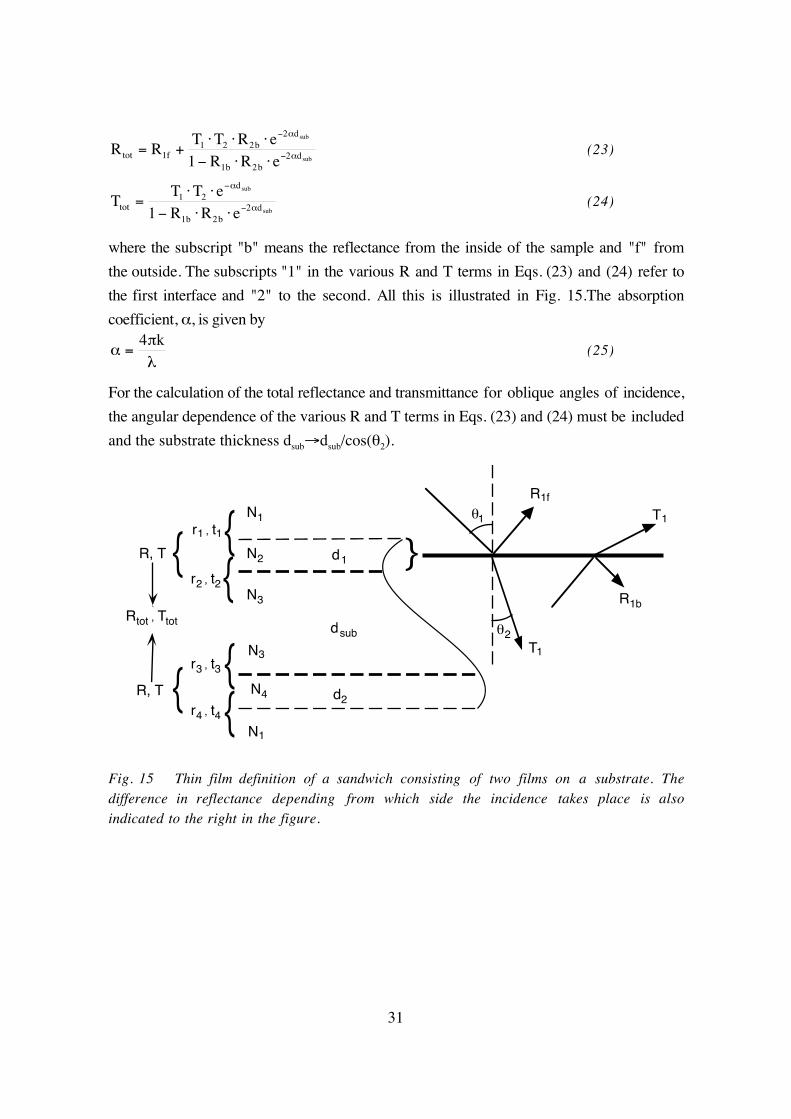
Various different reflector materials and reflector surfaces have been studied. For
applications with highly concentrating reflectors, it is necessary that the reflector is highly
specular. If not, the reflected radiation will not hit the absorbing device. For low
concentration reflector systems, it is not necessary to have a perfectly specular reflector
since the acceptance angle is much larger for low concentration than for high concentration
systems. The acceptance angle for a typical Swedish geometry is typically 20°, cf. Fig. 17.
This means that also low-angle scattering is accepted by the collector[52]. A traditional
integrating sphere with an exit port for the specular signal has an acceptance angle of about
±3.5°. This angle is not suitable to characterise reflectors having low concentrating factors.
A better acceptance angle would be ±20˚ as can be seen from Fig. 17.
40-50° 20-30°
External reflector
Standard specularrange: ±3.5°
Effective acceptancerange: ±20°
Solar collector
Fig. 17 Typical geometry of a large area solar collector system with an external boosterreflector.
5.2 Reflector materials
Different samples for long-term testing in outdoor environments have been studied for as
long as ten years at two different locations in Sweden; Älvkarleby and Studsvik. As a
construction material, rolled sheet aluminum is considered stable in normal environments.
After only eight months of outdoor exposure, however, the solar reflectance decreased by as

35
much as 10% for an unprotected aluminum sample. Not even a protective anodising layer is
sufficient to protect the surface from optical degradation over a long period of time. In Fig.
18 it is seen how the reflectance changes with aging time for an anodised sample. In the
legend in figure (a) the aging time is indicated in years. The spectra were acquired with a
Beckman 5240 spectrophotometer equipped with an integrating sphere. The spectra were
corrected with a model presented elsewhere[14].
0
0.2
0.4
0.6
0.8
1
0.4 0.6 0.8 1
Tot,0.0Spec,0.0Tot,7.14Spec,7.14
Ref
lect
ance
Wavelength (µm)2
(a) (b)
Fig. 18 Total and specular reflectance spectra for an anodised aluminium sample (a).Solar reflectance values vs. aging time in years (b).
After outdoor exposure for seven years, see Fig. 18a), the visual character of the sample is
dull. This effect is sometimes called a blooming effect and is due to formation of aluminium
hydroxides in the interface between the film and the substrate. The interference fringes in
the spectral reflectance disappear after a few years of aging since the coherence between the
two interfaces of the film decreases due to the aging. The total integrated solar reflectance
has decreased from its initial value of 87% to 76%, see Fig. 18b), and the diffuse reflectance
has increased from 7% to 40%. This is not an acceptable degradation rate since the service
time of a solar collector system including the reflector should be at least 20 years. Yet
anodised aluminium is frequently used as a reflector material, but clearly, it is not long-term
stable.
Another interesting material combination was also tested. Already anodised aluminium was
lacquered with PVF2 for one sample and laminated with PVF for two other samples.
Outdoor exposure for almost six years exhibits only a modest decrease in the total
reflectance from 83% to 79% for the PVF2 lacquered anodized aluminum sample, see Fig.
19. The diffuse part of the reflectance increased from 8% to 15%. Note that the aging time
in the legends is in years in Fig. 19a).
50
60
70
80
90
100
0 1 2 3 4 5 6 7 8
Anodised Al
Sol
ar r
efle
ctan
ce (
%)
Time (years)

36
0
0.2
0.4
0.6
0.8
1
0.4 0.6 0.8 1
Tot,0.0Spec,0.0Tot,4.03Spec,4.03
Ref
lect
ance
Wavelength (µm)2
(a) (b)
Fig. 19 Total and specular reflectance spectra for an anodised aluminum sample with aPVF2 coating (a). Solar reflectance vs. aging time in years (b).
Other studied reflector materials are
• Vacuum evaporated aluminum foil on PMMA (purchased from 3M), which is long-term
stable but expensive. Furthermore, it needs a frame since it is not self-supporting.
• Corrugated aluminum covered with PVF2 lacquer, which is resistant to outdoor
exposure. The reflectance should be slightly higher to make it competitive with other
reflector materials. The lower reflectance is, however, balanced by its low cost.
• Stainless steel, which is extremely long-term stable. No change has been noticed after
more than seven years aging, but the initial reflectance is too low, only about 66%, and it
is an expensive choice.
All studied materials are commercially available, apart from the lacquered anodised
aluminum reflector. There are, however, no reasons to assume that it is impossible to
manufacture this type of reflector on an industrial scale. The optimum choice of material
depends, of course, on the application of the external reflector. Total installation costs and
service lifetime of the reflector should be considered when choosing the reflector material.
5.2.1 Angular properties of reflector materials
Most radiation hits reflectors at high angles of incidence and consequently they should not
only be characterised at near normal incidence. A more representable angle of
characterisation for collectors used at Swedish latitudes is 60˚. Measurements were
therefore made with an angle-resolved scatterometer and with an integrating sphere
spectrophotometer, which is especially designed for angular measurements, for this
50
60
70
80
90
100
0 1 2 3 4 5
PVF2/Anodised Al
Sola
r re
flec
tanc
e (%
)
Time (year)

37
particular angle of incidence. These instruments were presented in the sections 3.2.2 and
3.2.3
5.2.2 Scattering properties of reflectors
Angle-resolved scatterometer measurements were performed to study the reflected intensity
distribution in the collector plane for vacuum-evaporated aluminium, anodised aluminium,
and cold-rolled aluminium foil samples. These three samples have drastically different
scattering properties. In Fig. 20, the scattered power for these three samples is shown versus
scattering angle. The measurements were acquired at the incidence angle 60°. The intensity
has been normalised and the intensity scale is logarithmic in the plots. In the figures θ is
measured in the incidence plane and ϕ perpendicular to the incidence plane as outlined in
Fig. 11 and explained in section 3.2.3. For all samples a characteristic arc is observed. For
the rolled aluminium foil it is particularly pronounced. The visible appearance of this sample
is dull. The two other samples also have rolling marks stemming from the rolling process
for the anodised aluminium sample and the lamination process for the vacuum-evaporated
aluminium foil. The visual appearance of the two latter samples is, however, specular.
In Fig. 21 the calculated intensity in the collector plane is shown for the three samples. Also
shown is the calculated intensity from a two-dimensional ideal lambertian sample. The
intensity of the samples has been normalised to their reflectance values at 0.633 µm. The
Anodized Al
θϕ
0
-2
-4
-6
3020
100
-10-20
-30
40
20
0
-20
log 1
0(I
nten
sity
)
θϕ
0
-2
-4
-6
3020
100
-10-20
-30
40
20
0
-20
log 1
0(In
tens
ity) Vacuum evaporated Al
Rolled Al
θϕ
0
-2
-4
-6
3020
100
-10-20
-30
40
20
0
-20
log 1
0(In
tens
ity)
Fig. 20 Angle-resolvedmeasurements of scatteredradiation for three differentreflector materials measuredat 60˚.

38
reason why the anodised aluminium sample has a lower intensity is that it has an
interference minimum at this particular wavelength. All three samples perform equally well
as reflectors whereas the lambertian sample’s intensity starts to fall immediately. Even for
the diffuse rolled aluminum foil, the intensity is almost constant in the entire collector plane.
The reason is that the rolling grooves act as a “continuous grating” and tend to bend down
the light onto the collector at oblique angles of incidence if the grooves are oriented
perpendicular to the plane spanned by the collector and reflector surface normals. This
effect is clearly seen for the rolled aluminum foil in Fig. 20. The same tendency can also be
noticed for the anodised sample. The reason for this behaviour is that the base material used
in the anodising process consists of rolled aluminium. This base material is covered with
aluminium, to smoothen out the rolling grooves. In this process the grooves are replicated,
even if to a large extent they are smoothed out. In fact, the effect of rolling grooves is also
discernible in the PMMA sample, owing to the lamination process.
0
0.2
0.4
0.6
0.8
1
0 0.5 1 1.5 2
Vac. evap. AlAnod. AlRolled AlIdeal lamb.
Inte
nsity
Height (m)
Fig. 21 Calculated intensity in the collector plane for the three samples and an ideallambertian sample.
For pv-cells connected in series, the least illuminated cell will determine the output. It is
therefore important to illuminate pv-cells evenly. A slightly diffuse reflector could be a
better choice in this application. For external reflectors in large area solar collector systems
a good choice is PVF2 coated rolled sheet aluminum or the long-term stable anodised
aluminum sample covered with PVF2.
5.2.3 Angular thin film design and properties
The reflectance at oblique incidence angles of bare aluminium and of aluminium with
optically thick, i.e. non-coherent, protective coatings is fairly constant up to high angles of
incidence. For aluminium coated with optically thin films, where interference effects are

39
important, the angular behaviour is complex, due to the interband transitions located around
0.825 µm. The transitions are manifested as a dip in the reflectance and this dip might either
be enhanced or suppressed, depending on whether an interference maximum or minimum is
obtained in the interband absorption wavelength interval. Usually reflectors are designed for
operation at near normal incidence, even though they are always operated at oblique
incidence angles[72, 73]. Aluminium coated with optically thick or semi-thick coatings such
as anodised aluminium, do not show large deviations between the near-normal and angular
optical properties. The situation is, however, different for optically thin films exhibiting one
or two interference fringes in the solar wavelength range.
The German company Alanod GmBH offers for sale aluminium reflectors which have been
sputter coated with titania and silica. The product is designed for light fittings, and
consequently it has been optimised for the visible wavelength interval. Nevertheless, it is
possible to use it for solar energy purposes. The spectral reflectance of two aluminium
reflectors with thin films, one with a protective coating of PVF2 on top of the films and
another without a protective coating, are shown in Fig. 22. The reflectance of a bare
aluminium sample is also shown. Clearly it is possible to increase the reflectance of
aluminium with thin films. The reason for having a protective coating on top of the films is
that without this coating they degrade too rapidly in an outdoor exposure situation.
0.5
0.6
0.7
0.8
0.9
1
0.4 0.6 0.8 1
CoatedUncoatedAl
Ref
lect
ance
Wavelength (µm)2
Fig. 22 Spectral reflectance at solar wavelengths of aluminium and of aluminium havingthin titania and silica films without (uncoated) and with (coated) a PVF2 protective layer.
From the reflectance spectra and ellipsometric measurements, optical constants of the films
were retrieved. The optical constants of aluminium were calculated from angular reflectance

40
measurements for an anodised aluminium sample for which the alumina film was gently
etched off with chromic acid. Using the Fresnel formalism, see chapter 4, these optical
constants were used to calculate the angular-dependent total integrated solar reflectance for
different titania and silica film thickness. Since the internal quantum efficiency of a pv-cell,
Scell , varies strongly with the wavelength where the solar irradiance spectrum, Ssol, is
considerable, it is necessary to take the internal quantum efficiency into account in the
calculations of the quality number as described in chapter 2. In Fig. 23 the internal quantum
efficiency together with a solar spectrum are illustrated.
0
200
400
600
800
1000
1200
0
10
20
30
40
50
60
70
80
0.4 0.6 0.8 1
AM 1.5 IQE (%)
Irra
dian
ce (
Wm
-2µ
m-1
)IQ
E (%
)
Wavelength (µm)2
Fig. 23 Wavelength internal quantum efficiency, IQE, of a pv-cell and an ISO AM 1.5solar spectrum.
In principle one should also include the wavelength dependent absorption of solar absorber
surfaces for the calculation of the integrated solar reflectance. Since today’s absorber
surfaces are highly selective, having integrated solar absorptance values in excess of 0.95,
and the variation in the absorption at wavelengths where the sun’s irradiance is high, the
influence of not taking into account the wavelength dependent absorption will not lead to
large errors.
To obtain a single quality number of a reflector, which has varying incidence angle-
dependent optical properties, it is necessary to assign each incidence angle a statistical
weight. For tracking solar devices this is, however, not necessary. These weights are, of
course, system-dependent since different reflector geometries reflect radiation differently.
Consequently care must be taken when using them. In Fig. 24 a) and b) the calculated
integrated solar and pv-cell reflectance are shown versus silica and titania film thickness for
the uncoated sample for film thickness in the range 0-350 nm. In Fig. 25a) and b) the same

41
quantities are plotted for the PVF2-coated sample. The calculations were performed
assuming the following expression.
Rs cR R R R R R
,( ) . ( ) . ( ) . ( ) ( ) . ( ) .
. . . . .=
° ⋅ + ° ⋅ + ° ⋅ + ° ⋅ + ° ⋅ + ° ⋅
+ + + + +
30 0 3 40 0 5 50 0 7 60 1 70 0 7 80 0 5
0 3 0 5 0 7 1 0 7 0 5(26)
where Rs,c denotes either the integrated solar or pv-cell reflectance. These statistical weights
are characteristic for a flat booster reflector. A more careful analysis would require ray
tracing, where the particular geometry and shadowing effects are taken into account. This
was, however, not performed.
a) b)
Fig. 24 Angular averaged integrated solar, a), and pv-cell reflectance, b), versus titaniaand silica film thickness for a reflector having thin titania and silica films.
a) b)
Fig. 25 Angular averaged integrated solar, a), and pv-cell reflectance, b), versus titaniaand silica film thickness for a reflector having thin silica and titania films and a protectivePVF2 coating.
Clearly the titania film should have an approximate thickness of 100 nm for all applications,
whereas the silica thickness should be different depending on the application. Without a
0 50 100 150 200 250 300 3500
50
100
150
200
250
300
350
Silica thickness
0.78
0.8
0.82
0.84
0.86
0.88
0 50 100 150 200 250 300 3500
50
100
150
200
250
300
350
Silica thickness
0.83
0.84
0.85
0.86
0.87
0.88
0.89
0.9
0 50 100 150 200 250 300 3500
50
100
150
200
250
300
350
Silica thickness
0.81
0.82
0.83
0.84
0.85
0.86
0.87
0.88
0.89
0 50 100 150 200 250 300 3500
50
100
150
200
250
300
350
Silica thickness
0.76
0.78
0.8
0.82
0.84
0.86
0.88

42
PVF2 coating the silica film thickness should be approximately 150 nm for both pv-cell and
solar collector applications. With an additional PVF2 coating the optimum silica film
thickness should be 125 nm for a solar collector application, whereas it should be 95 nm for
a pv-cell application. The optimum film thickness is more sensitive to the titania thickness
than to the silica thickness due to the higher refractive index of titania. In Fig. 26 the angle
dependent integrated total solar and pv-cell reflectance versus incidence angle are shown. At
higher incidence angles the reflectance values increase. The reason for this is that the
0.825 µm dip in the reflectance of aluminium becomes suppressed due to interference
effects. At high incidence angles the integrated reflectance values are higher for the sample
with thin films than for aluminium.
86
88
90
92
94
96
98
100
0 15 30 45 60 75 90
Rsol
TiO2/SiO
2/Al
Rsol
Al
Sol
ar r
efle
ctan
ce (
%)
Angle ( °)
AlSiO
2 160 nm
TiO2 100 nm
a) b)
Fig. 26 Angular dependent solar, a), and pv-cell reflectance, b), for an aluminiumreflector having thin silica and titania films. The film thicknesses are indicated in the insets inthe figures.
For the optimum film thicknesses, mentioned above, the angle-dependent solar and pv-cell
reflectance of the PVF2 coated sample are shown in Fig. 27a) and b) together with
aluminium’s reflectance. The integrated solar and pv-cell reflectance amount to 91% at the
interesting angles, which is a very high value. For anodised aluminium they amount to 84%
and 80%, respectively.
84
86
88
90
92
94
96
98
100
0 15 30 45 60 75 90
Rcell
TiO2/SiO
2/Al
R cell
Alpv
-cel
l ref
lect
ance
(%
)
Angle ( °)
AlSiO
2 140 nm
TiO2 100 nm

43
86
88
90
92
94
96
98
100
0 15 30 45 60 75 90
Rsol
Lacq./TiO2/SiO
2/Al
Rsol
Lacq./Al
Sola
r re
flec
tanc
e (%
)
Angle ( °)
AlSiO
2 125 nm
TiO2 95 nm
Lacquer
a) b)
Fig. 27 Angular dependent solar, a), and pv-cell reflectance, b), for an aluminium samplewith silica and titania films with a protective PVF2 coating. The film thicknesses are indicatedin the insets in the figures.
The anomalous behaviour of the incidence angle properties, which is most noticeable for the
PVF2 uncoated aluminium sample, disappears for the PVF2-coated sample. The reason for
this is that the critical angle of PVF2 is 45°. Thus the highest incidence angle at the
underlying thin films is restricted to angles lower than this critical angle.
The reason for the larger improvements for pv-cell than for solar collectors applications is
that a pv-cell operates in a narrower wavelength range. The enhancement in the integrated
reflectance thus becomes larger since tailoring of the optical properties is more efficient in a
limited wavelength interval.
As regards the long-term stability of these two different reflectors the unprotected sample
can never be used in an outdoor climate since it degrades at a time scale of a few years.
After only two years of outdoor aging a blooming effect was clearly manifested as large
whitish spots. For some applications the reflector is placed under a glazing and it is possible
that this reflector is long-term stable in this kind of environment.
80
85
90
95
100
0 15 30 45 60 75 90
Rcell
Lacq./TiO2/SiO
2/Al
Rcell
Lacq./Al
pv-c
ell r
efle
ctan
ce (
%)
Angle ( °)
AlSiO
2 95 nm
TiO2 95 nm
Lacquer

44
6 SINGLE FILM ANTIREFLECTIVE COATINGS
Almost all solar collectors have a glazing made of glass in front of the absorber surface to
protect them from the degrading environment and to decrease heat losses. The reason for
choosing glass as glazing material is manifold. Firstly, and most importantly, it is highly
transparent at solar wavelengths. Uncoated low-iron glass has a solar transmittance of
approximately 90%. The region of high transparency is confined to the wavelength range
0.38-4 µm and the solar spectrum is essentially also confined to this region. Secondly, glass
is long-term stable well beyond the expected life time of a solar collector. Thirdly, its
mechanical strength and scratching resistance are very high, especially since cover glazings
for solar collectors almost always are tempered to avoid thermal breakage due to the strong
temperature variations they might be subject to. A fourth reason is that glass manufacturing
techniques are extremely well developed and widely used. Furthermore, the most abundant
elements in the Earth's crust are silicon and oxygen, which are the main constituents in
glass. A typical glass composition is: 73% SiO2 , 14% Na2O , 9% CaO , and 4% by volume
of MgO. The abundance of silica, together with the float glass technique has resulted in very
low production costs for glass. Low-iron glass, however, is considerably more expensive
than ordinary float glass due to its low useage and higher production costs. Polymers are an
alternative material category but they are more expensive and the scratching resistance is
poor.
Ordinary float glass contain iron oxide which decreases the transmittance. The presence of
iron oxide in glass is manifested as a broad dip around 1.1 µm and the transmittance in the
UV also decreases with an increased iron oxide concentration. The integrated solar near-
normal transmittance for float glass containing 0.01-0.1% iron oxide is 80-85%. For low-
iron glass the near-normal integrated solar transmittance is 90%. This is the upper limit for
the transmittance of glass. It is, however, possible to further increase the transmittance by
applying an optically thin film. This process is called antireflection treatment and the
theoretical background of it was outlined in chapter 4.
For a single antireflective film the transmittance is always higher than that of the substrate.
Glass might also be covered with multilayer films that have higher transmittance in a narrow
wavelength interval. Nevertheless, for wavelengths outside this design interval the
transmittance is lower than that of the bare substrate. A solar collector operates in a very
broad wavelength interval and it is not possible to obtain high transmittance throughout this
entire wavelength interval with a multilayer stack consisting of high and low-index films. In
Fig. 28 the measured near-normal spectral transmittance for a low-iron glazing is displayed

45
before and after single film antireflection treatment[77]. The maximum transmittance
amounts to 99.5% which is very close to the theoretical upper limit. A solar spectrum
(AM 1.5) is also shown in the same figure.
0.5
0.6
0.7
0.8
0.9
1
0
200
400
600
800
1000
1200
0.4 0.6 0.8 1
AfterBefore
AM 1.5
Tra
nsm
itta
nce
Solar irradiance (W
m-2µ
m-1)
Wavelength (µm)2
Fig. 28 Measured spectral transmittance, 0.3-2.5 µm, before and after antireflectiontreatment. A solar spectrum, AM 1.5, is also illustrated.
Several solar selective devices carry antireflective coatings. Selective solar absorbers are
frequently made using thin film deposition techniques. Since the absorber surface has a
thickness of approximately 0.3 µm, thin film effects might be manifested as a local
maximum in the reflectance. Sometimes an antireflective coating is used to suppress this
maximum[78]. All pv-cells have one or more antireflective coatings to reduce the reflective
losses, which are high due to the high refractive index of the used materials. All glazings for
solar collectors will probably have an antireflective coating in the future as low cost
antireflection treated glazings are now appearing on the market. The integrated solar
transmittance of the glazing in Fig. 28 before antireflection treatment is 90% and 95% after
treatment. For a solar collector this increment in the solar transmittance would lead to an
increment of 10% in the annually collected energy. Thus it is cost-effective to install an
antireflection treated cover glazing, provided the added cost of the antireflection treatment
does not exceed 10% of the system's total cost. Furthermore, since antireflection treatment
increases the collected energy per area unit, it is possible to decrease the solar collector area,
which further reduces the costs.

46
6.1 Historical notes and background
Historically, thin film optics, of which antireflection coatings are a very important subgroup,
was firstly studied in soap bubbles and fatty patches by natural philosophers such as R.
Hook and R. Boyle in the 17th century. The explanation for these thin-film phenomena was
not explained in a satisfactory way until 1833 by G.B. Airy. In 1873 all theoretical aspects
were founded on J. C. Maxwell's famous "A treatise on electricity and magnetism". The
first antireflection coating ever made was presumably by J. Fraunhofer in 1817. He etched
glass which had been exposed to the atmosphere for a long period of time with concentrated
sulphuric and nitric acid. As a result of the etching process he noted that the reflectance was
strongly reduced[79]. In an article [80] the optics manufacturer D. Taylor happily stated
about telescope lenses "...we are very glad to be able to reassure the owner of such a flint
[glass] that this film of tarnish generally looked upon with suspicion, is really a very good
friend to the [telescope] observer, inasmuch as it increases the transparency of his
objective". Taylor went on to develop a chemical etching process to artificially form
tarnished films, which today we call antireflective coatings. A modern telescope would
simply not work without antireflective coatings since the image would become blurred due
to all the reflections in the various lenses, and the transmittance of the lens system would be
too low.
For an optimum single-layer antireflective film it is necessary that the index of refraction of
the film should be less than 1.3, provided the substrate is made of glass, which is the most
common glazing material used in solar energy applications. The problem is that no solid
material having such a low refractive index is found in nature. The material having the
lowest known refractive index of which it is possible to make a thin film is magnesium
fluoride, MgF2, which has a refractive index of 1.38 in the visible wavelength range. Yet
lenses for spectacles are antireflection coated with this material. The polymer material
Teflon has a refractive index of 1.31 at visible wavelengths, but it is very difficult to make a
thin non-absorbing film of it. At best it is possible to make a thick film, which reduces the
reflectance by the refractive index matching between the glass and the air[81]. The only
known technique for achieving refractive index values as low as 1.3 or lower is to obtain a
porous structure that has an intermediate refractive index of the host material and the
surrounding medium, which is usually air. Such a porous structure might be obtained by a
whole set of deposition techniques.
The first techniques, studied by Fraunhofer and Taylor, were based on etching of the glass
in hydrofluoric, nitric, and/or sulphuric acid. These early etching techniques were far from
being optimum and required long treatment times, up to more than one day. Shorter etching

47
times were obtained with an improved technique[82-85], where the glass was etched at an
elevated temperature in fluosilicic acid. It is possible to obtain antireflective coatings with
excellent optical and mechanical properties by means of this method. A company in
Denmark, Sunarc, manufactures antireflective coated glass on a commercial basis using this
technique. A disadvantage with this method is that glass containing boron is not etchable,
and glazings for high temperature applications usually contain boron. Furthermore, the
process must be tuned in each time glass from a different batch is etched, since the
technique is very sensitive to the chemical composition of the glass. An alternative etching
technique is the phase separation/etching process[86]. In this process the glass is heated up
to roughly 600 °C for a long period of time. How long depends on the temperature; the
higher the temperature the shorter the treatment time. This induces a phase separation in the
glass. Prior to the etching process a pre-etching process in aqueous ammonium bifluoride
solution is done. The surface layer is then etched in a mixture of fluosilicic acid and
ammonium bifluoride vapor acid. In this process a graded index film is formed and the
optical properties of samples obtained by this technique are unsurpassed. The reflectance is
below 1% in the entire wavelength range of solar irradiation. The disadvantage with this
technique is the long treatment time and the aggressive chemicals used.
One usually differs between two different techniques used to obtain antireflective films;
additive and subtractive. In the latter case material is removed from the substrate and in the
former material is added. The etching processes are subtractive. The additive ones normally
consist of deposition of small silica particles[77, 87-96], but attempts have also been made
with high rate sputtering of aluminium oxyfluoride[97]. The optical properties of the latter
coatings are inferior to the previously mentioned ones. It is also possible to attain the
necessary low refractive index for antireflection treatment with a subwavelength surface
relief grating[98, 99]. The theory is extensively treated elsewhere[100].
Glass has typically a refractive index of 1.52 at visible wavelengths. This results in a
reflectance of about 4.3% from one side. Taking multiple reflections into account,
calculating with Eq. (23), it is found that the reflectance from two sides is 7.9%. With a
single layer film it is possible to achieve zero reflectance, but only for a certain wavelength.
This wavelength is usually referred to as the design wavelength. The optical thickness of the
film, which is the product of the refractive index and the physical film thickness, determines
the design wavelength, and the refractive index determines how close to zero the reflectance
becomes.
At Swedish latitudes a typical incidence angle is 30-40° for a solar collector. The solar
transmittance was therefore calculated at the incidence angles 0, 30, and 45° with the Fresnel

48
formulae, cf. Fig. 29, assuming constant refractive indices. The optimum film thickness is
slightly different for different incidence angles, the maxima in the figure are, however, fairly
flat. The minimum in the reflectance should be located at about 0.65 µm for optimum
antireflection function.
90
92
94
96
98
100
0 50 100 150 200 250 300 350
Tsol
(0°)T
sol (30°)
Tsol
(45°)
Sol
ar t
rans
mit
tanc
e (%
)
Film thickness (nm)
Fig. 29 Integrated solar transmittance versus film thickness at 0, 30, and 45° angle ofincidence.
6.2 Film preparation and optical properties of antireflective coatings
Antireflective films were made with the dip-coating method and in Fig. 30 an experimental
set up using this method is depicted.
Electric motor
Silica sol
Substrate
v
Fig. 30 Dip coating set up.
There are, however, several other deposition methods for the deposition of antireflective
coatings; spin coating, bar coating, roll coating, spraying, meniscus coating[101]. The

49
deposition method used within this work was the dip coating method, where the substrate is
immersed in a sol and withdrawn at a controlled speed. There are several advantages of
using dip coating. It is easy to build an experimental set up. Furthermore, both sides are
coated at the same time, and there are no particular substrate size limitations.
The optical characterisation of the antireflective films was carried out using two instruments;
the absolute spectrophotometer, cf. chapter 3.1, which was used for reflectance and
transmittance measurements, and a total integrated scatterometer [102] to analyse the
scattering properties of the antireflective films. In Fig. 31 the diffuse transmittance of a
sample before and after antireflection treatment is shown. In the visible wavelength range,
0.4-0.7 µm, the diffuse scattering is below 0.1 %, which is a very low value. This is an
indication of very low surface roughness. The low scattering level means that the surface is
of high optical quality and can therefore also be of interest for window applications. A
problem, however, is the hygroscopic properties of this kind of film. The films tend to
absorb humidity[103], which is evaporated at temperatures beyond normal room
temperature. In a solar collecting application this is not a limiting factor since the sun heats
up the glazing to temperatures well beyond the onset temperature of evaporation. For a
window which is not exposed to direct solar irradiation this is a serious drawback. The
absorbed water increases the refractive index and the antireflective properties are lost to a
large extent. The reflectance and transmittance measurements obtained with the absolute
spectrophotometer are presented in the subsequent sections of this chapter in association
with the various aspects of antireflection treatment.
0
0.02
0.04
0.06
0.08
0.1
0.4 0.5 0.6 0.7 0.8 0.9 1
Tdiff(Sub)Tdiff(AR)
Dif
fuse
tra
nsm
ittan
ce (
%)
Wavelength (µm)
Fig. 31 Diffuse transmittance for a sample before and after antireflection treatment in thewavelength interval 0.4-1.0 µm.

50
The physical shape of the silica particles determines how low the reflectance becomes. For
spherical particles the size distribution should be as narrow as possible, i.e. monodisperse,
since equally sized particles potentially give higher porosities. In Fig. 32 a transmission
electron micrograph of mondisperse silica particles is depicted. The thickness of a deposited
film is mainly determined by the physical properties of the used solution. The viscosity,
surface tension, and silica particle concentration will have a strong influence on the resulting
film thickness. Both the viscosity and the surface tension are affected by the temperature.
The surface tension can be altered by adding a surfactant.
50 nm
Fig. 32 Transmission electron micrograph of monodisperse silica particles. The size isapproximately 40 nm.
Several silica sols from the Swedish company Eka Chemicals AB were studied. It was
found that a monodisperse sol containing particles in the size range 40-60 nm was
optimum. For smaller silica particles the sol was prone to coagulation when mixed with
ethanol. By decreasing the pH-value of the solution it is possible to avoid this problem. At
lower temperatures it was difficult to obtain a continuous film since discrete droplets were
formed at the substrate, with non-uniform film formation as a consequence. The best films
were formed in the temperature range 25-30°C. For a complete treatment of the chemistry of
silica sols, see [104].
The sol was prepared by mixing water, ethanol, and silica particles. A typical recipe was
88% by volume ethanol and 12% by volume silica sol. The used silica sol contained 174 g/l
silica or 16% by weight. The ethanol may be substituted by water. By doing this the

51
viscosity and the surface tension are increased, which affects the film quality adversely. The
film becomes inhomogeneous. The cure is to add a small amount of surfactant. This will,
however, decrease the adhesion. If this process is to be commercialised the ethanol content
should be kept low since the sol must be flame proof. This means that the ethanol
concentration should be kept below 50% by volume. The ethanol/water to silica sol ratio can
be varied within a wide range, still resulting in a thin, smooth film.
Prior to the coating process the substrates were thoroughly cleaned. First the substrates
were mechanically cleaned with a dishbrush using detergent. Afterwards they were rinsed in
hot tap water and deionesed water. The second step consisted of an ultrasonic bath cleaning
process at 50°C in deionised water. The samples were stored in deionised water until they
were to be dipped to prevent contamination. The water was removed with compressed air. It
is fairly easy to determine how clean the glass substrate is. If a continuous water film is
formed on the substrate a continuous sol film will also be formed.
The withdrawal rate has a strong influence on the thickness of the liquid film that is formed
in the dip coating process, the higher the withdrawal rate the thicker the film. A suitable
withdrawal rate, which is easily controlled and does not produce any waves in the liquid, is
in the range 3-10 mm/s.
Antireflective films were prepared with the dip coating process at withdrawal rates in the
range 3-8 mm/s. Thin micro slides with low iron content were used as substrates. The
samples were characterised with the absolute spectrophotometer in the wavelength range
0.3-2.5 µm at the incidence angle 30°, see section 3.1. The reason for choosing this
particular incidence angle is that most solar energy is received at this angle. In Fig. 33 the
results of the optical measurements are displayed. Clearly the wavelength of maximum
transmittance is displaced towards longer wavelengths for higher withdrawal rates, which
implies that a thicker film was obtained. There is a tendency that the maximum transmittance
decreases for longer wavelengths. This effect is due to dispersion in the optical constants of
the substrate and the film.

52
0.9
0.92
0.94
0.96
0.98
1
0.4 0.6 0.8 1
345678Sub.
Tra
nsm
itta
nce
Wavelength (µm)
Withdrawalrate (mm/s)
Tsol
(%)
96.296.496.196.396.195.991.2
2
Fig. 33 Transmittance spectra acquired at an incidence angle of 30° for a substrate andfor films made at different withdrawal rates. The legend indicates the withdrawal rate and thetotal integrated solar transmittance.
6.3 Mechanical properties of antireflective films
The disadvantage of using the sol process, in comparison to the etching process, is that the
particles are weakly bonded to the underlying substrate. The scratch resistance is therefore
very poor. If this kind of coating is to be used in solar collectors the mechanical properties
must be improved since the glazing is subject to mechanical wear. For instance, all handling
of the glazing after the deposition will be extremely difficult, since the film easily peels off.
Furthermore, precipitation will abrade the film surface that faces the sun. Snow loads sliding
off the glazing are another source of abrading.
Baking the film at an elevated temperature is one way of improving the mechanical
properties. Films were baked at different temperatures in the range 500-575 °C for different
periods of time. The adherence improved but was still not satisfactory since the film was too
easily removed in a scratching test.
Cover glazings for solar collectors should be tempered so as to avoid thermal breakage due
to the elevated temperatures they are subject to. A large antireflection treated sample was
prepared and tempered at 700 ˚C in a commercial tempering furnace. After the tempering
process the adherence of the film was strongly improved. In Fig. 34 the spectral reflectance
of bare float glass and of antireflection treated float glass after tempering are displayed.
Clearly the antireflective properties are preserved after the tempering process. The

53
wavelength position of the reflectance minium is not optimum, however. The minimum
should be located at 0.65 µm for optimum optical function as a cover glazing for a solar
collector. At this optimum wavelength the dip in the reflectance would have been lower since
the refractive index matching between the film and the substrate would have been closer to
its optimum value. The tempering process is necessary for antireflective films since it
radically improves its mechanical properties. This is no drawback to this process since cover
glazings must be tempered anyway to avoid thermal breakage. The improved mechanical
properties are an added bonus.
0
0.02
0.04
0.06
0.08
0.1
0.4 0.6 0.8 1
SubstrateTempered
Ref
lect
ance
Wavelength (µm)2
Fig. 34 Reflectance spectra of a float glass sample and of an antireflection coated floatglass sample after tempering.
It is believed that above the softening temperature of glass, 600 ˚C, physical bonds are
formed between the particles in the film and the substrate. This is presumably the reason for
the improved adhesion. Interestingly, the optical changes were very small. Generally it is
believed that baking makes the film thinner and that it also increases the film density, which
should result in a higher refractive index. Only a small decrease in the transmittance was
noticed, cf. Fig. 35 where the transmittance before and after baking is illustrated. The
wavelength of maximum transmittance decreased from 0.63 to 0.60 µm after baking and the
maximum transmittance decreased from 99.1 to 99.0%. A possible explanation for the small
changes [89] could be that hydroxyl groups are released and as a result the porosity is
increased. The chemical change from hydroxide to oxide results in a film with a higher
refractive index. For the optical thickness these two effects cancel each other.

54
0.95
0.96
0.97
0.98
0.99
1
0.4 0.5 0.6 0.7 0.8
Before bakingAfter baking
Tra
nsm
itta
nce
Wavelength (µm)
Fig. 35 Transmittance spectra at visible wavelengths before and after baking.
It has been shown that antireflective films made with the etching process are long-term
stable in outdoor conditions for at least seven years[81]. No such long-term tests have been
made with films made from silica sols. Cathro et al. [87] performed one-year-long outdoor
testing and no noticeable differences in the antireflective properties were noticed. Samples
made at Uppsala University and Fraunhofer Institut für Solare Energisysteme in Freiburg,
Germany, were aged in various outdoor climates for up to one year. It was found that the
transmittance decreased for some of the samples made with the silica sol dip coating
method[105]. These samples were not, however, tempered. The results are in contradiction
to the study of Cathro [87] and further investigations need be carried out. The study of
tempered samples would be of particular interest. It is believed that the mechanical wear of
the film is likely to be smaller owing to the high mechanical strength of the film. As yet no
aging mechanisms of films made with the dip-coating method have been identified and it is
therefore uncertain to predict long-term stability even for antireflective films which have
been tempered.

55
7 OPTICAL PROPERTIES AND SYSTEM PERFORMANCE
By means of spectrophotometric measurements it is possible to determine the optical
properties of the different components of a solar collecting system. The measurements can
be used to classify the components, but these measurements have an even higher value in
that they provide simulation programs with accurate input data. A few examples of this are
presented in the following sections. These examples illustrate the importance of accurate
optical characterisation of the components in a solar energy system.
7.1 Glazings and reflectors for solar collectors
Due to aesthetic reasons and to reduce glare, glazings having macroscopic structures on one
side are used as cover glazings for solar collectors. It is demonstrated [106] that these
structures should be oriented outwards. If not, the transmittance decreases due to increased
internal reflections in the surface irregularities. In particular, this effect is noticeable at
higher incidence angles, where even total internal reflection may occur. The steeper the
macroscopic textures, the larger the difference between the two texture orientations
becomes. A glazing with the texture facing outwards exhibits similar angular optical
properties as a flat glazing. In Fig. 36 the transmittance versus angle of incidence at
0.55 µm is shown for glass having macroscopic texture. The glass was measured with the
transmittance sphere outlined in section 3.2.1 and with the structure facing either out from
the sphere or in, cf. the inset in the figure for an explanation of "In".
0.75
0.8
0.85
0.9
0.95
0 10 20 30 40 50 60 70
InOut
Rel
ativ
e tr
ansm
itta
nce
Angle ( °)
R
T
"In"
Fig. 36 Relative transmittance versus incidence angle of a glass sample with macroscopictexture as measured. The texture was either facing "In" (see inset) or "Out". Markerscorrespond to measured values.
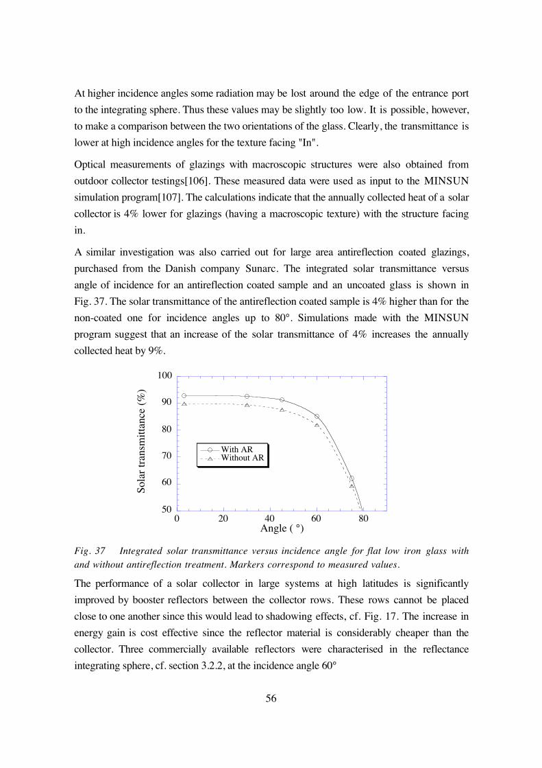
56
At higher incidence angles some radiation may be lost around the edge of the entrance port
to the integrating sphere. Thus these values may be slightly too low. It is possible, however,
to make a comparison between the two orientations of the glass. Clearly, the transmittance is
lower at high incidence angles for the texture facing "In".
Optical measurements of glazings with macroscopic structures were also obtained from
outdoor collector testings[106]. These measured data were used as input to the MINSUN
simulation program[107]. The calculations indicate that the annually collected heat of a solar
collector is 4% lower for glazings (having a macroscopic texture) with the structure facing
in.
A similar investigation was also carried out for large area antireflection coated glazings,
purchased from the Danish company Sunarc. The integrated solar transmittance versus
angle of incidence for an antireflection coated sample and an uncoated glass is shown in
Fig. 37. The solar transmittance of the antireflection coated sample is 4% higher than for the
non-coated one for incidence angles up to 80°. Simulations made with the MINSUN
program suggest that an increase of the solar transmittance of 4% increases the annually
collected heat by 9%.
50
60
70
80
90
100
0 20 40 60 80
With ARWithout AR
Sola
r tr
ansm
itta
nce
(%)
Angle ( °)
Fig. 37 Integrated solar transmittance versus incidence angle for flat low iron glass withand without antireflection treatment. Markers correspond to measured values.
The performance of a solar collector in large systems at high latitudes is significantly
improved by booster reflectors between the collector rows. These rows cannot be placed
close to one another since this would lead to shadowing effects, cf. Fig. 17. The increase in
energy gain is cost effective since the reflector material is considerably cheaper than the
collector. Three commercially available reflectors were characterised in the reflectance
integrating sphere, cf. section 3.2.2, at the incidence angle 60°

57
1. PVF2 coated aluminium from Gasell AB in Sweden. Total reflectance, Rt=0.635,
specular reflectance, Rs=0.572
2. Bright anodised aluminium from Alanod GmbH in Germany (product number: 402
G/S). Rt=0.845, Rs=0.803
3. Second surface silver mirror from Electroverre in Switzerland, Rt=Rs=0.953
The results of the optical characterisation, at the incidence angle 60°, of these reflectors are
presented in Fig. 38.
0.2
0.3
0.4
0.5
0.6
0.7
0.8
0.9
1
0.4 0.6 0.8 1
Glass/AgAl2O3/AlPVF2/Al
Ref
lect
ance
Wavelength (µm)2
Rsol=84.5%R
sol=95.3%
Rsol
=63.5%
Fig. 38 Spectral reflectance at the incidence angle 60° of three commercially availablereflectors. The corresponding total solar reflectance values are displayed in the inset.
From simulations it was found that by changing the reflector from PVF2 coated aluminium
to anodised aluminium, the collected annual energy output increases by 8%. A second
surface silver mirror would yield an increase of 20%.
A MaReCo (Maximum Reflector Collector) is a heavily truncated asymmectric CPC
collector especially designed for high latitudes[65]. The influence on the collected annual
heat by changing the reflector from anodised aluminium to a second surface silver mirror
was analysed by means of simulations with the MINSUN program. It was found that the
collected annual energy output increased by 19% for the operation temperature 50°C.

58
7.2 Reflectors and glazings for pv/t-hybrids
The optical efficiency of a photovoltaic-thermal hybrid system with concentrating
aluminium compound parabolic concentrators (pv-t CPC) was analysed[56]. The theoreti-
cally expected efficiency, ηopt, th , for electricity production of this system is calculated as
ηopt th
cell cell reflector cellbeam
sol
apperture
T A A RSS
A,
( )=
+ ⋅(27)
where Ax denotes the respective areas, cf. Fig. 39. Rcell is the integrated pv-cell reflectance,
calculated from Eq. (3), Tcell is the integrated pv-cell transmittance of the glazing, which is
calculated from Eq. (3) by substituting the spectral reflectance with the spectral
transmittance. Sbeam and Ssol are the direct and total solar irradiance, respectively. During a
clear day the ratio between the direct and the total solar irradiance is approximately 0.9.
The integrated pv-cell reflectance, cf. Eq. (3), was calculated from optical constants as a
function of angle of incidence. The optical constants were retrieved from reflectance
measurements at different angles of incidence and from ellipsometric measurements. The
pv-cell transmittance values were one percentage point higher than those in Fig. 37. The
used glazing has similar optical properties, but since the pv-cell transmittance is calculated
from a narrower wavelength interval, the integrated transmittance becomes higher. Thus the
antireflection treatment is more efficienct for pv-cell applications.
Fig. 39 Schematic picture ofa cross section of a pv-t CPC,showing the different areas andthe most salient parts of thesystem.
Glazing
Aluminium CPC
pv-cell module
Aapperture
Acell1/2Areflector 1/2Areflector

59
80
85
90
95
100
0 20 40 60 80
AgAl/TiO
2SiO
2
Al2O
3
pv-c
ell
refl
ecta
nce
(%)
Angle ( °)
Fig. 40 Integrated pv-cell reflectance vs. incidence angle for silver, Ag, Aluminium coatedwith titania and silica, Al/TiO2SiO2 , and anodised aluminium, Al2O3 .
The optical efficiency, ηopt , of a pv-cell can also be determined from short circuit current, ISC
, measurements. The short current is proportional to the irradiation at the cell. Thus, for a
CPC pv-cell, having concentration factor C, which is illumnated with the irradiance Smeas and
the recorded short circuit current ISC(meas), the optical efficiency is obtained as
ηoptSC
SC
stm
meas
I measI stm
SC S
= ⋅⋅
( )( )
(28)
where ISC(stm) represents the short circuit current for a standard module and Sstm the
irradiated intensity at the test module.
For a standard pv-cell module was ISC(stm)=3.72 A at Sstm=950 W/m2 . From an outdoor
testing CPC pv-t hybrid ISC(meas)=9.35 A at Smeas=950 W/m2 . Thus, for a system, with a
concentration factor C=4
ηopt =⋅
⋅ ⋅=
9 35 10003 72 4 950
0 66.
..
The theoretical optical efficiency of the pv-cell, as calculated from optical properties
according to Eq. (27) becomes
ηopt th,
. ( . . ) ..=
⋅ + ⋅ ⋅=
0 94 1 2 8 0 81 0 94
0 69
This is in agreement with the optical efficiency as obtained from short circuit measurements.
The integrated reflectance value of the anodised aluminium is slightly too high since
anodised aluminium scatters light. A more realistic value of the pv-cell reflectance would be
0.78, cf. Fig. 18 a) the specular reflectance of virgin anodised aluminium. Using this value

60
the theoretical optical efficiency becomes 0.67. The reason why the sum of the areas for the
cell and the reflector is not equal to the apperture area is that the cell does not cover the
whole aluminium profile. Substituting the anodised aluminium reflector by a second surface
silver mirror, having a pv-cell reflectance of 0.94 (cf. Fig. 40), and also substituting the used
glazing by an optimised antireflection coated glazing, having a pv-cell transmittance of
0.965, would yield a theoretical optical efficiency of 0.79.
61
8 SUMMARY AND CONCLUSIONS
In this thesis I present my work on the optical characterisation of antireflection treated
glazings and reflector materials for solar energy applications. Spectrophotometric as well as
angle-resolved scatterometry have been widely used tools for the characterisation of these
materials. Two integrating spheres, one for transmittance measurements at oblique incidence
angles and the other for reflectance measurements at oblique incidence angles, have been
constructed and evaluated.
Particular concern has been given to the angular properties of reflectors. The reason for this
is that reflectors are mostly operated at high incidence angles. It is demonstrated that it is
possible to use an aluminium foil having rolling grooves as a reflector material, even though
it scatters radiation.
An antireflection sol-gel technique was used to develop an antireflection coating for solar
collecting devices. The films were made by the dip-coating technique which has several
advantages over other coating techniques. For instance, both sides are coated at the same
time and it is relatively uncomplicated to construct a production plant. This process is now
under development for industrial production in Sweden.
Aging properties of both reflectors and antireflection coatings have been studied. It was
found that anodised aluminium coated with a long-term-stable polymer was the best choice
in a situation where the reflector is directly subject to the outdoor environment. As deposited
antireflective coatings manufactured with the sol-gel technique are very sensitive to
mechanical influence it was found that they are not long-term stable. Therefore an
antireflection treated glazing was tempered in a commercial furnace, resulting in radically
improved mechanical properties of the film.
For an under-glass application aluminium coated with thin films of titania and silica is
suitable. The optical properties of such a reflector were optimised by means of Fresnel
calculations for operation at high angles of incidence. The long-term optical properties of
this material combination are unknown and further studies are needed.
The optical properties of the components in solar energy systems are used as input in
simulation programs for the evaluation of the annual energy performance. For this reason
accurate optical characterisation is needed in order to obtain reliable results from the
simulations. Some of the results presented in this thesis indicate that good agreement can be
obtained when such simulations are applied to a solar collecting device.

62
ACKNOWLEDGEMENTS
There are many people who have contributed to this thesis. In fact, I would like to express
my deepest gratitude to the Swedish taxpayers who have financially supported this work,
although they have been grunting about the money. Here, however, is the outcome; a thesis!
Well, small groups and individuals have also contributed to this piece of work. A small and
yet great person is definitely my supervisor Arne Roos who taught me the art of measuring
and enjoying life. Another small and even greater person is Arne's wife, Roberta Aplin
Roos, who helped me out with the English. But their minds are definitely not small.
Therefore Arne will always be invited for a Friday-beer at the department. My other
supervisor, with a large beard, has been Björn Karlsson who in a distance somehow
managed to keep control over my whereabouts and activities and non-activities better than
anyone else. Actually, I've never seen two persons co-operating who have such different
temperament and differing approach to work as my supervisors. They are yin and yang.
This mix has been ideal for me. Most of all you two make me happy and this, I think, is
most important. Esbjörn Bilius, with a very short hair, helped me out with many problems of
a philosophical and technical nature in the laboratory and in life. Esbjörn, can you hear the
harmony of the spheres? Claes-Göran Granqvist, a small and a big person at the same time,
set out my scientific carrier by scribbling down my diploma work in one minute on a small
piece of paper that I brought to the other side of the world. I still sometimes dwell upon
what you normally think of. Diploma works?
Mt everyday life with Ph.D. students and other senior staff has been a pleasure. Ewa, you
have been invaluable to me since I've occasionally stolen your mattress. This thesis would
never had come about without your help. Having a matrimonial night fight in a Slovenian
hotel over a blanket with Jocke was a wonderful experience. The "Barbie girl " dance in the
scattering laboratory in the middle of the night with my successor Jacoby was an out-of-
body experience. Now you ought to become "morfar". Sharing telephone with Tomas was a
complete pleasure. You nearly always beat me to answering the phone. I'd employ you as a
secretary immediately. It was also a pleasure to speak so much with Maria during the last
period we shared a phone. Daniel almost never failed to answer questions about scattering
phenomena. My experience of Jan and Juan is less pleasant. They taught me the depraved
art of drinking Irish coffee with 18 year old MacAllan. I will always remember Steve for his
wonderful communication abilities in the men's room in San Diego. CG's forecast of
American bathing culture in men's underwear was startling. Tuquabo and Mwamburi will
always remember me of the theory of fusion and fission:

63
Mwamburi Tuquabo Critical mass
Mwamburi Tuquabo
2+
Mwamburi Tuquabo
2= Two normal persons
+ = =
+ +
(29)
Maria B. is remembered for the nice times we spent together in the dark-room. The great
pillow war with Monika was encouraging and provided me with deep insights in the theories
of momentum and impulse. ¿José y Monica cuando vamos a hacer revolución en Lima?
Björgvin has definitely enriched my life by bringing me out in the forests and for
stimulating discussions about making atomic bombs and putting sheep in peoples' office.
Carlpaullemorgan are thanked in advance for a superb bird-dinner to be. I'll beat you all
down the slopes of Elbrus on a "stjärtlapp". I've never seen Paoloenricofrancesco going to
bed before 2 o'clock. You've spoilt many days for me and for that I'm indebted to you.
Last and most importantly I feel indebted to my family for all sunny and rainy days spent
outdoors and mostly for all sunny days indoors. But my own private sunbeam is Cia.
Uppsala August 2000
64
REFERENCES
1. Boyle, G., Renewable energy: Power for a sustainable future. 1996, Oxford: Oxforduniv. press.
2. Sze, S.M., Physics of semiconductor devices. 1985, Singapore: John Wiley & Sons.
3. Duffie, J.A., Beckman, W. A., Solar engineering of thermal processes. 1991, New York,USA: John Wiley & Sons.
4. Rönnelid, M., Optical design of stationary solar concentrators for high latitudes, Ph.D.thesis, Department of Materials Science. 1998, Uppsala University, ISBN 91-554-4170-X: Uppsala.
5. Perers, B., Optical modelling of solar collectors and booster reflectors under nonstationary conditions, Ph.D. thesis, Department of Technology. 1995, Uppsala University,ISBN 91-554-3496-7: Uppsala.
6. Solar energy-Reference solar spectral irradiance at the ground at different receivingconditions., ISO 9845-1:1992: The International Organization for Standardization.
7. Coblentz, W.W., The diffuse reflecting power of various substances. National Bureau ofStandards (U.S.) Bulletine, 1913. 9: p. 283-325.
8. Ulbricht, R., Die Bestimmung der mitleren räumlichen Lichtintensität durch nur eineMessung. Elektrotechn. Zeit., 1900. 29: p. 595-597.
9. Gibson, D.R., Lissberger, P.H. Light scattering from multilayer filter coatings. in Proc.SPIE. 1983:401 p. 257-265.
10. Mattsson, L. Measurement and effects of surface defects and quality of polish. in Proc.SPIE. 1985:525 p. 189-196.
11. Nostell, P., Roos, A., Rönnow, D., Single-beam integrating sphere spectro-photometer forreflectance and transmittance measurements versus angle of incidence in the solarwavelength range on diffuse and specular samples. Rev. Sci. Instr., 1999. 70(5): p.2481-2494.
12. Roos, A., Optical characterization of coated glazings at oblique angles of incidence:measurements versus model calculations. J. Non-Cryst. Sol., 1997. 218: p. 247-255.
13. Zerlaut, G.A., Anderson, T.E., Multiple-integrating sphere spectrophotometer formeasuring absolute spectral reflectance and tranmittance. Appl. Opt., 1981. 20: p.3797-3804.
14. Roos, A., Use of an integrating sphere in solar energy research. Sol. Energy Mat. Sol.Cells, 1993. 30: p. 77-94.
15. Edwards, D.K., Gier, J.T., Nelson, K.E., Roddik, R.D., Integrating sphere for imperfectlydiffuse samples. J. Opt. Soc. Am., 1961. 51: p. 1279-1288.
16. Symons, J.G., Christie, E. A., Peck, M. K., Integrating sphere for solar transmittancemeasurement of planar and nonplanar samples. Appl. Opt., 1982. 21: p. 2827-2832.
17. Mattsson, L. Total integrated scatter measurement system for quality assesment ofcoatings on optical surfaces. in Proc. SPIE. 1986:652 p. 264-271.
18. Rönnow, D., Veszelei, E., Design review of an instrument for spectrosopic total integratedlight scattering measurements in the visible wavelength region. Rev. Sci. Instr., 1994.65(2): p. 327-334.
19. Roos, A., Ribbing, C.-G., Bergkvist, M., Anomalies in integrating sphere measurements onstructured samples. Appl. Opt., 1988. 27: p. 3828-3832.
20. Roos, A. and C.-G. Ribbing, Interpretation of integrating sphere signal output for non-Lambertian samples. Appl. Opt., 1988. 27: p. 3833-3837.

65
21. Roos, A., Ribbing, C.-G., Interpretation of integrating sphere signal output for nonidealtransmitting samples. Appl. Opt., 1991. 30: p. 468-474.
22. Hanssen, L.M., Effects of restricting the detector field of view when using integratingspheres. Appl. Opt., 1989. 28: p. 2097-2103.
23. Chenault, D.B., Snail, K.A., Hanssen, L.M., Improved integrating-sphere throughput witha lens and nonimaging concentrator. Appl. Opt., 1985. 34(34): p. 7959-7964.
24. Pickering, J.W., Moes, C.J.M., Sterenborg, H.J.C.M., Prahl, S.A., van Gemert, M.J.C., Twointegrating spheres with an intervening scattering sample. J. Opt. Soc. Am. A, 1992.9(4): p. 621-631.
25. Jacquez, J.A.J., Kuppenheim, H. F., Theory of the integrating sphere. J. Opt. Soc. Am.,1955. 45(6): p. 460-470.
26. Taylor, A.H., The measurement of diffuse reflection factors and a new absolutereflectometer. J. Opt. Soc. Am., 1920. 4: p. 9-23.
27. Goebel, D.G., Generalized integrating-sphere theory. Appl. Opt., 1967. 6: p. 125-128.
28. Finkel, M.W., Integrating sphere theory. Opt. Com., 1970. 2: p. 25-28.
29. Hisdal, B.J., Reflectance of nonperfect surfaces in the integrating sphere. J. Opt. Soc.Am., 1965. 55(10): p. 1255-1260.
30. Hisdal, B.J., Reflectance of perfect diffuse and specular samples in the integrating sphere.J. Opt. Soc. Am., 1965. 55: p. 1122-1128.
31. Tardy, H.L., Matrix method for integrating-sphere calculations. J. Opt. Soc. Am. A,1991. 8: p. 1411-1418.
32. Kessel, J., Transmittance measurement in the integrating sphere. Appl. Opt., 1986. 25(6):p. 2752-2756.
33. Crowther, B.G., Computor modeling of integrating spheres. Appl. Opt., 1996. 35(30): p.5880-5886.
34. Grandin, K., Roos, A., Evaluation of correction factors for transmittance measurements insingle beam integrating sspheres. Appl. Opt., 1994. 33: p. 6098-6104.
35. Clarke, F.J.J., Compton, J. A., Correction methods for integrating-sphere measurement ofhemispherical reflectance. Color: research and application, 1986. 11: p. 253-262.
36. Millburn, D.I., Hollands, K. G. T., Solar transmittance measurements using anintegrating sphere with broad area irradiation. Sol. Energ., 1994. 52(6): p. 497-507.
37. Platzer, W.J., Solar transmission of transparent insulation material. Sol. Energy Mat.,1987. 16: p. 275-287.
38. Platzer, W.J., Directional-hemispherical solar transmittance data for plastic honeycomb-type structures. Solar Energy, 1992. 49(5): p. 359-369.
39. Gindele, K., Köhl, M., Mast M., Spectral reflectance measurements using an integratingsphere in the infrared. Appl. Opt., 1985. 24: p. 1757-1760.
40. Gindele, K., Köhl, M., Mast, M. Evaluation of spectral hemispherical reflectionmeasurements in the infrared and their application to rough surfaces. in OpticalMaterials Technology for Energy Efficiency and Solar Energy Conversion V. 1986:653p. 260-266 SPIE.
41. Clarke, F.J.J., Larkin, J.A., Measurement of total reflectance, transmittance and emissivityover the thermal IR spectrum. Infrared Physics, 1985. 25: p. 359-367.
42. Richter, W., Erb, W., Accurate diffuse reflection measurements in the infrared spectralrange. Appl. Opt., 1987. 26: p. 4620-4624.

66
43. Stover, J.C., Optical scattering: measurement and analysis. 2:nd ed, ed. R.E. Fischer,Smith, W.J. 1995, Bellingham, Washington, USA: SPIE Optical Engineering Press.
44. Roche, P., Pelletier, E., Characterizations of optical surfaces by measurement of scatteringdistribution. Appl. Opt., 1984. 23: p. 3561-3566.
45. Schiff, T.F., et al. Design review of a high accuracy UV to near IR scatterometer.1993:1995 p. 121-130 SPIE.
46. Amra, C., Roche, P., Torricini, D., Multi-wavelength (0.45 µm to 10.6 µm) angle-resolvedscatterometer or how to extend the optical window. Appl. Opt., 1993. 32: p. 5462-5474.
47. Parretta, A., Sarno, A., Tortora, P., Yakubu, H., Maddalena, P., Jianhua, Z., Aihua, W.,Angle-dependent reflectance measurements on photovoltaic materials and solar cells.Opt. Com., 1999. 172(1-6): p. 139-151.
48. Nicodemus, F.E., Directional reflectance and emissivity of an opaque surface. Appl. Opt.,1965. 4: p. 767-773.
49. Nicodemus, F.E., Reflectance nomenclature and directional reflectance and emissivity.Appl. Opt., 1970. 9: p. 1474-1475.
50. Pettit, R.B., Freese, J. M., Wavelength dependent scattering caused by dust accumulationon solar mirrors. Sol. Energy Mat., 1980. 3: p. 1-20.
51. Nostell, P., Roos, A., Karlsson, B., Ageing of solar booster reflector materials. Sol. EnergyMat. Sol. Cells, 1998. 54: p. 235-246.
52. Nostell, P., Roos, A., Karlsson, B. Optical characterisation of solar reflecting surfaces. inSPIE. 1997. San Diego, USA:3138 p. 163-72.
53. Perers, B., Karlsson, B., Bergkvist, M., Intensity distribution in the collector plane fromstructured booster reflectors with rolling grooves and corrugations. Solar energy, 1994.53(2): p. 215-226.
54. Tesfamichael, T., Wäckelgård, E., Angular solar absorptance of absorbers used in solarthermal collectors. Appl. Opt., 1999. 38: p. 4189-4197.
55. Tesfamichael, T., Wäckelgård, E., Angular solar absorptance and incident angle modifierof selective absorbers for solar thermal collectors. Solar Energy, 2000. 68(4): p. 335-341.
56. Brogren, M., Nostell, P., Karlsson, B., Optical efficiency of a pv-thermal hybrid CPCmodule. Submitted to Solar Energy, 2000.
57. Fresnel, A., Mém de l'Acad., 1832. 11: p. 393.
58. Born, M., Wolf, E., Principles of Optics. 6 ed. 1980, Oxford: Pergamon Press.
59. Macleod, H.A., Thin-film optical filters. 1969, London: Adam Hilger Ltd.
60. Knittl, Z., Optics of thin films. Wiley series in pure and applied optics, ed. S.S. Ballard.1976, London: John Wiley.
61. Perers, B., Bergkvist, M., Karlsson, B. Booster reflectors in large collector fields.Promising reflector materials. in Proc. North sun 92. 1992. Trondheim, Norway p. 524-528.
62. Perers, B., Karlsson, B., External reflectors for large solar collector arrays, simulationmodel and experimental results. Solar Energy, 1993. 51: p. 327-337.
63. Tabor, H., Stationary mirror systems for solar collectors. Solar Energy, 1958. 2: p. 27-33.
64. Welford, W.T., Winston, R., High collection nonimaging optics. 1989, San Diego:Academic Press.
65. Karlsson, B., Wilson, G. MaReCo-A large assymetric CPC for high latitudes. in Proc.ISES 1999 Solar World Congress. 1999. Jerusalem, Israel.

67
66. Mwamburi, M., Wäckelgård, E., Doped tin oxide coated aluminium solar selectivereflector surfaces. Solar Energy, 2000. 68(4): p. 371-378.
67. Wennerberg, J., Sterner, J. Efficiency dependence on temperature and global irradiationfor a silicon solar cell (Verkningsgradens beroende av temperatur och solinstrålning fören kiselsolcell) in Swedish. 1996. Uppsala: Dept. of Mater. Sci.
68. Roos, A., Ribbing, C. G., Karlsson, B., Stainless steel solar mirrors-a material feasibilitystudy. Sol. Energy Mat., 1989. 18: p. 223-240.
69. Schissel, P., Joergensen, G., Kennedy, C., Goggin, R., Silvered-PMMA reflectors. Sol.Enery Mat. Sol. Cells, 1994. 33: p. 183-197.
70. Schissel, P., Czanderna, A. W., Reactions at the silver/polymer interface: a review. Sol.Energy Mat., 1980. 3: p. 225-245.
71. Schissel, P., Jorgensen, G., Pitts, R. Application experience and field performance ofsilvered polymer reflectors. in Proc. Solar world congress. 1991. Denver, CO, USA:2 p.2076-2081 Pergamon press.
72. Hartsough, L.D., McLeod, P.S., High-rate sputtering of enhanced aluminium mirrors. J.Vac. Sci. Technol., 1977. 14(1): p. 123-126.
73. Morales, A., Ajona, J.I., Durability, performance and scalability of sol-gel front surfacemirrors and selective absorbers. J. Phys. IV France, 1999. 9: p. 513-518.
74. Martin, P.M., Affinito, J. D., Gross, M. E., Stewart, D. C., Bennett, W. D., Kelley, R. J.,Horne, W. E., Reflective coatings for large-area solar concentrators. J. Vac. Sci.Technol., 1996. 14(3): p. 720.
75. Marion, R.H., The use of thin glass reflectors for solar concentrators. Sol. Energy Mat.,1980. 3: p. 111-116.
76. Perers, B., Karlsson, B. Design of a collector field with booster reflectors. in Proc. NorthSun -94. 1994. Borlänge, Sweden.
77. Nostell, P., Roos, A., Karlsson, B., Optical and mechanical properties of sol-gelantireflective films for solar energy applications. Thin Solid Films, 1999. 351: p. 170-175.
78. Tesfamichael, T., Roos, A., Treatment of antireflection on tin oxide coated anodizedaluminium selective absorber surface. Sol. Energy Mat. Sol. Cells, 1998. 54: p. 213-221.
79. Fraunhofer, J., Joseph von Fraunhofer Gesammelte Schriften. 1888, Munich, Germany.
80. Taylor, H.D., The adjustment and testing of telescope objectives. 1896, York, England: T.Cook.
81. Chinyama, G.K., Roos, A., Karlsson, B., Stability of antireflection coatings for large areaglazings. Solar Energy, 1993. 50(2): p. 105-111.
82. Nicoll, F.H., Williams, F.E., Production of skeletonized low reflectance glass surface withfluosilicic acid vapour, in U.S. patent 2,445,238. 1948: U.S.A.
83. Nicoll, F.H., A new chemical method of reducing the reflectance of glass. RCA Rev.,1952. 13: p. 287.
84. Thomsen, S.M., Low-reflection films produced on glass in a liquid fluosilicic acid bath.RCA Rev., 1951: p. 143-149.
85. Minot, M.J., Single-layer, gradient refractive index antireflective films effective from 0.35-2.5 µm. J. Opt. Soc., 1976. 66(6): p. 515-519.
86. McCollister, H.L., Pettit, R.B., Antireflection pyrex envelopes for parabolic solarcollectors. J. Sol. Energy Eng., 1983. 105: p. 425-429.
87. Cathro, K.J., Constable D.C., Solaga, T., Durability of porous silica anti-reflectioncoatings for solar collector cover plates. Solar Energy, 1981. 27(6): p. 491-496.

68
88. Cathro, K.J., Constable, D. C., Solaga, T., Silica low-reflection coatings for collectorcovers, by a dip-coating process. Solar Energy, 1984. 32(5): p. 573-579.
89. Yoldas, B.E., Investigation of porous oxides as an antireflective coating for glasssurfaces. Appl. Opt., 1980. 19(9): p. 1425-1429.
90. Gombert, A., et al., Glazing with very high solar transmittance. Solar Energy, 1998. 3: p.177-188.
91. Nostell, P., Roos, A., Karlsson, B. Antireflection treatment of glazings with an improvedsilica-sol process. in Proc. North Sun '97. 1997. Espoo-Otaniemi, Finland:2 p. 625-632.
92. Nostell, P., Roos, A., Karlsson, B., Antireflection of glazings for solar energy applications.Sol. Energy Mat. Sol. Cells, 1998. 54: p. 223-233.
93. Thomas, I.M., Optical coatings by the sol-gel process. Opt. News, 1986. 8: p. 18-22.
94. Thomas, I.M., High damage threshold porous silica antireflection coating. Appl. Opt.,1986. 25: p. 1481-1483.
95. Mukherjee, S.P., Lowdermilk, W.H., Gradient index AR film deposited by the sol-gelprocess. Appl. Opt., 1982. 21(2): p. 293-296.
96. Uhlmann, D.R., Suratwala, T., Davidson, K., Boulton, J.M., Teowee, G., Sol-gel derivedcoatings on glass. J. Non Crys. Sol., 1997. 218: p. 113-122.
97. Harding, G.L., Hamberg, I., Granqvist, C.G., Antireflection of sputtered heat mirror andtransparent couducting coatings by metal-oxy-fluorine films. Sol. Energy Mat., 1985.12: p. 187-198.
98. Gombert, A., et al. Anti-reflective submicrometer surface gratings for solar applications.in Proceedings on optical materials technology for energy efficiency and solar energyconversion. 1996. Berlin, Germany DGS-Sonnenergie GmbH.
99. Heine, C., Morf, R.H., Submicrometer gratings for solar energy applications. Appl. Opt.,1995. 34(14): p. 2476-2482.
100. Wilson, S.J., Hutley, M.C., The optical properties of "moth eye" AR surfaces. OpticaActa, 1982. 29(7): p. 993-1009.
101. Thomas, I.M., Optical coating fabrication, in Sol-gel optics: processing andapplications, L.C. Klein, Editor. 1994, Kluwer Academic Publishers Group:Dordrecht. p. 141-158.
102. Rönnow, D., Veszelei, E., Design review of an instrument for spectroscopic totalintegrated light scattering measurements in the visible wavelength region. Rev. Sci.Instr., 1994. 65: p. 327-334.
103. Vong, M.S.W., Sermon, P.A., Observing the breathing of silica sol-gel-derived anti-reflection coatings. Thin Solid Films, 1997. 293(1-2): p. 185-195.
104. Iler, R.K., in The chemistry of silica. 1979, Wiley: New York, USA. p. 344-461.
105. Jorgensen, G., Brunold, S., Köhl, M., Nostell, P. , Oversloot, H., Roos, A. Durabilitytesting of antireflection coatings for solar applications. in SPIE. 1999. Denver,USA:3789
106. Helgesson, A., Karlsson, B., Nostell, P., Angular dependent optical properties fromoutdoor measurements of solar glazings. Submitted to Solar Energy, 2000.
107. Chant, V.G., Håkansson, R. The MINSUN simulation and optimisation program.Application and users guide. 1985. Ottawa: IEA SH&C Task VII.