premier pow’r products generator - baldor.com · premier pow’r products generator ... operation...
TRANSCRIPT

Premier POW’R Products
GeneratorSeries K, R, and OHV
Installation & Operating Manual
1/04 MN2410

WARNING:CALIFORNIA PROPOSITION 65 WARNING:
Engine exhaust from this product contains chemicals knownto the state of California to cause cancer, birth defects andother reproductive harm.
WARNING:CALIFORNIA PROPOSITION 65 WARNING:
Diesel engine exhaust and some constituents are known to thestate of California to cause cancer, birth defects and otherreproductive harm.
WARNING:CALIFORNIA PROPOSITION 65 WARNING:
Battery posts, terminals and related accessories are known tothe state of California to cause cancer, birth defects and otherreproductive harm.

Table of Contents
Table of Contents iMN2410
Section 1Product Safety Information 1-1. . . . . . . . . . . . . . . . . . . . . . . . . . . . . . . . . . . . . . . . . . . . . . . . . . . . . . . . . . . . . . . . . . . . . . . .
Safety Notice 1-1. . . . . . . . . . . . . . . . . . . . . . . . . . . . . . . . . . . . . . . . . . . . . . . . . . . . . . . . . . . . . . . . . . . . . . . . . . . . . . . . . . Responsibility 1-1. . . . . . . . . . . . . . . . . . . . . . . . . . . . . . . . . . . . . . . . . . . . . . . . . . . . . . . . . . . . . . . . . . . . . . . . . . . . . . . . . IMPORTANT SAFETY INSTRUCTIONS 1-2. . . . . . . . . . . . . . . . . . . . . . . . . . . . . . . . . . . . . . . . . . . . . . . . . . . . . . . . . . Caution Statements 1-6. . . . . . . . . . . . . . . . . . . . . . . . . . . . . . . . . . . . . . . . . . . . . . . . . . . . . . . . . . . . . . . . . . . . . . . . . . . .
Section 2General Information 2-1. . . . . . . . . . . . . . . . . . . . . . . . . . . . . . . . . . . . . . . . . . . . . . . . . . . . . . . . . . . . . . . . . . . . . . . . . . . . . . .
Limited Warranty 2-1. . . . . . . . . . . . . . . . . . . . . . . . . . . . . . . . . . . . . . . . . . . . . . . . . . . . . . . . . . . . . . . . . . . . . . . . . . . . . . . Owner’s Responsibilities 2-2. . . . . . . . . . . . . . . . . . . . . . . . . . . . . . . . . . . . . . . . . . . . . . . . . . . . . . . . . . . . . . . . . . . . . . . . Limitations 2-2. . . . . . . . . . . . . . . . . . . . . . . . . . . . . . . . . . . . . . . . . . . . . . . . . . . . . . . . . . . . . . . . . . . . . . . . . . . . . . . . . . . .
Section 3Receiving & Installation 3-1. . . . . . . . . . . . . . . . . . . . . . . . . . . . . . . . . . . . . . . . . . . . . . . . . . . . . . . . . . . . . . . . . . . . . . . . . . .
Receiving & Inspection 3-1. . . . . . . . . . . . . . . . . . . . . . . . . . . . . . . . . . . . . . . . . . . . . . . . . . . . . . . . . . . . . . . . . . . . . . . . . Lifting the Generator 3-1. . . . . . . . . . . . . . . . . . . . . . . . . . . . . . . . . . . . . . . . . . . . . . . . . . . . . . . . . . . . . . . . . . . . . . . . . . . Storage 3-1. . . . . . . . . . . . . . . . . . . . . . . . . . . . . . . . . . . . . . . . . . . . . . . . . . . . . . . . . . . . . . . . . . . . . . . . . . . . . . . . . . . . . . . Physical Location 3-2. . . . . . . . . . . . . . . . . . . . . . . . . . . . . . . . . . . . . . . . . . . . . . . . . . . . . . . . . . . . . . . . . . . . . . . . . . . . . . Installation 3-2. . . . . . . . . . . . . . . . . . . . . . . . . . . . . . . . . . . . . . . . . . . . . . . . . . . . . . . . . . . . . . . . . . . . . . . . . . . . . . . . . . . .
Electrical Connections 3-2. . . . . . . . . . . . . . . . . . . . . . . . . . . . . . . . . . . . . . . . . . . . . . . . . . . . . . . . . . . . . . . . . . . . . . Frame Ground Connection 3-3. . . . . . . . . . . . . . . . . . . . . . . . . . . . . . . . . . . . . . . . . . . . . . . . . . . . . . . . . . . . . . . . . .
Engine Oil 3-4. . . . . . . . . . . . . . . . . . . . . . . . . . . . . . . . . . . . . . . . . . . . . . . . . . . . . . . . . . . . . . . . . . . . . . . . . . . . . . . . . . . . Battery Connections 3-4. . . . . . . . . . . . . . . . . . . . . . . . . . . . . . . . . . . . . . . . . . . . . . . . . . . . . . . . . . . . . . . . . . . . . . . . . . . . Use of Electric Motor Loads 3-5. . . . . . . . . . . . . . . . . . . . . . . . . . . . . . . . . . . . . . . . . . . . . . . . . . . . . . . . . . . . . . . . . . . . . Optional Wheel Kit 3-6. . . . . . . . . . . . . . . . . . . . . . . . . . . . . . . . . . . . . . . . . . . . . . . . . . . . . . . . . . . . . . . . . . . . . . . . . . . . . Recommended Engine Oil and Battery Type 3-6. . . . . . . . . . . . . . . . . . . . . . . . . . . . . . . . . . . . . . . . . . . . . . . . . . . . . . .
Section 4Operation 4-1. . . . . . . . . . . . . . . . . . . . . . . . . . . . . . . . . . . . . . . . . . . . . . . . . . . . . . . . . . . . . . . . . . . . . . . . . . . . . . . . . . . . . . . . .
Operator Control Panel 4-1. . . . . . . . . . . . . . . . . . . . . . . . . . . . . . . . . . . . . . . . . . . . . . . . . . . . . . . . . . . . . . . . . . . . . . . . . Pre–Start Checks 4-2. . . . . . . . . . . . . . . . . . . . . . . . . . . . . . . . . . . . . . . . . . . . . . . . . . . . . . . . . . . . . . . . . . . . . . . . . . . . . . Start–Up Procedure 4-2. . . . . . . . . . . . . . . . . . . . . . . . . . . . . . . . . . . . . . . . . . . . . . . . . . . . . . . . . . . . . . . . . . . . . . . . . . . .
Electric Start 4-2. . . . . . . . . . . . . . . . . . . . . . . . . . . . . . . . . . . . . . . . . . . . . . . . . . . . . . . . . . . . . . . . . . . . . . . . . . . . . . Recoil Start 4-2. . . . . . . . . . . . . . . . . . . . . . . . . . . . . . . . . . . . . . . . . . . . . . . . . . . . . . . . . . . . . . . . . . . . . . . . . . . . . . .
Stopping Procedure 4-2. . . . . . . . . . . . . . . . . . . . . . . . . . . . . . . . . . . . . . . . . . . . . . . . . . . . . . . . . . . . . . . . . . . . . . . . . . . . Section 5Troubleshooting and Maintenance 5-1. . . . . . . . . . . . . . . . . . . . . . . . . . . . . . . . . . . . . . . . . . . . . . . . . . . . . . . . . . . . . . . . .
Maintenance 5-1. . . . . . . . . . . . . . . . . . . . . . . . . . . . . . . . . . . . . . . . . . . . . . . . . . . . . . . . . . . . . . . . . . . . . . . . . . . . . . . . . . Problems and Solutions 5-2. . . . . . . . . . . . . . . . . . . . . . . . . . . . . . . . . . . . . . . . . . . . . . . . . . . . . . . . . . . . . . . . . . . . . . . . .
Appendix APremier K Series A-1. . . . . . . . . . . . . . . . . . . . . . . . . . . . . . . . . . . . . . . . . . . . . . . . . . . . . . . . . . . . . . . . . . . . . . . . . . . . . . . . . .
Operator Panel Configuration A-1. . . . . . . . . . . . . . . . . . . . . . . . . . . . . . . . . . . . . . . . . . . . . . . . . . . . . . . . . . . . . . . . . . . . Replacement Parts A-2. . . . . . . . . . . . . . . . . . . . . . . . . . . . . . . . . . . . . . . . . . . . . . . . . . . . . . . . . . . . . . . . . . . . . . . . . . . . . Wiring Diagrams A-3. . . . . . . . . . . . . . . . . . . . . . . . . . . . . . . . . . . . . . . . . . . . . . . . . . . . . . . . . . . . . . . . . . . . . . . . . . . . . . .
Appendix BPremier R Series B-1. . . . . . . . . . . . . . . . . . . . . . . . . . . . . . . . . . . . . . . . . . . . . . . . . . . . . . . . . . . . . . . . . . . . . . . . . . . . . . . . . .
Operator Panel Configuration B-1. . . . . . . . . . . . . . . . . . . . . . . . . . . . . . . . . . . . . . . . . . . . . . . . . . . . . . . . . . . . . . . . . . . . Replacement Parts B-2. . . . . . . . . . . . . . . . . . . . . . . . . . . . . . . . . . . . . . . . . . . . . . . . . . . . . . . . . . . . . . . . . . . . . . . . . . . . . Wiring Diagrams B-3. . . . . . . . . . . . . . . . . . . . . . . . . . . . . . . . . . . . . . . . . . . . . . . . . . . . . . . . . . . . . . . . . . . . . . . . . . . . . . .
Continued on next page

ii Table of Contents MN2410
Appendix CPremier OHV Series C-1. . . . . . . . . . . . . . . . . . . . . . . . . . . . . . . . . . . . . . . . . . . . . . . . . . . . . . . . . . . . . . . . . . . . . . . . . . . . . . .
Operator Panel Configuration C-1. . . . . . . . . . . . . . . . . . . . . . . . . . . . . . . . . . . . . . . . . . . . . . . . . . . . . . . . . . . . . . . . . . . . Replacement Parts C-2. . . . . . . . . . . . . . . . . . . . . . . . . . . . . . . . . . . . . . . . . . . . . . . . . . . . . . . . . . . . . . . . . . . . . . . . . . . . . Wiring Diagrams C-3. . . . . . . . . . . . . . . . . . . . . . . . . . . . . . . . . . . . . . . . . . . . . . . . . . . . . . . . . . . . . . . . . . . . . . . . . . . . . . .
Appendix DPremier OHV100E Series D-1. . . . . . . . . . . . . . . . . . . . . . . . . . . . . . . . . . . . . . . . . . . . . . . . . . . . . . . . . . . . . . . . . . . . . . . . . .
Operator Panel Configuration D-1. . . . . . . . . . . . . . . . . . . . . . . . . . . . . . . . . . . . . . . . . . . . . . . . . . . . . . . . . . . . . . . . . . . . Replacement Parts D-2. . . . . . . . . . . . . . . . . . . . . . . . . . . . . . . . . . . . . . . . . . . . . . . . . . . . . . . . . . . . . . . . . . . . . . . . . . . . . Wiring Diagrams D-3. . . . . . . . . . . . . . . . . . . . . . . . . . . . . . . . . . . . . . . . . . . . . . . . . . . . . . . . . . . . . . . . . . . . . . . . . . . . . . .
Appendix EPremier OHV110E Series E-1. . . . . . . . . . . . . . . . . . . . . . . . . . . . . . . . . . . . . . . . . . . . . . . . . . . . . . . . . . . . . . . . . . . . . . . . . . .
Operator Panel Configuration E-1. . . . . . . . . . . . . . . . . . . . . . . . . . . . . . . . . . . . . . . . . . . . . . . . . . . . . . . . . . . . . . . . . . . . Replacement Parts E-2. . . . . . . . . . . . . . . . . . . . . . . . . . . . . . . . . . . . . . . . . . . . . . . . . . . . . . . . . . . . . . . . . . . . . . . . . . . . . Wiring Diagrams E-3. . . . . . . . . . . . . . . . . . . . . . . . . . . . . . . . . . . . . . . . . . . . . . . . . . . . . . . . . . . . . . . . . . . . . . . . . . . . . . .

Section 1Product Safety Information
Product Safety Information 1-1MN2410
Safety Notice Be sure that you are completely familiar with the safe operation of this equipment. Thisequipment may be connected to other machines that have rotating parts or parts that arecontrolled by this equipment. Improper use can cause serious or fatal injury. Alwaysdisconnect all electrical loads before starting the generator.Installation and repair procedures require specialized skills with electrical generating equipmentand liquid cooled engine systems. Any person that installs or repairs this generator must havethese specialized skills to ensure that this generating unit is safe to operate. Contact Baldorservice department for repairs or any questions you may have about the safe installation andoperation of this system.The precaution statements are general guidelines for the safe use and operation of thisgenerator. It is not practical to list all unsafe conditions. Therefore, if you use a procedure that isnot recommended in this manual you must determine if it is safe for the operator and allpersonnel in the proximity to the generator and connected loads. If there is any question of thesafety of a procedure please contact Baldor before starting the generator.This equipment contains high voltages. Electrical shock can cause serious or fatal injury. Onlyqualified personnel should attempt the start–up procedure or troubleshoot this equipment.This equipment may be connected to other machines that have rotating parts or parts that aredriven by this equipment. Improper use can cause serious or fatal injury. Only qualifiedpersonnel should attempt the start–up procedure or troubleshoot this equipment.
– System documentation must be available to anyone that operates this equipment at alltimes.
– Keep non-qualified personnel at a safe distance from this equipment.– Only qualified personnel familiar with the safe installation, operation and maintenance
of this device should attempt start-up or operating procedures.– Always stop engine before making or removing any connections.– Always stop engine and allow it to cool before refueling.
Responsibility When your generator is delivered, it becomes the responsibility of the owner/operator of thegenerator set to prevent unsafe conditions and operation of the equipment. Someresponsibilities include (but are not limited to) the following:
1. It is the responsibility of the owner/operator of this generator to ensure that thisequipment is correctly and safely installed.
2. It is the responsibility of the owner/operator of this generator to ensure that thisequipment, when installed fully complies with all federal, state and local codes.
3. It is the responsibility of the owner/operator of this generator to ensure that any personoperating this equipment has been properly trained.
4. It is the responsibility of the owner/operator of this generator to ensure that any personoperating this equipment has access to all manuals and information required for thesafe use and operation of this equipment.
5. It is the responsibility of the owner/operator of this generator to ensure that it is properlymaintained and safety inspected at regular scheduled intervals.
6. It is the responsibility of the owner/operator of this generator to ensure that any personwho has not been trained on the safe use of this equipment does not have access tothis equipment.
Read This Manual ThoroughlyIf you do not understand any concept, any procedure, any safety warning statement, any safetycaution statement or any portion of this manual, contact Baldor or your nearest authorized Baldorrepresentative. We are happy to make sure you understand the information in this manual sothat you can safely enjoy the full use of this generator.
Baldor Generators3815 Oregon StreetOshkosh, WI 54902(920) 236–4200 (voice); or (920) 236–4219 (fax); or www.baldor.com
1-2 Product Safety Information MN2410
Precaution Statements Used In This ManualThere are three classifications of precautionary statements used in this manual. The most criticalis a WARNING statement, then the Caution statement and the least critical is the Notestatement. The usage of each statement is as follows:
WARNING: Indicates a potentially hazardous situation which, if not avoided, could result in injury ordeath.
Caution: Indicates a potentially hazardous situation which, if not avoided, could result in damage toproperty.
Note: Additional information that is not critical to the installation or operation.
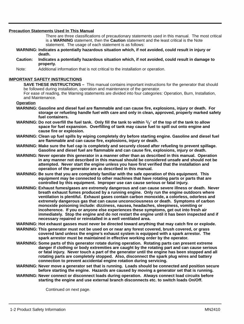
IMPORTANT SAFETY INSTRUCTIONSSAVE THESE INSTRUCTIONS – This manual contains important instructions for the generator that shouldbe followed during installation, operation and maintenance of the generator.For ease of reading, the Warning statements are divided into four categories: Operation, Burn, Installation,and Maintenance.
OperationWARNING: Gasoline and diesel fuel are flammable and can cause fire, explosions, injury or death. For
storage or refueling handle fuel with care and only in clean, approved, properly marked safetyfuel containers.
WARNING: Do not overfill the fuel tank. Only fill the tank to within 1/2� of the top of the tank to allowspace for fuel expansion. Overfilling of tank may cause fuel to spill out onto engine andcause fire or explosion.
WARNING: Clean up fuel spills by wiping completely dry before starting engine. Gasoline and diesel fuelare flammable and can cause fire, explosions, injury or death.
WARNING: Make sure the fuel cap is completely and securely closed after refueling to prevent spillage.Gasoline and diesel fuel are flammable and can cause fire, explosions, injury or death.
WARNING: Never operate this generator in a manner other than as described in this manual. Operationin any manner not described in this manual should be considered unsafe and should not beattempted. Never start the engine unless you have first verified that the installation andoperation of the generator are as described in this manual.
WARNING: Be sure that you are completely familiar with the safe operation of this equipment. Thisequipment may be connected to other machines that have rotating parts or parts that arecontrolled by this equipment. Improper use can cause serious or fatal injury.
WARNING: Exhaust fumes/gases are extremely dangerous and can cause severe illness or death. Neverbreath exhaust fumes produced by a running engine. Only run the engine outdoors whereventilation is plentiful. Exhaust gases contain carbon monoxide, a colorless, odorless andextremely dangerous gas that can cause unconsciousness or death. Symptoms of carbonmonoxide poisoning include: dizziness, nausea, headaches, sleepiness, vomiting orincoherence. If you or anyone else experiences these symptoms, get out into fresh airimmediately. Stop the engine and do not restart the engine until it has been inspected and ifnecessary repaired or reinstalled in a well ventilated area.
WARNING: Hot exhaust gasses must never be directed toward anything that may catch fire or explode.WARNING: This generator must not be used on or near any forest covered, brush covered, or grass
covered land unless the engine’s exhaust system is equipped with a spark arrestor. Thespark arrestor must be maintained in effective working order by the operator.
WARNING: Some parts of this generator rotate during operation. Rotating parts can present extremedanger if clothing or body extremities are caught by the rotating part and can cause seriousor fatal injury. Never touch a part of the generator until the engine has been stopped and allrotating parts are completely stopped. Also, disconnect the spark plug wires and batteryconnection to prevent accidental engine rotation during servicing.
WARNING: Never move a generator set that is running. Loads should be connected and position securebefore starting the engine. Hazards are caused by moving a generator set that is running.
WARNING: Never connect or disconnect loads during operation. Always connect load circuits beforestarting the engine and use external branch disconnects etc. to switch loads On/Off.
Continued on next page.

Product Safety Information 1-3MN2410
Operation Warning Statements ContinuedWARNING: Be sure that you understand how to stop the engine quickly in case of an emergency
situation. Become familiar with the controls and safety systems provided with this generatorset.
WARNING: Always wear safety glasses with side shields and hearing protection when working near thegenerator.
WARNING: Improper operation may cause violent motion of connected equipment. Be certain thatunexpected movement will not cause injury to personnel or damage to equipment.
WARNING: Never operate the generator set indoors or in a poorly ventilated area such as a tunnel orcave. Exhaust fumes are extremely dangerous to all personnel that are in or in contact withthat area.
WARNING: Never permit anyone to operate the generator without proper instructions. Be sure to keep acopy of this manual with the generator so that all users can be properly informed of its safeoperation.
WARNING: Never allow children or pets to be in the area where the generator is running. The generatorand the equipment being powered by the generator may cause injury or death.
WARNING: Never operate the generator unless all guards, covers, shields and other safety items areproperly installed.
WARNING: Do not put hands, feet, tools clothing or other objects near rotating parts such as drive shaft,pulley, belt etc. Rotating parts cause extremely dangerous situations because they can catchloose clothing or extremities and cause serious or fatal injury.
WARNING: When operating this generator remain alert at all times. Never operate machinery whenphysically or mentally fatigued, or while under the influence of alcohol, drugs or medication.
WARNING: Never operate the engine when the air cleaner is removed. An engine backfire can causeserious burns.
WARNING: Never “jump start” a generator to start the engine. If the battery charge is insufficient to startthe engine, charge or replace the battery and try to restart. Jump starting a battery can causethe battery to explode and cause severe injury or death to anyone in the area.
WARNING: High voltage is present whenever engine is running. Electrical shock can cause serious orfatal injury. Never operate electrical equipment while standing in water, on wet ground or withwet hands, feet or shoes or while barefoot.
WARNING: High voltage is present whenever the engine is running. Electrical shock can cause seriousor fatal injury. Always stop engine before connecting or disconnecting power cords orexternal devices.
WARNING: Do not smoke near generator during operation or while refueling. Gasoline and diesel fuel areflammable and can cause fire, explosions, injury or death.
WARNING: Stop engine and allow engine to cool before refueling. Gasoline and diesel fuel are flammableand can cause fire, explosions, injury or death.
WARNING: Never store the generator with fuel in the tank. Never store the generator indoors or in anenclosed area or in a poorly ventilated enclosure where fumes may reach an open flame,electrical spark or pilot light as on a furnace, water heater, clothes dryer, etc. Gasoline anddiesel fuel are flammable and can cause fire, explosions, injury or death.
WARNING: Allow generator to cool before transporting it or storing it. Always drain fuel from tank aftergenerator has cooled.
WARNING: When transporting the generator (especially over rough roads) always drain the fuel tank toprevent leakage or spillage of fuel. Gasoline and diesel fuel are flammable and can cause fire,explosions, injury or death.
WARNING: Operate the generator only on a level surface. If the generator is tilted during operation, fuelspillage may result. Gasoline and diesel fuel are flammable and can cause fire, explosions,injury or death.
WARNING: Keep generator at least three feet away from buildings and other structures.WARNING: Keep generator away from flammable or hazardous materials (trash, rags, lubricants,
explosives, paints etc.) and grass or leaf build up.WARNING: Keep a fire extinguisher near the generator while generator is in use. An extinguisher rated
“ABC” by the National Fire Protection Association is appropriate.
Continued on next page.
1-4 Product Safety Information MN2410
Warning Statements ContinuedBurnWARNING: Parts of this generator are extremely hot during and after operation. To prevent severe burns,
do not touch any part of the generator until you have first determined if the part is hot. Wearprotective clothing and after use allow sufficient time for parts to cool before touching anypart of the generator.
WARNING: Do not touch the hot exhaust parts or the high voltage spark plug or coil terminals of theengine. Although spark plug voltages are not normally lethal, a sudden involuntary jerk of thehand or body part caused by contact with high voltage or a hot surface can result in injury toyourself or others.
InstallationWARNING: Installation and repair procedures requires specialized skills with electrical generating
equipment and small engine systems. Any person that installs or performs repairs must havethese specialized skills to ensure that the generator set is safe to operate. Contact Baldor forinstallation or repairs.
WARNING: Be sure all wiring complies with the National Electrical Code (NEC) and all regional and localcodes or CE Compliance. Improper wiring may cause a hazardous condition and exposure toelectrical hazards can cause serious injury or death.
WARNING: Be sure the system is properly grounded before applying power. Do not apply AC powerbefore you ensure that grounds are connected. Electrical shock can cause serious or fatalinjury. NEC requires that the frame and exposed conductive surfaces (metal parts) beconnected to an approved earth ground. Local codes may also require proper grounding ofgenerator systems.
WARNING: Place protective covers over all rotating parts such as drive shaft, pulley, belt etc. Rotatingparts cause extremely dangerous situations because they can catch loose clothing orextremities and cause serious or fatal injury.
WARNING: Unauthorized modification of a generator set may make the unit unsafe for operation or mayimpair the operation of the unit. Never start a generator set that has been modified ortampered with. Be sure that all covers and guards are properly installed and that the unit issafe before starting the engine. If you are unsure, contact Baldor before starting the engine.
WARNING: When moving the generator, use reasonable caution. Be careful where you place fingers andtoes to prevent injury “Pinch Points”. Never try to lift a generator without a hoist or lift meansbecause they are heavy and bodily injury may result.
WARNING: When transporting a generator (especially if it has wheel option installed) secure the unit toprevent movement during transport.
WARNING: Never connect this generator to any buildings electrical system unless a licensed electricianhas installed an approved transfer switch. The National Electrical Code (NEC) requires thatconnection of a generator to any electrical circuit normally powered by means of an electricutility must be connected by means of approved transfer switch equipment so as to isolatethe electrical circuit from the utility distribution system when the generator is operating.Failure to isolate the electrical circuits by such means may result in injury or death to utilitypower workers due to backfeed of electrical energy onto the utility lines.
WARNING: Circuit overload protection must be provided in accordance with the National Electrical Codeand local regulations.
WARNING: Check Ground Fault Circuit Interrupt (GFCI) receptacles monthly by using the “Test” and“Reset” buttons.
WARNING: Only a professional experienced technician should install a fuel supply system. Gasoline anddiesel fuel are flammable and can cause fire, explosions, injury or death. Fuel supply linesshould be kept away from sharp objects to prevent rupture. Comply with all NFPA regulationsand local codes for shut–off valves, regulators, fuel line type etc.
WARNING: Have electrical circuits and wiring installed and checked by licensed electrician or qualifiedtechnician. Electrical shock can cause serious or fatal injury.
WARNING: Incorrect installation of this generator set could result in property damage, injury or death.Connection of the generator to its fuel source must be done by a qualified professionaltechnician or contractor.
Continued on next page.

Product Safety Information 1-5MN2410
Warning Statements ContinuedMaintenanceWARNING: Before cleaning, inspecting, repairing, refueling or performing any maintenance to the
generator set, always be sure the engine has stopped and that all rotating parts have alsostopped. After stopping, certain components are still extremely hot so be careful not to getburned. Before servicing the generator set, be sure to disconnect the spark plug wires andthe battery terminals to prevent accidental engine rotation or starting.
WARNING: Engine coolant is under pressure and is near the boiling point of water when engine is hot.Do not open the coolant system until the engine has completely cooled. Hot coolant cancause severe burns and other injuries. When engine is cool, coolant level can be checked.
WARNING: Before servicing the generator set, be sure to disconnect the spark plug wires and the batteryterminals to prevent accidental engine rotation or starting.
WARNING: Inspect all wiring frequently and replace any damaged, broken or frayed wiring or wires withdamaged insulation immediately. Electrical shock can cause serious or fatal injury.
WARNING: Disconnect all electrical wires and load devices from generator power outlets before servicingthe generator. Electrical shock can cause serious or fatal injury. Always treat electricalcircuits as if they are energized.
WARNING: Check all fuel tanks, supply piping, and their connections monthly for fuel leaks. Gasolineand diesel fuel are flammable and can cause fire, explosions, injury or death. If a leak isfound, replace only with approved pipe or components.
WARNING: A battery presents a risk of fire and explosion because they generate hydrogen gas.Hydrogen gas is extremely explosive. Never jump start a battery, smoke in the area aroundthe battery or cause any spark to occur in the area around the battery.
WARNING: Do not mutilate the battery or dispose of a battery in a fire. The battery is capable ofexploding. If the battery explodes, electrolyte solution will be released in all directions.Battery electrolyte solution is caustic and can cause severe burns and blindness. Ifelectrolyte contacts skin or eyes, immediately flush the area with water and seek medicalattention quickly.
WARNING: A battery presents a risk of electrical shock hazard and high short circuit current. Electricalshock can cause serious or fatal injury. Never wear jewelry, watch or any metal objects whenin the area around the battery.
WARNING: The battery electrolyte is a dilute sulfuric acid that is harmful to the skin and eyes. It iselectrically conductive and corrosive. If electrolyte contacts the skin, flush the areaimmediately with water and wash it off using soap and water. If electrolyte contacts the eyes,immediately flush the eye thoroughly with water and seek medical attention quickly.
WARNING: The capacitor used in this generator can store and discharge a high voltage charge. Beforeworking with or in the area of the capacitor, discharge the capacitor by shorting its leadstogether with a screwdriver with an insulated handle or insulated jumper wire.
WARNING: Be extremely careful when flashing the generator. When the alternator cover is removedrotating parts and high voltage are present. Electrical shock can cause serious or fatal injury.Rotating parts can present extreme danger if clothing or body extremities are caught by therotating part and can cause serious or fatal injury.
WARNING: Never store an engine with fuel in its tank indoors or in an enclosed, poorly ventilated areawhere gasoline fumes could reach an ignition source and cause an explosion.
Continued on next page.

1-6 Product Safety Information MN2410
Caution StatementsCaution: The brass connecting tab on some 120VAC duplex receptacles have been removed. Each
receptacle is powered by a separate generator winding. When replacing a receptacle, inspectthe brass tab that normally links both receptacles. If it is removed, be sure to remove thebrass tab from the replacement receptacle before it is installed. Failure to remove the tab willcause a direct short to the generator windings and cause possible generator damage.
Caution: Avoid installing the generator set beside heat generating equipment, or directly below wateror steam pipes or in the vicinity of corrosive substances or vapors, metal particles and dust.Heat can cause engine problems to develop and unwanted substances can cause rust orgenerator failure over time.
Caution: Do not apply high voltage to windings in a moisture–saturated condition. Moisture can causeinsulation breakdown, making it necessary to return the generator to the factory for repair,and consequent expense and loss of time.
Caution: Use only original equipment or authorized replacement parts. Using the correct parts willassure continued safe operation as designed.
Caution: Do not support the generator from the top of the wrap frame.Caution: Do not tamper with or change the engine speed. Engine speed is factory set to produce the
correct voltage and output frequency.Caution: Never operate the engine without a muffler. The engine is designed to have the correct
exhaust components installed and operating without these components can present a firehazard, cause excessive exhaust gases and cause damage to engine. Inspect mufflerperiodically and replace if necessary.

Section 2General Information
General Information 2-1MN2410
This manual contains information you need to safely and efficiently operate your generator set.During the preparation of this manual every effort was made to ensure the accuracy of itscontents. This manual describes only very basic engine information. A separate owner’s manualfor the engine is supplied with this unit for your use. Please refer to the engine manual forinformation relative to engine operation, maintenance, recommendations and additional safetywarnings.Baldor Generators (formerly Pow’R Gard Generator Corporation) has been in business since1965. The generator sets we manufacture have earned the reputation of being high quality anddependable. We take pride in this fact and continue to keep our quality standards high on our listof priorities. We are also constantly researching new technological ideas to determine if theycould be used to make our generator sets even better.Thank you for purchasing your Baldor Generator Set.Copyright Baldor 2003. All rights reserved.This manual is copyrighted and all rights are reserved. This document may not, in whole or inpart, be copied or reproduced in any form without the prior written consent of Baldor ElectricCompany, Inc.Baldor makes no representations or warranties with respect to the contents hereof andspecifically disclaims any implied warranties of fitness for any particular purpose. The informationin this document is subject to change without notice. Baldor assumes no responsibility for anyerrors that may appear in this document.
Limited Warranty
Unless otherwise provided, Baldor generators are warranted against defects in Baldor workmanship andmaterials for a period of time as set forth in the Warranty Period chart below. If a Baldor product is defective due toBaldor workmanship or materials and the defect occurs during the warranty period, then Baldor will either repairthe product or replace it with a new one, whichever Baldor believes to be appropriate under the circumstances.Service for warranty issues regarding any Baldor Generators Products Warranty is available by contacting BaldorGenerators’ Customer Service Department in Oshkosh, Wisconsin. A list of Baldor’s generator repair facilitiesmay be obtained by contacting Baldor Generators at: Customer Service, Baldor Generators, 3815 OregonStreet, Oshkosh, Wisconsin 54902, 920–236–4200 (telephone), 920–236–4219 (facsimile). All Baldor productsrequiring warranty service shall be transported or shipped freight pre–paid, at the risk of the party requiringwarranty service, to a Baldor Generator repair facility, or to Baldor Generators’ Customer Service Department inOshkosh, Wisconsin. Written notification of the alleged defect in addition to a description of the manner in whichthe Baldor generator is used, and the name, address and telephone number of the party requiring warrantyservice must be included. Baldor is not responsible for removal and shipment of the Baldor product to the servicecenter or for the reinstallation of the Baldor product upon its return to the party requiring warranty service.Customers who are unable to take or ship the Baldor product to a Baldor Generator repair facility, or who desire arepair to be made by other than a Baldor Generator repair facility, should contact Baldor Generators’ CustomerService Department at 920–236–4200. Baldor, in advance of such service, must approve a repair by anyoneother than a Baldor Generator repair facility in writing. Problems with Baldor products can be due to impropermaintenance, faulty installation, non–Baldor additions or modifications, or other problems not due to defects inBaldor workmanship or materials. If a Baldor Generator repair facility determines that the problem with a Baldorproduct is not due to defects in Baldor workmanship or materials, then the party requesting warranty service willbe responsible for the cost of any necessary repairs. Parties requiring warranty service not satisfied with adetermination that a problem is outside of warranty coverage should contact Baldor Generators’ CustomerService Department at 920–236–4200 for further consideration. EXCEPT FOR THE EXPRESSED WARRANTYSET FORTH ABOVE, BALDOR GENERATORS DISCLAIMS ALL OTHER EXPRESSED AND IMPLIEDWARRANTIES INCLUDING THE IMPLIED WARRANTIES OF FITNESS FOR A PARTICULAR PURPOSE ANDMERCHANTABILITY. NO OTHER WARRANTY, EXPRESSED OR IMPLIED, WHETHER OR NOT SIMILAR INNATURE TO ANY OTHER WARRANTY PROVIDED HEREIN, SHALL EXIST WITH RESPECT TO THE GOODSSOLD UNDER THE PROVISIONS OF THESE TERMS AND CONDITIONS. ALL OTHER SUCH WARRANTIESARE HEREBY EXPRESSLY WAIVED BY THE BUYER. UNDER NO CIRCUMSTANCES SHALL BALDORGENERATORS BE LIABLE OR RESPONSIBLE IN ANY MANNER WHATSOEVER FOR ANY INCIDENTAL,CONSEQUENTIAL OR PUNITIVE DAMAGES, OR ANTICIPATED PROFITS RESULTING FROM THEDEFECT, REMOVAL, REINSTALLATION, SHIPMENT OR OTHERWISE. This is the sole warranty of BaldorGenerators and no other affirmations or promises made by Baldor Generators shall be deemed to create anexpressed or implied warranty. Baldor Generators has not authorized anyone to make any representations orwarranties other than the warranty contained herein.

2-2 General Information MN2410
Limited Warranty Continued
Warranty Period
Generator Series Labor* PartsPortable Products
(Premier, Powerchief, DG Series, K Series)1 Year 3 Years
Towable Products (TS) 1 Year or 3,000 HoursWhichever comes first
3 Years or 3,000 HoursWhichever comes first
3600 RPM Standby Systems(Some AE Models)
1 Year or 1,000 HoursWhichever comes first
3 Years or 1,000 HoursWhichever comes first
1800 RPM Standby Systems(Some AE Models, DLC, GLC)
1 Year or 3,000 HoursWhichever comes first
3 Years or 3,000 HoursWhichever comes first
Industrial Standby Systems 1 Year or 1,000 HoursWhichever comes first
2 Years or 1,000 HoursWhichever comes first
Industrial Prime Power Systems 1 Year or 1,000 HoursWhichever comes first
1 Year or 1,000 HoursWhichever comes first
International 1 Year or 1,000 HoursWhichever comes first
1 Year or 1,000 HoursWhichever comes first
Notes for Warranty Period:1. Labor coverage for warrantable repairs is provided for the applicable period not to
exceed published rates as contained in the Baldor Generators Warranty Policy.Mileage is allowed only for permanent installations not to exceed published rates ascontained in the Baldor Generators Warranty Policy.
2. Proof of purchase date is required for all Portable and Towable products to qualify forany warranty consideration. Serial number and model number will be required for allwarranty work.
3. For all other products, a Start–up Inspection Form / Warranty Registration must becompleted in its entirety and submitted to Baldor Generators within 30 days of start–upto qualify for any warranty consideration.
Owner’s ResponsibilitiesThe owner is obligated to operate and maintain the generator in accordance with therecommendations published by Baldor Generators in the Operator’s Manual for the generator.The owner is responsible for the costs associated with maintenance and any adjustments thatmay be required.The owner is responsible for payment of any of the following expenses that might be incurred asa result of a failure under the terms of this warranty:
1. Rental equipment used to replace the equipment being repaired.2. Telephone or other communication expenses.3. Living and travel expenses of persons performing service, except as specifically included
within the terms of specific warranty.4. The premium costs for overtime labor requested by the owner.5. All parts transportation costs.
All warranty claims must be submitted to a Baldor Generator repair facility prior to the expirationof the warranty period. Baldor Generators shall have no responsibility or liability for any defect,latent or otherwise, discovered after the expiration of the warranty period provided herein.Extended warranties are available for certain Baldor products. These warranties are described inBaldor’s catalog and other sales literature. Extended warranties are subject to the terms andconditions of this Limited Warranty as modified by the additional terms of the extended warranty.
LimitationsBaldor Generators is not responsible for the repair of generators required because of normalwear, accident, misuse, abuse, improper installation, lack of maintenance, unauthorizedmodifications or improper storage.Normal Wear: This warranty will not cover repair where normal use has exhausted the life of apart or generator. It should be remembered that the service life of any generator is dependent onthe care it receives and the conditions under which it has to operate. Some applications are veryoften used in dusty or dirty conditions, which can cause what appears to be excessive wear.Such wear, when caused by dirt, dust, grit or other abrasive material, which has entered thegenerator because of improper maintenance, is not covered by Warranty.For all product lines, the engine manufacturer warrants engine systems. Contact Baldor Generators for current engine warranties.

Section 3Receiving & Installation
Receiving & Installation 3-1MN2410
Receiving & Inspection When you receive your generator, there are several things you should do immediately.1. Observe the condition of the shipping container and report any damage immediately to
the commercial carrier that delivered your system.2. Verify that the part number of the system you received is the same as the part number
listed on your purchase order.3. If the system is to be stored for several weeks before use, be sure that it is stored in a
location that conforms to published storage temperature and humidity specifications.(Refer to Section 9 of this manual).
Lifting the GeneratorWhen lift or hoist equipment is used to lift the generator and move it to position, be careful not tocontact overhead wires or other obstacles. The generator weighs between 100 and 300 lbs.Use proper lift equipment and methods to avoid injury. Lift only by the tubular metal frame.
Figure 3-1 Premier Generators
Storage If you will not be using the generator set for a significant amount of time (3 months or longer) youshould store the generator to prevent any problems that could arise from sitting idle. Please fullyread the following guidelines prior to storing the unit.
1. Remove all fuel from the engine’s fuel tank.2. Start the generator set and allow it to run out of fuel.3. Close all the fuel valves.
Note: An alternative to draining the fuel from a gasoline engine is adding a fuel stabilizer, tominimize the formation of fuel gum deposits during storage (Follow the manufacturer’sdirections). After the fuel stabilizer is added, run the generator set for 5 minutes to get thestabilizer into the carburetor. After shutting the engine off, be sure to close all the fuelvalves.
4. Disconnect and remove the battery if your generator set is so equipped.5. Drain the used oil from the engine’s crankcase and refill it with clean oil.6. Remove the spark plugs and pour1 oz. of clean engine oil into each cylinder. Put a rag
over each spark plug port and turn the engine over approximately 5 times to distributethe oil in the cylinder.
7. Replace the spark plug(s) but do not connect the plug wires. This will help preventaccidental or unauthorized starting.
8. Provide maintenance to the engine and generator set as described in the engine andgenerator maintenance sections of this manual.
9. Cover any bare metal spots with paint or another type of rust preventative.WARNING: Never store an engine with fuel in its tank indoors or in an enclosed, poorly ventilated area
where gasoline fumes could reach an ignition source and cause an explosion.

3-2 Receiving & Installation MN2410
Physical LocationThe mounting location of the system is important. It should be installed in an area that isprotected from direct harmful gases or liquids, dust, metallic particles, shock and vibration. It canonly be installed in an outdoor location so the exhaust fumes are vented to the atmosphere. Thissystem must never be installed inside an enclosed building, home, shop or garage etc.Several other factors should be carefully evaluated when selecting a location for installation:
1. For effective cooling and maintenance, the generator should be mounted on a flat, smooth,non-flammable level surface. A concrete pad is ideal and provides a secure installation.
2. The location for the generator must be dry. Never operate a generator in an area thathas standing water or puddles.
3. Installation should prevent obstructions by buildup of leaves, grass, sand, snow, etc. Itis important that the unit be operated in a reasonably clean environment.
4 All engines give off considerable heat when running. The engine in your generator setuses air to keep it cool so it is important that the ambient temperature is cool and doesnot exceed 100°F (even while it is running). Where natural ventilation is inadequate afan to boost circulation should be used.
5. Exhaust Gases from internal combustion engines are extremely poisonous. Neveroperate an engine indoors.
WARNING: Exhaust fumes/gases are extremely dangerous and can cause severe illness or death. Neverbreath exhaust fumes produced by a running engine. Only run the engine outdoors whereventilation is plentiful. Exhaust gases contain carbon monoxide, a colorless, odorless andextremely dangerous gas that can cause unconsciousness or death. Symptoms of carbonmonoxide poisoning include: dizziness, nausea, headaches, sleepiness, vomiting orincoherence. If you or anyone else experiences these symptoms, get out into fresh airimmediately. Stop the engine and do not restart the engine until it has been inspected and ifnecessary repaired or reinstalled in a well ventilated area.
6. All electrical equipment should be protected from excessive moisture. Failure to do sowill result in deterioration of the insulation and may result in short circuits and apossible electrocution hazard.
Installation The generator is completely assembled, tested and adjusted at the factory before it is shipped toyou. External connections required at the time of installation are:Note: The generator is shipped dry. This means no oil is in the engine crankcase and no battery
is installed. You must refer to the engine manual and obtain the correct type and quantityof engine motor oil and the correct battery (if equipped for electric start).
1. Electrical Connections.2. Ground Connection.
After installation, the post installation checks must be performed prior to starting the engine.After these checks have been performed and the system operation is verified to be good, refer toSection 6 Maintenance for periodic checks that must be performed at scheduled intervals toensure continued operation with minimal problems.
Electrical Connections All load connections are made at the panel using electrical cords with the propermating plug for the receptacle being used. More than one receptacle can be used as long as thetotal load does not exceed the continuous rating of the generator.
WARNING: Never connect this generator to any buildings electrical system unless a licensed electricianhas installed an approved transfer switch. The National Electrical Code (NEC) requires thatconnection of a generator to any electrical circuit normally powered by means of an electricutility must be connected by means of approved transfer switch equipment so as to isolatethe electrical circuit from the utility distribution system when the generator is operating.Failure to isolate the electrical circuits by such means may result in injury or death to utilitypower workers due to backfeed of electrical energy onto the utility lines.
Use correct size insulated wire to connect the generator to the load. The gauge of the wire willdepend on the distance to the load, the permissible voltage drop at the load, and the currentrequired by the load. If you are not sure of the gauge wire needed for your application, consult acompetent electrician. Using wire that is too small can result in fire hazard. Also, be sure thewire has the appropriate ratings for insulation and environment conditions.The correct mating connector must be used to fit the connectors provided on the operator panelof your generator. Table 3-1 describes the connector types provided (receptacles) and the loadcharacteristics to help you choose the correct size wire. Figure 3-2 shows the receptacles.
Receiving & Installation 3-3MN2410
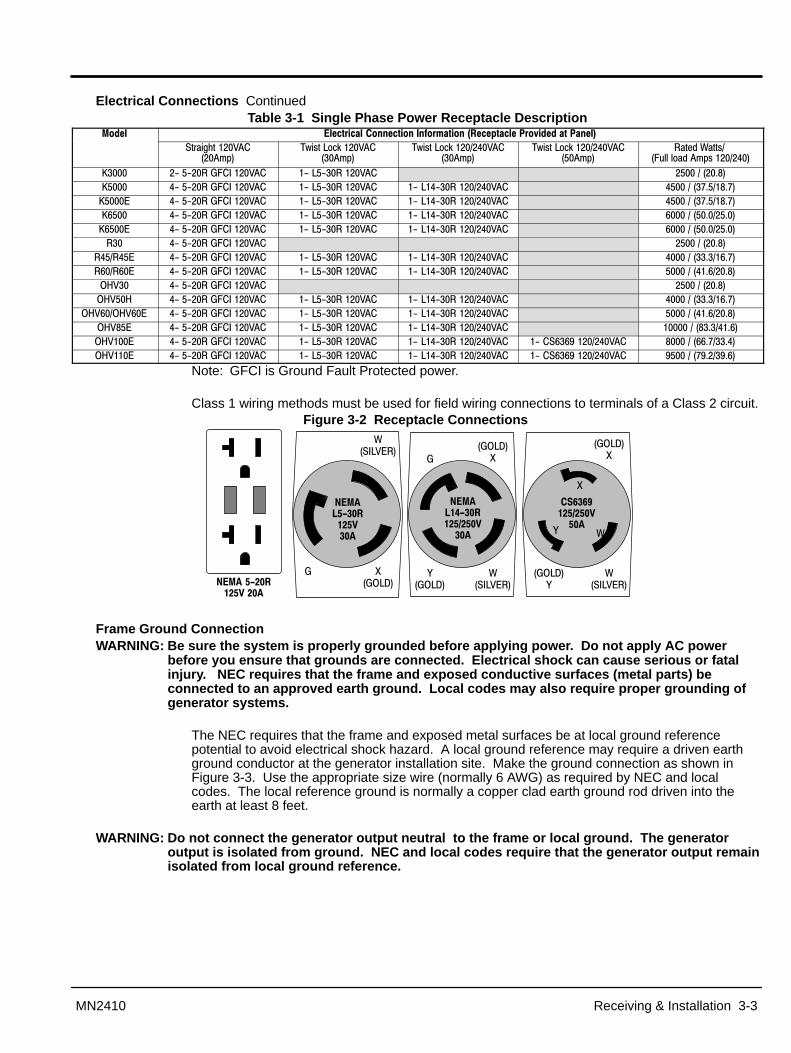
Electrical Connections ContinuedTable 3-1 Single Phase Power Receptacle Description
����� ��������� �����������������������������������������������
����������� ��� ���
������������� ���� ���
���������������� ���� ���
���������������� ���� ���
���� �!�������"#$$�$�� � ���������
%���� &��&���'"�(��� � &���&������ � ��������)*�%���� �&��&���'"�(��� � &���&������ � &���&��������� � ���������+)��*)+�%����, �&��&���'"�(��� � &���&������ � &���&��������� � ���������+)��*)+�%-��� �&��&���'"�(��� � &���&������ � &���&��������� � -���������)���)��%-���, �&��&���'"�(��� � &���&������ � &���&��������� � -���������)���)����� �&��&���'"�(��� � ��������)*�
�������, �&��&���'"�(��� � &���&������ � &���&��������� � ����������)��-)+��-���-�, �&��&���'"�(��� � &���&������ � &���&��������� � ���������)-��)*�./��� �&��&���'"�(��� � ��������)*�./���/ �&��&���'"�(��� � &���&������ � &���&��������� � ����������)��-)+�
./�-��./�-�, �&��&���'"�(��� � &���&������ � &���&��������� � ���������)-��)*�./�*�, �&��&���'"�(��� � &���&������ � &���&��������� � ��������*�)���)-�./���, �&��&���'"�(��� � &���&������ � &���&��������� � &���-�-0������ � *�������--)+���)��./��, �&��&���'"�(��� � &���&������ � &���&��������� � &���-�-0������ � 0�������+0)��0)-�
Note: GFCI is Ground Fault Protected power.
Class 1 wiring methods must be used for field wiring connections to terminals of a Class 2 circuit.Figure 3-2 Receptacle Connections
1�'.�2�
'
!��(��,��
����������� �!���
�'.�2�1'
!��(��,��
3�'.�2�
������"����� �# ��!
���
�'.�2�1
!��(��,��
�'.�2�3
$%�%&� �# ��!
���
1
3 !
������� ��� �!� ��
Frame Ground ConnectionWARNING: Be sure the system is properly grounded before applying power. Do not apply AC power
before you ensure that grounds are connected. Electrical shock can cause serious or fatalinjury. NEC requires that the frame and exposed conductive surfaces (metal parts) beconnected to an approved earth ground. Local codes may also require proper grounding ofgenerator systems.
The NEC requires that the frame and exposed metal surfaces be at local ground referencepotential to avoid electrical shock hazard. A local ground reference may require a driven earthground conductor at the generator installation site. Make the ground connection as shown inFigure 3-3. Use the appropriate size wire (normally 6 AWG) as required by NEC and localcodes. The local reference ground is normally a copper clad earth ground rod driven into theearth at least 8 feet.
WARNING: Do not connect the generator output neutral to the frame or local ground. The generatoroutput is isolated from ground. NEC and local codes require that the generator output remainisolated from local ground reference.

3-4 Receiving & Installation MN2410
Frame Ground Connection ContinuedFigure 3-3 Frame Ground Connection
Earth Ground
Frame
Stud
WasherGround Wire Lug
Nut
Washer
Engine Oil Refer to the engine manual that was provided with your generator. Determine the correct type ofengine oil and the amount specified by the engine manufacturer. Add the required amount of oilto bring the oil level to full.
Battery Connections Applies to 12VDC Electric Start models only.The generator is shipped with no battery installed.
WARNING: Do not dispose of battery or batteries in a fire. The battery is capable of exploding. If thebattery explodes, electrolyte solution will be released in all directions. Battery electrolytesolution is caustic and can cause severe burns and blindness. If electrolyte contacts skin oreyes, immediately flush the area with water and seek medical attention quickly.
WARNING: Do not mutilate the battery . The battery contains electrolyte solution which is caustic andcan cause severe burns and blindness. If electrolyte contacts skin or eyes, immediately flushthe area with water and seek medical attention quickly.
WARNING: A battery presents a risk of electrical shock hazard and high short circuit current. Thefollowing precautions are to be followed when working on batteries:
1. Remove watches, rings, necklaces and all other metal objects.2. Use tools with insulated handles.3. Wear rubber gloves and boots.
WARNING: The battery electrolyte is a dilute sulfuric acid that is harmful to the skin and eyes. It iselectrically conductive and corrosive. The following precautions are to be followed whenworking on batteries:
1. Wear full eye protection (safety glasses or goggles) and protective clothing.2. Where electrolyte contacts the skin, flush the area immediately with water and wash it
off using soap and water.3. Where electrolyte contacts the eyes, immediately flush the eye thoroughly with water
and seek medical attention quickly.4. Spilled electrolyte is to be washed down with an acid neutralizing agent. A common
practice is to use a solution of one pound (500 grams) bicarbonate of soda to onegallon (four liters) of water. the bicarbonate solution is to be added until evidence ofreaction (foaming) has ceased. The resulting liquid is to be flushed with water and thearea dried.
WARNING: A battery presents a risk of fire because they generate hydrogen gas. Hydrogen gas isextremely explosive. Never jump start a battery, smoke in the area around the battery orcause any spark to occur in the area around the battery. The following precautions are to befollowed when working on batteries:
1. Do not smoke when near batteries.2. Do not cause flame or spark in battery area.3. Discharge static electricity from body before touching batteries by first touching a
grounded metal surface.

Receiving & Installation 3-5MN2410
Battery Connections ContinuedProcedure: The correct type battery must be purchased and installed in the battery compartment provided.
1. Remove the bag containing the battery box components.2. Set the battery on the battery tray.3. Install the battery hold down rods as shown in Figure 3-4.
a. Place the bent end of the battery hold down rod through the hole in the batterytray.
b. Place the threaded end of the battery hold down rod through the hole in thebattery hold down bar and secure with flat washer, lock washer and nut.
c. Repeat steps a and b for the other battery hold down rod.4. Connect the battery cables to the battery, be sure the Positive lead is connected to the
positive (+) battery terminal and the negative lead is connected to the positive (–)battery terminal.
Figure 3-4 Battery Installation
Washers & Nut
Battery
Battery Tie Down Bolt
Washers & Nut
Battery Rack
Battery Tie Down
The + and – terminals of your battery maybe different than shown. Be sure that thePositive lead is connected to the positive(+) terminal of your battery.
Use of Electric Motor LoadsElectric motors require much more current (amperes) to start them than to keep them running.Some motors, particularly split–phase motors are very difficult to start and require 5 to 7 timesmore current to start them. Repulsion–induction type motors are the easiest to start and normallyonly require 2 to 3 times as much current to start them.Most fractional horsepower motors take about the same amount of current to start them andkeep them running. This is true whether they are the repulsion–induction type motor, capacitortype motor, or the split–phase type motor.Other factors that influence the amount of current needed to start a motor are:
1. The type of load connected to the motor. If the electric motor is connected to a hardstarting load such as an air compressor it will require more starting current. If the sameelectric motor is connected to a light load such as a heater or power saw it will requireless starting current.
2. The brand or design of the electric motor. The expected starting current for aparticular size motor will vary depending on the brand of the electric motor as well asthe type of electric motor (Split Phase, capacitor, Repulsion–induction type, etc.)
3. The condition of the electric motor. A clean motor with free turning bearings willrequire less starting currents than a similar type motor that is dirty and the bearings arenot as free turning as they used to be.

3-6 Receiving & Installation MN2410
Optional Wheel Kit PDG2 – 2 Wheel Dolly Kit; and PDG4 – 4 Wheel Dolly KitAn optional 2 or 4 wheel dolly kit is available for Premier portable generators. If you havepurchased one of these kits, refer to MN2409 for the installation instructions.
Recommended Engine Oil and Battery Type$��'�(
�)*��$+���� ,��-�� )�� �� )����*�* ����$�� )�*
�)*��$+����
)��,��-��
)��)��
��� �-.�� )����*�*
/�--��.����$�� )�* ���(��0
%������)����� � ,)��� �!��� �)��4�� 5� 5� %������)����� � ,)��� �!��� �)+�4�� 5� 5� %-�����)���� � ,)��� �!��� �)+��4�� 5� 5� %����,��)���� � ,)��� �!��� �)+��4�� 3��&5*�& � ���%-���,��)����� � ,)��� �!��� �)+��4�� 3��&5*�& � ���$��'��
�)*��$+���� ,��-�� )�� �� )����*�* ����$�� )�*
�)*��$+����
)��,��-��
)��)��
��� �-.�� )����*�*
/�--��.����$�� )�* ���(��0
���&�)��� � ,)��� �!��� )��4�� 5� 5� ���&�)��� � ,)��� �!��� )-��4�� 5� 5� �-�&�)�-� � ,)��� �!��� )0��4�� 5� 5� �-�,&�)�- � ,)��� �!��� )0��4�� 6�(�-&6 ���
$��'�)1!
�)*��$+���� ,��-�� )�� �� )����*�* ����$�� )�*
�)*��$+����
)��,��-��
)��)��
��� �-.�� )����*�*
/�--��.����$�� )�* ���(��0
./���&�)���� � ,)��� �!��� �)*��4�� 5� 5�
./���&�)�� � ,)��� �!��� �)��4�� 5� 5�
./���&�)��� � ,)��� �!��� �)���4�� 5� 5�
./���,&�)��- � ,)��� �!��� �)���4�� (7����������4&�� ���
./���/&�)��� � ,)��� �!��� �)0��4�� 5� 5�
./�-�&�)��+ � ,)��� �!��� �)��4�� 5� 5�
./�-�,&�)��0 � ,)��� �!��� �)��4�� (7����������4&�� ���
./�*�,&�)��+� � ,)��� �!��� �)��4�� (7����������4&�� ���
./���,&�)��0� � ,)��� �!��� �)��4�� (7����������4&�� ���
./��,&�)�� � ,)��� �!��� �)���4�� (7����������4&�� ���

Section 4Operation
Operation 4-1MN2410
Operator Control PanelEach operator panel is slightly different, depending on features of the generator you purchased.The Operator Control Panel of Figure 4-1 is shown because it has most of the available features.This will be used to explain how the controls operate.
Figure 4-1 Operator Control Panel
Auto Idler Off – The engine will run continuously at the predetermined speed set by the governor.ON – Allows the engine to run at slow speed when there is no electrical load. When anelectrical load is applied, the Auto Idler control changes the engine speed to thepredetermined speed set by the governor.
Elapsed Time An hour meter that measures the total hours the generator has been in use (enginerunning).
AC Voltmeter Displays the voltage level at the output of the generator (the 230VAC output).AC Circuit Breakers Provide overcurrent protection for the generator output. When tripped, the plunger (in
center of breaker) will extend out about 3/8 inch. Remove the loads, push the plungerinto the breaker to reset the breaker the restore the loads.
WARNING: Never connect this generator to any buildings electrical system unless a licensed electricianhas installed an approved transfer switch. The National Electrical Code (NEC) requires thatconnection of a generator to any elastical circuit normally powered by means of an electricutility must be connected by means of approved transfer switch equipment so as to isolatethe electrical circuit from the utility distribution system when the generator is operating.Failure to isolate the electrical circuits by such means may result in injury or death to utilitypower workers due to backfeed of electrical energy onto the utility lines.
Receptacles – Receptacles are provided to allow easy connection of electrical loads. Never connect thisgenerator to any buildings electrical system unless a licensed electrician has installed anapproved transfer switch. Multiple receptacles may be used at the same time provided the totalelectrical load does not exceed the generators rated output.
120Volts – NEMA 5–20R GDCI Duplex receptacle provides ground fault protection. Rated 125VAC at 20 Amperes.
30 Amps 120 Volts – Twist lock NEMA L5–30R receptacle, rated 125 Volts at 30 Amperes.30 Amps 120/240 Volts – Twist lock NEMA L14–30R receptacle rated 250Volts at 30 Amperes.50 Amps 120/240 Volts – Twist lock CS6369 receptacle rated 250Volts at 50 Amperes.
Note: The nominal voltage produced by the generator at each receptacle is 120VAC or 240VAC.

4-2 Operation MN2410
Pre–Start Checks Before the engine is started, several things must first be checked.1. Place the generator set in an open, dry, well ventilated and reasonably level location.2. If grounding is required for your application, check to make sure your unit is grounded
properly (see Section3).3. Check the engine’s oil level and add oil if necessary to bring it to the level
recommended by the engine manufacturer.4. Check the fuel level and add fuel to within 1/2 inch of the fill tube if necessary.5. Open the fuel valve on the fuel tank.6. Check the fuel system for fuel leaks and repair them prior to starting the engine. Wipe
up any fuel spills before starting the engine.7. Disconnect or “turn off” all external loads.8. Make sure all circuit breakers are set (pushed in).
Start–Up ProcedureElectric Start
1. Move the engine’s choke lever to the “Choke/Start” position. If the engine is warm or ifthe ambient air temperature is high; try starting the engine without choking it.
2. Move the Control Panel Engine “ON/OFF” switch to “ON” (if equipped).3. Engage the electric start motor.
(Push the engine’s start switch or turn the key switch fully clockwise).4. Do not allow the starter motor to crank for more than 10 seconds at a time.5. Allow 20 seconds between starter motor cranking attempts.6. Once the engine has started, release the start switch and do not re–engage it.
Note: If the engine does not start after a few attempts, smell for fuel near the air cleaner. If thereis a significant gasoline smell, turn the choke lever off and attempt to start the engine.
7. When the engine starts, turn the engine’s choke lever to the “OFF” position.8. Power is now present at the receptacles.
Connect or “turn on” the loads you wish to operate.Recoil Start
1. Move the engine’s choke lever to the “Choke/Start” position. If the engine is warm or ifthe ambient air temperature is high; try starting the engine without choking it.
2. Move the Control Panel Engine “ON/OFF” switch to “ON” (if equipped).3. Pull lightly on the recoil grip until you feel significant resistance, then pull sharply. Allow
the recoil to gently rewind into the recoil housing. See your engine manual forinstructions specific to your unit. Do not allow the recoil rope to “snap back” into therecoil housing.
Note: If the engine does not start after turning the engine over a few times, smell for fuel nearthe air cleaner. If there is a significant gasoline smell coming from the air cleaner, turn thechoke lever off and attempt to start the engine with the choke off.
4. When the engine starts, turn the engine’s choke lever to the “OFF” position.5. Power is now present at the receptacles.
Connect or “turn on” the loads you wish to operate.
Stopping Procedure1. Disconnect or “Turn Off” all loads connected to the generator set.2. Move the Control Panel Engine “ON/OFF” switch to “OFF” (if equipped).3. Push the engine stop switch if so equipped.
ORTurn the engine key switch to the “OFF” position.
4. Turn all fuel valves off.

Section 5Troubleshooting and Maintenance
Troubleshooting and Maintenance 5-1MN2410
Maintenance This manual contains only very minimal engine maintenance instructions. Refer to the enginemanufacturer’s owner’s manual for specific engine maintenance instructions for your generatorset. Any maintenance instructions or recommendations in the engine owner’s manual takeprecedence over any of the following general recommendations.General:
1. Inspect the fuel system for leaks. Replace all defective components immediately.2. Inspect and replace any fuel line that shows signs of deterioration.3. Inspect all fuel clamps to ensure they are tight.4. Make sure the fuel cap fits snugly on the fuel tank and that the fuel tank does not leak.5. Inspect and clean the battery posts and the associated battery cable terminals.6. Inspect the external wire cables and connectors used with the generator set for cuts,
frayed insulation, or loose connections. Repair or replace damaged parts before use.7. The engine should be checked for proper speed setting(s).
Prior to adjusting the engine speed, turn the auto idler switch to “OFF” (if present).Make sure that the auto idler magnet does not touch the throttle lever of the enginewhen running.a. Disconnect all electrical loads and start the engine.b. Adjust the engine speed to 3720 RPM (62 Hz) with no load speed.c. Adjust the auto idler speed after you have accomplished the above adjustment.d. Adjust the auto idler speed by moving the electro–magnet back and forth in the
magnet bracket to achieve an engine RPM of 2500–2900 with the auto idler switch“ON”.
8. Test all GFCI receptacles monthly by pressing the test button on the receptacle andmaking sure that the GFCI trips and and no voltage is present at the receptacle.Replace any GFCI receptacle that fails the test.
Engine:1. Clean and/or replace any fuel, oil, and/or air filters per the engine manufacturers’
guidelines.2. Check oil level regularly; at least every 5 to 8 operating hours. Maintain the proper oil
level.3. Change the oil as is recommended in the engine manufacturer’s owner’s manual.4. Replace the spark plug(s) as is recommended by the engine manufacturer.5. Clean the cooling fins on the engine to keep the engine’s heat dissipation potential at
it’s maximum.6. Inspect and clean all governor and carburetor linkages so they operate properly.7. Inspect the recoil starting rope for any damage and replace it if necessary (if
applicable).8. Clean the trash screen around the recoil starter or other cooling air intake.
Alternator: ( also called Generator End)This generator set must be run at its proper speed to obtain the correct electrical power at itsoutput. All engines have a tendency to slow down when a load is applied to it. The enginegovernor is designed to hold the operating speed as nearly constant as possible. When theelectrical load is increased, the engine is more heavily loaded and engine speed drops slightly.This slight decrease in engine speed results in a slight decrease in generator voltage andfrequency output. This voltage and frequency variation has no appreciable effect in the operationof motors, lights, and most appliances and tools. However, timing devices and clocks will notkeep perfect time when used on this generator.
1. Clean the generator set and remove any and all dust, dirt, or other foreign material.2. Inspect and clean the cooling air intake and exhaust louvers of the generator end.
Make sure they are clean. Remove dirt or any buildup that may restrict the cooling airflow.
3. Clean the generator set and its components with a damp cloth or sponge. Never use a water hose or pressure washer as this may damage electricalcomponents.
4. Inspect and replace any control panel components that are broken or not workingproperly (receptacles, circuit breakers, switches, etc.)

5-2 Troubleshooting and Maintenance MN2410
Problems and SolutionsSome of the more common problems are listed in Table 5-1. This information is intended to be acheck or verification that simple causes can be located and fixed. It is not an exhaustive “how to”for all types of problems. Procedures that require in depth knowledge or skills (like flashing thefield) should be referred to the Baldor Generator Service Department by calling (920) 236–4200.
Table 5-1 Troubleshooting Guide��2��� ��''2��� �3'� �����4
,8��8����$$�8�������� 5��9#�$)��������� �����9$��)5�������)
�����������9#�$�:�$:�������.5)��������9#�$�$�:�$��8�9#�$���8�)���������$��������9�$���)���������$�����������$#����)��������������8��8�������������8�������������8)
,8��8����$$�8������8����$������������� 2�� �;�����<) ����:��;�����<��8 ������$���������������$���������8���;�����<)5�:���=#��������)
,8��8���������;#����$$�8����#8�������$< "#�$������8����8����;$�� ��9�������8��8����8#�$)
,8��8���:������� ,>�����:��$�� 2�;������� ����;#�$ #���8��8��8�
����:���8�����������$�������$�$�� �)����:�� �;���)��$��8��8��8���#�9���������$$������$�8�)
5���#��#��:�$���� ���#���6������������� ���� �9����:�)������9����� #�$����8�������8��>�����9��$ ���$��).��8��8����������8 �8��2�9����:���>����������#��)
����������#���;�������������$�����9���?#��� )"$����9��$ )
������9�����8��8#��<��8���8 �8��)�����#�8����9�����<�9�����������9����8)���������$���� �� ���8 ������������8 �9$��������9��$ )
.#��#��:�$�����:����� (����#$������� ��9�>� ����� ��� ��"$#��#���8������ ��9�>� ����� ��� ��
�����������8�$����$�� ���88�����8�2�9����:��;����8���#8�:�8���������
�������8��8��9�����$9#8����8����$�� �9���9$#��#����8���;�$�@��$�� )������ ����8��9���$����$�� ���������8���$�� ����<�����8�����������$$<�9���$�� ����8������#�� �;<��8��������8���������������8)�2��8����:��$�� )����9<��$$���88�����8��������������8 �����������8�������?#���9�����8�$�)���$�������8�;����8�
�����#��#��:�$���� �����8��8������ ,>�����:��$�� /�����������8�����88�����8��&��88�����8����$$�;������������������� �9��$
����������9�����
��������������� #���( $�������������8�.""��������8)�������8��8��9�����$9#8����8�����<�����9����:��$�� )���� #���$�� )����9<��$$���88�����8��������������8 �����������8�������?#���9�����8�$�)�����9��$ ����$��9��������;$��������;<�������8���������8���������8�������������������8��;�� ��)����#�8������������;$<����9�����<9����������9��$���8�����9��$ ����$������������ )�� #����8 #���:����������$�� )������ ���������#����;�#�����������#���8������� $�����9�$�� )�2��8���#�����������9�����������������������8�����8����8�������<������:�����������8���$�$�� )
/�����#��#��:�$���� ,>�����:������ ��9�>� ����� ��� �� �������8��8��9�����$9#8����8
,$�������$����������8�9����������#��� �������������)'��#8 � ������#������9��$ ����$)
'��#8 ���8�������9��������$���$���9���8������#8 ������������8���)���#�8����9�����<�9���������
A����8���$�8���� 2�9����:��;����8��������#;;�8���8�������
�������������$��8� ���#�$�8�
���$����;����8�6� �;����8��&����$���)�6�8�����9��&����#�8����9�����<)��������8 �;�$$�&�������8B������� ��:��2�����&�������8������8B��$��8���#�$�8���8 ��$���8��������9������8��8�����9�)
Service Service for your generator can be obtained from the service department at Baldor Generators bycalling (920) 236–4200. Please have the following information available prior to contacting thefactory:
The model number and serial number of the generator set.A complete and accurate description of the problem.
Parts Parts for your generator can be obtained from the service department at Baldor Generators bycalling (920) 236–4200. Please have the following information available prior to contacting thefactory:
The model number and serial number of the generator set.A complete and accurate description of the part (part number if known).
Note: Engine parts can usually be obtained from a local distributor by using the information inthe engine manufacturer’s owner’s manual.

Appendix APremier K Series
Premier K Series A-1MN2410
Information in this Appendix applies to the following Baldor Generators:K3000, K5000, K5000E, K6500, K6500E
Caution: The brass connecting tab on some 120VAC duplex receptacles have been removed. Eachreceptacle is powered by a separate generator winding. When replacing a receptacle, inspectthe brass tab that normally links both receptacles. If it is removed, be sure to remove thebrass tab from the replacement receptacle before it is installed. Failure to remove the tab willcause a direct short to the generator windings and cause possible generator damage.
Operator Panel ConfigurationFigure A-1 K3000 Operator Panel
� ��!)�-$
� ��!)�-$
� �!)�-��-�� * ��),�� �� +�-�/���(��$
* �)+-�+-
."".5
�����������05 �������������)���������#8 �9�#$������#����8����#����� #�$�>���������$��������� ������ �C��� ���)
����������������������6������&$������<$����������$������ �9����� �C���� ���)
* �)3��3�6�2���#��#�������8�$��9�����$�� �)
� �!�������6������:�$������� ���$�<������:�$�����$�:�$�;��8����� #�� �;<�������8����������)
* ���7��#�8��.8�.99�2���������������2��.#��#�������8�$�)
1�3�����6�2���$�<����������$��#8��������#����9�������8����������)
�3��/��8�'6�4��:� ���:��$�� ����������8�9���������8����������)
Figure A-2 K5000/K5000E/K6500/K6500E Operator Panel �����������05 �������������)���������#8 �9�#$������#����8����#����� #�$�>���������$��������� ������ �C��� ���)
����������������������6������&$������<$����������$������ �9����� �C���� ���)
�������"���������������6������&$������<$����������$������ �9�������� �C���� �
* �)3��3�6�2���#��#�������8�$��9�����$�� �)
� �!�������6������:�$������� ���$�<������:�$�����$�:�$�;��8����� #�� �;<�������8����������)
�3��������$7��96.5�&� #���� $����������:�C��8��8���4A���$$��� #������8�$�� ��������:� ).""�&�,8��8���#8�����9�>� ����� ������;<���:��8���)2��.5�&� #���( $������.99��8 �2���#��#�������8�$����:��������9�����$�� �)
1�3�����6�2���$�<����������$��#8��������#����9�������8����������)
�3��/��8�'6�4��:� ���:��$�� ����������8�9���������8����������)
� ��!)�-$
� ��!)�-$
� �!)�-��-�� �+-)��*��� �� +�-�/���(��$
* �)+-�+-
2�.5
� �# "��!)�-$
.""
A-2 Premier K Series MN2410
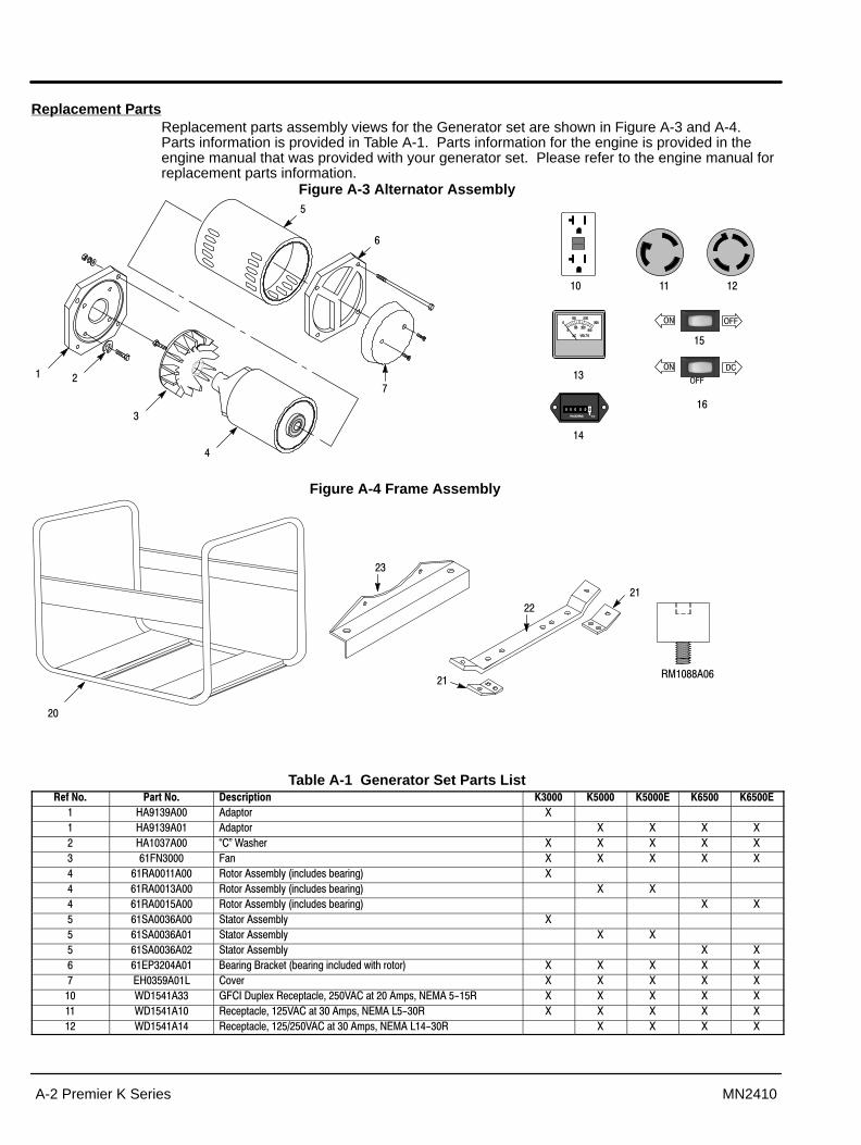
Replacement PartsReplacement parts assembly views for the Generator set are shown in Figure A-3 and A-4. Parts information is provided in Table A-1. Parts information for the engine is provided in theengine manual that was provided with your generator set. Please refer to the engine manual forreplacement parts information.
Figure A-3 Alternator Assembly
�
�
�
-
+
."".5
2�.5
.""
�
�
�
�
-
Figure A-4 Frame Assembly
�
�
�A�** �-
Table A-1 Generator Set Parts List������6 ������6 *�'����� (���� (���� (����� (%��� (%����
/ 0�0 �� ����� 1 / 0�0 � ����� 1 1 1 1 / ��+ �� D�E�!����� 1 1 1 1 1� -"5���� "�8 1 1 1 1 1� -� �� �� ������ ����;$<���8�$# ���;����8�� 1� -� ��� �� ������ ����;$<���8�$# ���;����8�� 1 1� -� ��� �� ������ ����;$<���8�$# ���;����8�� 1 1� -� ���- �� ������� ����;$< 1� -� ���- � ������� ����;$< 1 1� -� ���- � ������� ����;$< 1 1- -,4��� � 6����8��6��������;����8���8�$# � ������������ 1 1 1 1 1+ ,/���0 �� ��:�� 1 1 1 1 1� !2�� �� '"�(�2#�$�>���������$�C���� ������� ���C�5,A ��&�� 1 1 1 1 1 !2�� � ��������$�C��� �������� ���C�5,A ���&��� 1 1 1 1 1 !2�� � ��������$�C������ �������� ���C�5,A ���&��� 1 1 1 1

Premier K Series A-3MN2410
Table A-1 Generator Set Parts List Continued������6 ������6 *�'����� (���� (���� (����� (%��� (%����
5�������8 ,/���� ���6 ��8���$�6�>��.��������4�8�$� 1 1 1 1 15�������8 ,/���� ���6 ��8���$�4�8�$���:����.��������4�8�$� 1 1 1 1 1
� !2�� � ����$��������2#�$����$�� 1 1 1 1 1� !2�� �� /�#��A���� 1 1 1 1 1� �400 ( $���������C���������8������� 1- �40* ( $���������C����������8������� 1 1 1 1
5�������8 �����- �� ( $������8�9����� 1 1 1 15�������8 ,6� �� ( $���A� #$� 1 1 1 15�������8 2(�+- � 2�� � 1 1 1 1 15�������8 ����� �� �������� 1 1 1 15�������8 .����" ���������C��A"2����+�� 15�������8 .�-���" ���������C���A"2����+��C�0�� ����� 1 1 1 15�������8 �%��++ � ����#���6�������� �� 1 1 1 1 15�������8 �%��++ � ����#���6��������� �� 15�������8 �%��++ �� ����#���6�������- �� 1 1 1 1 15�������8 �%��+* �� ����#���6����������� �������8����� �#;$����$�� 1 1 1 15�������8 �40�+0 ����#���6�������������C��242� 1 1 1 1 15�������8 � ���� � "#�$���8� 15�������8 � ��� � "#�$����������'�#�� 15�������8 � ���� �� "#�$���8� 1 1 1 15�������8 � ��� �� "#�$����������'�#�� 1 1 1 15�������8 , �� �� "#�$�"�$���C��8&$�8� 1 1 1 1 15�������8 , ����� ����6 A#99$�� 15�������8 , ����� ���6 A#99$�� 1 1 1 15�������8 , ����� � ������ ������� 1 1 1 1 1
� 6 �*+ ��6 6����"���� 1� 6 �� ��6 6����"���� 1 1 1 1 /6+�� �� ,8��8��A�#8��8��"��� 1 1 1 1 /6+�� �+ ,8��8���8 �9��������������;�� 1 1 1 1� /6-�� �� $���8������8 �9��������������;�� 1
5�������8 �A�** �� (��$����C�,8��8���8 ��8 ���8��������8 ���������8 � 15�������8 �A�** �- (��$����C�,8��8���8 1 1 1 15�������8 �A�** �- (��$����C�'�8��������8 1 15�������8 �A�** �+ (��$����C�'�8��������8 1 15�������8 /6-- �� 6�����<�����2��8 1 15�������8 / �*+ 6�����<�����2��8�6�$� 1 15�������8 /6-�� � 6�����<����� 1 15�������8 , ��� � 6�����<��������C��C�- A4 1 15�������8 �6��0� 2���$C�!��8�8� 15�������8 �6��0� �� 2���$C�!��8�8� 15�������8 �60-�� �� 2���$C�%���� 15�������8 �60-�� � 2���$C�%����C�%����C�%-��� 1 1 1 15�������8 �60-�� �� 2���$C�6�$ �������C��� � 1 1 1 1 15�������8 �60-�- � 2���$C�6�$ �������C��E 1 1 1 1 15�������8 �60-�+ �� 2���$C�%���� 15�������8 �60-�+ � 2���$C�%���� 15�������8 �60-�+ � 2���$C�%����, 15�������8 �60-�+ �� 2���$C�%-��� 15�������8 �60-�+ �� 2���$C�%-���, 1
Wiring Diagrams Wiring diagrams for these generators are contained on the following pages of this appendix.

A-4 Premier K Series MN2410
Figure A-5 K3000 Wiring Diagram

Premier K Series A-5MN2410
Figure A-6 K5000 Wiring Diagram

A-6 Premier K Series MN2410
Figure A-7 K5000E Wiring Diagram

Premier K Series A-7MN2410
Figure A-8 K6500 Wiring Diagram

A-8 Premier K Series MN2410
Figure A-9 K6500E Wiring Diagram

Appendix BPremier R Series
Premier R Series B-1MN2410
Information in this Appendix applies to the following Baldor Generators: R30, R45, R45E, R60, R60E
Caution: The brass connecting tab on some 120VAC duplex receptacles have been removed. Eachreceptacle is powered by a separate generator winding. When replacing a receptacle, inspectthe brass tab that normally links both receptacles. If it is removed, be sure to remove thebrass tab from the replacement receptacle before it is installed. Failure to remove the tab willcause a direct short to the generator windings and cause possible generator damage.
Operator Panel ConfigurationFigure B-1 R30 Operator Panel
� ��!)�-$
�+-)��*���
�� � �� +�-�/���(��
."".5
�����������05 �������������)���������#8 �9�#$������#����8����#����� #�$�>���������$��������� ������ �C��� ���)
$�������*3���:�����������6����8 �� ���#����$ ���������$������ �9����� �C��� ���)
!��8�#��8���������������$�C����#8 �9�#$�����������8�������:� � �;<�����'"�(���������
1�3�����6�2���$�<����������$��#8��������#����9�������8����������)
�3��������$7��96.5�&� #���� $����������:�C��8��8���4A���$$��� #������8�$�� ��������:� ).""�&�,8��8���#8�����9�>� ����� ������;<���:��8���)
�3��/��8�6�4��:� ���:��$�� ����������8�9���������8����������)����$�*�-���
� ��!)�-$
�+$1�-)���$�-
Figure B-2 R45/R45E/R60/R60E Operator Panel �3��������$7��96.5�&� #���� $����������:�C��8��8���4A���$$��� #������8�$�� ��������:� ).""�&�,8��8���#8�����9�>� ����� ������;<���:��8���)
����'���-��6�2���$�<����������$��#8��������#����9�������8����������)
� �!�������6������:�$������� ���$�<������:�$�����$�:�$�;��8����� #�� �;<�������8����������)
� � �3��/��8�'6�4��:� ���:��$�� ����������8�9���������8����������)
� ��!���'��5,A ��&���'"�(����������$�)���������#8 �9�#$������#����8����#����� #�$�>���������$��������� ������ �C��� ���)
� ��!���'��5,A ���&������������$�)������&$������<$����������$������ �9����� �C���� ���)
� �# "��!���'��5,A ���&������������$�)������&$������<$����������$������ �9�������� �C���� ���)
� !)�-��-��
�+-)��*���
2�.5
�� � �� +�-/���(��$
� ��!)�-$
� ��!)�-$
� �# "��!)�-$
� ��!)�-$
����$�*-���

B-2 Premier R Series MN2410
Replacement PartsReplacement parts assembly views for the Generator set are shown in Figure B-3 and B-4. Parts information is provided in Table B-1. Parts information for the engine is provided in theengine manual that was provided with your generator set. Please refer to the engine manual forreplacement parts information.
Figure B-3 Alternator Assembly
�
�
�
-
+
."".5
�
�
�
�
Figure B-4 Frame Assembly
�
�
Table B-1 Generator Set Parts List������6 ������6 *�'����� ��� ��� ���, �-� �-�,
5�������8 ,/��� �� ��8���$�6�>��.��������4�8�$� 15�������8 ,/��� �� ��8���$�4�8�$���:����.��������4�8�$� 15�������8 ,/��+ �� ��8���$�6�>��.��������4�8�$� 1 1 1 15�������8 ,/��� �� ��8���$�4�8�$���:����.��������4�8�$� 1 1 1 1
/ 0�0 �� ����� 1 / 0�0 � ����� 1 1 1 1 / ��+ �� D�E�!����� 1 1 1 1 1� -"5���� "�8 1 1 1 1 1� -� �� �� ������ ����;$<���8�$# ���;����8�� 1� -� ��� �� ������ ����;$<���8�$# ���;����8�� 1 1� -� ��� �� ������ ����;$<���8�$# ���;����8�� 1 1� -� ��0 �� ������� ����;$<��; 1� -� ��� �� ������� ����;$<��; 1 1� -� �� �� ������� ����;$<��; 1 1- -,4��� �- 6����8��6��������;����8���8�$# � ������������ 1- -,4��� � 6����8��6��������;����8���8�$# � ������������ 1 1 1 1

Premier R Series B-3MN2410
Table B-1 Generator Set Parts List Continued������6 ������6 *�'����� ��� ��� ���, �-� �-�,
5�������8 6'-��/�� 6����8����8�$# � ������������ 1 1 1 1 1+ ,/�� �� ��:�� 1 1 1 1 1� !2�� * 2#�$�>���������$�C���� ������� ���C���.� 1� !2�� �� '"�(�2#�$�>���������$�C��� ������� ���C�5,A ��&�� 1 1 1 1 1 !2�� � ��������$�C��� �������� ���C�5,A ���&��� 1 1 1 1 !2�� � ��������$�C������ �������� ���C�5,A ���&��� 1 1 1 1� !2�� � ����$��������2#�$����$�� 1 1 1 1� !2�� �� /�#��A���� 1 1 1 1 1� �40�*� ( $���������C���������8������� 1 1 1 1 1
5�������8 �����- �� ( $������8�9����� 1 1 1 1 15�������8 ,6�� �� ( $���A� #$� 1 1 1 1 15�������8 2(�+- � 2�� � 1 1 1 1 15�������8 ����� �� �������� 1 1 1 15�������8 .�-���" ���������C���A"2����+��C�0�� ����� 1 1 1 15�������8 .����" ���������C��A"2����+�� 15�������8 �%��+� � ����#���6�������� �� 1 15�������8 �%��+� �� ����#���6��������� �� 15�������8 �%��+� �� ����#���6��������� �� 1 15�������8 �%��+� �� ����#���6��������� �� 1 15�������8 �%��+� �- ����#���6�������� �� 1 1
� 6 �*+ ���6 6����"���� 1� 6 ��+ ���6 6����"���� 1 1� 6 ��* ���6 6����"���� 1 1 /6+�� �� ,8��8��A�#8��8��"��� 1 1 1 1 /6+�� �*� ,8��8���8 �9��������������;�� 1 1 1 1� /6-�� ���6 $���8������8 �9��������������;�� 1� /6-�� � $���8������8 �9��������������;�� 1 1 1 1
5�������8 /6-- �� 6�����<�����2��8 1 15�������8 / �*+ 6�����<�����2��8�6�$� 1 15�������8 /6-�� � 6�����<����� 1 15�������8 �6��0� � 2���$C�,8��8������� 1 1 1 1 15�������8 �6��0� �� 2���$C�����F��-� 1 1 1 15�������8 �6��0� �� 2���$C�!��8�8� 1 1 1 1 15�������8 �6��0� �� 2���$C���� 15�������8 �60-�- �� 2���$C�6�$ �������C��)-�E 15�������8 �60-� �� 2���$C���� 15�������8 �60-� �� 2���$C���� 15�������8 �60-�* �� 2���$C����, 15�������8 �60-+ �� 2���$C��-� 15�������8 �60-0 �� 2���$C��-�, 1
�; For generators made before 6/95, consult factory.
Wiring Diagrams Wiring diagrams for each of these generators are contained on the following pages of thisappendix.

B-4 Premier R Series MN2410
Figure B-5 R30 Wiring Diagram

Premier R Series B-5MN2410
Figure B-6 R45/45E Wiring Diagram

B-6 Premier R Series MN2410
Figure B-7 R60 Wiring Diagram

Premier R Series B-7MN2410
Figure B-8 R60E Wiring Diagram
NO
TE
: U
NL
ES
S S
PE
CIF
IED
OT
HE
RW
ISE
1150
1160
5540
5150
5120
5110
1430
1430
5110
5100
1120
1420
5510
1130
5520
8 AWG
IDL
ER
BO
AR
D
2920
BL
UE
TO
FR
AM
EG
ND
5500
GND
AL
L W
IRE
S 1
4 A
WG
.
1110
1160
1110
1410
1120
AM
P
CB
1L
OW
AM
P
1170
VO
LTM
ET
ER
AC
CB
2H
IGH
BL
UE
BL
UE
BLACK
GREEN
GREEN
WHITE
2710
1170
5130
5140
1180
6000
2 T
UR
NS
EA
CH
7000
T1
1600
1500
GN
D
CAPACITOR
1300
1100
1250
1150
1200
1600
1400
1500
1100
SO
LE
NO
IDID
LE
R
5130
5540
5530
5120
1140
1260
1310
1130
5100
1210
1140
5520
5530
2910
1310
1260
1210
2710
1410
5510
5140
1180
EL
AP
SE
D T
IME
ME
TE
R
7000
IDL
ER
SW
ITC
H
2920
2910
6000
TO
FLY
WH
EE
L
1200
1250
1400
2700
1300
2700
J1/P
1
2900
5500
7010
2900
GR
EE
N/Y
EL
ALT
ER
NA
TO
R
6010
GR
EE
N/Y
EL
Ele
ctri
c S
tart
8023
8022
8023
8021
8020
8022
GN
D
GX
(SIL
VE
R)
(GO
LD
)
125/
250V
L14
30R
NE
MA
30A
W
Y
(GO
LD
)
42
11
65
23
L53
0R
NE
MA
125
V
30
A
W(S
ILV
ER
)X
(GO
LD
)
G
2 15 4 37 69 8
125V
20
AN
EM
A
520R
TE
ST
RE
SE
T
125V
20
AN
EM
A
520R
TE
ST
RE
SE
T
HOT
WHITE
HOT
WHITE
LIN
E
LO
AD
WHITE
HOT WHITE
LIN
E
HOT
LO
AD
STA
RT
ER
SO
LE
NO
ID
STA
RT
ER
TO
TO
MA
GN
ET
O
BL
IG
ST
M+
M–

B-8 Premier R Series MN2410

Appendix CPremier OHV Series
Premier OHV Series C-1MN2410
Information in this Appendix applies to the following Baldor Generators: OHV30, OHV50, OHV60, OHV60E, OHV85E
Caution: The brass connecting tab on some 120VAC duplex receptacles have been removed. Eachreceptacle is powered by a separate generator winding. When replacing a receptacle, inspectthe brass tab that normally links both receptacles. If it is removed, be sure to remove thebrass tab from the replacement receptacle before it is installed. Failure to remove the tab willcause a direct short to the generator windings and cause possible generator damage.
Operator Panel ConfigurationFigure C-1 OHV30 Operator Panel
� ��!)�-$
�� � �� +�-�/���(��
������� ���05 �������������)���������#8 �9�#$������#����8����#����� #�$�>���������$��������� ������ �C��� ���)
$�������*3���:�����������6����8 �� ���#����$ ���������$������ �9����� �C���� ��!��8�#��8���������������$�C����#8 �9�#$�����������8�������:� � �;<�����'"�(���������$�)
1�3�����6�2���$�<����������$��#8��������#����9�������8����������)
�3��/��8�6�4��:� ���:��$�� ����������8�9���������8����������)
����$�*-���
� ��!)�-$
Figure C-2 OHV40/OHV50/OHV60/OHV60E Operator Panel �3��/��8�6�4��:� ���:��$�� ����������8�9���������8����������)
� ��!���'��5,A ��&���'"�(����������$�)���������#8 �9�#$������#����8����#����� #�$�>���������$��������� ������ �C��� ���)
� ��!���'��5,A ���&������������$�)������&$������<$����������$������ �9����� �C���� ���)
� �# "��!���'��5,A ���&������������$�)������&$������<$����������$������ �9�������� �C���� ���)
� !)�-��-��
�+-)��*���."".5
� �� +�-/���(��
������$� ��!)�-$
�����$� ��!)�-$
����$�*-���
� �� +�-/���(��
������$� �!)�-$
�����$� �# "�!)�-$
� �!�������6������:�$������� ���$�<������:�$�����$�:�$�;��8����� #�� �;<�������8����������)����'���-��6�2���$�<����������$��#8��������#����9�������8����������)�3��������$7��96�.5�&� #���� $����������:�C��8��8���4A���$$��� #������8�$�� ��������:� )��.""�&�,8��8���#8�����9�>� ����� ������;<���:��8���)
Figure C-3 OHV85E Operator Panel �3��������$7��96.5�&� #���� $����������:�C��8��8���4A���$$��� #������8�$�� ��������:� ).""�&�,8��8���#8�����9�>� ����� ������;<���:��8���)2��.5�&� #���( $������.99��8 �2���#��#�������8�$����:��������9�����$�� �)
����'���-��6�2���$�<����������$��#8��������#����9�������8����������)
� �!�������6������:�$������� ���$�<������:�$�����$�:�$�;��8����� #�� �;<�������8����������)
� � �3��/��8�'6�4��:� ���:��$�� ����������8�9���������8����������)
� ��!���'��5,A ��&���'"�(����������$�)���������#8 �9�#$������#����8����#����� #�$�>���������$��������� ������ �C��� ���)
� ��!���'��5,A ���&������������$�)������&$������<$����������$������ �9����� �C���� ���)
� �# "��!���'��5,A ���&������������$�)������&$������<$����������$������ �9�������� �C���� ���)
� !)�-��-��
�+-)��*���
2�.5
�� � �� +�-/���(��$
� ��!)�-$
� ��!)�-$
� �# "��!)�-$
� ��!)�-$
����$�*-���

C-2 Premier OHV Series MN2410
Replacement PartsReplacement parts assembly views for the Generator set are shown in Figure C-4 and C-5. Parts information is provided in Table C-1. Parts information for the engine is provided in theengine manual that was provided with your generator set. Please refer to the engine manual forreplacement parts information.
Figure C-4 Alternator Assembly
�
�
�
-
+
."".5
�
�
�
�
Figure C-5 Frame Assembly
�
�
/6-�� �
/6-�� ��.�
/6+�� �+.�
/6+�� �*
�A�** �-
Table C-1 Generator Set Parts List������6 ������6 *�'����� )1!�� )1!"�#��#
%�#%��)1!<��
/ 0�0 �� ����� 1 / 0�0 � ����� 1 1 / ��+ �� D�E�!����� 1 1 1� -"5���� "�8 1 1 1� -� �� �� ������ ����;$<���8�$# ���;����8�� 1� -� ��� �� ������ ����;$<���8�$# ���;����8�����./������� 1� -� ��� �� ������ ����;$<���8�$# ���;����8�����./�-��-�,� 1� -� ��- �� ������ ����;$<���8�$# ���;����8�������./�*�,� 1
5�������8 6'-��/�� 6����8����8�$# � ������������ 1 1 1� -� ��0 � ������� ����;$< 1� -� ��� � ������� ����;$<���./������� 1� -� ��� �� ������� ����;$<���./�-�� 1� -� �� � ������� ����;$< 1- -,4��� � 6����8��6��������;����8���8�$# � ������������ 1 1 1+ ,/�� �� ��:�� 1 1+ ,/�� �� ��:�� 1� !2�� �� '"�(�2#�$�>���������$�C���� ������� ���C�5,A ��&�� 1 1 1
5�������8 !2�� * 2#�$�>���������$�C���� ������� ���C���.� 1 !2�� � ��������$�C��� �������� ���C�5,A ���&��� 1 1

Premier OHV Series C-3MN2410
Table C-1 Generator Set Parts List Continued������6 ������6 *�'����� )1!�� )1!"�#��#
%�#%��)1!<��
!2�� � ��������$�C������ �������� ���C�5,A ���&��� 1 1 !2�� � ��������$�C������ ������� ���C�5,A ���&����#8����;�9����*�00� 1� !2�� � ����$��������2#�$����$�� 1 1� !2�� �� /�#��A���� 1 1 1
5�������8 ,/��� �� ��8���$�4�8�$�6�>C�,���<��.��������4�8�$� 15�������8 ,/���� �� ��8���$�4�8�$�6�>C�,���<��.��������4�8�$� 15�������8 ,/��+ �� ��8���$�4�8�$�6�>C�,���<��.��������4�8�$� 15�������8 ,/��� �� ��8���$�4�8�$���:����.��������4�8�$� 15�������8 ,/���� �� ��8���$�4�8�$���:����.��������4�8�$� 15�������8 ,/���* �� ��8���$�4�8�$���:����.��������4�8�$� 1
� �40�*� ( $���������C���������8������� 1 15�������8 /6-�- �� ( $���������$����:�� 15�������8 /6-�* ��G ( $���������$����:�� 15�������8 ,6� �� ( $���A� #$� 1 15�������8 �����- �� ( $������8�9����� 1 15�������8 , ��� �� ( $���A��8�� 1 15�������8 2(�+- � 2�� � 1 1 15�������8 ����� �� �������� 1 15�������8 .����" ���������C�.(���A"2����+�� 15�������8 .�-���" ���������C�.(����A"2����+��C�0� �� 1 15�������8 �%��+� � ����#���6������C�� 15�������8 �%��+� � ����#���6������C�� 15�������8 �%��+� �� ����#���6������C��� 1 15�������8 �%��+� �� ����#���6������C��� 1 15�������8 �%��+� �� ����#���6������C��� 15�������8 �%��+� �- ����#���6������C�� 15�������8 � ���� � "#�$���8� 15�������8 � ���� � "#�$���8� 15�������8 � ���� �� "#�$���8� 15�������8 � ��� � "#�$����������'�#�� 1 15�������8 � ��� �� "#�$����������'�#�� 15�������8 , �� �� "#�$�"�$���C��8&$�8� 1 1 1
� 6 �*+ ��6 6����"���� 1� 6 �*+ ��6 6����"���� 1� 6 �** ���6 6����"���� 1 /6+�� �� ,8��8��A�#8��8��"��� 1 /6+�� ��G ,8��8��A�#8��8��"��� 1 /6+�� �+ ,8��8���8 �9��������������;�� 1 /6+�� �*� ,8��8���8 �9��������������;�� 1� /6-�� ���6 $���8������8 �9��������������;�� 1� /6-�� � $���8������8 �9��������������;�� 1 1
5�������8 �A�** �- ��;�����8�(��$����C�'�8��������8 1 15�������8 �A�** �+ ��;�����8�(��$����C�,8��8���8 1 15�������8 �60-�- �� 2���$C�6�$ �������C��)-�E 1 1 15�������8 �60-�- � 2���$C�6�$ �������C�-)��E 1 15�������8 �60-�- �� 2���$C�6�$ �������C�+)��E 15�������8 �60-- �� 2���$C�./��� 15�������8 �60-- �� 2���$C�./�-� 15�������8 �60- �� 2���$C�./�-�, 15�������8 �60-* �� 2���$C�./�*�,���� �� 15�������8 �6��0� �� 2���$C���8 #���6�>C�.5&."" 15�������8 �6��0� �� 2���$C�./��&- 15�������8 �6��0� �+ 2���$C��������A ������8$<� 15�������8 �6��0� 2���$C�!��8�8� 15�������8 �6��0� �� 2���$C�!��8�8� 1 15�������8 �6��0� �� 2���$C�./�*�,����8�$� 1
Wiring Diagrams Wiring diagrams for these generators are contained on the following pages of this appendix.

C-4 Premier OHV Series MN2410
Figure C-6 OHV30 Wiring Diagram

Premier OHV Series C-5MN2410
Figure C-7 OHV40 / OHV50 / OHV60 Wiring Diagram

C-6 Premier OHV Series MN2410
Figure C-8 OHV60E Wiring Diagram

Premier OHV Series C-7MN2410
Figure C-9 OHV 85E Wiring Diagram

C-8 Premier OHV Series MN2410

Appendix DPremier OHV100E Series
Premier OHV100E Series D-1MN2410
Information in this Appendix applies to the OHV100E Baldor Generator.
Caution: The brass connecting tab on some 120VAC duplex receptacles have been removed. Eachreceptacle is powered by a separate generator winding. When replacing a receptacle, inspectthe brass tab that normally links both receptacles. If it is removed, be sure to remove thebrass tab from the replacement receptacle before it is installed. Failure to remove the tab willcause a direct short to the generator windings and cause possible generator damage.
Operator Panel ConfigurationFigure D-1 OHV100E Operator Panel
�3��������$7��96.5�&� #���� $����������:�C��8��8���4A���$$��� #������8�$�� ��������:� ).""�&�,8��8���#8�����9�>� ����� ������;<���:��8���)
����'���-��6�2���$�<����������$��#8��������#����9�������8����������)
� �!�������6������:�$������� ���$�<������:�$�����$�:�$�;��8����� #�� �;<�������8����������)
� � �3��/��8�'6�4��:� ���:��$�� ����������8�9���������8����������)
� ��!���'��5,A ��&���'"�(����������$�)���������#8 �9�#$������#����8����#����� #�$�>���������$��������� ������ �C��� ���)
������$�� ��!���'��5,A ���&������������$�)������&$������<$����������$������ �9����� �C���� ���)
������$�� �# "��!���'��5,A ���&������������$�)������&$������<$����������$������ �9�������� �C���� ���)
������$�� �# "��!���'����-�-0���������$�)������&$������<$����������$������ �9�������� �C���� ���)
� !)�-��-��
�+-)��*���
."".5
�� � �� +�-/���(��$
� ��!)�-$
������$� ��!)�-$
������$� �# "��!)�-$
����$�*-���
����������
� ��!)�-$
������"����
������$� �# "��!)�-$

D-2 Premier OHV100E Series MN2410
Replacement PartsReplacement parts assembly views for the Generator set are shown in Figure D-2 and D-3. Parts information is provided in Table D-1. Parts information for the engine is provided in theengine manual that was provided with your generator set. Please refer to the engine manual forreplacement parts information.
Figure D-2 Alternator Assembly
�
�
�
-
+."".5
�
�
�-
�
Figure D-3 Frame Assembly
�
�

Premier OHV100E Series D-3MN2410
Table D-1 Generator Set Parts List������6 ������6 *�'�����
/6-++ � ����� / �** �� 6�$�C������� ������8�
5�������8 /6-�� �� .&��8�C�6����8��4�������8��8 ����$� -"5��� "�8� -� ��� �� ������ ����;$<���8�$# ���;����8��
5�������8 6'-�+/�� 6����8����8�$# � ������������� -� ���- �� ������� ����;$<- -,4�� � 6����8��6��������;����8���8�$# � ������������
5�������8 -,1��� � ,>������"��$ � ����;$<5�������8 /����0 �� /������8��C������9���5�������8 2(�++ �� �����9���C��������8�$�;�� ��
+ ,/��� �� ��:��� !2�� �� '"�(�2#�$�>���������$�C���� ������� ���C�5,A ��&�� !2�� � ��������$�C��� �������� ���C�5,A ���&��� !2�� � ��������$�C������ �������� ���C�5,A ���&���� !2�� � ����$��������2#�$����$��� !2�� �� /�#��A����� !2�� * ��������$�C������ �������� ���C���-�-0
5�������8 ,/��+ �� �� ����8���$�4�8�$�6�>5�������8 ,/���� �� ��:��C��� ����8���$�4�8�$�6�>5�������8 ,/��� �� ,8 ���8���$�4�8�$�6�>5�������8 ,/��� �� ��:��C�,8 ���8���$�4�8�$�6�>C�$�#:��� �9��8�
- �40�*� ( $���������C���������8�������5�������8 /6-�+ �� ( $���������$����:��5�������8 ,6� �� ( $���A� #$�5�������8 �����- �� ( $������8�9�����5�������8 , ��� �� ( $���A��8��5�������8 �%��+� �� ����#���6������C��� 5�������8 ,A��+ �� ��$��������#$����5�������8 "H��-- �� "#��C���$��������#$����5�������8 "H��-� �� "#���/�$ ��C���$��������#$����5�������8 � ���� � "#�$���8�5�������8 � ��� � "#�$����������'�#��5�������8 , �� �� "#�$�"�$���C��8&$�8�
� 6 �0+ ���6 6����"���� /6+�� ��G ,8��8��A�#8��8��"��� /6+�� �*� ,8��8���8 �9��������������;��� /6-�-* �� $���8������8 �9��������������;��
5�������8 /6+�� �� ��;�����8�(��$����C�����������;���5�������8 �A�** �+ ��;�����8�(��$�����A�#8�5�������8 �60-�- �� 2���$C�6�$ �������C��)-�E5�������8 �60-�- � 2���$C�6�$ �������C�-)��E5�������8 �60-�- �� 2���$C�6�$ �������C�+)��E5�������8 �6��0� �� 2���$C���8 #���6�>C�.5&.""5�������8 �6��0� 2���$C�!��8�8�5�������8 �6��0� � 2���$C�./���,C�4�8�$5�������8 �6��0� �� 2���$C�!��8�8�5�������8 �60- �� 2���$C�./���,C��� �5�������8 /6-- �� 6�����<�����2��85�������8 / �*+ 6�����<�����2��8�6�$�5�������8 /6-�� � 6�����<�����
Wiring Diagrams Wiring diagrams for the OHV100E generator are contained on the following pages of thisappendix.
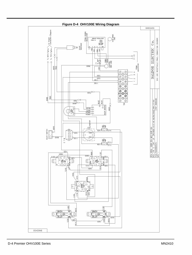
D-4 Premier OHV100E Series MN2410
Figure D-4 OHV100E Wiring Diagram

Premier OHV100E Series D-5MN2410
Figure D-5 OHV100E Generator Output Wiring Diagram

D-6 Premier OHV100E Series MN2410
Figure D-6 OHV100E DC Wiring Diagram

Appendix EPremier OHV110E Series
Premier OHV110E Series E-1MN2410
Information in this Appendix applies to the OHV110E Baldor Generator.
Caution: The brass connecting tab on some 120VAC duplex receptacles have been removed. Eachreceptacle is powered by a separate generator winding. When replacing a receptacle, inspectthe brass tab that normally links both receptacles. If it is removed, be sure to remove thebrass tab from the replacement receptacle before it is installed. Failure to remove the tab willcause a direct short to the generator windings and cause possible generator damage.
Operator Panel ConfigurationFigure E-1 OHV110E Operator Panel
�3��������$7��96.5�&� #���� $����������:�C��8��8���4A���$$��� #������8�$�� ��������:� ).""�&�,8��8���#8�����9�>� ����� ������;<���:��8���)
����'���-��6�2���$�<����������$��#8��������#����9�������8����������)
� �!�������6������:�$������� ���$�<������:�$�����$�:�$�;��8����� #�� �;<�������8����������)
� � �3��/��8�'6�4��:� ���:��$�� ����������8�9���������8����������)
� ��!���'��5,A ��&���'"�(����������$�)���������#8 �9�#$������#����8����#����� #�$�>���������$��������� ������ �C��� ���)
������$�� ��!���'��5,A ���&������������$�)������&$������<$����������$������ �9����� �C���� ���)
������$�� �# "��!���'��5,A ���&������������$�)������&$������<$����������$������ �9�������� �C���� ���)
������$�� �# "��!���'����-�-0���������$�)������&$������<$����������$������ �9�������� �C���� ���)
� !)�-��-��
�+-)��*���
."".5
�� � �� +�-/���(��$
� ��!)�-$
������$� ��!)�-$
������$� �# "��!)�-$
����$�*-���
����������
� ��!)�-$
������"����
������$� �# "��!)�-$

E-2 Premier OHV110E Series MN2410
Replacement PartsReplacement parts assembly views for the Generator set are shown in Figure E-2 and E-3. Parts information is provided in Table E-1. Parts information for the engine is provided in theengine manual that was provided with your generator set. Please refer to the engine manual forreplacement parts information.
Figure E-2 Alternator Assembly
�
�
�
-
+."".5
�
�
�-
�
Figure E-3 Frame Assembly
�
�

Premier OHV110E Series E-3MN2410
Table E-1 Generator Set Parts List������6 ������6 *�'�����
/6-++ � ����� / �** �� 6�$�C������� ������8�
5�������8 /6-�� �� .&��8�C�6����8��4�������8��8 ����$� -"5��� "�8� -� ��� �� ������ ����;$<���8�$# ���;����8��
5�������8 6'-�+/�� 6����8����8�$# � ������������� -� ���- �� ������� ����;$<- -,4�� � 6����8��6��������;����8���8�$# � ������������
5�������8 -,1��� � ,>������"��$ � ����;$<5�������8 /����0 �� /������8��C������9���5�������8 2(�++ �� �����9���C��������8�$�;�� ��
+ ,/��� �� ��:��� !2�� �� '"�(�2#�$�>���������$�C���� ������� ���C�5,A ��&�� !2�� � ��������$�C��� �������� ���C�5,A ���&��� !2�� � ��������$�C������ �������� ���C�5,A ���&���� !2�� � ����$��������2#�$����$��� !2�� �� /�#��A����� !2�� * ��������$�C������ �������� ���C���-�-0
5�������8 ,/��+ �� �� ����8���$�4�8�$�6�>5�������8 ,/���� �� ��:��C��� ����8���$�4�8�$�6�>5�������8 ,/��� �� ,8 ���8���$�4�8�$�6�>5�������8 ,/��� �� ��:��C�,8 ���8���$�4�8�$�6�>C�$�#:��� �9��8�
- �40�*� ( $���������C���������8�������5�������8 ,6�- � ( $���A� #$�5�������8 �����- �� ( $������8�9�����5�������8 , ���� � ( $�������8�5�������8 �,���0 �� ( $�����$�8�� 5�������8 �%��+� �� ����#���6������C��� 5�������8 ,A��+ �� ��$��������#$����5�������8 "H��-- �� "#��C���$��������#$����5�������8 "H��-� �� "#���/�$ ��C���$��������#$����5�������8 � ���� � "#�$���8�5�������8 � ��� � "#�$����������'�#��5�������8 , �� �� "#�$�"�$���C��8&$�8�
� 6 �� ���6 6����"���� /6+�� ��G ,8��8��A�#8��8��"��� /6-�� �� ,8��8���8 �9��������������;��� /6-�-* �� $���8������8 �9��������������;��
5�������8 /6+�� �� ��;�����8�(��$����C�����������;���5�������8 �A�** �+ ��;�����8�(��$�����A�#8�5�������8 �60-�- �� 2���$C�6�$ �������C��)-�E5�������8 �60-�- � 2���$C�6�$ �������C�-)��E5�������8 �60-�- �� 2���$C�6�$ �������C�+)��E5�������8 �6��0� �� 2���$C���8 #���6�>C�.5&.""5�������8 �6��0� 2���$C�!��8�8�5�������8 �6��0� � 2���$C�./���,C�4�8�$5�������8 �6��0� �� 2���$C�!��8�8�5�������8 �60-� �� 2���$C�./��,C��� �5�������8 /6-- �� 6�����<�����2��85�������8 / �*+ 6�����<�����2��8�6�$�5�������8 /6-�� � 6�����<�����5�������8 , ���0 +� .�$�4����#���������5�������8 �40� %�<�������C��8��8��������8�5�������8 �,���+ �� ��$�8�� C���,8��8��������8�
Wiring Diagrams Wiring diagrams for the OHV110E generator are contained on the following pages of thisappendix.

E-4 Premier OHV110E Series MN2410
Figure E-4 OHV110E Wiring Diagram
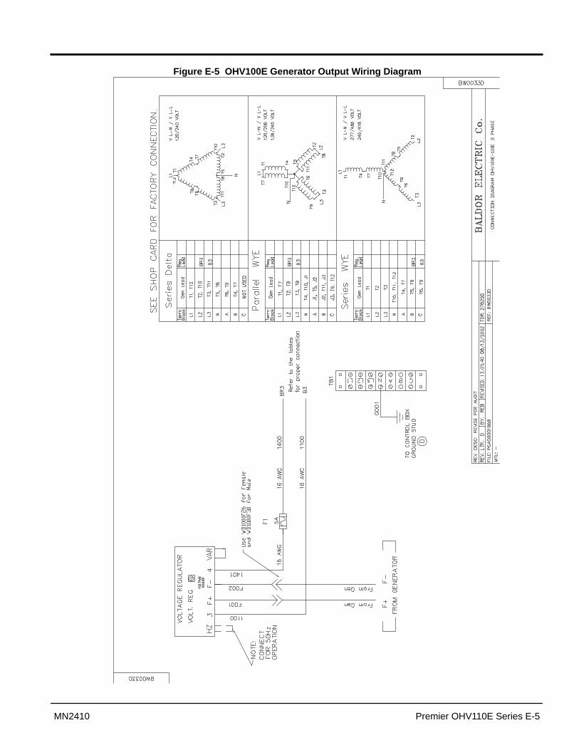
Premier OHV110E Series E-5MN2410
Figure E-5 OHV100E Generator Output Wiring Diagram

E-6 Premier OHV110E Series MN2410
Figure E-6 OHV110E DC Wiring Diagram

Baldor District Offices+��-�*�$-�-�$
�(G.5 4/.,5(1�������2�4� �,4/.,5(1C� G���*����4/.5,I�-�&�+�&���+" 1I�-�&�+�&��-�
� �(".�5( �.�� 5',�,�-�*��"�.�(�� �.AA,��,C�� ����0����4/.5,I���&+�&-++" 1I���&+&�*�0
/ 3! �2��-�".�6,�����,,�/ 3! �2C�� ��0����4/.5,I���&+*�&00��" 1I���&+*�&00�
�.�.� 2.2,5�,����!�6 �6,��3�4� �,2,5�,�C��.���*���4/.5,I����&-�&�+" 1I����&�0�&�++
�.55,��(�H�! ��(5'".�2-���.H�/��H�54(%,��. 2! ��(5'".�2C�����-�04/.5,I���&-0&���" 1I���&-0&��*�
"�.�(2 � A4 �4H,��.��(�.��(�'(5�(�� 52��0�-�, ����/� �,5H,� A4 C�"������-��4/.5,I�*�&�*&��+*" 1I�*�&�+&0*�
',.�'( �� 5� -��,�/5.�.'3�2�)� �4/ �,�� C�' ��������4/.5,I�++�&++&+���" 1I�++�&++&+��
(��(5.(��/(� '.+0��A(��,��2�(�,!..2�2 �,C�(���-�04/.5,I�-��&+*+&0-��" 1I�-��&+*+&����
(52( 5 (52( 5 4.�(�����!)�A(55,�.� ���)(52( 5 4.�(�C�(5���-�4/.5,I��+&�-&���" 1I��+&�-&��*��&�*&��
(.! 2,��A.(5,�0��6,��� �,)C��H(�,�+2,��A.(5,�C�( �������4/.5,I���&��&000-" 1I���&��&-�
A �3� 526 ��(A.�,---��� 5� �6 �6 � ��2�H(�,�&�,�%�(2',C�A2)��+�4/.5,I���&�+0&��" 1I���&�+0&-++
A �� �/H�,���6.��.5�+�6�..%����)!.��,��,�C�A ��-�-4/.5,I���*&*��&�+�*" 1I���*&*��&�0
A(�/(' 52,��.(���+*���,��(5'�4.52��6��2)��,��(5'�/,('/��C�A(��*�4/.5,I��*-&0+*&0*��" 1I��*-&0+*&00-0
'� 52�� 4(2�--*���A(�,��. 2�5!'� 52�� 4(2�C�A(��0���4/.5,I�--&+*�&+*�" 1I�--&+*�&+**
A(55,�.� A(55, 4.�(��*�����/� �,)�5.��/�.',��C�A5������+�4/.5,I�+-�&�*&�-��" 1I�+-�&�*&���
A(��.H�(����.H(���(52H���( ��2�(�,A �3� 52�/,('/��C�A.��-����4/.5,I���&0*&*��" 1I���&0*&+--�
% 5� ���(�30��5�!�4� ��,�� ��,3�2��(�,��(2,C�A.���-���4/.5,I�*-&�*+&�+" 1I�*-&�*+&�+��
5,!�3.�% H6H�5.5,�,��(��2�(�, H6H�5C�53�����4/.5,I���&��&����" 1I���&��&00�
5.��/�� �.�(5 '�,,5�6.�.���.�/,�!..2��. 2'�,,5�6.�.C�5����+��-4�.�6.1�-���'�,,5�6.�.C�5���+�-4/.5,I���-&+&-��" 1I���-&+�&--*
./(.�(5�(55 �(0���, �/ ����.H���H(�,���/,6�.5C�%3�����*4/.5,I�*�0&�*-&�" 1I�*�0&�*-&�++0
��,�,� 52*00�"�,,! 3�2�(�,A �,2.5( C�./�����-4/.5,I����&�-*&�+++" 1I����&�-*&�++*
.%� /.A �� �H��
�, ���2 !,��6(163C�.%�+���*4/.5,I�0*&�--&0��" 1I�0*&�--&0��*
.�,'.54.��� 52��0���!� �,�3��.H���H � �(5C�.��0+�-4/.5,I����&-0&0��" 1I����&-0&0�
4,55�3�� 5( 4/(� 2,�4/( �����/.A ��6H��/�A,A.�( ��/('/! 34,55� H%,5C�5=���*�4/.5,I�*�-&--&��" 1I�*�-&--�&-�-�
4(���6H�'/--/�6, ��3��. 2A.5�.,�(��,C�4 ����-4/.5,I��&�*�&+��" 1I���&�*�&+��
�,55,��,,A,A4/(������!(5�/,��,���. 2A,A4/(�C��5����**4/.5,I�0�&�-�&��" 1I�0�&�-�&�0�
�,1 �/.H��.5�-�+�4(5,��(A6,���H(�,�J���/.H��.5C��1��++��4/.5,I�+�&*0�&+�-" 1I�+�&-0�&����
2 �� ������KH,6,�2 �� �C��1��+��+4/.5,I��&-��&++" 1I��&-��&**+�
.2,�� -0-*�, ����.AA,��,.2,�� C��1��+0+-4/.5,I���&�-+&+�+" 1I���&�-+&0*++
H� /� ���� %,��(�3����.H�/�A (5����,,�� ���� %,��(�3C�H��*��4/.5,I�*�&*�&�+" 1I�*�&*�&*0
!(��.5�(5A(�! H%,,+���.H�/�-��2����,,�5,!�6,��(5C�!(�����4/.5,I�-&+*�&�0��" 1I�-&+*�&�
(5�,�5 �(.5 ��� �,�".����A(�/C� �6 �2.��,�,���(���.".����A(�/C� ���+0�4/.5,I��+0&-�-&�+" 1I��+0&-�*&�*0��
� 5 2 � ,2A.5�.5C� �6,��
����&0����,,�,2A.5�.5C� �6,�� ���-,-�*4/.5,I�+*�&���&�0��" 1I�+*�&��*&-��
. %�(��,C�.5� �(.+����.�,5��3��. 2. %�(��,C�.5� �(.��-/-�4/.5,I�0��&*0&���" 1I�0��&*0&���
A.5��, �C�KH,6,�*���!(��( A����,,�A.5��, �C�KH,6,��/�=��4/.5,I���&0��&+" 1I���&0��&*-�0
� 5�.H�,�C�6�(�(�/��.�HA6( ��*�%,6,��! 34.����.KH(�� AC�6�������A�4/.5,�-��&�&*" 1I�-��&�&��
!(55(4,'C�A 5(�.6 ���4�(5�,������,,�!(55(4,'C�A 5(�.6 ���6%4/.5,I���&0�&���" 1I���&0�-&��
H��� �( H5(���C�-��� 5�.5��. 2�,�,5�/(���C�5�!��+C�� H��� �( 4/.5,I��-�����0-+������" 1I��-�����0-+���0�
H5(��*C���%,��,�����. 2�.!�(��,C��(��.�( C��+*�� H��� �( 4/.5,I������0+�������" 1I������0+�����--
�/(5 �/ 5'/ (�=( /H �6H�(5,����,5�,��..A�5.)��&��*�*�/.5'�K( .��. 2�/ 5'/ (����4/.5,I�*-&&-��+��-�" 1I�*-&&-��+*-�
,��� �� 2.�6 �2.���,5��. A,�(� �,�(2,5�( ��4(5 �,��2,��H(G 4.�)���J��C�5� )�� 5�� �� 2.�,��� �� 2.�C��,5��.� A,�(� 4/.5,I�������**&�0" 1I�������**&�*
"� 5�,C��H,�2H�� ��.5�0�����A �.��,��,5�6�(,4/.5,I���������+0�" 1I�������00��*-�
',�A 532(,�,���� ��,�2&*����%(��//,(A�AH5(�/C�',�A 534/.5,I���0���*0��0���*�&��" 1I���0���*0��0���*�&��0
(� �36�$ ��� ��� 'A�8 ������.99�������6������8�C�� -*���A�8 ���������@��$�8 4/.5,I�����0�-���00���" 1I�����0�-���-���
= 4 55,.�A(A,���&��2 (A �/(C�% 5 ' ! &%H3.%./ A C�&�*��C�= 4 5�4/.5,I�*&��&�&���-" 1I�*&��&�&���+
AL1(�.6��2)� �� ,�.4H,��.C�%A)��,M5��+���C�'H 5 =H �.CAL1(�.4/.5,I��&�++&+-&���" 1I��&�++&+-&��
4 5 A 6 �2.���H2 A,�(� 0�0��**C�G.5 �-�6,�/ 5( 4 5 AN��(�3C��,4)�2,�4 5 AN4/.5,I����+��-&���+" 1I����+��-&����
�(5' 4.�,��% %(�6H%(���. 2�%�6�! �,/.H�,��.A4�,1�(5' 4.�,��+*-�4/.5,I��-���-�+����+" 1I��-���-�+�+�+�*
�!(�G,�� 524.��" �/�+���/H�G,5��� ��,��0�/&*���",H,��/ �,5�!(�G,�� 524/.5,I���������-�+�+��" 1I���������-�0�0�
� (! 5�..A��C�"C�5.)����/H5'��/,5'��. 2C��/(/�(5�2(��)� (4,(��4/.5,I�**-&&*��&---�,1�)�*���" 1I�**-&&*��&++
H5(�,2�%(5'2.A-�6�(��.��2(���(6H�(.5�4 �%/ !%�,3�2�(�,6�(��.��6����6"��H)%)4/.5,I��������*�����" 1I��������*�0���

BALDOR GENERATORS3815 Oregon StreetOshkosh, WI 54902
(920) 236–4200 or (800) 872–7697Fax (920) 236–4219
www.baldor.com
Baldor Electric CompanyMN2410
Printed in USA1/04 C&J1000
WARNING:CALIFORNIA PROPOSITION 65 WARNING:
Engine exhaust from this product contains chemicals knownto the state of California to cause cancer, birth defects andother reproductive harm.
WARNING:CALIFORNIA PROPOSITION 65 WARNING:
Diesel engine exhaust and some constituents are known to thestate of California to cause cancer, birth defects and otherreproductive harm.
WARNING:CALIFORNIA PROPOSITION 65 WARNING:
Battery posts, terminals and related accessories are known tothe state of California to cause cancer, birth defects and otherreproductive harm.