preliminary report of open source requirements and...
TRANSCRIPT

Coordination and Support Action Funded by the European Union’s Seventh Framework Programme for research, technological development and demonstration under grant agreement no. 619712.
Strategic objective: ICT-2013.1.1 Future Networks
Start date of project: November 1, 2013 (24 months duration)
Deliverable D4.1 Preliminary Report of Open Source Requirements and Implementations
Due date: Nov 15, 2014
Submission date: Nov 14, 2014
Deliverable leader: SSSA
Author list: F. Paolucci (SSSA), M. Dallaglio (SSSA), G. Bernini (NXW), R.Casellas (CTTC), R.Muñoz (CTTC), R.Martínez (CTTC), R. Vilalta (CTTC), O. Dugeon (Orange), T. Das (TUBS), X. Masip (UPC), V. Barbosa (UPC), O. Gonzalez de Dios (TID)
Dissemination Level
PU: Public
PP: Restricted to other programme participants (including the Commission Services)
RE: Restricted to a group specified by the consortium (including the Commission Services)
CO: Confidential, only for members of the consortium (including the Commission Services)

Preliminary Report of Open Source Requirements and Implementations
Project: PACE Deliverable Id.: Deliverable D4.1 Submission Date: Nov 14, 2014
2
Preliminary Report of Open Source Requirements and Implementations
Project: PACE Deliverable Id.: Deliverable D4.1 Submission Date: Nov 14, 2014
3
Abstract This deliverable reports the PACE consortium output related to Open Source requirements, tools and
implementations in the first year of the project, under the guidance of Work Package 4 "Open Source
Community".
The deliverable covers the PACE Open Source activities and efforts agreed under the umbrella of PCE
architectures considered within the project. Open Source requirements in terms of reference architectures,
interfaces and models, with particular focus to TED models, are first reported. A preliminary assessment and
description of Open Source interfaces, tools, extensions and experimental platforms are then reported. Open
Source services, extensions and tools are being conceived in order to allow external/third party users to utilize
or test available PCE-based facilities, software and platforms while encouraging joint research activities and
experimental evaluation of PCE-based control plane tools.
Finally, the instruments used by the Coordinated and Support Action consortium to disseminate are also
reported, including Open Source forums and wiki, public repositories, PACE workshops focused on Open
Source.

Preliminary Report of Open Source Requirements and Implementations
Project: PACE Deliverable Id.: Deliverable D4.1 Submission Date: Nov 14, 2014
4

Preliminary Report of Open Source Requirements and Implementations
Project: PACE Deliverable Id.: Deliverable D4.1 Submission Date: Nov 14, 2014
5
Table of Contents
0 Executive Summary 7
1 Open Source Requirements and References 9
1.1 Reference Architectures 9
1.1.1 GMPLS and PCE 9
1.1.2 Multi-domain Path Computation 11
1.1.3 PCE Framing into SDN 12
1.2 PCE Database Models 14
1.2.1 Traffic Engineering Database 14
1.2.2 Assumption and Hypothesis 15
1.2.3 Database Requirements 15
1.2.4 PCE-DB model 17
1.2.5 PCE-DB Population 19
1.3 Performance Metrics 21
1.3.1 Network Operation Parameters 21
1.3.2 Security Parameters 22
1.3.3 IoT Parameters 23
2 PACE Open Source Implementations and Collaborative Platform 25
2.1 Open Source PCE and Control Plane Emulators 25
2.1.1 TUBS PCEe 25
2.1.2 Telefonica Netphony 27
2.1.3 Orange QUAGGA Extensions 32
2.2 Open Source Libraries and Tools 36
2.2.1 Javascript cne-tNetwork graph Visualization Library 36
2.2.2 Open Source PCEP Grammar Tool 43
2.3 PCE as a Service: Open Source Path Computation Evaluation 45
2.4 Open Source PCEP Dissector 46
2.5 Open Source PCE Simulators 47
2.5.1 PCE Extensions in OPNET Simulator 48
2.6 Experimental Collaborative Platform 53
3 PACE Instruments for Open Source Dissemination 57
3.1 Open Source Forum 57
3.2 Open Source Repository 57
3.3 Open Source Workshops 58
Preliminary Report of Open Source Requirements and Implementations
Project: PACE Deliverable Id.: Deliverable D4.1 Submission Date: Nov 14, 2014
6
3.3.1 TID Workshop 58
3.3.2 SSSA Workshop co-located with ONDM 59
4 Conclusions 61
5 References 63
6 Acronyms 67
Figure Summary Figure 2-1 Overview of the Open Source PCE. 26 Figure 2-2 Netphony topology module. 30 Figure 2-3 Netphony PCE architecture and modules. 31 Figure 2-4 Netphony development workflow. 32 Figure 2-5 cne-tNetwork: example 1. 41 Figure 2-6 cne-tNetwork: example 2. 42 Figure 2-7 cne-tNetwork: IDEALIST EON emulator GUI. 42 Figure 2-8 cne-tNetwork: STRAUSS SDN orchestration GUI. 43 Figure 2-9 PCEP Grammar reference interface. 44 Figure 2-10 Example of PCEP PCReq. 45 Figure 2-11 PCE as a service. Internal architecture of PCE. 46 Figure 2-12 Wireshark PCEP dissector: PCReq with P2MP LSP request. 47 Figure 2-13. Wireshark PCEP dissector: PCRep with ERO and SERO. 47 Figure 2-14 OPNET Modeler. 48 Figure 2-15 PCEP Root FSM. 49 Figure 2-16 PCEP Child FSM. 50 Figure 2-17 IPSec Hub connectivity using CTTC gw as hub. 54 Figure 2-18 Example TED topology emulated using the infrastructure. 56
Table Summary Table 1 TE commands. 33 Table 2 OSPF-TE daemon commands. 34 Table 3 OSPF information commands. 34 Table 4 IS-IS daemon commands. 36

Preliminary Report of Open Source Requirements and Implementations
Project: PACE Deliverable Id.: Deliverable D4.1 Submission Date: Nov 14, 2014
7
0 Executive Summary
One of the main targets of the CSA PACE project is to promote the utilization of the Path Computation Element (PCE)
architecture, and, more generally, of control plane solutions and platforms based on PCE technologies. A key instrument
to enable such promotion is represented by the dissemination of Open Source interfaces, tools, extensions and platforms
to external users.
The Open Source activities and their implementation are under the responsibility of PACE work package 4 (WP4) : "Open
Source Community". The activities of WP4 include the organization of a collaborative multi-partner platform for Open
Source tools, the definition of Open Source requirements in terms of reference architectures, common models and
specifications going beyond the definitions given by standardization bodies, reference performance metrics, the
collection of various Open Source tools, extensions, platforms, libraries under the common umbrella of PACE Open
Source software repository for collaborative activities among PACE partners, third party utilization and evaluation,
external collaborations.
This deliverable reports the results of the first year of activity of the PACE Open Source community, led by WP4. The
main topics of the deliverable are hereafter summarized and include the following topics:
Open Source requirements: During the first year, in the context of Task 4.1, PACE partners discussed on the
main common requirements for Open Source software features. In particular, three main aspects have been
discussed and agreed: 1) reference architectures to be considered, supported by PACE, 2) reference models
beyond standard recommendation, with particular focus on PCE key internal modules such as databases (i.e.,
Traffic Engineering Database (TED) reference information model), 3) common performance metrics definition in
order to provide reference evaluation tools. Such requirements are defined, reported and discussed in Chapter
1.
Open Source tools, interfaces, collaborative platform: In the context of Task 4.2 and 4.3, Open Source
instruments made available by the PACE project are described in detail. Most of these software instruments are
the research output of PACE partners under other EU projects (e.g., IDEALIST, STRAUSS). The target of PACE
project is to catalogue them, provide and guarantee reference support (e.g., TED model) and disseminate code
and features for collaborative and third party utilization. The catalogued software includes: 1) PCE emulators, 2)
software extensions for QUAGGA environment, 3) PCE service for Open Source path computation algorithm
evaluation, 4) PCE-based extensions for network simulators, 5) network analyzer PCE Protocol (PCEP) dissectors
extensions, 6) libraries and network visualization tools, 7) description and joining requirements of the

Preliminary Report of Open Source Requirements and Implementations
Project: PACE Deliverable Id.: Deliverable D4.1 Submission Date: Nov 14, 2014
8
collaborative inter-partner control plane testbed, where Open Source tools may be tested, evaluated and
validated.
Open Source dissemination instruments: three ways are utilized by the CSA to disseminate Open Source
activities and tools: 1) the Open Source forum, available within the PACE websites through several segments
(i.e., public mailing list, public wiki), 2) the Open Source Repository, hosting the Open Source codes, 3) the Open
Source-oriented PACE Workshops, that will be held in January 2015 in Madrid, Spain (organized by TID) and in
May 2015 (organized by SSSA, co-located with ONDM 2015 international conference).

Preliminary Report of Open Source Requirements and Implementations
Project: PACE Deliverable Id.: Deliverable D4.1 Submission Date: Nov 14, 2014
9
1 Open Source Requirements and References
In this chapter, the PACE CSA consortium reports the discussion, consideration and agreements on the general
requirements of Open Source tools, interfaces and extensions that the consortium supports and disseminates for
external use and evaluation. First, reference PCE and control plane architectures and standards are described, that will
be considered for the development of Open Source tools. Then, particular effort has been dedicated to the discussion
and the definition of reference TED models, in both MPLS (packet-switched domain) and GMPLS (lambda/spectrum-
switched) network scenario. Finally, discussion and definition of reference performance metrics aiming at evaluating
Open Source software assessment and performance.
1.1 Reference Architectures
This section provides a brief survey of the most relevant reference architectures and standards that form the basis for
the PACE Open Source implementation activities. A quick overview of Internet Engineering Task Force (IETF) GMPLS and
PCE reference standards and architectures, widely implemented and adopted by network operators to provide control
plane procedures for automated provisioning of network connectivity services in transport networks is carried out in the
following subsections. Finally, the main references and proposed solutions for adoption of PCE in SDN are also briefly
summarized.
1.1.1 GMPLS and PCE
The Generalized Multi-Protocol Label Switching (GMPLS) framework [RFC3945] is defined within the IETF Common
Control and Measurement Plane Working Group (CCAMP WG), as an extension of the MPLS specification [RFC3031]. The
GMPLS architecture provides control plane procedures for automated provisioning of network connectivity services with
functions for Traffic Engineering (TE), and network resource management. GMPLS also supports specific recovery
procedures to retrieve the correct functioning of the transport network when a resource failure involving an established
connection is detected [RFC4426]. The main actions needed in a recovery procedure are: notification of the failure, fault
isolation, and reconfiguration of the involved connections. This latter reconfiguration can be implemented with two
different mechanisms: protection, when the recovery paths are pre-planned, pre-signalled and pre-committed, or
restoration, when the recovery paths can be either pre-planned or dynamically allocated, but additional signalling is
always needed to establish the restoration path.
Preliminary Report of Open Source Requirements and Implementations
Project: PACE Deliverable Id.: Deliverable D4.1 Submission Date: Nov 14, 2014
10
The GMPLS architecture is designed to operate over multiple switching technologies (packet, Layer-2, Time Division
Multiplexing, fibre and wavelength switching). Extensions in the GMPLS framework, signalling (RSVP-TE [RFC3473]) and
routing (OSPF-TE [RFC4203]) protocols were developed to support specific technologies like Wavelength Switched
Optical Networks (WSON), G.709 Optical Transport Networks (OTN) and Flexi-Grid Networks are currently under
specification ([draft-ietf-ccamp-wson-signaling], [draft-ietf-ccamp-gmpls-g709-framework], [draft-ogrcetal-ccamp-flexi-
grid-fwk]). Mechanisms to operate Multi-Layer and Multi-Region Networks (MLN-MRN), comprising multiple data plane
switching layers or types under a single instance of GMPLS control plane, are also specified ([RFC4206], [RFC5212]). The
GMPLS routing model is based on the well-known IP routing and addressing models. The exchange of routing information
for network resource capabilities and availabilities advertisement is based on specific GMPLS routing extensions
[RFC4202].
A fundamental aspect of GMPLS routing to be taken into account is the path computation process. To this purpose, the
IETF PCE WG defines architectures and protocols for path computation. The Path Computation Element (PCE) framework
in [RFC4655] identifies two main functional entities: a Path Computation Client (PCC) and a Path Computation Element
(PCE). The PCC is the initiator of a path computation request, while the PCE is the entity in charge of computing network
paths with a given set of constraints and objective functions. A PCE is conceived to operate looking at topology and
Traffic Engineering (TE) information for the given network domain, while end-to-end inter-domain path computations
can be performed through the cooperation of multiple PCEs. The PCE WG specifies different models for inter-PCE
cooperation in multi-domain scenarios. The Backward-Recursive PCE-based Computation (BRPC) follows a peer-to-peer
approach with direct interactions between PCEs located on adjacent domains along the domain path ([RFC5441]). On the
other hand, the hierarchical model specified in [RFC6805] introduces the concepts of parent and child PCEs: the parent
PCE is in charge of coordinating the end-to-end path computation operating on an abstract view of the inter-domain
topology and cooperating with child PCEs responsible for the intra-domain path computation in the different segments.
More details for these multi-domain inter-PCE cooperation models are provided in section 1.1.2.
The PCE communication Protocol (PCEP) is the protocol regulating the interaction between PCC and PCE, or between
different PCEs. It is initially defined in [RFC5440], and extended in several RFCs and IETF Drafts in support of advanced
features; intra-domain confidentiality [RFC5520], Global Concurrent Optimization [RFC5557], path computation in
MLN/MRN [RFC5623] and GMPLS [draft-ietf-pce-gmpls-pcep-extensions] networks among the others.
Recently, the PCE WG is also focusing on extensions for the PCE framework and the PCEP in support of stateful and active
PCEs ([draft-ietf-pce-stateful-pce]), where the PCE is able to consider not only the network TE information but also the
existing Label Switched Paths (LSPs) and, in the active mode, can be delegated to actively operate on the LSPs modifying
some of their parameters. These features enables the PCE to efficiently support new functionalities [draft-zhang-pce-
stateful-pce-app], like LSPs optimization and re-optimization, auto-bandwidth adjustment [draft-dhody-pce-stateful-pce-
auto-bandwidth], bandwidth scheduling, and recovery. Moreover, the stateful active PCE concept can be further
extended to allow the PCE to autonomously initiate the creation and deletion of LSPs, as described in [draft-crabbe-pce-
pce-initiated-lsp]. The applicability of this approach is relevant in Software Defined Networking (SDN) architectures, for
example in support of service provisioning triggered from application requirements in very dynamic environments like
the internal network of a data centre. Architectures for cooperation between application and network layers are
proposed in [draft-farrkingel-pce-abno-architecture], which presents the Application-Based Network Operations (ABNO)
model, as detailed in section 1.1.3.
Preliminary Report of Open Source Requirements and Implementations
Project: PACE Deliverable Id.: Deliverable D4.1 Submission Date: Nov 14, 2014
11
1.1.2 Multi-domain Path Computation
The path computation in multi-domain scenarios requires cooperation among multiple PCEs; starting from the
assumption that each local PCE has only a partial topology visibility, limited to its own domain, the end-to-end inter-
domain path is the result of the composition and selection of multiple edge-to-edge path segments. This approach based
on PCE cooperation has its main complexity in the computation of many single intra-domain path segments that must be
coordinated, combined and finally compared in order to select the best end-to-end path. Two main PCE cooperation
models have been defined for multi-domain computation: BRPC and hierarchical PCE. The next two subsections provides
a brief overview for both of them.
1.1.2.1 Backward Recursive Path Computation
The multiple PCE computation models, where different PCEs cooperate to compute the end-to-end path in multi-domain
scenarios, allows to limit the flooding scope within each domain. Following this approach, each PCE has visibility only on
the topology of its own domain, and inter-domain flooding is not required. A single PCE is not able to compute a path
that crosses the boundaries of its domain, but can communicate with other PCEs in order to obtain intra-domain path
segments that can be combined to obtain the optimal end-to-end path.
The Backward Recursive PCE-based Computation (BRPC) is defined in [RFC5441] and provides mechanisms to compute
inter-domain shortest constrained paths across a predetermined sequence of domains (called domain path), using the
cooperation between the PCEs responsible of the computation in the involved domains. It should be noted that the
selection of the end-to-end domain sequence is out of scope in [RFC5441] and could be provided by configuration or
computed dynamically. In BRPC, the various PCEs (one per domain) cooperate as peers: the computation begins in the
destination domain, and iterates along the pre-defined sequence of domains to be traversed, up to the origin domain. In
each domain, the optimal tree of intra-domain paths towards the subset of downstream border routers previously
determined (or towards the destination in the destination domain) is computed and forwarded to the upstream PCE for
the further tree completion (or for the final end-to-end path assembly in the origin domain).
In detail, the ingress PCC sends a PCReq to the local PCE. The domain sequence can be provided by the PCC and specified
in the PCReq or, alternatively, can be determined at the PCE. The PCReq is then forwarded through the chain of PCEs
along the domain path, to the PCE at egress domain. This PCE computes a tree of potential paths, called Virtual Shortest
Path Tree (VSPT), from the destination to the Boundary Nodes (BNs) connecting towards the previous domain. The VSPT
is passed back toward the ingress domain and at each PCE, the VSPT is combined with the edge-to-edge path segments
computed locally and pruned to maintain only the best path from each entry BN to the destination. At the ingress
domain, the VSPT is completed with the segments connecting the source and the final selection of the optimal end-to-
end path is performed, returning the ERO to the initial PCC.
1.1.2.2 Hierarchical PCE
The hierarchical PCE model is an alternative option for the multi-domain path computation with respect to the BRPC
described above. It is based on the inter-PCE cooperation and allows the computation of the optimum end-to-end path
without requiring a-priori known domain path. This model is defined in [RFC6805] and is characterized by a hierarchical
relationship between domains, each of them controlled by a PCE with limited topology knowledge.
Preliminary Report of Open Source Requirements and Implementations
Project: PACE Deliverable Id.: Deliverable D4.1 Submission Date: Nov 14, 2014
12
In this hierarchical approach, a parent domain is defined as a domain higher up in the domain hierarchy, such that it
contains other domains (called child domains) and potentially other links and nodes. Each child domain includes at least
one child PCE, responsible for computing the paths across its own domain. A child PCE maintains a relationship with at
least one parent PCE. A parent PCE is responsible for selecting the path across its own domain and any number of child
domains by coordinating with child PCEs. The parent PCE maintains a view of the topology graph that includes all the
child domains, represented with vertices in the graph, and their interconnections, represented as links. In other terms,
the internal topology and resources of the child domains are completely hidden for the parent PCE. On the other hand,
the parent PCE must be aware of the TE capabilities of the interconnections between its own child domains; this
information can be delivered from the child PCEs to the parent PCE using the PCEP Notify (PCNtf) messages, or new
protocols such as BGP-LS to send the TE information by BGP peering. It should be noted that a child PCE is not aware of
the global inter-connectivity across domains, but just of the connectivity towards its own neighbour domains. The
flooding of TE information is not required and this aspect allows for a better scalability of the routing algorithms.
The mechanism for path computation in the hierarchical PCE model can be summarized as follows. The ingress PCE sends
a PCReq to its parent PCE. This computes a set of candidate domain paths according to its own higher-level topology
view and asks the related child PCEs for the computation of the candidate edge-to-edge path segments. The resulting
segments are combined at the parent PCE, where the optimal end-to-end path is selected and returned to the ingress
PCE. The Hierarchical PCE model appears as more effective, scalable and automatic than BRPC for the multi-domain
interworking of PCEs.
1.1.3 PCE Framing into SDN
SDN [onf-sdn-arch] is emerging as an extensible and programmable open way of operating networks. Its main concept is
the decoupling of forwarding and control functions, centralizing network intelligence and state information, while
providing to the upper layers an abstracted and vendor-independent view of network resources through open
Application Programming Interfaces (APIs). In other words, SDN allows network providers to build more scalable, agile
and easily manageable networks. It is conceived to provide a software abstraction of the physical network that allows the
network itself to be programmable and therefore closely tied emerging applications and services needs.
SDN supports programmability of network functions and protocols by decoupling the data plane and the control plane,
which are currently integrated vertically in most network equipments. The separation of control plane and data plane
makes the SDN a suitable candidate for an integrated control plane supporting heterogeneous technologies employed in
different layers (e.g. optical layer, Ethernet, and IP layer). SDN can abstract the heterogeneous technologies employed in
the data plane and represent them in a unified way. Proper open standard, vendor- and technology-agnostic protocols
and interfaces are needed for the communications between the SDN controller and the devices in the data plane.
OpenFlow [OF] is a major candidate for the realization of SDN; it is based indeed on flow switching with the capability to
execute software/user-defined flow based routing, control and management in the SDN controller, which is located
outside the data path.
In this context, the PCE architecture natively offers a solution to decouple the path computation from the forwarding
plane, also providing an open standard protocol, the PCEP, for communication with well-defined dedicated computation
engines/elements (i.e. the PCEs themselves). This opens wide opportunities for integration of PCE with diverse control
plane architectures even beyond its original MPLS/GMPLS scope, in particular with SDN. On the one hand, PCE can
offload path computations to dedicated engines/elements with the aim of assisting SDN controllers for their base
services, while natively providing mechanisms and procedures for cooperation among diverse PCEs in multi-domain
scenarios. On the other hand, the integration of PCE within SDN allows to leverage well-defined and ready-to-use routing
Preliminary Report of Open Source Requirements and Implementations
Project: PACE Deliverable Id.: Deliverable D4.1 Submission Date: Nov 14, 2014
13
algorithms developed in the scope of PCE for SDN purposes, thus not wasting solid expertise and know-how (e.g. from
network operators) in the PCE area.
Different PCE and SDN integration models may be adopted, depending on the specific needs and PCE capabilities
available. While a stateless or passive stateful PCE can be an external application of the SDN controller, with TE and LSP
information exchanged through a dedicated set of controller northbound APIs, a stateful PCE with LSP initiation
capabilities becomes itself a kind of controller (with functions for provisioning, modification and deletion of LSPs) and
therefore, it could be integrated with a full SDN controller through internal interfaces with shared TE and LSP
information. Moreover, a PCE can provide crucial support to SDN controllers when dealing with network virtualization,
mainly for virtual network slices provisioning and isolation among different tenants.
The relationship between PCE and SDN architectures is considered in the IETF Application Based Network Operation
(ABNO) architecture specification [draft-farrkingel-pce-abno-architecture], as briefly summarized in the next subsection.
1.1.3.1 Application Based Network Operation (ABNO)
The ABNO architecture [draft-farrkingel-pce-abno-architecture] provides an SDN based framework for on-demand and
application-specific provisioning of network resources in a wide range of network applications (e.g. point-to-point and
point-to-multipoint connectivity in transport networks, optimization of traffic flows, network virtualization, mobile back-
haul, etc.) and in a range of network technologies from packet (IP/MPLS) to optical. The ABNO approach is disruptive
with respect to traditional network provisioning model, where services are delivered in response to management
requests basically driven by a human user. Above all, ABNO tries to address the challenges of today’s networks that
integrate multiple technologies and need to provide a wide variety of services in response of direct requests from the
application layer, trying to meet heterogeneous characteristics and traffic demands.
The main idea in the ABNO architecture is to bring together several existing technologies for gathering information about
the resources available in a network, in terms of topologies and their mapping to network resources, for requesting path
computations and for provisioning/reserving application-aware network services. In other words, ABNO can be seen as a
composition and integration of existing components enhanced with a few new elements. The PCE is a key element in the
ABNO architecture, and its usage is extended to provide application-aware path computations and policy enforcements
for the set of services supported in ABNO. In particular, the deployment of stateful PCE is of particular interest in the
context of ABNO, mainly for proactive control and operation of underlying networks.
In summary, ABNO is conceived to provide the following types of service to applications by coordinating the components
that operate and manage the network:
Optimization of traffic flows between applications to create an overlay network for communication in use cases
such as file sharing, data caching or mirroring, media streaming, or real-time communications described as
Application Layer Traffic Optimization (ALTO) [RFC5693].
Remote control of network components allowing coordinated programming of network resources through such
techniques as Forwarding and Control Element Separation (ForCES) [RFC3746], OpenFlow [OF], and the
Interface to the Routing System (I2RS) [draft-ietf-i2rs-architecture].

Preliminary Report of Open Source Requirements and Implementations
Project: PACE Deliverable Id.: Deliverable D4.1 Submission Date: Nov 14, 2014
14
Interconnection of Content Delivery Networks (CDN) [RFC6707] through the establishment and resizing of
connections between content distribution networks. Similarly, ABNO can coordinate inter-data center
connections.
Network resource coordination to automate provisioning, facilitate grooming and re-grooming, bandwidth
scheduling, and global concurrent optimization [RFC5557].
Virtual Private Network (VPN) planning in support of deployment of new VPN customers and to facilitate inter-
data centre connectivity.
A wide set of ABNO use cases are described in [draft-farrkingel-pce-abno-architecture]:
Inter-AS connectivity
Multi-layer networking, including data centre interconnection
Make-Before-Break for re-optimization, restoration, path test and selection
Global Concurrent Optimization
Adaptive Network Management (ANM)
Pseudowire Operation and Management
Cross-Stratum Optimization
Other potential use cases include: Grooming and re-grooming, bandwidth scheduling and ALTO.
1.2 PCE Database Models
1.2.1 Traffic Engineering Database
A number of RFCs describe the PCE architecture, in particular RFC 4655 [RFC4655], RFC 5440 [RFC5440], RFC 5441 [RFC5441] and RFC 6805 [RFC6805]. In order to enable path computation, the PCE needs to acquire a set of information about network topology and its resources. In a first approach, the PCE embeds a Traffic Engineering Database (TED) containing all pertinent and suitable information regarding the network that is in the scope of a PCE in order to perform its path computation.
Methods for intra-domain topology acquisition is well documented and known (e.g. by listening to the IGP-TE protocol that runs inside the network), however the TED requirements as well as the TED information have not yet been formalized. In addition, some recent RFC (e.g. the Backward Recursive Path Computation procedure or hierarchical PCE) or PCE WG draft (e.g. draft-ietf-pce-stateful-pce) suffer from a lack of information in the TED, leading to a non-optimal result or to some difficulties to deploy them. For example, inter-domain topology information, PCE peer address, neighbor AS, existing MPLS-TE tunnels that are necessary for the Global Concurrent Optimization, Backward Recursive Path Computation (BRPC) and the Hierarchical PCE are not documented and not completely standardized.
Preliminary Report of Open Source Requirements and Implementations
Project: PACE Deliverable Id.: Deliverable D4.1 Submission Date: Nov 14, 2014
15
This section tries to identify some common database, requirements for the PCE. It is split into two main sub sections: the identification of the specific information to be stored in the PCE Database, and how it may be populated.
1.2.2 Assumption and Hypothesis
In some cases, both the path computation and the database operations are slightly coupled: border node identification, endpoint localization, TE-LSP learning and domain sequence selection, to name a few in which an IGP-based TED may not be sufficient. It is also important to differentiate several environments with different requirements, especially for the multi-domain scenario. The PCE is scoped for any kind of network. For example, it may be employed either in transport networks (TDM/WDM) with limited number of domains, few interconnections, and few confidentiality issues, or in transport networks with a large number of domains, or in MPLS networks with several administrative domains, or, finally, in big IP/MPLS networks with a large number of domains with peering agreements. For each aforementioned scenario, a different solution for the multi-domain path computation may apply. A solution may not be scalable for one, but perfectly suitable for another one.
Up to now, the PCE WG has based its work and standard on the assumption and hypothesis that the TED contains all pertinent information suitable for the PCE to compute an optimal TE-LSP placement, either crossing one or several domains which a PCE has visibility on, or over a set of PCE-capable domains (e.g. using BRPC procedure). We could identify several major sources of information for the TED:
The intra-domain routing protocol such as OSPF-TE or IS-IS-TE (including extensions for inter-domain links),
The inter-domain routing protocol (i.e. BGP),
TED synchronization protocols (e.g. BGP-LS),
Manual and or management configuration.
If the first source provides a precise and synchronized view of the controlled network, i.e., BGP typically just provides network reachability with only one AS path (unless using the recently adopted Add Path option). Recently, TE information traditionally flooded by the IGPs can also be communicated through a BGP sessions, as described with the BGP-LS protocol in [I-D.ietf-idr-ls-distribution]. Nevertheless, to optimize inter-domain path computation, route diversity and a minimum set of Traffic Engineering information about the remote domains could be helpful. Despite that, it is possible to re-announce TE-LSP in the IGP-TE, the PCE needs also to have a precise knowledge of previous TE-LSP, not only for its stateful version [I-D.ietf-pce-stateful-pce], but also when performing a global concurrent optimization [RFC5557] of the previous TE-LSPs already established on a given domain.
The last source of information, mainly static, can be the management plane, e.g. using SNMP, Netconf or CLI. So, it is necessary to classify the source of information by their frequency of update: static or dynamic, e.g. a domain ID is unlikely to change, while unreserved bandwidth of a link may be continuously changing. Finally, all sources of information are pertinent and must be taken into account to fulfil the PCE database at large.
In this section, PCE Data Base (namely PCE-DB in the rest of the section) is used not only to refer to the usual notion of Traffic Engineering Database information, but also to encompass all relevant information. For example, it may include the list of TE-LSPs running in the domain, sometimes referred as LSP-DB in other documents. Note that this PCE-DB may be implemented over multiple independent Data Bases.
1.2.3 Database Requirements
This section provides a first inventory of the main requirements of the PCE database in terms of information that the database should contain.
Preliminary Report of Open Source Requirements and Implementations
Project: PACE Deliverable Id.: Deliverable D4.1 Submission Date: Nov 14, 2014
16
1.2.3.1 Intra-Domain
This section describes the Intra-domain information that are suitable for the PCE database including both MPLS and GMPLS.
MPLS
A PCE is allowed to compute paths in one or several domains. Such PCE must be aware of the precise details of the network topology (or topologies) in order to compute optimal TE-LSP placements. The information needed in this case includes:
List of Internal Nodes identified by a reachable address: all nodes of the networks including border nodes (see next section).
List of Internal Links connecting nodes (both internal and border nodes).
Traffic Engineering information of the different links i.e. RFC 3630 [RFC3630] and RFC 5305 [RFC5305](with e.g. recent metric extensions proposed in OSPF Traffic Engineering (TE) Metric Extensions [I-D.ietf-ospf-te-metric-extensions]).
Traffic Engineering information of the nodes.
The above mentioned information is usually exchanged using the IGP-TE protocol (OSPF-TE or IS-IS-TE). However, in multi-area configuration, the PCE must setup an adjacency with all areas in order to acquire a complete view of the domain. Thus, BGP-LS tries to solve this problem by providing all domain TE information to the PCE. However, this is just a problem shifting as the BGP-LS speaker must also be connected to all areas, directly by listening to IS-IS-TE or OSPF-TE or through another BGP-LS speaker. In all cases, BGP-LS router must convert all TE information as TLVs coding for BGP-LS is different from IS-IS-TE and OSPF-TE TLV encoding. Directly using IS-IS-TE and/or OSPF-TE adjacency does not suffer from this conversion.
GMPLS
When dealing with a GMPLS network, the PCE must be aware of the complementary information:
Traffic Engineering information with GMPLS extensions of the different links (i.e. RFC 4203 [RFC4203] and RFC 5307 [RFC5307])
Regarding BGP-LS, note that optical vendors are up to now focusing on OSPF-TE implementation (in line with OIF ENI 2.0 standard) and have no plan for IS-IS-TE support and are not aware of BGP-LS.
1.2.3.2 Inter-Domain
A PCE can also be allowed to take part to inter-domain path computation (e.g. in per-domain path computation, BRPC or H-PCE relationship). Some inter-domain information is mandatory when an operator intends to use the PCE to compute Inter-AS TE LSP path that crosses domain boundary. For that purpose, the PCE-DB should contain all information that allows the PCE to determine the optimal inter-domain path for the TE-LSP computation, which includes:
Information recommended in RFC 5316 [RFC5316] for IS-IS and RFC 5392 [RFC5392] for OSPF, help to provide required PCE-DB information in the case of inter-domain. PCE-DB can also contain information about virtual links and abstract information.
Border Nodes (BNs) of the domain. A distinction could be made between all domains and Neighbour domains only. In the document, we consider all domains to ensure that the PCE has complete visibility of the path diversity.
Links between BN, i.e. links between BN (n) to BN (n+1), including Traffic Engineering information.
Traffic Engineering performance between BN (n) to give performance indication on remote domain ‘n’ (See section above on PCE-DB model for the inter-domain part).

Preliminary Report of Open Source Requirements and Implementations
Project: PACE Deliverable Id.: Deliverable D4.1 Submission Date: Nov 14, 2014
17
PCE (i) peer address associated with the domain number and identity of the remote domain ‘i'.
Again, BGP-LS seems de facto the best protocol for that purpose, but network policy remains an open issue. Indeed, for example, if carrier A would not propagate some TE information acquired from carrier B to carrier C due to policy, PCE of domain C will not have the information for domain A and will not use it or will be obliged to pass through domain B instead of another domain. This could led to a non-optimal path computation.
1.2.3.3 TE-LSPs
For stateful operation and Global Concurrent Optimization, the PCE-DB should also contain information on TE-LSPs already enforced in the controlled domain. If some TE-LSP tunnels were re-announced in the IGP-TE, the PCE could not learn from the IGP-TE all details of all TE LSPs; if TE information is known, details of the ERO are lost as well as initial QoS parameters. The following information will be useful for the PCE-DB to describe the TE-LSP:
Explicit Route Object (ERO)
End-points objects
Initial and actual Metric objects, including extended metrics such as delay, jitter, packet loss
Recent PCEP Extensions for stateful PCE [I-D.ietf-pce-stateful-pce] provide new PCEP messages to convey these kinds of information. However, this capacity could be used disregarding the behaviour (stateless or stateful) of the PCE. Indeed, if it is mandatory for stateful PCE, such information are of great importance when performing Global Concurrent Optimization, even with a stateless PCE. Another problem of this proposal draft is that the PCE must establish and maintain a PCEP session with all PCCs in order to pull all of them to get the initial state of the network. Then, the PCE must poll regularly all PCCs to maintain an up to date view of LSPs because manual operation could occur to setup some tunnel without the help of the PCE. With large networks, say more than 400 nodes, this could lead to scalability issues. Thus, it would be better to announce the LSPs inside the IGP as proposed in recent draft from Source Packet Routing in Networking (SPRING) working group for Segment Routing [draft-spring-isis].
1.2.3.4 Operational Information
This part of the TED contains all other information, and in particular the PCE policy, pertinent for the PCE to compute TE LSP path that are provided through the management system.
1.2.4 PCE-DB model
This section inventories the database model(s) to store pertinent information regarding the different source of information.
1.2.4.1 Intra-domain
For intra-domain, there is no need to specify a particular model or schema for the PCE-DB. Indeed, the model is directly based on the IGP-TE. Of course there is a difference between IS-IS and OSPF, but TE Link state are more or less similar in terms of conveyed information and database description. No particular requirements are necessary at this stage.

Preliminary Report of Open Source Requirements and Implementations
Project: PACE Deliverable Id.: Deliverable D4.1 Submission Date: Nov 14, 2014
18
1.2.4.2 Inter-domain
Contrary to intra-domain (where the PCE knows the exact details of the underlying network), it is not possible to achieve a similar detail level for the inter-domain, not only for scalability reasons, but mostly for confidentiality of the networks. This section proposes a basic schema that allows PCE to know sufficient details about the remote domain, while keeping confidentiality of the internal information. For this purpose, we propose to describe a domain as a "Grey-Box" with inputs and outputs that correspond to the Border Nodes (BNs), and Grey-Boxes are interconnected through inter-domain links between the BNs. Then, suitable performance indicators are given to cross the Grey-Boxes from an input BN to an output BN.
The figure below shows an example of such model.
2.1 Example of the representation of 3 domains with the Grey-Box model
Domain C is reachable from domain A through domain B or domain D. For a PCE, with such model, it is easy to compute a constraint shortest path that crosses multiple domains, by combining the resources availability on Inter-Domain links and the cost. To demonstrate this, let’s consider the case where the following values are assigned to each intra-domain and linter-link cost (note that we take only one metric to illustrate the purpose while multiple constraints are used in reality):
Intra-domain cost: A=50, B=100, C=75, and D=50.
Inter-domain link cost: [A-B]=10, [B-C]=20, [A-D]=10, and [D-C]=50.
PCE A could not choose between B or D as the Inter-domain link costs are equal. With the proposed model, it could compute that going through B cost is 130 (= 10 + 100 +20) and through D cost is 110 (= 10 + 50 + 50) and choose D path even if the last Inter-domain links is costly.
Currently, when trying to compute an inter-domain TE LSP, the PCE may fail in its computation and uses crank back facilities to find a suitable path. With such inter-domain information, a PCE could look into the different inter-domain path (as the sum of inter-domain links and Grey-Box crossing performances) and select the most suitable one regarding the PCReq avoiding crank back and achieve, possibly, better results as it explores all possible inter-domain paths.
If the inter-domain links between BNs that connect the Grey-Boxes description are covered (see section above), this is not the case for the internal links between BNs inside the Grey-Box.
+----------------+ +----------------+
| Domain (B) | | Domain (C) |
Inter | | Inter | (BN)-- Inter
Domain --(BN) | Domain | |
Domain
Link | (BN)--------(BN) (BN)-+ Links
| | Link | | |
+-----(BN)-------+ +----------------+ |
| |
| Inter-domain Link |
+-----(BN)-------+ +------(BN)------+ |
| Domain (A) | | Domain (D) | |
Inter | | Inter | (BN)-+ Inter
Domain --(BN) | Domain | |
Domain
Link | (BN)--------(BN) (BN)-- Links
| | Link | |
+-----(BN)-------+ +----------------+
|
| Inter-domain Link
Preliminary Report of Open Source Requirements and Implementations
Project: PACE Deliverable Id.: Deliverable D4.1 Submission Date: Nov 14, 2014
19
1.2.5 PCE-DB Population
This section aims to provide best current practices when mechanisms are well-known and some hints when standard solutions exist to populate the PCE TED, thus giving directions to extend them. In particular, we aim at providing input on whether the TED gets the information from the routing protocol and how it gets it, which specific routing protocols are suited, whether it gets it from an NMS, at what frequency the TED is updated and if it needs extra information.
1.2.5.1 Intra-domain
As the TED mainly contains the intra-domain topology graph, it is recommended to link the PCE with the underlying IGP-TE (OSPF-TE or IS-IS-TE routing protocol). By adding the PCE into the IGP-TE routing intra-domain, it is possible to listen to the routing protocol and then acquire the complete topology graph as well as let the PCE announce itself (see RFC5088 and RFC5089). In addition, the TED will synchronize as fast as the routing protocol converges like any router in the domain. Best current practices are also of interest when a PCE computes paths that span to several areas / regions. In that case, the PCE must be aware of the topology details of each area / region.
Note that linking the PCE with the underlying IGP-TE may also be accomplished through receiving BGP-LS updates as described in [I-D.ietf-idr-ls-distribution]. Although joining the IGP is good enough, BGP-LS is not precluded for intra-domain use and can be a nice way to have a uniform mechanism to acquire the TED e.g. from a Route Reflector that also listen to the IGP.
In addition, management tools may be used to complement the topology graph provided by the routing protocol.
1.2.5.2 Inter-domain
Concerning inter-area aspect of the inter-domain, current IGP protocol provide in general the aforementioned information without any particular extension. However, this is not the case of the inter-AS scenario and sometimes an issue for inter-AS.
First of all, RFC 5316 or RFC 5392 must be activated in the IGP-TE (respectively in IS-IS-TE or OSPF-TE) in order to advertise TE information on the inter-domain links. This gives the advantage for the PCE to determine what could be feasible, during path computation, on the peering links.
In MPLS, AS path and network reachability are obtained from BGP and routing tables. In addition, domain or sequence path could be specified in the PCE Request. However, when inter-domain path is not known or could not retrieve from external entities, it could be of interest for a PCE to have the possibility to compute the inter-domain path prior to the intra-domain part. Again, the PCE needs corresponding information in its PCE-DB. However, it is not straightforward to collect route diversity or TE information (i.e. bandwidth, transit delay, packet loss ratio, jitter) on a remote domain. Of course, for confidentiality and scalability issues, the PCE must not learn all details of the remote TED, it just needs an abstract view as proposed in the internet draft "Problem Statement and Architecture for Information Exchange Between Interconnected Traffic Engineered Networks" [I-D.farrel-interconnected-te-info-exchange].
Up to now, we have identified several methods, which have been tested to populate the PCE-DB with this kind of information:
Use of the management plane;
Use of BGP-LS [I-D.ietf-idr-ls-distribution] proposal to exchange TE information about the remote domain;
Use of PCNtf message to convey, inside vendor attribute (but in an extended way), TE information of remote domain between PCE
Moreover, some potential alternative mechanisms would need more standardization effort:
Preliminary Report of Open Source Requirements and Implementations
Project: PACE Deliverable Id.: Deliverable D4.1 Submission Date: Nov 14, 2014
20
A Hierarchical TE that could help to advertise, at the AS level, TE information on an abstract view of the remote AS topology;
A PCEP extension to convey such TE information to the remote PCE.
Information exchange
One of the strengths of the PCE architecture is that PCE is aware of the complete topology of the underlying network where it is connected. With such knowledge, it could efficiently place tunnels not necessarily following the route computed by the IGP routing protocol. The same principles apply also for the inter-domain. But, in the Internet today, BGP summarizes the route and the PCE should not be aware of the route diversity. In particular, it could not choose another AS path as the one selected and announced by BGP. A way to bypass this restriction is to specify the AS-path in the PCE Request IRO. In all other cases, the PCE will not be sufficiently aware of the route diversity and cannot select the optimal AS path when computing an inter-domain LSP. To avoid this and allow PCE to know route diversity to reach a given remote domain, the inter-domain information must be propagated between all PCEs without aggregation or summarization. In summary, PCEs need to synchronize part of their database i.e. the inter-domain part. Besides the protocol selection, two different solutions emerged to exchange inter-domain information:
Direct Distribution: Exchange TE information using BGP is part of this case. In this scenario, it is necessary to establish a BGP session between the different domains (whatever the platform used, e.g. a dedicated router, a PCE, another server). In the hierarchal PCE scenario, operators that provide child PCE, agree to establish a relation with remote domain that provides the parent PCE. But, in BRPC, or in Hierarchical PCE where operators provide a parent PCE, BGP session must be established between networks that do not necessarily have direct adjacency. However, operators should not agree to accept relation from others not directly attached to their network. In addition, this scenario could conduct to establish a full mesh of BGP sessions between PCE which could lead into some scalability problems.
Flooding Distribution: In this case, the inter-domain information are flooded among all PCE so that each PCE is aware about all remote domain capabilities. This meets the requirement but does not provide the flexibility of BGP in terms of filtering. Indeed, BGP allows through configuration to decide which information are announced and to whom. As a per session relation, a given operator is not obliged to announce the same capabilities to its remote domain. With flooding distribution, where everybody redistribute what it has been learned without modifying it, it is not possible to specialize announcement based on remote domain.
So, a trade-off solution should provide the possibility to filter what is announced per remote domain without authorizing the summarization or aggregation, while keeping a distributed relation between domains. In addition, a domain is responsible about the Grey-Box announcement and the advertisement information must not be modified by intermediate PCEs.
1.2.5.3 TE-LSPs
Up to now, the PCE could learn the tunnel already enforced in the controlled domain through dedicated NMS system. Recent works on stateful extensions for PCEP propose to add new messages in order to collect information on TE-LSPs from the PCCs.
1.2.5.4 Complementary Information
Typically, static information, including PCE Policy, are provided through the management system of the operator or by means of static configuration (e.g. command line option, configuration file), however some of them could be automatically discovered. In particular, in intra-domain, PCCs and PCEs can discover automatically reachable PCEs (as well as computation domains) through the deployment of RFC 5088 [RFC5088], for OSPF-controlled networks, and RFC 5089 [RFC5089] for IS-IS controlled networks. However, for the inter-PCE discovery at the inter-AS level, no mechanism has been standardized (unless ASes are owned by the same ISP).
Preliminary Report of Open Source Requirements and Implementations
Project: PACE Deliverable Id.: Deliverable D4.1 Submission Date: Nov 14, 2014
21
1.2.5.5 Operational and Synchronisation Constraints
Even if the acquisition of TE information seems to be solved and addressed by existing mechanisms, there remain two major problems from an operational point of view.
First of all, the PCE-DB must be synchronised with the underlying network topology. This synchronisation is not only mandatory for the efficiency of the answer of the PCE, but also to handle the graceful restart step of the PCE as well as after-crash reboot events. Indeed, for different reasons (e.g. maintenance, scheduled operation, failure), when the PCE starts or restarts, it must acquire the information of the PCE-DB and then maintain it synchronised to the underlying network. For the stateful version of the PCE, this synchronisation is mandatory as TE-LSP tunnel could be setup manually or by the management plane independently from the PCE. However, the PCE must be aware of them as well as, when the PCE restarts, it must be aware of TE-LSPs it previously setup.
The second issue comes from the distributed nature of the TED information located in the underlying network. Indeed, TE information are not located in one place, but distributed amongst all the routers of the network. Each router manages its links, and, consequently, the TE information attached to these links. Thus, modifying a TE information on large-scale networks could become quickly a nightmare to operate without any tools to help them. For that purpose, a TE Netconf model like proposed in "A YANG Data Model for Network Topologies" [I-D.clemm-netmod-yang-network-topo] is mandatory from an operation point of view to allow automatic tools to easily configure the TE parameters of a network on the routers.
1.3 Performance Metrics
The PCEP performance can be evaluated through monitoring various parameters. In this section, some tentative
parameters are suggested and divided into three different groups as a possible option to categorize them, although
others may emerge. The defined groups are: network operation parameters, security parameters and Internet of Things
(IoT) parameters. In order to ease the performance analysis, a PCEP implementation may log some events, including
error messages, number of connections at a given instant or firewall information.
1.3.1 Network Operation Parameters
The network operation parameters include:
Blocking probability: Since network LSPs may be defined in a distributed way using distinct PCEs, the PCEP
implementation should avoid deadlock occurrences when calculating a route among different PCE domains.
Control plane load: The Control Plane load can be measured by the number of devices connected and the
number of pending requests at a moment. To avoid a high impact on network operation the architecture should
also: i) determine the maximum number of sessions that can be set up between peers; ii) set a limit on the rate
of messages sent by a PCEP speaker and received from a peer, and; iii) enabling notification triggering when a
rate threshold is reached.
Cost: Many parameters may influence on the total cost of a PCE network, like number of nodes and its
processing capacity. Furthermore, the topology of PCEs and PCCs is one important point and, because of that, it
is important to analyze this parameter when choosing between the implementation of a flat or hierarchical
topology.
Preliminary Report of Open Source Requirements and Implementations
Project: PACE Deliverable Id.: Deliverable D4.1 Submission Date: Nov 14, 2014
22
Delay: A TCP connection and a PCEP session between peers must be established to send a path computation
message. In addition to the setup time, for each request received by the PCE, the request processing time, path
computation time and response time should be added. When a PCC sends path calculation requests at high
frequency, it may keep the session alive to avoid additional processing delays. On the other hand, if the path
calculation request is a rare event, the session may be opened and closed for each request.
PCEP session failures: Session failures may occur due to different reasons. Those failures should be logged to
allow posterior analysis.
Session time: Amount of time the session has been in active state.
Number of corrupted or unrecognized messages: The receipt of those messages may occur due to different
reasons. Information about them should be logged to allow posterior analysis.
Number of failed computations: The total number should include fails that occur by different reasons like “no
available path” or “path available but set of constraints cannot be satisfied”.
Number of Timeout: Number of requests with no reply before timeout verifying that at least one path satisfying
the set of constraints exists.
1.3.2 Security Parameters
Analyzing logged events may help an IT administrator to get information about the firewall activity, though some events
may not be detected. The security parameters include:
Refused connections: Number of suspicious connections refused to avoid security risks.
Refused packets: Number of blocked packets matching suspicious patterns in order to avoid security risks.
Intrusions not blocked: Number of intrusions not blocked is an important security metric but, on the other hand,
it is difficult to analyze because it only happens when the network is successfully attacked and the intrusion can
be detected by the IT team.
Average time to resolve critical vulnerabilities, once detected:
o Spoofing: Incorrect LSPs may be generated by modified PCReq of PCRep.
o Snooping: Incorrect LSPs may redirect to nodes susceptible to snooping.
o Falsification: Attacker sends false routing information, describing the network in an unrealistic fashion
[RFC4593].
o Denial of Service: Verify the behavior of the PCE implementation when under different kinds of DoS
attack. The DoS attack may be done using TCP connection messages or it may be done using PCEP
request messages once the connection is established [RFC5440].
Preliminary Report of Open Source Requirements and Implementations
Project: PACE Deliverable Id.: Deliverable D4.1 Submission Date: Nov 14, 2014
23
Privacy overhead: Encryption/decryption overhead to ensure privacy on communications, especially in an inter-
AS context.
Authentication and integrity: Overhead added to communications to ensure authentication and integrity
1.3.3 IoT Parameters
When thinking on an IoT world, in addition to all parameters described above, some other, inherent to the IoT scenario
must be included. Indeed, many other parameters may appear in the future, depending on the new applications and
services enabled by IoT. Some of the main performance metrics are:
Displacement among different PCE: PCReq messages sent by mobile nodes while moving to other region may
have their respective PCRep messages redirected to the current area of the mobile node if the connection
between the PCE and PCC was finished. This problem is related to the dual use of IP address as identification
and location. Note also that, even when the reply contains a set of LSPs, it is possible that none of them is an
optimal path.
Connection loss of intermediate LSP nodes: The computed path can be often disrupted because of connection
fails in one or more LSP nodes. Those disconnections may occur due mobility of nodes, device's batteries
running out or even device duty cycle.
Number of requests: An increasing number of PCReq is clearly expected because of an augmented number of
devices connected to the Internet and the PCE. Those devices may include desktop computers, data center
clusters, mobile phones, sensors, traffic lights, surveillance cameras, etc.

Preliminary Report of Open Source Requirements and Implementations
Project: PACE Deliverable Id.: Deliverable D4.1 Submission Date: Nov 14, 2014
24
Preliminary Report of Open Source Requirements and Implementations
Project: PACE Deliverable Id.: Deliverable D4.1 Submission Date: Nov 14, 2014
25
2 PACE Open Source Implementations and Collaborative Platform
In this section, Open Source implementations of tools, extensions and platforms are detailed. Such tools, in which
research effort was provided by other projects, have been incorporated in the PACE project with the aim of promoting
the use of PCE and control plane solutions based on PCE/SDN with common reference models (e.g., TED). The Open
Source implementations include: PCE emulators (TUBS, TID), extensions for QUAGGA environment (Orange), libraries and
visualization tools (TID), PCE as a service for Open Source path computation algorithms (SSSA), PCEP/OSPF/RSVP OPNET
simulator extensions (SSSA), PCEP extensions for Wireshark network analyzer (SSSA-TID), multi-partner cooperative
testbed platform (CTTC, Orange, SSSA, TID, NXW and external partners).
2.1 Open Source PCE and Control Plane Emulators
2.1.1 TUBS PCEe
The Path Computation Element Emulator is the first Open Source emulator of the Path Computation Element (PCE)
architecture. Developed at Institut für Datentechnik und Kommunikationsnetze, TU Braunschweig, the PCE Emulator
provides a framework for testing PCE capabilities in real network environments and is designed for extensibility in order
to enhance PCE research. The PCE Emulator is a free software, licensed under the GNU GPL v3 license, and is publicly
available for research, development and use.
Motivation: The Path Computation Element (PCE) framework, and its latest extensions, stands out as the de-facto
standard for constrained path computation. Its ability to perform constrained path computation makes PCEs especially
attractive to network operators who typically employ multiple technologies in a layered fashion, such as the IP/MPLS
network over a carrier Ethernet, which is then deployed over a WDM network. Most current implementation of the PCE
are vendor-specific and are tailor-made to serve specific network technologies and we believe that an Open Source PCE
implementation is an important step towards openness and programmability of future networks as it allows software
developers, operators and algorithm designers to flexibly adapt the implementation of various PCE procedures to
different network technologies. At the same time, with a modular architecture, we ensure that minimal integration effort
is required in integrating specific functionalities in the current implementation.

Preliminary Report of Open Source Requirements and Implementations
Project: PACE Deliverable Id.: Deliverable D4.1 Submission Date: Nov 14, 2014
26
Emulator Overview: The PCE emulator provides an extensible framework under which components of the PCE server and
clients can be developed and extended in order to facilitate research and development activities in the PCE architecture.
The Emulator has been developed in Java and currently consists of a complete PCE server implementation including
protocol support according to RFC 4657, asynchronous network I/O, session management and support for extensible
path computation and topology update mechanisms. The current framework provides support for basic path
computation and session management, and efforts are on towards incorporating the full session management features
along with standardized topology representation models inside the PCE.
The current implementations available on Github contain a development branch with the latest version of the single
domain PCE. The repository also includes different branches with implementations of the Hierarchical PCE framework as
well as a multi-layer cooperating PCE framework.
Figure 2-1 Overview of the Open Source PCE.
Key Technologies: The PCE Emulator has been developed in Java and is compatible with Java v1.6. The emulator was
designed with extensibility in mind and as a result uses a modular architecture, which segregates the implementation of
the major components of the PCE.
Modular Design: In this implementation, the need for updating or even replacing parts of the PCE implementation
without affecting the other modules in the network is considered. To facilitate the same, critical functions of the PCE are
implemented as separate modules which can be modified independently. Each module, as shown in Figure 2-1,
implements six interfaces – two to manage the run state of the module, other four related to inter-module
communication and session management. The modules themselves are loosely coupled and it is not required that
extensions follow the same module categorization. For example, in a different implementation, the session management
and the Network I/O modules can be integrated into a single module without changing the architecture of the PCE
Emulator.
Extensible Protocol Implementation: The PCE protocol is a critical component in the PCE architecture, as it is likely to be
frequently updated to provide additional functionality in the PCE architecture or address protocol extensions. In this PCE
Emulator, the PCE protocol uses a TLV structure, which is mapped into an object-oriented class hierarchy for internal
Preliminary Report of Open Source Requirements and Implementations
Project: PACE Deliverable Id.: Deliverable D4.1 Submission Date: Nov 14, 2014
27
usage. Therefore, PCEP messages are represented as objects inside the different modules making it easier to define
internal logic based on them. The use of an object-oriented hierarchy makes inter-module PCEP message exchange
easier, when incorporating changes to the protocol such as inclusion of new PCEP messages or objects. The use of the
object-oriented hierarchy means that all PCEP messages, regardless of message and object types are represented as a
standard PCEP Message object thus ensuring that simple changes in the implementation do not lead to changes in all
modules. The protocol package also uses a Factory method to creating PCEP messages, which provides a single point of
logic for validating and parsing incoming PCEP messages correctly.
Independent Module Optimization: The performance requirements of different modules inside the PCE depend
significantly on the deployment scenario; for instance, in optical networks, we expect the PCE to serve a relatively small
number of computation requests which however require execution of fairly complex path computation algorithms due to
physical impairments. At the same time, in an MPLS network, a PCE would serve a comparably larger number of
requests, with relatively lower path computation complexity. The categorization of the module is therefore aimed so as
to support optimization of individual modules in the architecture to better suit specific characteristics of the network
infrastructure.
2.1.2 Telefonica Netphony
Telefonica has released the code of the Netphony network control and orchestration suite. Netphony has been
developed in Java 1.6 and compiles the work in control plane and SDN carried out in the innovation program of
Telefónica I+D (from 2011 to 2014), and from a set of research projects, where different extensions have been developed
(mainly STRONGEST, IDEALIST, XIF and STRAUSS).
The code is organized in four main components:
Netphony-network-protocols: It contains the protocols encoding and decoding. Currently, PCEP, RSVP-TE, OSPF-
TE v2 and BGP-LS are supported.
Netphony-topology: The netphony-topology has several topology related components. On the one hand, it has
an implementation of a generic Traffic Engineering Database. Also, there is an implementation of a BGP-LS peer,
that uses the protocol encodings of Netphony-network-protocols. Moreover, there is an implementation of a
OSPF-TE peer, using also the encodings of the previous library. In order to handle the raw socket multicast, a
modification has been performed of the RockSaw raw socket library.
Netphony-pce: The main component is the implementation of a flexible path computation element. There is a
specialization of the PCE, by means of an implementation of a Parent Path Computation Element, which is able
to work in a Hierarchical PCE environment. Also, there is a generic PCC client, which can be used to send any
kind of message to a PCE. In order to automate tests, there is a test PCC client, where test codes can be
customized.
Netphony-abno: There are two main components. One is the ABNO Controller, which takes care of the
orchestration, and the Provisioning manager, which is able to remotely initiate LSPs.
Preliminary Report of Open Source Requirements and Implementations
Project: PACE Deliverable Id.: Deliverable D4.1 Submission Date: Nov 14, 2014
28
2.1.2.1 Netphony-network-protocols
It is a Java-based library for encoding and decoding networking protocols. Currently Path Computation Element Protocol
(PCEP), RSVP-TE, OSPFv2, BGP-LS are partially implemented. The code is located in GitHub in
https://github.com/telefonicaid/netphony-network-protocols
A set of classes have been implemented to encode and decode PCEP protocol. The approach is to differentiate between
messages, objects, constructs and TLVs. For each of them, a base abstract class has been created, which has the common
functions (like encode or decode the header). PCEP protocols in many cases uses RSVP-TE and OSPF-TE objects. This led
to the first implementations of both protocols in Netphony.
PCEP Messages
PCEP protocol is based on the exchange of PCEP messages, which are a set of bytes, in which there are a header, and a
set of objects, which can contain TLVs (fields of variable length). There is one class for each specified PCEP message, PCEP
object and PCE TLV. Thus, when there is the need to decode a message, a new class of the object must be created and
pass to it the set of bytes. A static function has been created to know in advance the type of message.
Each class has a field for each object of interest. In the process of encoding, based on the values of those objects, and the
kind of message, a set of bytes is created. The methodology is similar for the encoding of all message classes.
1. All objects and constructs in the message are encoded. This is a recursive procedure, as constructs have
more objects (or more constructs), and objects have TLVs (or even subobjects, as in the ERO case).
2. Lengths of objects are added. Four bytes of header are added. Total message length is obtained.
3. A byte array with the total message length in bytes is created.
4. Header of the message is encoded, overriding the first four bytes.
5. The bytes of each object/construct are copied, following the strict PCEP ordering
Example of Usage
ENCODING
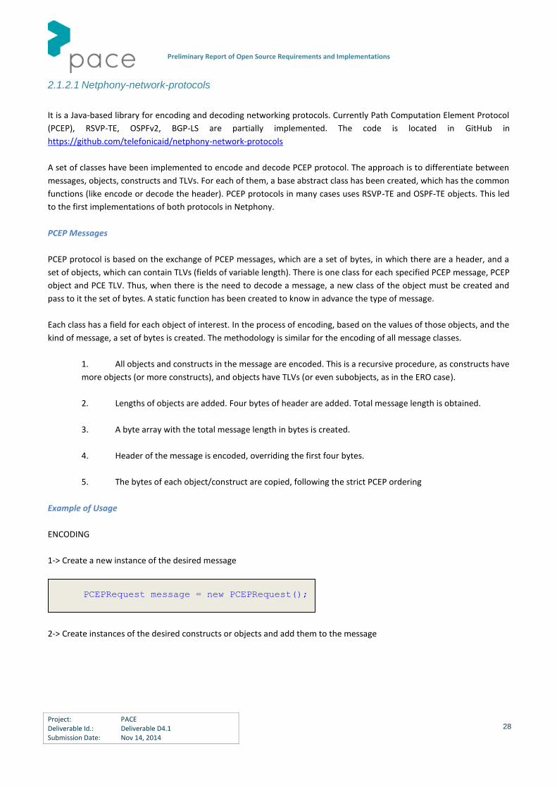
1-> Create a new instance of the desired message
2-> Create instances of the desired constructs or objects and add them to the message
PCEPRequest message = new PCEPRequest();

Preliminary Report of Open Source Requirements and Implementations
Project: PACE Deliverable Id.: Deliverable D4.1 Submission Date: Nov 14, 2014
29
3-> Call encode()
4-> Get bytes and send them
PCEP Support
RFC 5440: Full compliance
RFC 5521: Path-key not supported
RFC 5886: Full compliance
RFC 6006: Only P2MP END-POINTS Object for IPv4
draft-ietf-pce-gmpls-pcep-extensions-01
draft-ietf-pce-inter-layer-ext-05
draft-ietf-pce-hierarchy-extensions-01
draft-ietf-pce-stateful-pce-05
out.write(message.getBytes());
out.flush();
message.encode();
Request req = new Request();
//RequestParameters
RequestParameters rp= new
RequestParameters();
rp.setPbit(true);
rp.setRequestID(123);
rp.setPrio(1);
rp.setReopt(false);
rp.setBidirect(false);
rp.setLoose(false);
req.setRequestParameters(rp);
//EndPoints
EndPointsIPv4 ep=new EndPointsIPv4();
req.setEndPoints(ep);
.....
message.addRequest(req);

Preliminary Report of Open Source Requirements and Implementations
Project: PACE Deliverable Id.: Deliverable D4.1 Submission Date: Nov 14, 2014
30
draft-ietf-pce-pcep-stateful-pce-gmpls-00
draft-ietf-pce-pce-initiated-lsp-00
2.1.2.2 Netphony-topology
The topology component (see Figure 2-2) has two main functions: (1) Import the state information from the network and
(2) export such information to the elements that can consume it, such as PCE, VNTM or an ALTO server. There are several
means to update the information of the Topology module, either though protocols such as BGP with the Link State
Extensions (BGP-LS) or traditional Interior Gateway Protocols (IGP) such as OSPFv2, or through a RESTful interface. For
the latter case, until there is a standard Restful API to export topology, a proprietary communication through a web
service has been implemented. The module can be easily expanded to integrate RESTful APIs from different vendors.
The next figure shows the topology module architecture that has been implemented. The Traffic Engineering database is
maintained in a unique database. The database has several views (graphs), such as IP layer, transport layer, or the
interconnection between domains/layers. Traffic engineering parameters such as bandwidth, wavelength occupancy,
spectrum occupancy, etc can be set in the TED.
BGP-LS extends the BGP Update messages to advertise link-state topology thanks to new BGP Network Layer
Reachability Information (NLRI). In this section we explain how to build the BGP-LS Update messages that contain Inter-
domain and intra-domain LSAs. The Link State information is sent in two BGP attributes, the MP_REACH (defined in RFC
4670) and a LINK_STATE attribute (defined in the BGP-LS draft). To describe both the intra and inter domain links, in
the MP_REACH attribute, we use a Link NLRI, which contains in the local node descriptors the address of the source, and
in the remote descriptors, the address of the destination of the link. The Link Descriptors field has a TLV (Link
Local/Remote Identifiers), which carries the prefix of the Unnumbered Interface. In case of the message informs about
an intra-domain link, the standard traffic engineering information is included in the LINK_STATE attribute. In addition,
the Available Labels TLV is added to the LINK_STATE to include the availability of the frequency slots.
Figure 2-2 Netphony topology module.
Preliminary Report of Open Source Requirements and Implementations
Project: PACE Deliverable Id.: Deliverable D4.1 Submission Date: Nov 14, 2014
31
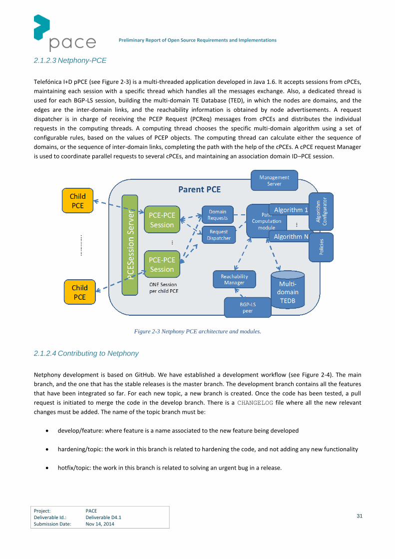
2.1.2.3 Netphony-PCE
Telefónica I+D pPCE (see Figure 2-3) is a multi-threaded application developed in Java 1.6. It accepts sessions from cPCEs,
maintaining each session with a specific thread which handles all the messages exchange. Also, a dedicated thread is
used for each BGP-LS session, building the multi-domain TE Database (TED), in which the nodes are domains, and the
edges are the inter-domain links, and the reachability information is obtained by node advertisements. A request
dispatcher is in charge of receiving the PCEP Request (PCReq) messages from cPCEs and distributes the individual
requests in the computing threads. A computing thread chooses the specific multi-domain algorithm using a set of
configurable rules, based on the values of PCEP objects. The computing thread can calculate either the sequence of
domains, or the sequence of inter-domain links, completing the path with the help of the cPCEs. A cPCE request Manager
is used to coordinate parallel requests to several cPCEs, and maintaining an association domain ID–PCE session.
Figure 2-3 Netphony PCE architecture and modules.
2.1.2.4 Contributing to Netphony
Netphony development is based on GitHub. We have established a development workflow (see Figure 2-4). The main
branch, and the one that has the stable releases is the master branch. The development branch contains all the features
that have been integrated so far. For each new topic, a new branch is created. Once the code has been tested, a pull
request is initiated to merge the code in the develop branch. There is a CHANGELOG file where all the new relevant
changes must be added. The name of the topic branch must be:
develop/feature: where feature is a name associated to the new feature being developed
hardening/topic: the work in this branch is related to hardening the code, and not adding any new functionality
hotfix/topic: the work in this branch is related to solving an urgent bug in a release.

Preliminary Report of Open Source Requirements and Implementations
Project: PACE Deliverable Id.: Deliverable D4.1 Submission Date: Nov 14, 2014
32
Figure 2-4 Netphony development workflow.
Periodically, after major changes or additions to the code in the development, a new release is produced.
2.1.3 Orange QUAGGA Extensions
In conjunction with section 1.2 that specifies the Traffic Engineering Database requirement for the PCE, we have
developed, at Orange Labs, some TE extensions to the Open Source Quagga. The Open Source project Quagga aims at
delivering an implementation of well-known routing protocols. Currently, Quagga supports RIP, RIPng, BGP, OSPF, IS-IS
and Babel. Each protocol runs as a standalone daemon. An additional daemon, named zebra (coming from the original
project Zebra from which Quagga forked) is in charge of communication between all routing protocol (for route re-
distribution) and the kernel space to manage interfaces and routing tables. Regarding Traffic Engineering, only OSPF
daemon provided a basic out of date support. The work done has been consisted to update the OSPF-TE support to latest
RFC, including the RFC5088 for PCE announcement and add basic TE support for IS-IS.
All code has been published under GitHub https://github.com/Orange-OpenSource/Quagga-TE as well as patches to raw
Quagga edition. The code has been reviewed by Quagga maintainers and corrections have been published. The code is
now ready for inclusion in the Quagga main stream.
The following sections provide documentation to compile Quagga and setup TE parameters for OSPF and IS-IS.
2.1.3.1 Installation
Three solutions are available to install Quagga-TE:
Clone this repository
Apply the quagga-git-te.diff patch on top of a fresh quagga source:
cd quagga
patch -p1 < TE-patches/quagga-git-te.diff Apply the quagga-0.99.23-te.diff patch on a latest 0.99.23 release:
tar xvf quagga-0.99.23.tar.gz
cd quagga-0.99.23
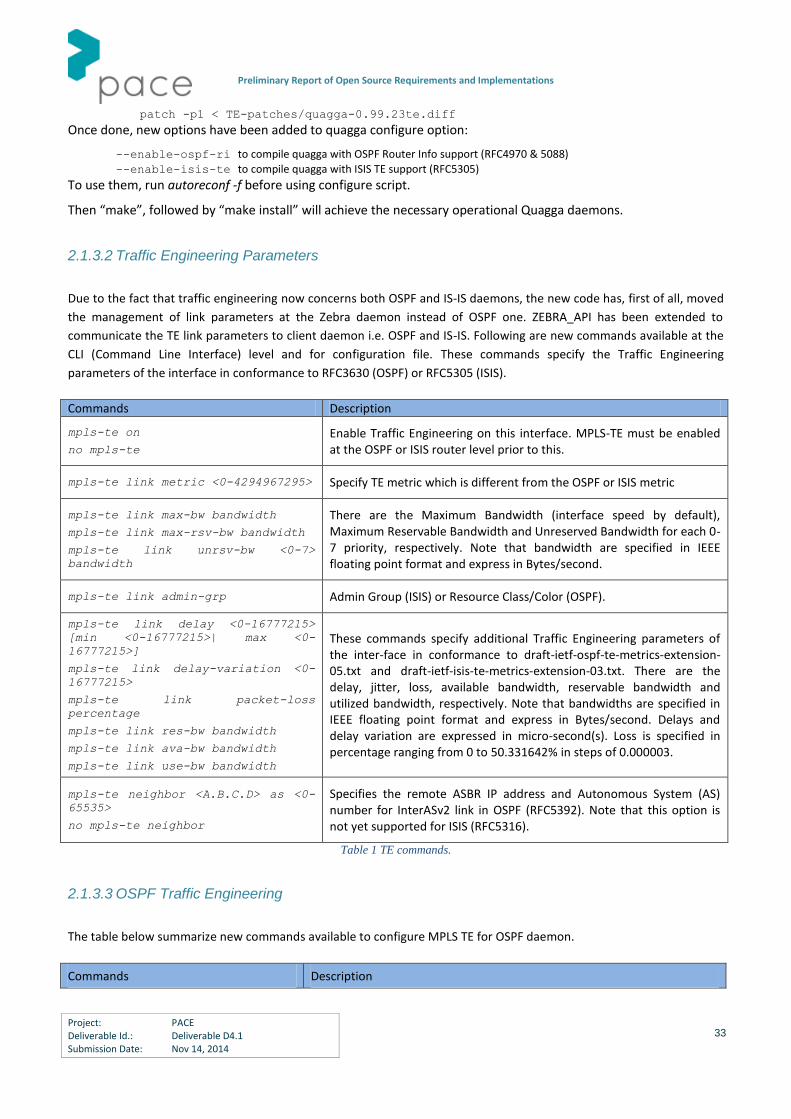
Preliminary Report of Open Source Requirements and Implementations
Project: PACE Deliverable Id.: Deliverable D4.1 Submission Date: Nov 14, 2014
33
patch -p1 < TE-patches/quagga-0.99.23te.diff Once done, new options have been added to quagga configure option:
--enable-ospf-ri to compile quagga with OSPF Router Info support (RFC4970 & 5088)
--enable-isis-te to compile quagga with ISIS TE support (RFC5305)
To use them, run autoreconf -f before using configure script.
Then “make”, followed by “make install” will achieve the necessary operational Quagga daemons.
2.1.3.2 Traffic Engineering Parameters
Due to the fact that traffic engineering now concerns both OSPF and IS-IS daemons, the new code has, first of all, moved
the management of link parameters at the Zebra daemon instead of OSPF one. ZEBRA_API has been extended to
communicate the TE link parameters to client daemon i.e. OSPF and IS-IS. Following are new commands available at the
CLI (Command Line Interface) level and for configuration file. These commands specify the Traffic Engineering
parameters of the interface in conformance to RFC3630 (OSPF) or RFC5305 (ISIS).
Commands Description
mpls-te on
no mpls-te
Enable Traffic Engineering on this interface. MPLS-TE must be enabled at the OSPF or ISIS router level prior to this.
mpls-te link metric <0-4294967295> Specify TE metric which is different from the OSPF or ISIS metric
mpls-te link max-bw bandwidth
mpls-te link max-rsv-bw bandwidth
mpls-te link unrsv-bw <0-7>
bandwidth
There are the Maximum Bandwidth (interface speed by default), Maximum Reservable Bandwidth and Unreserved Bandwidth for each 0-7 priority, respectively. Note that bandwidth are specified in IEEE floating point format and express in Bytes/second.
mpls-te link admin-grp Admin Group (ISIS) or Resource Class/Color (OSPF).
mpls-te link delay <0-16777215>
[min <0-16777215>| max <0-
16777215>]
mpls-te link delay-variation <0-
16777215>
mpls-te link packet-loss
percentage
mpls-te link res-bw bandwidth
mpls-te link ava-bw bandwidth
mpls-te link use-bw bandwidth
These commands specify additional Traffic Engineering parameters of the inter-face in conformance to draft-ietf-ospf-te-metrics-extension-05.txt and draft-ietf-isis-te-metrics-extension-03.txt. There are the delay, jitter, loss, available bandwidth, reservable bandwidth and utilized bandwidth, respectively. Note that bandwidths are specified in IEEE floating point format and express in Bytes/second. Delays and delay variation are expressed in micro-second(s). Loss is specified in percentage ranging from 0 to 50.331642% in steps of 0.000003.
mpls-te neighbor <A.B.C.D> as <0-
65535>
no mpls-te neighbor
Specifies the remote ASBR IP address and Autonomous System (AS) number for InterASv2 link in OSPF (RFC5392). Note that this option is not yet supported for ISIS (RFC5316).
Table 1 TE commands.
2.1.3.3 OSPF Traffic Engineering
The table below summarize new commands available to configure MPLS TE for OSPF daemon.
Commands Description

Preliminary Report of Open Source Requirements and Implementations
Project: PACE Deliverable Id.: Deliverable D4.1 Submission Date: Nov 14, 2014
34
mpls-te on
no mpls-te Enable Traffic Engineering LSA flooding.
mpls-te router-address
<A.B.C.D>
Configure stable IP address for MPLS-TE. This IP address is then advertised in Opaque LSA Type-10 TLV=1 (TE) option 1 (Router-Address)
mpls-te inter-as area <area-
id>|as
no mpls-te inter-as
Enable RFC5392 - Inter-AS TE v2 - to flood Traffic Engineering parameters of Inter-AS link. Two modes are supported: AREA and AS; LSA are flood in AREA <area-id> with Opaque Type-10, respectively in AS with Opaque Type-11. In all case, Opaque-LSA TLV=6.
show ip ospf mpls-te interface
show ip ospf mpls-te interface
interface
Show MPLS Traffic Engineering parameters for all or specified interface
Show ip ospf mpls-te router Show Traffic Engineering router parameters
Table 2 OSPF-TE daemon commands.
2.1.3.4 OSPF Router Information
The table below summarizes the new command for Router Information and PCE advertisement.
Commands Description
router-info [as | area
<A.B.C.D>]
no router-info
Enable Router Information (RI - RFC4970) LSA advertisement with AS scope (de-fault) or Area scope flooding when area is specified.
pce address <A.B.C.D>
no pce address
The commands are conform to RFC 5088 and allow OSPF router announce Path Computation Element (PCE) capabilities through the Router Information (RI) LSA. Router Information must be enabled prior to this. The command set/unset respectively the PCE IP address, Autonomous System (AS) numbers of controlled domains, neighbour ASs, flag and scope. For flag and scope, please refer to RFC5088 for the BITPATTERN recognition. Multiple ‘pce neighbour’ command could be specified in order to specify all PCE neighbours.
pce domain as <0-65535>
no pce domain as <0-65535>
pce neighbor as <0-65535>
no pce neighbor as <0-65535>
pce flag BITPATTERN
no pce flag
pce scope BITPATTERN
no pce scope
show ip ospf router-info Show Router Capabilities flag
show ip ospf router-info pce Show Router Capabilities PCE parameters
Table 3 OSPF information commands.
2.1.3.5 Configuration File Example
Zebra.conf
Configuration of interface with MPLS TE
hostname HOSTNAME
password PASSWORD
log file /var/log/zebra.log
!

Preliminary Report of Open Source Requirements and Implementations
Project: PACE Deliverable Id.: Deliverable D4.1 Submission Date: Nov 14, 2014
35
interface eth0
ip address 198.168.1.1/24
mpls-te on
mpls-te link metric 10
mpls-te link max-bw 1.25e+06
mpls-te link max-rsv-bw 1.25e+06
mpls-te link unrsv-bw 0 1.25e+06
mpls-te link unrsv-bw 1 1.25e+06
mpls-te link unrsv-bw 2 1.25e+06
mpls-te link unrsv-bw 3 1.25e+06
mpls-te link unrsv-bw 4 1.25e+06
mpls-te link unrsv-bw 5 1.25e+06
mpls-te link unrsv-bw 6 1.25e+06
mpls-te link unrsv-bw 7 1.25e+06
mpls-te link rsc-clsclr 0xab
!
interface eth1
ip address 192.168.2.1/24
mpls-te on
mpls-te link metric 10
mpls-te link max-bw 1.25e+06
mpls-te link max-rsv-bw 1.25e+06
mpls-te link unrsv-bw 0 1.25e+06
mpls-te link unrsv-bw 1 1.25e+06
mpls-te link unrsv-bw 2 1.25e+06
mpls-te link unrsv-bw 3 1.25e+06
mpls-te link unrsv-bw 4 1.25e+06
mpls-te link unrsv-bw 5 1.25e+06
mpls-te link unrsv-bw 6 1.25e+06
mpls-te link unrsv-bw 7 1.25e+06
mpls-te link rsc-clsclr 0xab
mpls-te neighbor 192.168.2.2 as 65000
Ospfd.conf
A router information example with PCE advertisement:
router ospf
ospf router-id 192.168.1.1
network 192.168.0.0/16 area 1
capability opaque
mpls-te
mpls-te router-address 192.168.1.1
router-info area 0.0.0.1
pce address 192.168.1.1
pce flag 0x80
pce domain as 65400
pce neighbor as 65500
pce neighbor as 65200
pce scope 0x80
!
2.1.3.6 IS-IS Traffic Engineering
The table below summarizes new commands available to configure MPLS TE for IS-IS daemon.
Commands Description
mpls-te on Enable Traffic Engineering LSP flooding.

Preliminary Report of Open Source Requirements and Implementations
Project: PACE Deliverable Id.: Deliverable D4.1 Submission Date: Nov 14, 2014
36
no mpls-te
mpls-te router-address <A.B.C.D>
no mpls-te router-address
Configure stable IP address for MPLS-TE. This IP address is then advertised in Opaque LSP Type-10 TLV=1 (TE) option 1 (Router-Address)
show mpls-te interface
show mpls-te interface <interface name>
Show MPLS Traffic Engineering parameters for all or specified interface
show mpls-te router Show Traffic Engineering router parameters
Table 4 IS-IS daemon commands.
Isisd.conf
A sample configuration for IS-IS with TE enable is hereafter reported:
hostname HOSTNAME
password PASSWORD
log file /var/log/isisd.log
!
!
interface eth0
ip router isis FOO
!
interface eth1
ip router isis FOO
!
!
router isis FOO
isis net 47.0023.0000.0000.0000.0000.0000.0000.1900.0004.00
mpls-te on
mpls-te router-address 10.1.1.1
!
line vty
2.2 Open Source Libraries and Tools
2.2.1 Javascript cne-tNetwork graph Visualization Library
TID has released a JavaScript visualization library to create and draw network graphs. It is SVG-based and HTML 5
compatible. This is a free library publicly available on github, licensed under the GNU Afferro license. It is available in
https://github.com/telefonicaid/cne-tnetwork.
2.2.1.1 Creating a network drawing
A html page that uses tNetwork should have to start working with tNetwork:
<html>
<head>
<script type="text/javascript"
src="http://code.jquery.com/jquery-latest.min.js"></script>
<link href="yourtnetworkpath/css/tNetwork.css" rel="stylesheet" type="text/css" />
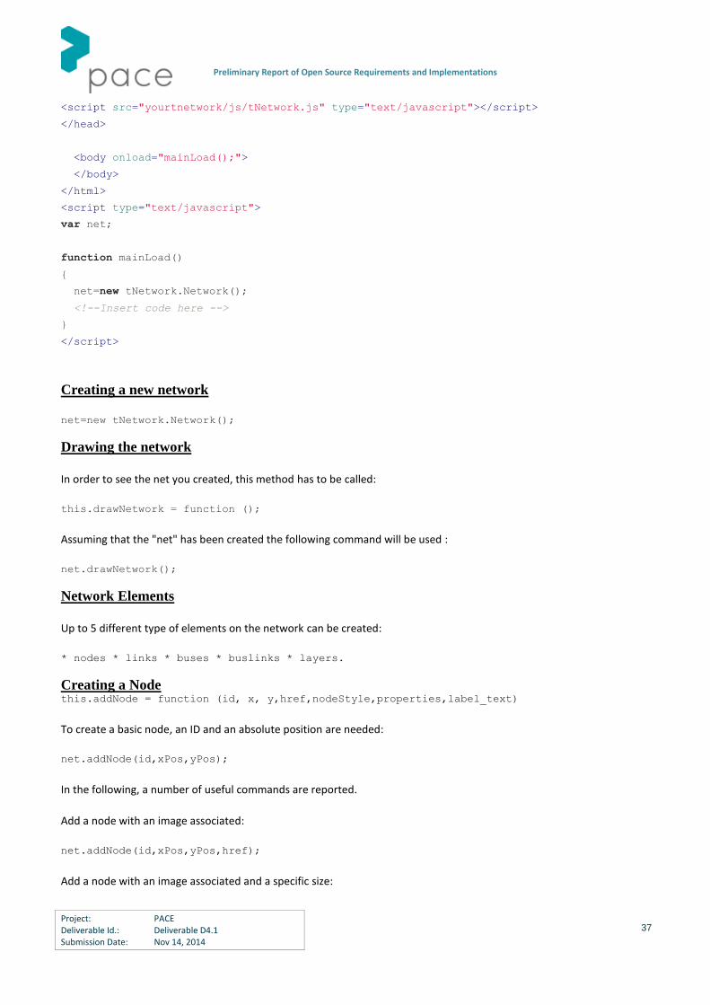
Preliminary Report of Open Source Requirements and Implementations
Project: PACE Deliverable Id.: Deliverable D4.1 Submission Date: Nov 14, 2014
37
<script src="yourtnetwork/js/tNetwork.js" type="text/javascript"></script>
</head>
<body onload="mainLoad();">
</body>
</html>
<script type="text/javascript">
var net;
function mainLoad()
{
net=new tNetwork.Network();
<!--Insert code here -->
}
</script>
Creating a new network
net=new tNetwork.Network();
Drawing the network
In order to see the net you created, this method has to be called:
this.drawNetwork = function ();
Assuming that the "net" has been created the following command will be used :
net.drawNetwork();
Network Elements
Up to 5 different type of elements on the network can be created:
* nodes * links * buses * buslinks * layers.
Creating a Node this.addNode = function (id, x, y,href,nodeStyle,properties,label_text)
To create a basic node, an ID and an absolute position are needed:
net.addNode(id,xPos,yPos);
In the following, a number of useful commands are reported.
Add a node with an image associated:
net.addNode(id,xPos,yPos,href);
Add a node with an image associated and a specific size:

Preliminary Report of Open Source Requirements and Implementations
Project: PACE Deliverable Id.: Deliverable D4.1 Submission Date: Nov 14, 2014
38
net.addNode(id,xPos,yPos,href,{width:100,height:100});
Add a node with properties that are displayed when you hover the mouse over the node:
net.addNode(id,xPos,yPos,"","",{p1:"address=192.168.1.1",p2:"id = node1"});
Add a node directly with a label:
net.addNode(id,xPos,yPos,"","","",label_text);
Creating a Layer:
this.addLayer = function (layer_id,height,y,fill,properties)
A layer is basically a huge rectangle. It is used to delineate parts of the network.
The basic use is:
net.addLayer(id,height,yPos)
In order to have a certain fill colour and properties of the layer :
net.addLayer(id,height,yPos,"####BBBBBB",{p1:"subnet layer",p2:"represents the subnet"});
Creating a Link:
this.addLink = function (source, destination, bidirectional,style,properties,label_text)
Once at least two nodes are created, a basic link between them can be created.
net.addLink(idSourceNode,idDestNode);
If the link is required not to end with an arrow:
net.addLink(idSourceNode,idDestNode,true);
Adding a link with a specific width and/or color:
net.addLink(idSourceNode,idDestNode,"",{color:"FFFFFF",width:20});
Creating a Bus:
this.addVerticalBus = function (bus_id,x,min_height,style,properties,label_text)
To create a bus with linked nodes, it is necessary to create a bus first.
How to create a basic bus:
net.addBus(bus_id,xPos);
Then, links can be created :
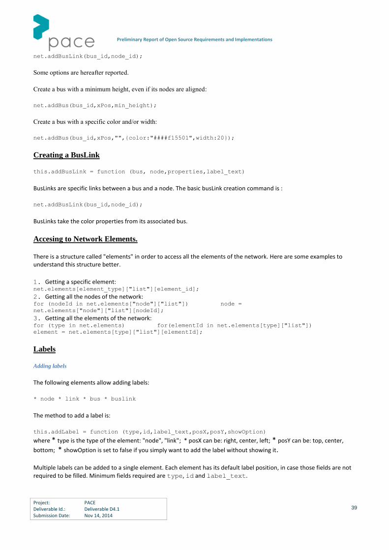
Preliminary Report of Open Source Requirements and Implementations
Project: PACE Deliverable Id.: Deliverable D4.1 Submission Date: Nov 14, 2014
39
net.addBusLink(bus_id,node_id);
Some options are hereafter reported.
Create a bus with a minimum height, even if its nodes are aligned:
net.addBus(bus_id,xPos,min_height);
Create a bus with a specific color and/or width:
net.addBus(bus_id,xPos,"",{color:"####f15501",width:20});
Creating a BusLink
this.addBusLink = function (bus, node,properties,label_text)
BusLinks are specific links between a bus and a node. The basic busLink creation command is :
net.addBusLink(bus_id,node_id);
BusLinks take the color properties from its associated bus.
Accesing to Network Elements.
There is a structure called "elements" in order to access all the elements of the network. Here are some examples to understand this structure better.
1. Getting a specific element: net.elements[element_type]["list"][element_id];
2. Getting all the nodes of the network: for (nodeId in net.elements["node"]["list"]) node =
net.elements["node"]["list"][nodeId];
3. Getting all the elements of the network: for (type in net.elements) for(elementId in net.elements[type]["list"])
element = net.elements[type]["list"][elementId];
Labels
Adding labels
The following elements allow adding labels:
* node * link * bus * buslink
The method to add a label is:
this.addLabel = function (type,id,label_text,posX,posY,showOption)
where * type is the type of the element: "node", "link"; * posX can be: right, center, left; * posY can be: top, center,
bottom; * showOption is set to false if you simply want to add the label without showing it.
Multiple labels can be added to a single element. Each element has its default label position, in case those fields are not required to be filled. Minimum fields required are type, id and label_text.
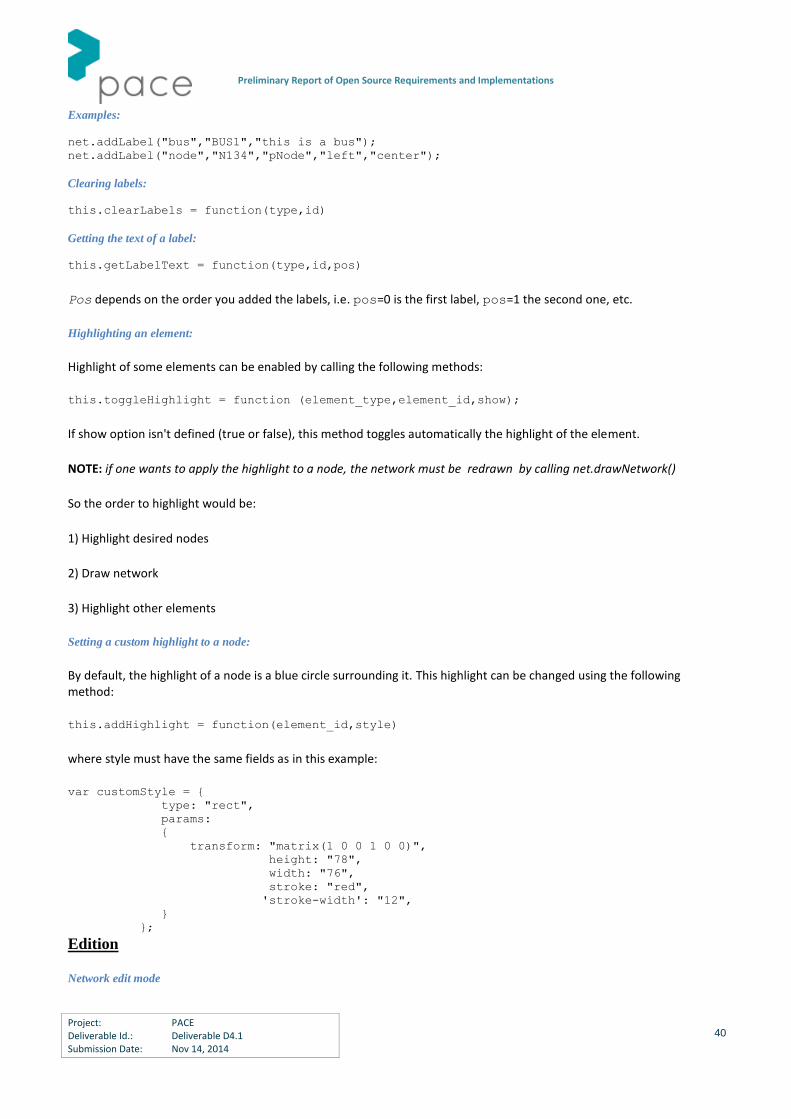
Preliminary Report of Open Source Requirements and Implementations
Project: PACE Deliverable Id.: Deliverable D4.1 Submission Date: Nov 14, 2014
40
Examples:
net.addLabel("bus","BUS1","this is a bus"); net.addLabel("node","N134","pNode","left","center");
Clearing labels:
this.clearLabels = function(type,id)
Getting the text of a label:
this.getLabelText = function(type,id,pos)
Pos depends on the order you added the labels, i.e. pos=0 is the first label, pos=1 the second one, etc.
Highlighting an element:
Highlight of some elements can be enabled by calling the following methods:
this.toggleHighlight = function (element_type,element_id,show);
If show option isn't defined (true or false), this method toggles automatically the highlight of the element.
NOTE: if one wants to apply the highlight to a node, the network must be redrawn by calling net.drawNetwork()
So the order to highlight would be:
1) Highlight desired nodes
2) Draw network
3) Highlight other elements
Setting a custom highlight to a node:
By default, the highlight of a node is a blue circle surrounding it. This highlight can be changed using the following method:
this.addHighlight = function(element_id,style)
where style must have the same fields as in this example:
var customStyle = {
type: "rect",
params:
{
transform: "matrix(1 0 0 1 0 0)",
height: "78",
width: "76",
stroke: "red",
'stroke-width': "12",
}
};
Edition
Network edit mode

Preliminary Report of Open Source Requirements and Implementations
Project: PACE Deliverable Id.: Deliverable D4.1 Submission Date: Nov 14, 2014
41
These methods are used to start or stop the network edit mode:
this.startEditMode = function (); this.stopEditMode = function ();
When the network is in edit mode, the following actions can be performed:
- Move the network nodes and buses through its container by clicking on them and dragging,
- Move the entire network by clicking inside the container and moving the mouse,
- Changing network's size by scrolling inside the container.
NOTE: if the network isn't in a specific container, the actions can be done in the whole page.
Hiding/Showing elements
this.hideElement = function(id,type,element) this.showElement = function(id,type,element)
The element can be found through one of these three combinations:
id+type: net.showElement("node1","node");
id: net.showElement("node1");
element net.showElement("","",node1);
There are certain elements that are automatically shown/hidden when hiding other ones. For example, if a node is hidden, its labels and associated links will be hidden as well.
NOTE: in order to apply changes, the network must be drawn again.
2.2.1.2 Examples
The javascript cne-tNetwork library has been used in the XIFI project in the GUI of the inter-datacenter tool. A couple of
examples are shown below about the kind of drawings that can be done with the tool.
Figure 2-5 cne-tNetwork: example 1.
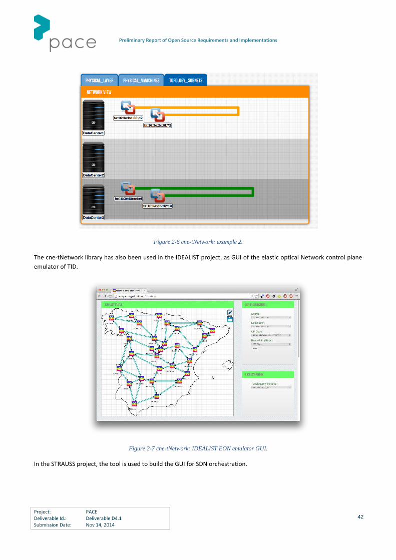
Preliminary Report of Open Source Requirements and Implementations
Project: PACE Deliverable Id.: Deliverable D4.1 Submission Date: Nov 14, 2014
42
Figure 2-6 cne-tNetwork: example 2.
The cne-tNetwork library has also been used in the IDEALIST project, as GUI of the elastic optical Network control plane
emulator of TID.
Figure 2-7 cne-tNetwork: IDEALIST EON emulator GUI.
In the STRAUSS project, the tool is used to build the GUI for SDN orchestration.
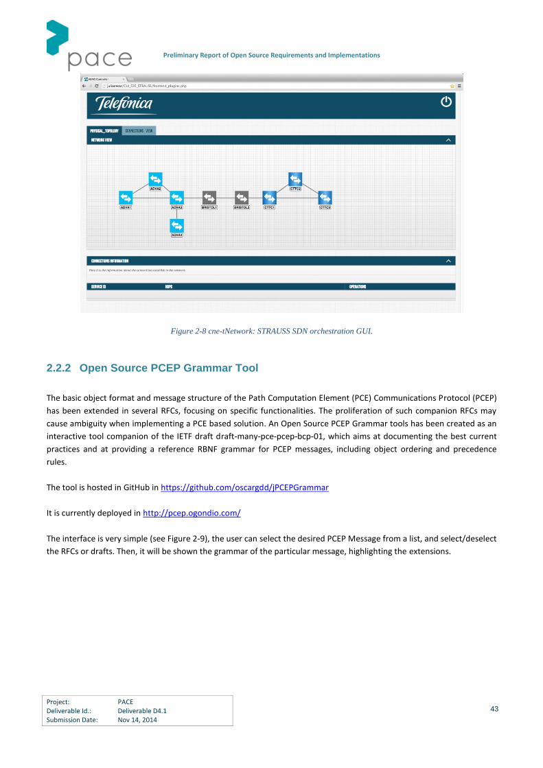
Preliminary Report of Open Source Requirements and Implementations
Project: PACE Deliverable Id.: Deliverable D4.1 Submission Date: Nov 14, 2014
43
Figure 2-8 cne-tNetwork: STRAUSS SDN orchestration GUI.
2.2.2 Open Source PCEP Grammar Tool
The basic object format and message structure of the Path Computation Element (PCE) Communications Protocol (PCEP)
has been extended in several RFCs, focusing on specific functionalities. The proliferation of such companion RFCs may
cause ambiguity when implementing a PCE based solution. An Open Source PCEP Grammar tools has been created as an
interactive tool companion of the IETF draft draft-many-pce-pcep-bcp-01, which aims at documenting the best current
practices and at providing a reference RBNF grammar for PCEP messages, including object ordering and precedence
rules.
The tool is hosted in GitHub in https://github.com/oscargdd/jPCEPGrammar
It is currently deployed in http://pcep.ogondio.com/
The interface is very simple (see Figure 2-9), the user can select the desired PCEP Message from a list, and select/deselect
the RFCs or drafts. Then, it will be shown the grammar of the particular message, highlighting the extensions.
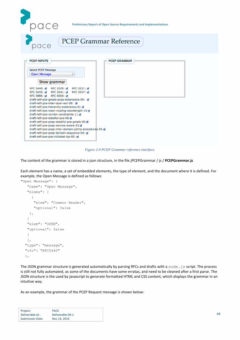
Preliminary Report of Open Source Requirements and Implementations
Project: PACE Deliverable Id.: Deliverable D4.1 Submission Date: Nov 14, 2014
44
The content of the grammar is stored in a json structure, in the file jPCEPGrammar / js / PCEPGrammar.js
Each element has a name, a set of embedded elements, the type of element, and the document where it is defined. For example, the Open Message is defined as follows:
"Open Message": {
"name": "Open Message",
"elems": [
{
"elem": "Common Header",
"optional": false
},
{
"elem": "OPEN",
"optional": false
}
],
"type": "message",
"rfc": "RFC5440"
},
The JSON grammar structure is generated automatically by parsing RFCs and drafts with a node.js script. The process is still not fully automated, as some of the documents have some erratas, and need to be cleaned after a first parse. The JSON structure is the used by javascript to generate formatted HTML and CSS content, which displays the grammar in an intuitive way.
As an example, the grammar of the PCEP Request message is shown below:
Figure 2-9 PCEP Grammar reference interface.

Preliminary Report of Open Source Requirements and Implementations
Project: PACE Deliverable Id.: Deliverable D4.1 Submission Date: Nov 14, 2014
45
Figure 2-10 Example of PCEP PCReq.
2.3 PCE as a Service: Open Source Path Computation
Evaluation
Path Computation Evaluation Service is conceived to allow third party evaluation of Open Source path computation
algorithms within a real PCE. The SSSA path computation element prototype has been implemented to experimentally
validate interoperability in multi-platform, multi-domain and multi-partner scenarios, along with the evaluation of PCEP
extensions and novel PCE-based procedures and architectures proposed in the context of optical networks (mainly
WSON and EON).
Path Computation Evaluation Service will offer the opportunity to test and evaluate path computation algorithms in a
configurable real EON scenario. PCE will directly interact with the SSSA testbed, made of an EON-enabled mesh GMPLS
network.
Simple API will be available in order to easily compile external Open Source algorithms within the PCE. Internal TED and
LSP-DB database will be available as input information source under the form of the reference YANG models described in
Section 1.
The architecture of the PCE hosting Open Source path computation algorithms is depicted in Figure 2-11.

Preliminary Report of Open Source Requirements and Implementations
Project: PACE Deliverable Id.: Deliverable D4.1 Submission Date: Nov 14, 2014
46
Active Stateful PCE
Stateful DB
TED DB
ActiveSolver
ActionHandler
PCEP server Actions
queue
PCalgorithm TED /
StatefulYANG model
interface
Figure 2-11 PCE as a service. Internal architecture of PCE.
Active stateful PCE is considered, including TED and LSP-DB (Stateful DB). A dedicated interface makes updated
databases information available under the form of XML-based YANG-compatible structure.
The evaluation of the path computation algorithm will include the path computation time, the average CPU and RAM
load and the network utilization achieved by the algorithm.
The PCE Evaluation service architecture is in the development stage and will be available in the second year of the PACE
project.
2.4 Open Source PCEP Dissector
In the context of the well-known Open Source Wireshark protocol analyzer [WIRESHARK], TID and SSSA have extended
the official PCEP dissector in order to include PCEP extensions currently not supported by the analyzer. The availability of
an official PCEP dissector fully updated with the most interesting extensions proposed by the latest IETF RFCs (and most
promising drafts) is of great importance and help for all PCE developers in experimental activities involving the PCEP
protocol.
The first PCEP extension release fully covers the point-to-multipoint extensions standardized for PCEP [RFC6006]. The
extended C-based dissector has been tested with capture files obtained by a joint Telefonica-UPC-SSSA testbed
employing P2MP PCEP. Official patch is going to be submitted to Wireshark git repository for test and approval. The two
captures shown in Figure 2-12 and Figure 2-13 detail some of the new dissected PCEP objects. In particular in the PCReq
supports the extended ENDPOINTS including multiple destinations, while the PCRep supports the Secondary ERO (SERO)
object and the UNREACH object.

Preliminary Report of Open Source Requirements and Implementations
Project: PACE Deliverable Id.: Deliverable D4.1 Submission Date: Nov 14, 2014
47
Figure 2-12 Wireshark PCEP dissector: PCReq with P2MP LSP request.
Figure 2-13. Wireshark PCEP dissector: PCRep with ERO and SERO.
2.5 Open Source PCE Simulators
SSSA proposes an implementation of a PCE and GMPLS simulator based on the OPNET Modeler framework.

Preliminary Report of Open Source Requirements and Implementations
Project: PACE Deliverable Id.: Deliverable D4.1 Submission Date: Nov 14, 2014
48
OPNET is a structured event driven network simulator. Its framework offers the tools for model design, simulation, statistics data collection and analysis. OPNET has been specifically designed for the simulation of complex networks. Moreover, the framework creates an abstraction layer that allows the developer to concentrate on the programming of the specific nodes and protocols. Whilst the environment implementation, such as the communication between nodes, links and packet format definition,
is already built in the framework and can be managed through the OPNET graphical user interface. OPNET Modeler is a professional tool used under license by companies and fortunately, it is free for academic and research purposes. However, all the libraries and extensions provided by SSSA will be completely free to install, use and modify.
2.5.1 PCE Extensions in OPNET Simulator
Our implementation is composed of different blocks. In particular:
Protocol Modules:
- OSPF-TE
- RSVP-TE
- PCEP
- TCP
Databases:
- TED
Figure 2-14 OPNET Modeler.
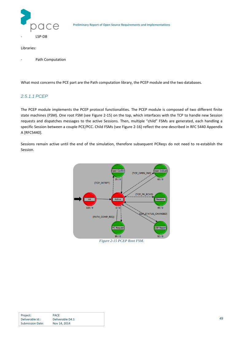
Preliminary Report of Open Source Requirements and Implementations
Project: PACE Deliverable Id.: Deliverable D4.1 Submission Date: Nov 14, 2014
49
- LSP-DB
Libraries:
- Path Computation
What most concerns the PCE part are the Path computation library, the PCEP module and the two databases.
2.5.1.1 PCEP
The PCEP module implements the PCEP protocol functionalities. The PCEP module is composed of two different finite
state machines (FSM). One root FSM (see Figure 2-15) on the top, which interfaces with the TCP to handle new Session
requests and dispatches messages to the active Sessions. Then, multiple “child” FSMs are generated, each handling a
specific Session between a couple PCE/PCC. Child FSMs (see Figure 2-16) reflect the one described in RFC 5440 Appendix
A [RFC5440].
Sessions remain active until the end of the simulation, therefore subsequent PCReqs do not need to re-establish the
Session.
Figure 2-15 PCEP Root FSM.

Preliminary Report of Open Source Requirements and Implementations
Project: PACE Deliverable Id.: Deliverable D4.1 Submission Date: Nov 14, 2014
50
Figure 2-16 PCEP Child FSM.
The implemented PCReq contains:
- End-points object (source and destination addresses).
- RP Object
- Bandwidth Object
- PC Params Object
The bandwidth object in our case refers to the capacity in Gbps requested by the PCC.
The Path Computation (PC) Params Object contains the Metric and other parameters useful for the path computation
that will be described later in the Path Computation Library section.
The implemented PCRep contains:
- RP Object
- No Path Object
- List of LSP Objects
Instead of list of paths, a list of LSP objects is returned in order to support the slice-ability functionality. If multiple LSPs
Objects are returned it means that the slice-ability has been applied, therefore the traffic demand will be served by
multiple LSPs. To associate the path with the LSP, the ERO object is inserted inside the LSP Object.
Preliminary Report of Open Source Requirements and Implementations
Project: PACE Deliverable Id.: Deliverable D4.1 Submission Date: Nov 14, 2014
51
The PCE has been designed to support different types of transponders and to distinguish among them. For this reason,
we extended the LSP Object with some additional information:
- List of Carriers: The list of central frequencies each associated to a different carrier of the transponder.
- Ingress TX Transponder: Identifies the transponder to use as transmitter at the ingress node.
- Ingress RX Transponder: Identifies the transponder to use as receiver at the ingress node.
- Egress TX Transponder: Identifies the transponder to use as transmitter at the egress node.
- Egress RX Transponder: Identifies the transponder to use as receiver at the egress node.
Users interface allows to configure the following parameters:
- PCE Address: the IP address of the PCE.
- Keepalive: Minimum period between the sending of PCEP messages (Keepalive, PCReq, PCRep, PCNtf) to a
PCEP peer in seconds; default is 30 seconds.
- Deadtimer: Period of time after which a PCEP peer declares the session down, if no PCEP message has been
received; default is four times the Keepalive.
- Stateful PCE: When true the stateful functionalities are enabled.
- Provisioning Path Computation Params: Parameters used by the path computation during provisioning.
- Recovery Path Computation Params: Parameters used by the path computation during recovery.
2.5.1.2 Path Computation Library
The path computation algorithm depends on the parameters passed to the path computation function.
The path computation parameters are the following:
- Metric: Could be “shortest path” or “least congested path among shortest + n”, where n is a configurable
parameter representing the additional hops from the shortest.
- Slice-ability: Could be “disabled”, “max slice” where the traffic demand is subdivided into multiple LSPs based on
the minimum traffic demand, or, “adaptive slice” where the traffic demand is recursively subdivided only if it cannot fit a
single LSP. When the slice-ability is enabled, another parameter specifies whether partial traffic allocation is allowed or
not.

Preliminary Report of Open Source Requirements and Implementations
Project: PACE Deliverable Id.: Deliverable D4.1 Submission Date: Nov 14, 2014
52
- Suggested Label: Specifies the allocation policy used during the path computation. Could be “disabled”, “first
fit”, “last fit”, or “random”.
Currently two different branches of algorithms are implemented that in the next future will be merged into one. Both
branches supports different metrics and different allocation policies according to the previously defined parameters. The
first branch supports slice-ability functionalities, while it does not consider the transponders. The second branch
supports the different types of transponders, but does not support the slice-ability.
2.5.1.3 TED
The Traffic Engineering Database implementation contains the topology information, i.e. nodes and edges composing the
topology graph, plus additional information useful for traffic engineering purposes.
In particular, a node is characterized by:
- Router ID: An address associated to the node, usually the loopback IP address.
- List of Transponders: A list of all the transponders of the node.
For each transponder, the following information are stored:
- ID: A unique identifier of the transponder.
- Type: Type of transponder. Up to now Multi-lasers SBVT, Multi-wavelengths SBVT with variable carrier spacing,
and, Multi-wavelengths SBVT with fixed carrier spacing are supported.
- Number of carriers: The maximum number of carriers the transponder can generate.
- List of Carriers.
- Max spacing: the maximum spacing among carriers.
- Min spacing: the minimum spacing among carriers.
Edges are characterized by:
- List of Free Slots: The list of available spectrum slots described by lower and upper frequency indexes.
- Failure: Boolean indicating if the link is broken.
The TED is kept up to date through the OSPF-TE protocol.

Preliminary Report of Open Source Requirements and Implementations
Project: PACE Deliverable Id.: Deliverable D4.1 Submission Date: Nov 14, 2014
53
2.5.1.4 LSP-DB
When Stateful PCE functionalities are enabled, the LSP-DB stored inside the PCE node is used to keep track of the LSPs
lifetime.
The information we store inside the LSP-DB are:
- Session Object: Identifies the LSP
- ERO Object: List of traversed nodes.
- Frequency Slot: The amount of spectrum occupied by the LSP described by lower and upper frequency indexes
- Carriers: List of carriers used by the LSP with the corresponding central frequency.
- Ingress TX Transponder: Identifies the transponder used as transmitter at the ingress node.
- Ingress RX Transponder: Identifies the transponder used as receiver at the ingress node.
- Egress TX Transponder: Identifies the transponder used as transmitter at the egress node.
- Egress RX Transponder: Identifies the transponder used as receiver at the egress node.
2.6 Experimental Collaborative Platform
This section details common activities taking place both in Tasks T3.3 and T4.3. T3.3, “Experimental Collaboration
Platform”, addresses logical interconnections of existing testbeds via the public Internet for joint cross-project
experimentation and validation, e.g. a federation of existing system efforts based on very rich existing PCE
implementations and testbeds of most of the consortium members, including both proprietary as well as Open Source
testbeds, and open to third parties. The use of the infrastructure by a third-party involves connecting to the rest of the
partners via tunnels techniques (IPsec, IP GRE, GRE TAP …), assuming, for example, IP/TCP and PCEP connectivity. It
enables an agreed-upon and common understanding of the PCE protocol and (prioritized) features, based on actual
implementations and potentially resulting in implementation agreements and notes on agreed interpretations of existing
standards. Likewise, the task targets the deployment of a federated/joint testbed, facilitating the joint realization (cross-
project) of demonstrations.
Likewise, Task 4.3 will coordinate the experimental implementation and testing of Open Source tools. Following the
requirements output provided by Task 4.1, implemented PCE/SDN tools/components can be validated. On these lines
and related to the availability of Open Source implementations and tools, the federated infrastructure is available to be
used to test the aforementioned components. For this activity, a first initial milestone, M10, is achieved when the initial
design of the experimental platform is complete, specifying how the different partners testbeds are to be inter-
connected, which private IP addresses are allocated to each partner and what (underlying) topology is deployed. A
preliminary deployment of the infrastructure is complete, including exhaustive tests to validate partner connectivity,
notably at the PCEP level. At the time of writing, this milestone is complete.

Preliminary Report of Open Source Requirements and Implementations
Project: PACE Deliverable Id.: Deliverable D4.1 Submission Date: Nov 14, 2014
54
As of now, the experimental platform is up and running, being used in the context of PACE and other research projects.
Persistent IPSec tunnels with CTTC, Telefonica, SSSUP, Telecom Italia, NextWorks and UPC are active and being used (see
Figure 2-17). Tests cover basic PCEP and BGP-LS implementations and, recently, stateful PCE capabilities.
IPSEC Gateway
IPSEC Gateway
Internet Connectivity
CTTC Testbed IPSEC
Gateway
PartnerTestbed
PartnerTestbed
Figure 2-17 IPSec Hub connectivity using CTTC gw as hub.
In the following, we report the actual testbed interconnection for the realization of joint experiments and
demonstrations. The process has been designed to be relatively simple:
A first or third party needs to provide the (public) IP address of one’s IPsec gateway and a pre-shared key. Most
partners are using a Linux operating system with racoon IPSec software. It is possible that the party needs to
contact the IT dept. so a firewall rule allows incoming and outgoing IP (ISAKMP, etc.) and IPsec traffic.
CTTC IPSec gateway is acting as main hub. The public IP address is 84.88.62.99.
All partners have addresses with prefix 172.16.X.Y, where X is per partner (e.g. CTTC 102, TID 104, Orange is
110) and Y is within the party domain (e.g. CTTC has a PCE running at 172.16.102.201).
In the local configuration, the process is as follows:
The Pre-shared key (PSK) will need to appear in /etc/racoon/psk.txt
In the file /etc/racoon/racoon.conf the party needs to configure the remote IPsec gateway as shown below
(showing example for Telefonica).
path pre_shared_key "/etc/racoon/psk.txt";
listen
{
isakmp 84.88.62.99 [500];
}
# TID
remote 193.145.240.7 {
exchange_mode main, aggressive;

Preliminary Report of Open Source Requirements and Implementations
Project: PACE Deliverable Id.: Deliverable D4.1 Submission Date: Nov 14, 2014
55
my_identifier address 84.88.62.99;
initial_contact on;
proposal {
encryption_algorithm 3des;
hash_algorithm sha1;
authentication_method pre_shared_key;
dh_group 2;
}
}
# All peers share the same configuration
sainfo anonymous {
pfs_group 2;
encryption_algorithm 3des;
authentication_algorithm hmac_sha1, hmac_md5 ;
compression_algorithm deflate;
lifetime time 8 hour;
# lifetime byte 10000 Kb ;
}
The next step is to setup security policies e.g. in /etc/ipsec-tools.conf Again, as an example, for Telefonica, CTTC hub adds
spdadd 172.16.102.0/24 172.16.104.0/24 any -P out ipsec
esp/tunnel/84.88.62.99-193.145.240.7/require;
spdadd 172.16.104.0/24 172.16.102.0/24 any -P in ipsec
esp/tunnel/193.145.240.7-84.88.62.99/require;
The figure below (Figure 2-18) shows an example of emulated TED that is being currently used in the shared
infrastructure.
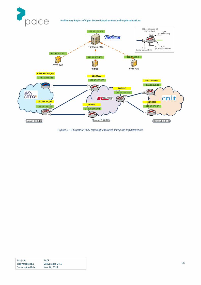
Preliminary Report of Open Source Requirements and Implementations
Project: PACE Deliverable Id.: Deliverable D4.1 Submission Date: Nov 14, 2014
56
TID Parent PCE
TI PCE
CTTC PCE
CNIT PCE
172.16.102.101
172.16.101.3
172.16.104.201
172.16.105.103
172.16.p.h: node_id
(partner, host)
x
y
if_id
(to intradomain link)
1z
if_id
(to inter-domain link)
172.16.102.106
BARCELONA_06
172.16.102.109
VALENCIA_09
11 11
12
11 11
12
172.16.105.105
GENOVA
172.16.105.102
ROMA
11
11
172.16.101.11
STUTTGART
172.16.101.10
MUNICH
172.16.105.106
TORINO
11
12
Domain 0.0.0.102 Domain 0.0.0.105 Domain 0.0.0.101
2ab
if_id
(to transceiver)
Figure 2-18 Example TED topology emulated using the infrastructure.

Preliminary Report of Open Source Requirements and Implementations
Project: PACE Deliverable Id.: Deliverable D4.1 Submission Date: Nov 14, 2014
57
3 PACE Instruments for Open Source Dissemination
In this chapter, the main dissemination instruments utilized by the PACE project with focus on Open Source activities are
reported. Three types of instruments have been adopted by the consortium: the Open Source forum, the Open Source
repository and the PACE workshops.
3.1 Open Source Forum
The Open Source forum in PACE comprises of several segments, such as the public mailing list (for expert advice on PCE-
related queries from PACE consortium), the public wiki (a living PCE documentation based on community initiatives),
Open Source repository (see Section 3.2) and the Open Source sessions and workshops in upcoming PACE workshops.
Also, efforts to conduct remote workshop among Open Source PCE developers is currently underway.
3.2 Open Source Repository
The Open Source repository in PACE is hosted on Github and presently includes one Open Source PCE implementation by
TUBS. Orange also recently published on Github their Open Source Quagga extensions. Another Open Source PCE
implementation is soon to be added to this repository by TID. In addition, an Open Source javascript-based graph
visualization library was recently released by TID on Github.
In the pipeline are efforts to shape this repository as an Open Source plugin marketplace for PCE.
Quagga extensions are available in GitHub repository at http://github.com/OrangeOpenSource/Quagga-TE and will be
incorporated in the next major release of Quagga http://www.quagga.org. Both code, documentation and patches are
available.

Preliminary Report of Open Source Requirements and Implementations
Project: PACE Deliverable Id.: Deliverable D4.1 Submission Date: Nov 14, 2014
58
3.3 Open Source Workshops
PACE Workshops that will be held in the PACE second year will have a dedicated focus on Open Source activities,
particularly, the PACE Workshop organized by TID (Madrid, Spain, January 2015) and the PACE Workshop co-located with
ONDM 2015 organized by SSSA (Pisa, Italy, May 2015).
3.3.1 TID Workshop
The next PACE workshop will be held in TID, Madrid, Spain on Feb 17-18, 2015. The workshop sets the goal of
concentrating researchers, developers, and standardization leaders in the area of Path Computation Element (PCE)
architectures, an Internet Engineering Task Force standard framework. The purpose is to gather and establish a forum of
world-leading thinkers, concentrated developers and all PCE enthusiasts, determined to rapidly facilitate the
commercialization of advanced Internet technology, infrastructure and applications, and help software defined
networking reach its full potential. Within the scope of the workshop is also an in-depth discussion on the value of Open
Source software, documentation and data repository. The findings and recommendations in the workshop will be written
in form of a report, encompassing a number of related subjects including the vision for future research and
standardization activities. The proposed workshop will promote the culture of visionary research and technology
innovation and high-tech talent in Europe, as well as globally. The workshop is expected not only to gather, but also
sustain a best-of-breed think-tank of leaders in this field, and more importantly, a community-led platform for innovation
in network engineering and science. While all elements of this workshop come from focused disciplinary areas of
emphasis, i.e. from a range of perspectives in Internet architectures, protocols, software engineering, or security, we see
these perspectives as an opportunity that the resulting research vision will promote research across these disciplines
with a whole-greater-than-sum-of-parts expectation.
The tentative panels and corresponding break-out sessions are proposed as follows, but are open to discussions and
changes:
Application Domain Areas, including
o Software Defined Networking (SDN)
o Core packet Internet, Mobile and mobile backhaul networks
o Cloud computing networks
o Content Distribution Networks (CDN)
o Next generation fiber optic networks
o Wireless sensor and mesh networks, Internet of Things (IoT)
Benefits from commonalities in algorithms across problem spaces
The role of Open Source

Preliminary Report of Open Source Requirements and Implementations
Project: PACE Deliverable Id.: Deliverable D4.1 Submission Date: Nov 14, 2014
59
The purpose, value, and plans for standardization
Outreach and Community Work, including
o Interoperability testing
o Joint experimentation ideas
o Integration in education of future workforce
Topics of discussion will include, and are not limited to:
How to architect future networks with PCE and related protocols and network management subsystems?
What are the research challenges in domain areas of data, content, and wireless cellular and sensor
technologies used in cyber physical systems?
What are the future applications and how can PCE help SDN fully succeed in legacy and open network
environments? Which security and privacy considerations are needed to assess these applications?
What are the software engineering principles in developing PCE-based architectures?
How can the community assist EU and other funding bodies to increase the research impact and visibility in this
area?
What are the next short-term and long terms needs and steps? How can they be identified?
How can the vision of the industrial and academic community be best articulated?
3.3.2 SSSA Workshop co-located with ONDM
The Workshop will be held in Pisa embedded within ONDM 2015 (official website ondm15.sssup.it). Dedicated half-day
will be slotted, in order to ensure attendance of ONDM conference participants. The workshop will host presentations of
both invited external speakers and PACE partners. Focus will be given to two topics: 1) New uses of PCE in the context of
emerging optical network and technologies, and, 2) advances in Open Source PCE /SDN framework. The workshop
organization, in parallel with ONDM conference organization, is in progress. More details about the program and the
speakers will be available in the next few months.

Preliminary Report of Open Source Requirements and Implementations
Project: PACE Deliverable Id.: Deliverable D4.1 Submission Date: Nov 14, 2014
60

Preliminary Report of Open Source Requirements and Implementations
Project: PACE Deliverable Id.: Deliverable D4.1 Submission Date: Nov 14, 2014
61
4 Conclusions
This deliverable has described the Open Source activities carried on in the first year of the PACE projects. Fruitful
collaboration among PACE partners has allowed the definition of the main Open Source requirements in terms of
reference architectures, information models and performance metrics. Under this important reference umbrella, the
PACE project has started to promote and disseminate the use of the PCE-based architectures though a wide set of Open
Source software instruments made available by the PACE partners. PCE emulators, libraries, dissectors for network
analyzers, PCE evaluation service, simulator extensions and other tools have been presented in this deliverable. Such
instruments will be disseminated, utilized, tested and evaluated in the second year of the PACE project. The aim of this
wide collaborative platform is to encourage collaboration, initiatives and activities among PACE partners and external
entities, both academic and industrial, in the general framework of promoting the PCE and PCE-related knowledge,
understanding, application in the most relevant European and worldwide scientific, industrial and standardization
communities.

Preliminary Report of Open Source Requirements and Implementations
Project: PACE Deliverable Id.: Deliverable D4.1 Submission Date: Nov 14, 2014
62

Preliminary Report of Open Source Requirements and Implementations
Project: PACE Deliverable Id.: Deliverable D4.1 Submission Date: Nov 14, 2014
63
5 References
[RFC3945] E. Mannie, “Generalized Multi-Protocol Label Switching (GMPLS) Architecture”, IETF RFC 3945, October 2004
[RFC3031] E. Rosen, A. Viswanathan, R. Callon, “Multiprotocol Label Switching Architecture”, IETF RFC 3031, January
2001
[RFC3473] L. Berger, “Generalized Multi-Protocol Label Switching (GMPLS) signalling resource reservation protocol –
traffic engineering (RSVP-TE) extensions”, January 2003
[RFC4426] J. Lang, B. Rajagopalan, D. Papadimitriou, “Generalized Multi-Protocol Label Switching (GMPLS) Recovery
Functional Specification”, IETF RFC 4426, March 2006
[RFC4202] K. Kompella, Y. Rekhter, “Routing extensions in support of Generalized Multi-Protocol Label Switching
(GMPLS)”, October 2005
[RFC4203] K. Kompella, Y. Rekhter, “OSPF extensions in support of Generalized Multi-Protocol Label Switching (GMPLS)”,
October 2005
[RFC4206] K. Kompella, Y. Rekhter, “Label Switched Paths (LSPs) Hierarchy with Generalized Multi-Protocol Label
Switching (GMPLS) Traffic Engineering (TE)”, IETF RFC 4206, October 2005
[RFC5212] K. Shiomoto, D. Papadimitriou, J.L. Le Roux, M. Vigoureux, D. Brungard, “Requirements for GMPLS-based
Multi-Region and Multi-Layer Networks (MRN/MLN)”, IETF RFC 5212, July 2008
[RFC4655] A. Farrel, J.P. Vasseur, J. Ash, “A Path Computation Element (PCE)-Based Architecture”, IETF RFC 4655, August
2006
[RFC5441] J.P. Vasseur, R. Zhang, N. Bitar, J.L. Le Roux, “A Backward-Recursive PCE-Based Computation (BRPC) Procedure
to Compute Shortest Constrained Inter-Domain Traffic Engineering Label Switched Paths”, IETF RFC 5441, April 2009
[RFC6805] D. King, A. Farrel, “The Application of the Path Computation Element Architecture to the Determination of a
Sequence of Domains in MPLS and GMPLS”, IETF RFC 6805, November 2012
Preliminary Report of Open Source Requirements and Implementations
Project: PACE Deliverable Id.: Deliverable D4.1 Submission Date: Nov 14, 2014
64
[RFC5440] J.P. Vasseur, J.L. Le Roux, “Path Computation Element (PCE) Communication Protocol (PCEP)”, IETF RFC 5440,
March 2009
[RFC5520] R. Bradford, J.P. Vasseur, A. Farrel, “Preserving Topology Confidentiality in Inter-Domain Path Computation
Using a Path-Key-Based Mechanism”, IETF RFC 5520, April 2009
[RFC5557] Y. Lee, J.L. Le Roux, D. King, E. Oki, “Path Computation Element Communication Protocol (PCEP) Requirements
and Protocol Extensions in Support of Global Concurrent Optimization”, IETF RFC 5557, July 2009
[RFC5623] E. Oki, T. Takeda, J.L. Le Roux, A. Farrel, “Framework for PCE-based inter-layer MPLS and GMPLS Traffic
Engineering”, IETF RFC 5623, September 2009
[RFC5693] Seedorf, J., and Burger, E., "Application-Layer Traffic Optimization (ALTO) Problem Statement", RFC 5693,
October 2009.
[RFC3746] Yang, L., Dantu, R., Anderson, T., and Gopal, R., "Forwarding and Control Element Separation (ForCES)
Framework", IETF RFC 3746, April 2004.
[RFC6707] Niven-Jenkins, B., Le Faucheur, F., and Bitar, N., "Content Distribution Network Interconnection (CDNI)
Problem Statement", IETF RFC 6707, September 2012.
[RFC6006] Q. Zhao et al, "Extensions to the Path Computation Element Communication protocol (PCEP) for Point-to-
Multipoint Traffic Engineering Label Switched Paths", IETF RFC 6006, September 2010.
[RFC5557] Lee, Y., Le Roux, JL., King, D., and Oki, E., "Path Computation Element Communication Protocol (PCEP)
Requirements and Protocol Extensions in Support of Global Concurrent Optimization", IETF RFC 5557, July 2009.
[draft-ietf-ccamp-wson-signaling] G. Bernstein, S. Xu, Y. Lee, G. Martinelli, H. Harai, “Signaling Extensions for Wavelength
Switched Optical Networks”, IETF Draft, work in progress
[draft-ietf-ccamp-gmpls-g709-framework] F. Zhang, D. Li, H. Li, S. Belotti, D. Ceccarelli, “Framework for GMPLS and PCE
control of G.709 Optical Transport Networks”, IETF Draft, work in progress
[draft-ogrcetal-ccamp-flexi-grid-fwk] O. Gonzales de Dios, R. Casellas, F. Zhang, X. Fu, D. Ceccarelli, I. Hussain,
“Framework and Requirements for GMPLS based control of Flexi-grid DWDM networks”, IETF Draft, work in progress
[draft-ietf-pce-gmpls-pcep-extensions] C. Margaria, O. Gonzales de Dios, F. Zhang, “PCEP extensions for GMPLS”, IETF
Draft, work in progress
[draft-ietf-pce-stateful-pce] E. Crabbe, J. Medved, I. Minei, R. Varga, “PCEP extensions for stateful PCE”, IETF Draft, work
in progress
[draft-zhang-pce-stateful-pce-app] X. Zhang, I. Minei, “Applicability of Stateful Path Computation Element (PCE)”, IETF
Draft, work in progress
[draft-dhody-pce-stateful-pce-auto-bandwidth] D. Dhody, U. Palle, “PCEP extensions for MPLS-TE LSP Automatic
Bandwidth Adjustment with stateful PCE”, IETF Draft, work in progress

Preliminary Report of Open Source Requirements and Implementations
Project: PACE Deliverable Id.: Deliverable D4.1 Submission Date: Nov 14, 2014
65
[draft-crabbe-pce-pce-initiated-lsp] E. Crabbe, I. Minei, S. Sivabalan, R. Varga, “PCEP extensions for PCE-initiated LSP
setup in a stateful PCE model”, IETF Draft, work in progress
[draft-farrkingel-pce-abno-architecture] D. King, A. Farrel, “A PCE-based Architecture for Application-based Network
Operations”, IETF Draft, work in progress
[draft-ietf-i2rs-architecture] Atlas, A., Halpern, J., Hares, S., Ward, D., and T. Nadeau, "An Architecture for the Interface to
the Routing System", IETF Draft, work in progress.
[onf-sdn-arch] ONF, “SDN Architecture”, Issue 1, Open Networking Foundation, June 2014.
[OF] Open Networking Foundation, "OpenFlow Switch Specification Version 1.4.0 (Wire Protocol 0x05)", October 2013.
[RFC4593] A. Babir et al., Generic Threats to Routing Protocols, RFC 4593, oct.2006, IETF
[WIRESHARK] www.wireshark.org

Preliminary Report of Open Source Requirements and Implementations
Project: PACE Deliverable Id.: Deliverable D4.1 Submission Date: Nov 14, 2014
66

Preliminary Report of Open Source Requirements and Implementations
Project: PACE Deliverable Id.: Deliverable D4.1 Submission Date: Nov 14, 2014
67
6 Acronyms
[PCE] Path Computation Element
[MPLS] MultiProtocol Label Switching
[GMPLS] Generalized MultiProtocol Switching
[IETF] Internet Engineering Task Force
[SDN] Software Defined Networking
[TE] Traffic Engineering
[PCC] Path Computation Client
[BRPC] Backward Recursive PCE-based Computation
[VSPT] Virtual Shortest Path Tree
[BN] Boundary Node
[ERO] Explicit Routing Object
[API] Application Programming Interface
[LSP] Label Switched Path
[ABNO] Application Based Network Operation
[AS] Autonomous System
[TED] Traffic Engineering Database
[IGP] Interior Gateway Protocol
[OSPF] Open Shortest Path First
[BGP] Border Gateway Protocol
[BGP-LS] Border Gateway Protocol with Link State extensions
[SNMP] Simple Network Management Protocol
[IoT] Internet of Things
[WDM] Wavelength Division Multiplexing
[PCEP] Path Computation Element communication Protocol
[RSVP] Reservation Protocol
[TLV] Type Length Value
[P2MP] Point to Multi-Point
[NLRI] Network Layer Reachability Information