preliminary ns-3 evaluation of ad hoc network testbed for...
TRANSCRIPT
The 5th PSU-UNS International Conference on Engineering and
Technology (ICET-2011), Phuket, May 2-3, 2011 Prince of Songkla University, Faculty of Engineering
Hat Yai, Songkhla, Thailand 90112
Abstract: This paper is concerned with the experimental
testbed of vehicles with the ad hoc network capability.
Based on the ns-3 platform, a new code has been
developed to emulate the message forwarding of incident
warning system application. The developed code is
located upon the protocol stacks of UDP and IP in the
Linux operating system. Preliminary experiments have
been here reported on an ad hoc network testbed with
four vehicle nodes each with an IEEE 802.11b/g wireless
interface card. The testbed consists of 2-hop ad hoc
scenario with a simple flooding protocol as a warning
message dissemination mechanism. Message delivery
ratio and message receiving delay have been reported in
the scenarios with and without interference effects.
Despite of small testbed size, the obtained results suggest
interesting findings that can only be confirmed by the
testbed, but not from simulations. Finally, possible future
research towards the effect of the network mobility and
dynamic topological environments is given.
Key Words: Ad Hoc Network / Incident Warning / ns-3
1. INTRODUCTION
Nowadays, ad hoc communication technologies have
become essential for the emerging Intelligent
Transportation System (ITS) developments. Vehicular
Ad-hoc Networks (VANETs), expected to enhance
communication capability amongst moving vehicles,
have enabled such ITS applications as road traffic
information system, accident locating system or obstacle
warning system [1]. With increasing concerns on road
safety, there is a great amount of research attempts
concentrating on incident detection/warning applications,
where vehicles must be able to relay nececessary
warning messages about the detected incident location to
all relavant vehicles nearby.
For a succesful implementation of incident warning
applications, VANET protocol designer must try to
spread warning messages in time that the vehicles
moving towards the incident location can change their
way from the affected area. Further, due to the limited
sprectrum for wireless communications and expectedly
large protocol overheads in VANET, the number of
warning messages to be fowarded should be kept as
minimum as possible to prevent the collision of data
frames as well as the resultant wireless signal
interference.
Since nodes in a VANET can move, network
topology always changes over time. With vehicles
moving as platoons, the resultant topology is often
fragmented. Such fragmentation causes slow data
receptions especially for data transmission across
fragmented subnetwork boundaries. For saftefy
application, one needs not specify destinations for data
transmission so various flooding protocols are often
proposed as the dissemination method from a sending
node to the others in its transmission range. However,
this can also affect overall system performance since too
many flooded messages can lead to undesired data
collision likelihood.
To overcome the aforementioned challenges, there
exist important research literatures (e.g.[2], [3], [4])
proposing various protocol improvements. To evaluate
the proposed protocols, network simulators (e.g. ns-2 [5],
OMNeT++ [6], Jist/SWANS [7]) have been proved to be
an indespensible tool. However, great cares must be
taken in selecting the simulation platforms. In particular,
it has been found [8] that different network simulation
programs can lead to different simulation results even
with the same system parameter configurations.
A good simulation platform must not only be able to
give insights from simulated results, but also the ease of
confirming those insights with the realistic VANET
experiements. In this regard, ns-3 [9] is an interesting
simulation/emulation platform that allows the written
simulation codes to be imported directly to real devices.
This facilitates the need to better combine the simulation
capability and the actual testbed implementation. In
Preliminary ns-3 Evaluation of Ad Hoc
Network Testbed for Incident Warning
System Application
Piangpoon Jakkaew1, Patrachart Komolkiti
2, Chaodit Aswakul
1*
1 Department of Electrical Engineering, Faculty of Engineering, Chulalongkorn University, Bangkok 10330,
Thailand 2 Department of Computer and Network Engineering, Assumption University, Bangkok 10240, Thailand
*Authors to correspondence should be addressed via email: [email protected]
343
addition, comparing with other simulators, ns-3 has been
reported as the best platform in terms of memory usage
and simulation run time [10].
This paper reports our early findings from a small
testbed of the incident warning system by using special
capability of ns-3. Application codes have been newly
developed in ns-3 and imported into real computing
devices. The focus is on modeling the scenario of indoor
wireless ad-hoc network with a static topology and a
simple flooding protocol as a warning message
dissemination. Delay of individual nodes in receiving
necessary incident warning messages have been analyzed
in various scenarios with controllable interference effects
of transmitted wireless signal. Experiment is
implemented on testbed and simulation.
The structure of the paper is as follows. Section 2
introduces the incident warning protocol being employed
in this research. Section 3 presents the experimental
implementation. This section also reports on the
experimental settings. Section 4 gives the obtained
experimental results. Finally, Section 5 gives conclusions
and the future direction of research.
2. INCIDENT WARNING PROTOCOL
Nodes in the testbed are here classified into three
types. Firstly, incident warning node is defined as the
node that detects an incident and starts distributing
warning messages to all the other nodes. Secondly,
forwarding node is defined as the node that receives the
distributed warning messages and can help forward
warning messages further. Lastly, interference node is
defined as the node transmitting its packets via wireless
signals, which interfere with the signals from the incident
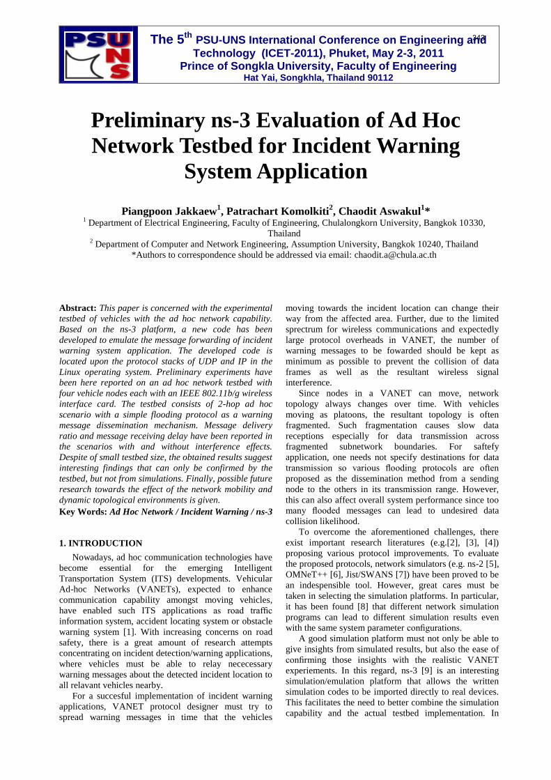
warning node and the forwarding nodes. Fig. 1 depicts a
simple timing diagram of incident warning protocol with
an incident warning node V0 and forwarding nodes V1-
V2. Nodes V0 and V2 are in the wireless coverage area
of V1, but V0 and V2 are not in the coverage area of
each other. All nodes in our first testbed here are non-
moving. Node V0 must try to forward the incident
warning message to V1-V2.
<>
Fig. 1. Timing diagram of incident warning protocol with
one incident.
In Fig. 1, starting at time t = 0 when the incident has
been detected, V0 floods a warning message to all
neighbor nodes within its transmission range
periodically, say every 0.05-0.5 seconds according to the
European ITS Communication Architecture [11]. Using
these periodic values, nodes in incident warning
application can prepare themselves while moving
towards the location of the detected incident [11]. Each
warning message has a unique message ID being
assigned by the incident warning node V0. When
forwarding nodes V1-V2 receive a warning message,
they check the message ID. To prevent the overhead
explosion of message flooding ([1], [12]), each
forwarding node sends the received message further only
when that message has been received by the node for the
first time, i.e., the ID of message is not redundant to the
IDs of previously received messages.
<>
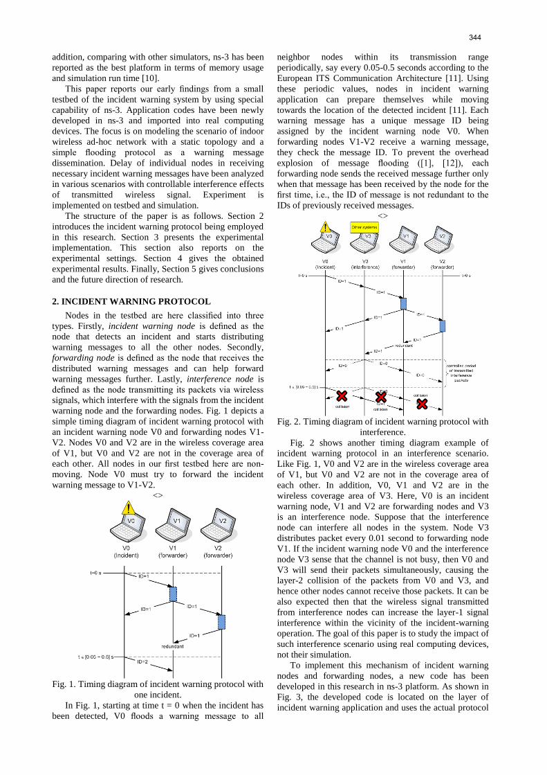
Fig. 2. Timing diagram of incident warning protocol with
interference.
Fig. 2 shows another timing diagram example of
incident warning protocol in an interference scenario.
Like Fig. 1, V0 and V2 are in the wireless coverage area
of V1, but V0 and V2 are not in the coverage area of
each other. In addition, V0, V1 and V2 are in the
wireless coverage area of V3. Here, V0 is an incident
warning node, V1 and V2 are forwarding nodes and V3
is an interference node. Suppose that the interference
node can interfere all nodes in the system. Node V3
distributes packet every 0.01 second to forwarding node
V1. If the incident warning node V0 and the interference
node V3 sense that the channel is not busy, then V0 and
V3 will send their packets simultaneously, causing the
layer-2 collision of the packets from V0 and V3, and
hence other nodes cannot receive those packets. It can be
also expected then that the wireless signal transmitted
from interference nodes can increase the layer-1 signal
interference within the vicinity of the incident-warning
operation. The goal of this paper is to study the impact of
such interference scenario using real computing devices,
not their simulation.
To implement this mechanism of incident warning
nodes and forwarding nodes, a new code has been
developed in this research in ns-3 platform. As shown in
Fig. 3, the developed code is located on the layer of
incident warning application and uses the actual protocol
344
stacks of UDP and IP in the Linux operating system.
This architecture of ns-3 platform can be implemented in
emulating mode and also be readily extensible for the
real implementation of the incident warning protocol by
replacing the simulated part with the actual network
interface on real devices. In this paper, incident warning
system is implemented in real devices.
<>
Fig. 3. Implemented protocol stacks of incident warning
system.
3. EXPERIMENTAL IMPLEMENTATION
To study the impacts of interference scenarios, the
developed small testbed of incident warning application
consists of four notebook computers to form a static
network testbed. The specification of all notebook
computers is summarized in Table 1. The operating
system is the Linux Ubuntu 9.10. The wireless network
cards are of 2 dBi gain, 16±1 dBm with wireless signals
transmission and -80 dBm receiver sensitivity. All
experiments have been conducted on channel 1 of 802.11
b/g, with the central channel frequency at 2.412 GHz.
There are two background or interference traffics we
could not eliminate: the control traffic and the other
wireless access points within the experimental area. The
control traffic is due to the ssh program, which is used to
remotely control all nodes in the system.
<>
Table 1. Computing node specification
The experimental parameters are shown in Table 2.
The main goal of the experiment is to compare network
performance parameters at interference scenario and
non-interference scenario. Incident warning messages
and interference packets have the same packet size, 1024
bytes. Testbed environment is static in its topology and
located in about 30-meter long and 15-meter wide area
on the rooftop of our 20-floor building. This location has
been chosen so as to minimize the chance of being
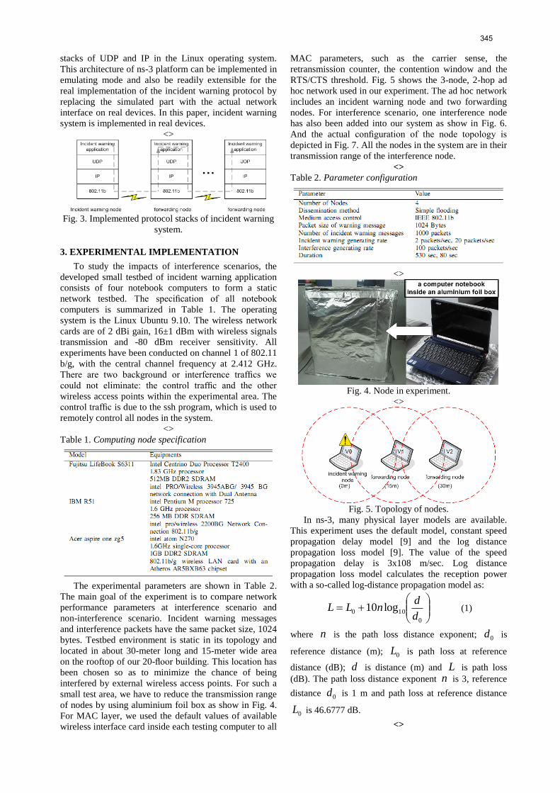
interfered by external wireless access points. For such a
small test area, we have to reduce the transmission range
of nodes by using aluminium foil box as show in Fig. 4.
For MAC layer, we used the default values of available
wireless interface card inside each testing computer to all
MAC parameters, such as the carrier sense, the
retransmission counter, the contention window and the
RTS/CTS threshold. Fig. 5 shows the 3-node, 2-hop ad
hoc network used in our experiment. The ad hoc network
includes an incident warning node and two forwarding
nodes. For interference scenario, one interference node
has also been added into our system as show in Fig. 6.
And the actual configuration of the node topology is
depicted in Fig. 7. All the nodes in the system are in their
transmission range of the interference node.
<>
Table 2. Parameter configuration
<>
Fig. 4. Node in experiment.
<>
Fig. 5. Topology of nodes.
In ns-3, many physical layer models are available.
This experiment uses the default model, constant speed
propagation delay model [9] and the log distance
propagation loss model [9]. The value of the speed
propagation delay is 3x10⁸ m/sec. Log distance
propagation loss model calculates the reception power
with a so-called log-distance propagation model as:
0
100 log10d
dnLL (1)
where n is the path loss distance exponent; 0d is
reference distance (m); 0L is path loss at reference
distance (dB); d is distance (m) and L is path loss
(dB). The path loss distance exponent n is 3, reference
distance 0d is 1 m and path loss at reference distance
0L is 46.6777 dB.
<>
345

Fig. 6. Topology of nodes with interferences.
<>
Fig. 7. Actual configuration of testbed topology on the
rooftop.
4. EXPERIMENTAL AND SIMULATION
RESULTS
The goal of the experiment is to study the VANET
system in the actual network environment with real
wireless signals being transmitted and hence subject to
possible interferences. Two network performance
metrics have been used. Firstly, the message receiving
delay is measured at the incident warning application
layer of protocol stack from the incidence warning node
to all the forwarding nodes. Secondly, the message
delivery success ratio is measured from the number of
non-redundantly received messages at forwarding nodes
over the total number of messages sent by the incident
warning node. The experiment compares the results of
testbed and simulaiton in details, as depicted in Tables 3-
8.
The main conjecture of the test is, as the interference
node injects more messages to the system, it should
induce more collisions and backoffs. The results confirm
the conjecture that both the message receiving delay and
and message delivery success ratio are degraded by
interference. However, the impact varies with scenarios.
Particularly, when comparing between similar settings of
simulations and testbed experiments, the results from
simulations are always superior. For instance, the
message receiving delay with interference in Tables 3
shows that, with the more frequent incident generating
rate, the delay is higher. This is due to higher traffic load
in the system, causing longer delay. On the other hand,
when observing the results of testbed experiments from
Tables 4 in the similar settings, the absolute values of the
delay is much higher. Nevertheless, there are virtually no
difference of delay for different incident generating rate.
In terms of the message delivery success ratio, the results
from simulations, shown in Tables 5 and 7, are 100%
when there are no interference. However, as shown in
Tables 6 and 8, in a real environment of testbed using the
2.4 GHz ISM band, the results vary greatly. Also, the
message delivery success ratio of the interference
scenario in Tables 6 and 8 show significant drops with
the more frequent incident generating rate. While both
values of the incident generating rate used in this work
are within the suggested range by the standard [11], the
resultant message delivery success ratio at the more
frequent incident generating rate may not be acceptable.
This finding strengthens the importance of testbed
implementation, as many imperfections in real
environment can not be modeled in simulations.
<>
Table 3. Simulation: message receiving delay
<>
Table 4. Testbed: message receiving delay
<>
Table 5. Simulation: message deliviery success ratio of
node V1 (%)
<>
346

Table 6. Testbed: message deliviery success ratio of node
V1 (%)
<>
Table 7. Simulation: message deliviery success ratio of
node V2 (%)
<>
Table 8. Testbed: message deliviery success ratio of node
V2 (%)
5. CONCLUSION
This paper reports our early findings from a small
testbed of the incident warning system by using special
emulation and simulation capability of ns-3 platform.
Application codes have been newly developed in ns-3
and ported into real computing devices. The focus is on
modeling the scenario of indoor wireless ad-hoc network
with a static topology and a simple flooding protocol as
warning message dissemination. Based on the obtained
values of message delivery ratio and message receiving
delay from both of the testbed and simulation
experiments, interference causes increased message
receiving delay and decreased message delivery success
ratio. This is because of traffic interference. However, for
the same experiment settings of the testbed and
simulations, simulations may not give the actual realistic
values. It should be noted that, the simulation
performances are always better than the testbed
performance. For the message receiving delay of
interference scenario with different incident warning
message generating rate, the testbed does not get the
different message receiving delay. But the higher
message delivery success ratio is achieved at the incident
generating rate of 0.5 seconds per message. It can be
concluded that, proper incident warning message
generating rate is critical to a good performance.
Therefore, despite of small testbed size, the obtained
results suggest interesting findings that can only be
confirmed by the testbed, but not from simulations. In the
future, our ongoing research will focus on the study of
the network mobility and dynamic topological
environments in the onroad real-vehicle testbed
environment.
6. REFERENCES
[1] T. L. Willke, P. Tientrakool, and N. F. Maxemchuk. A
Survey of Inter-Vehicle Communication Protocols and Their
Applications. IEEE Communiocation Surveys and Tutorials,
vol. 11, no. 2, pages 3–20, 2009.
[2] F. Hrizi, and F. Filali. Achieving Broadcasting Efficiency in
V2X Networks with a Distance-based Protocol. ComNet 2009,
pages 1–8, 2009.
[3] S. Khakbaz, and M. Fathy. A Reliability Broadcast Method
for Vehicular Ad hoc Networks Considering Fragmentation and
Intersection Problems. The Second International Conference on
Next Generation Mobile Applications, Services, and
Technologies, pages 379–384, 2008.
[4] Y. Qiangyuan, and G. Heijenk. Abiding Geocast for
Warning Message Dissemination in Vehicular Ad Hoc
Networks. ICC Workshops’08, pages 400–404, 2008.
[5] The network simulator ns-2. http://www.isi.edu/nsnam/ns/.
[6] OMNET++ Community Site. http://www.omnetpp.org/.
[7] JiST – Java in Simulation Time / SWANS – Scalable
Wireless Ad hoc Network Simulator.
http://www.jist.ece.cornell.edu/.
[8] D. Cavin, Y. Sasson, and A. Schiper. On the Accuracy of
MANET Simulators. In Proceedings of the second ACM
international workshop on Principles of mobile computing,
POMC’02, pages 38-43, 2002.
[9] ns-3. Available: www.nsnam.
[10] E. Weingartner, H. Lehn, and K. Wehrle. A performance
comparison of recent simulators. IEEE ICC, 2009.
[11] R. Bossom, R. Brignolo, T. Ernst, K. Evenson, A.
Frotscher, W. Hofs, J. Jaaskelainen, Z. Jeftic, P. Kompfner, T.
Kosch, I. Kulp, A. Kung, A. K. Mokaddem, A. Schalk, E.
Uhlemann, and C. Wewetzer. D31 European ITS
Communication Architecture. Information Society
TechnologiesCommunication for e–Safety, 2009.
[12] P. Muhlethaler, A. Laouiti, and Y. Toor. Comparison of
Flooding Techniques for Safety Applications in VANETs.
ITST ’07 7th International
Conference on ITS, 6–8, 2007.
347