preliminary engineering report chapters 1 to...
TRANSCRIPT

SILVERTOWN TUNNEL
SUPPORTING TECHNICAL DOCUMENTATION
PRELIMINARY ENGINEERING REPORT
October 2015
This report explains the proposed design of the Scheme
from an engineering perspective and sets out the
assumed method of construction.

This report forms part of a suite of documents that support the statutory public consultation for Silvertown Tunnel in October – November 2015. This document should be read in
conjunction with other documents in the suite that provide evidential inputs and/or rely on outputs or findings.
The suite of documents with brief descriptions is listed below:-
Preliminary Case for the Scheme
o Preliminary Monitoring and Mitigation Strategy
Preliminary Charging Report
Preliminary Transport Assessment
Preliminary Design and Access Statement
Preliminary Engineering Report
Preliminary Maps, Plans and Drawings
Preliminary Environmental Information Report (PEIR)
o Preliminary Non Technical Summary
o Preliminary Code of Construction Practice
o Preliminary Site Waste Management Plan
o Preliminary Energy Statement
Preliminary Sustainability Statement
Preliminary Equality Impact Assessment
Preliminary Health Impact Assessment
Preliminary Outline Business Case
o Preliminary Distributional Impacts Appraisal
o Preliminary Social Impacts Appraisal
o Preliminary Economic Assessment Report
o Preliminary Regeneration and Development Impact Assessment

Preliminary Engineering ReportOctober 2015

This page is intentionally blank

Silvertown Tunnel
Preliminary Engineering Report
Silvertown Tunnel
Preliminary Engineering Report
Planning Act 2008
Infrastructure Planning
The Infrastructure Planning (Applications: Prescribed Forms and Procedure) Regulations 2009
Document Reference: ST150030-PLN-ZZZ-ZZ-RP-PC-0005
Author: Transport for London
Rev. Date Approved By Signature Description
1 02/10/2015 David Rowe (TfL Lead Sponsor) For Consultation
Richard De Cani (TfL MD Planning)

This page is intentionally blank

00Contents
AbbreviationsGlossarySummary 1 Introduction
1.1 Purpose of this report
1.2 Scheme description
1.3 Site description
1.4 Structure of this report
1.5 Future design and build development
1.6 Next steps
2 Scheme Constraints 2.1 Alignment obstructions
2.2 Design standards and principles
2.3 Planned infrastructure and planned developments
2.4 Limits of deviation & limit of land to be acquired or used
3 Scheme Development - Consultation & Stakeholder Engagement 3.1 Development of the Reference Design
4 Reference Design Proposals4.1 General
4.2 Highways
4.3 Bridges and retaining walls
4.4 Tunnels
4.5 Tunnel safety systems
4.6 Tunnel service buildings and plant rooms
4.7 Utilities
5 Construction Methodology 5.1 Introduction
5.2 Overall approach
5.3 Programme
5.4 Construction compounds
5.5 Surface works – Silvertown
5.6 Surface works - Greenwich
5.7 Bored tunnel works
5.8 Cut and cover tunnel works
5.9 Testing and commissioning
5.10 Demobilisation
Appendix A: Preliminary Maps, Plan and Drawings

Abbreviations
ALARP As Low As Reasonably PracticableCCTV Closed Circuit TelevisionCDM Construction Design and Management Regulations (2015)DBFM Design Build Finance and MaintainDCO Development Consent OrderDfT Department for TransportDLR Docklands Light RailwayEAL Emirates Air LineEU European UnionFFFS Fixed Fire Fighting SystemHFS High Friction SurfaceHGV Heavy Goods VehicleHSE Health and Safety ExecutiveHV High VoltageLLAU Limit of Land to be Aquired or UsedLoD Limits of DeviationLSTOC London Streets Tunnels Operations CentreLTVS Longitudinal Tunnel Ventilation SystemLU London UndergroundLV Low VoltageM&E Mechanical & ElectricalMTS Mayor’s Transport StrategyNJUG National Joint Utilities GroupNMU Non-Motorised UsersPAVA Public Address Voice AlarmPEIR Preliminary Environmental Information ReportPER Preliminary Engineering ReportPEVS Portal Extract Ventilation SystemRSA Road Safety AuditRUC Road User ChargingSSD Stopping Sight DistanceSuDS Sustainable Drainage SystemsTBM Tunnel Boring MachineTDSCG Tunnel Design and Safety Consultation GroupTfL Transport for LondonUK United KingdomUTC Urban Traffic ControlVMS Variable Message Signs

Glossary
Term Explanation Blackwall Tunnel A road tunnel underneath the River Thames in east London, linking the London Borough of Tower Hamlets with the Royal Borough of Greenwich,
comprising two bores each with two lanes of traffic. The tunnel was originally opened as a single bore in 1897, as a major transport project to improve commerce and trade in London’s east end. By the 1930s, capacity was becoming inadequate, and consequently, a second bore opened in 1967, handling southbound traffic while the earlier 19th century tunnel handled northbound.
Bus Gate Bus gates are traffic signals often provided within bus priority schemes to assist buses and other permitted traffic when leaving a bus lane to enter or cross the general flow of traffic or to meter the flow of general traffic as it enters the road link downstream of the bus lane. Depending on their purpose, bus gates can be located remote from other signals or they can be positioned immediately upstream of a signal controlled junction, as a bus pre-signal.
CDM (2015) The Construction (Design and Management) Regulations 2015 set out the roles and responsibilities of parties involved in construction projects in relation to health and safety during the project life cycle including design, construction operation and maintenance stages.
Contractor Anyone who directly employs or engages construction workers or manages construction work. Contractors include sub-contractors, any individual self-employed worker or business that carries out, manages or controls construction work.
Control Centre Facility to deal with issues with over-height, illegal and unsafe vehicles going through Blackwall and Silvertown Tunnels, and help manage traffic.Cut and Cover A method of construction for shallow tunnels where a trench is excavated and roofed over with an overhead support system strong enough to carry the
load of what is to be built above the tunnel.Design, Build, Finance and Maintain (DBFM) A DBFM company is typically a consortium of private sector companies, formed for the specific purpose of providing the services under the DBFM
contract. This is also technically known as a Special Purpose Vehicle (SPV). The DBFM Company will obtain funding to design and build the new facilities and then undertake routine maintenance and capital replacement during the contract period, which is typically 25 to 30 years. The DBFM Company will repay funders from payments received from TfL during the lifespan of the contract. Receipt of payments from TfL will depend on the ability of the DBFM Company to deliver the services in accordance with the output specified in the contract and will be subject to deductions if performance is not satisfactory.
Department for Transport (DfT) The government department responsible for the English transport network and a limited number of transport matters in Scotland, Wales and Northern Ireland that have not been devolved.
Detailed Design Design that precisely defines that works that are to be constructed to meet the specified outputs.Development Consent Order (DCO) This is a statutory order which provides consent for the project and means that a range of other consents, such as planning permission and listed
building consent, will not be required. A DCO can also include provisions authorising the compulsory acquisition of land or of interests in or rights over land which is the subject of an application. http://infrastructure.planninginspectorate.gov.uk/help/glossary-of-terms/
Docklands Light Railway (DLR) An automated light metro system serving the Docklands and east London area. The DLR is operated under concession awarded by Transport for London to KeolisAmey Docklands, a joint venture between transport operator Keolis and infrastructure specialists Amey plc.
Earth Pressure Balance (EPB) Tunnel Boring Machine
A type of tunnel boring machine used in soft ground. The machine uses the excavated material to balance the pressure at the tunnel face. Pressure is maintained in the cutter head by controlling the rate of extraction of spoil through the removal Archimedes screw and the advance rate of the machine.
Emirates Air Line (EAL) A cable car service across the River Thames in east London, linking the Greenwich peninsula to the Royal Victoria Dock. The service is managed by TfL, and is part of the TfL transport network.
Gasholder A large container in which natural gas is stored near atmospheric pressure at ambient temperatures.Greenwave Coordinated control of a series of traffic signals to allow continuous traffic flow in a given direction.Heavy Goods Vehicle (HGV) European Union term for any vehicle with a gross combination mass of over 3500kg.

London Streets Tunnels Operations Centre (LSTOC)
LSTOC operates the traffic and tunnel safety systems for various road tunnels in London operated by Transport for London. LSTOC operations are fundamental to the safe and reliable operation of TfL’s tunnels and performance of the corridors serviced by the London streets traffic control system.
Outline Design Defines the design principles and freezes the scope of the project.Priority Lane A dedicated highway lane that has restricted occupancy, available for use by buses and Heavy Goods Vehicles.Reference Design Design proposals that the consultation and DCO application will refer to.Secant Piles Piles are vertical structural elements of deep foundations. Secant pile walls are formed by constructing intersecting reinforced concrete piles. The
secant piles are reinforced with either steel rebar or with steel beams and are constructed by either drilling under mud or auguring. Primary piles are installed first with secondary piles constructed in between primary piles once the latter gain sufficient strength.
Service Building, Tunnel Service Building, Portal Building
The building housing all control, power supply, and other essential equipment for the operation of the tunnel. Also houses firefighting control and ventilation equipment. Serves as a maintenance base and has the facility to become a standby operations room.
Sheet Pile Sheet piles can be a temporary or permanent earth retention solution, providing support and reducing groundwater ingress. Steel sheets are driven into the ground, interlocking with neighbouring piles in order to create a continuous wall.
Slurry Shield (SS) Tunnel Boring Machine A type of tunnel boring machine used in soft ground with very high water pressure or where ground conditions are granular (sands and gravels) such that a plug cannot be formed in the removal Archimedes screw. The cutter head is filled with pressurised slurry which applies hydrostatic pressure to the excavation face. The slurry also acts as a transport medium by mixing with the excavated material before being pumped out of the cutter head back to a slurry separation plant.
Spoil The material excavated by the tunnel boring machine during the construction of the bored tunnel.SuDS Sustainable Drainage Systems (SuDS) are water management solutions designed to reduce the impact of surface water runoff from new and existing
developments to the natural environment. The purpose of such systems is to improve water quality and store or reuse surface runoff to reduce the discharge rate to the watercourse.
Tension Piles Piles are vertical structural elements of deep foundations. Tension piles are used to resist uplift/pull-out loads.The O2 A large entertainment district on the Greenwich peninsular, including an indoor arena, cinema, bars and restaurants. It is built largely within the former
Millennium Dome.The Scheme The construction of a new bored tunnel under the River Thames between the Greenwich peninsula and Silvertown, as well as necessary alterations to
the connecting road network and the introduction of user charging at both Silvertown and Blackwall tunnels.Toucan Crossing A signal controlled crossing that allows pedestrians and cyclists to cross a road safely.Transport for London (TfL) The local government body responsible for most aspects of the transport system in Greater London. Its role is to implement transport strategy and to
manage transport services across London. These services include: buses, the Underground network, Docklands Light Railway, Overground and Trams. TfL also runs Santander Cycles, London River Services, Victoria Coach Station and the Emirates Air Line. As well as controlling a 580km network of main roads and the city’s 6,000 traffic lights, TfL regulates London’s private hire vehicles and the Congestion Charge scheme.
The Tunnel, Silvertown Tunnel A new bored tunnel under the River Thames between the Greenwich peninsula and Silvertown.Tunnel Boring Machine (TBM) A machine used to excavate tunnels with a circular cross section. There are two main types of closed face TBMs: Earth Pressure Balance (EPB) and
Slurry Shield (SS). Please see those terms for further explanation.Ventilation Building Surface level structure of a ventilation equipment, fans and an exhaust shaft, used to move fresh air underground by drawing air from the tunnel
and venting it to the atmosphere. Located adjacent to and integral with the Tunnel Services Buildings.
Glossary

Summary
This Preliminary Engineering Report (PER) presents the proposed engineering design and an assumed method of construction for the Silvertown Tunnel scheme. The engineering design has been developed up to a Reference Design stage that defines the scheme in sufficient detail to allow consultees to understand the scope and extent of the Scheme and to inform the studies assessing the environmental, socio-economic, construction and transport related impacts of the Scheme. The Reference Design incorporates a number of changes arising from consultee feedback from earlier consultations which are described in this Report.
The Reference Design establishes:• that construction of the Scheme is feasible
and that it can be completed within thetimescale indicated;
• a possible construction sequenceallowing traffic movements and services(utilities) supplies to be maintained duringconstruction;
• the land required for the permanent works;• land required temporarily for the safe
construction of the works; and• a level of detail to allow assessment of the
likely costs, impacts, effects and benefits ofthe Scheme.
The report includes illustrative examples of what the Scheme might look like and how it could be built.
This document is part of a suite of documents which have been made available for the statutory consultation on the Silvertown Tunnel scheme which runs from 5 October to 27 November 2015. Following this consultation, Transport for London (TfL) will carefully consider comments made by the public and stakeholders in order to improve and refine the Scheme proposals. TfL aims to submit a DCO application to the Planning Inspectorate in March 2016. This application will seek the consent of the Secretary of State for Transport to build and operate the proposed tunnel and all associated measures.

This page is intentionally blank

01Introduction 1.1 Purpose of this report
1.2 Scheme description
1.3 Site description
1.4 Structure of this report
1.5 Future design and build development
1.6 Next steps

10
Silvertown Tunnel | Preliminary Engineering Report

01 Introduction
11
01Introduction
1.1 Purpose of this report
1.1.1 The purpose of this Preliminary Engineering Report (PER) is to provide a description of the engineering aspects of the Reference Design and the assumed method of construction for the Silvertown Tunnel project, referred to throughout this document as the Scheme.
1.1.2 The illustrative designs for the permanent spaces, above ground structures and access arrangements for the Scheme are described in the Design and Access Statement.
1.2 Scheme description
1.2.1 The Scheme would comprise a new dual two-lane connection between the A102 Blackwall Tunnel Approach on Greenwich Peninsula (Royal Borough of Greenwich) and the Tidal Basin Roundabout junction on the A1020 Lower Lea Crossing/Silvertown Way (London Borough of Newham) by means of twin tunnel bores under the River Thames and associated approach roads. The Silvertown Tunnel would be approximately 1.4km long and would be able to accommodate large vehicles including double-deck buses. One lane in each direction would be reserved for buses, coaches and heavy goods vehicles (HGV’s).
1.2.2 On the north side, the tunnel approach road would connect to the Tidal Basin Roundabout, which would be altered to create a new signal-controlled roundabout linking the Silvertown Way, Dock Road and the Lower Lea Crossing. Dock Road would be realigned to accommodate the new tunnel and approach road. On the south side, the A102 would be locally widened to create new slip-road links to the Silvertown Tunnel. A new flyover would be built to take southbound traffic exiting the
Blackwall Tunnel over the northbound approach to the Silvertown Tunnel. The existing Boord Street footbridge over the A102 would be replaced with a combined pedestrian and cycle bridge.
1.2.3 New Tunnel Services buildings would be located close to each portal to house the plant and equipment necessary to operate the tunnel, including ventilation equipment.
Western Gateway
Emirates Greenwich Peninsula
EmiratesRoyalDocks
EastIndia
NorthGreenwich
CanningTown
RoyalVictoria
CustomHouse
Prince Regent
Pontoon Dock
WestSilvertown
All Saints
Blackwall
Victoria Dock Rd
E India Dock Rd A13
Abbott Rd
Manchester Rd
Newham WayBarking RdA 1011
Blackwall TunnelBlackwall Tunnel
Pres
ton`
s Rd
A102
Blackwall Tunnel Approach
A12
A12
N Woolwich Rd
Royal Victoria Dock
River Thames
Silverto
wn Tunnel
Keir Hardie Recreation Ground
Thames Barrier Park
A1261
Lower Lea Crossing
Silvertown Way
1.2.4 The introduction of free-flow road user charging (RUC) on both the Blackwall and Silvertown Tunnels would play a fundamental part in managing traffic demand and would support the financing of the construction and operation of the Silvertown Tunnel. The design of the tunnel would include a dedicated bus/coach and HGV lane, which would provide opportunities for TfL to develop additional cross-river bus routes.
1.2.5 Subject to consent being granted, main construction works would be likely to commence in 2018 and would last approximately four years with the new tunnel opening in 2022/23. A Tunnel Boring Machine (TBM) would be used to bore the main tunnel sections under the river with shorter sections of cut and cover tunnel being constructed at either end linking to the portals. The proposal is to erect and launch the TBM from specially constructed chambers at Silvertown and Greenwich Peninsula. The main construction compound would be located at Silvertown to utilise Thames Wharf to facilitate the removal of spoil and delivery of materials by river. A secondary site compound would be located adjacent to the proposed tunnel approach ramps on the Greenwich Peninsula.
A1020
Figure 1.1 – Scheme overview
12
Silvertown Tunnel | Preliminary Engineering Report
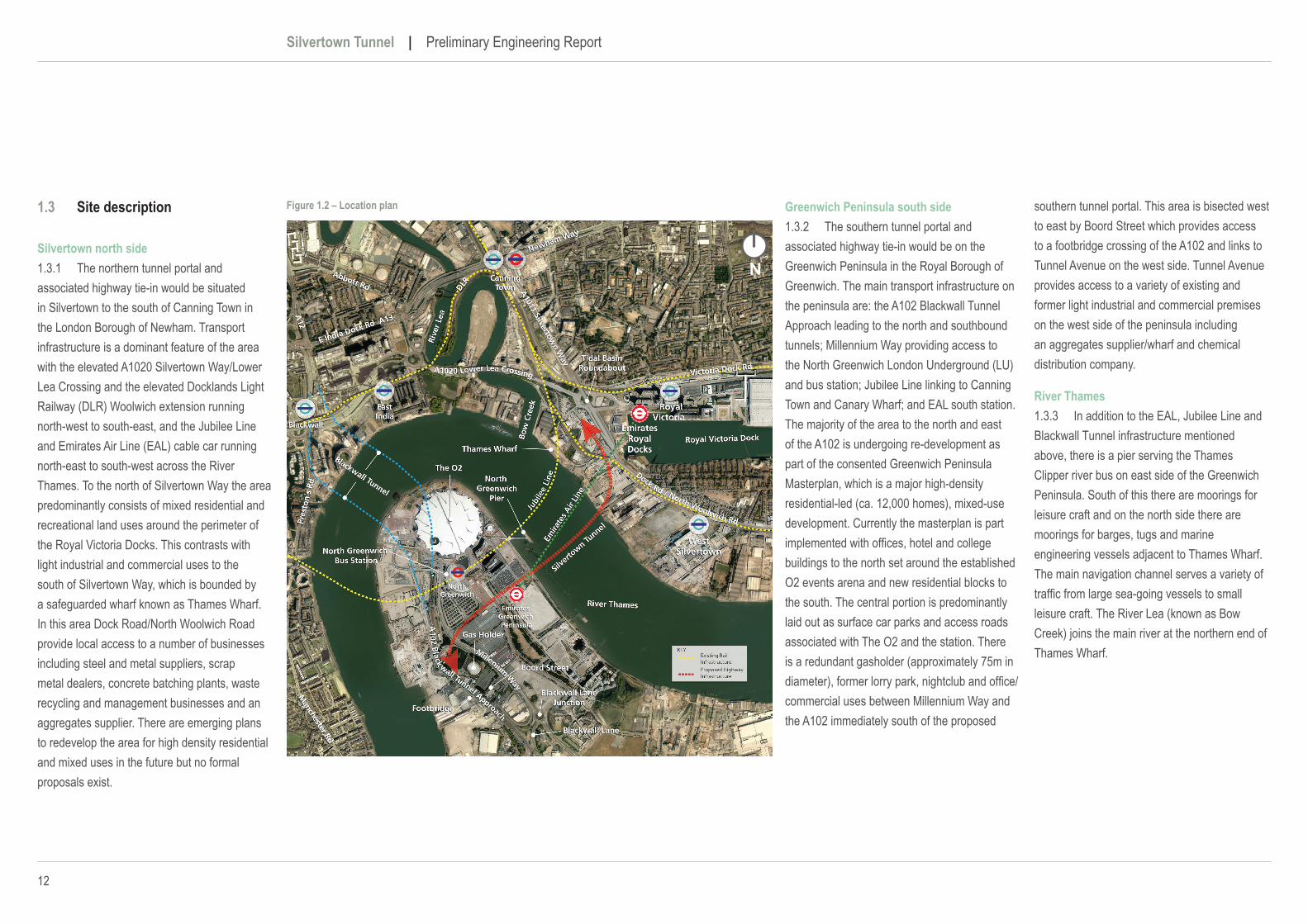
southern tunnel portal. This area is bisected west to east by Boord Street which provides access to a footbridge crossing of the A102 and links to Tunnel Avenue on the west side. Tunnel Avenue provides access to a variety of existing and former light industrial and commercial premises on the west side of the peninsula including an aggregates supplier/wharf and chemical distribution company.
River Thames1.3.3 In addition to the EAL, Jubilee Line and Blackwall Tunnel infrastructure mentioned above, there is a pier serving the Thames Clipper river bus on east side of the Greenwich Peninsula. South of this there are moorings for leisure craft and on the north side there are moorings for barges, tugs and marine engineering vessels adjacent to Thames Wharf. The main navigation channel serves a variety of traffic from large sea-going vessels to small leisure craft. The River Lea (known as Bow Creek) joins the main river at the northern end of Thames Wharf.
1.3 Site description
Silvertown north side1.3.1 The northern tunnel portal and associated highway tie-in would be situated in Silvertown to the south of Canning Town in the London Borough of Newham. Transport infrastructure is a dominant feature of the area with the elevated A1020 Silvertown Way/Lower Lea Crossing and the elevated Docklands Light Railway (DLR) Woolwich extension running north-west to south-east, and the Jubilee Line and Emirates Air Line (EAL) cable car running north-east to south-west across the River Thames. To the north of Silvertown Way the area predominantly consists of mixed residential and recreational land uses around the perimeter of the Royal Victoria Docks. This contrasts with light industrial and commercial uses to the south of Silvertown Way, which is bounded by a safeguarded wharf known as Thames Wharf. In this area Dock Road/North Woolwich Road provide local access to a number of businesses including steel and metal suppliers, scrap metal dealers, concrete batching plants, waste recycling and management businesses and an aggregates supplier. There are emerging plans to redevelop the area for high density residential and mixed uses in the future but no formal proposals exist.
Greenwich Peninsula south side1.3.2 The southern tunnel portal and associated highway tie-in would be on the Greenwich Peninsula in the Royal Borough of Greenwich. The main transport infrastructure on the peninsula are: the A102 Blackwall Tunnel Approach leading to the north and southbound tunnels; Millennium Way providing access to the North Greenwich London Underground (LU) and bus station; Jubilee Line linking to Canning Town and Canary Wharf; and EAL south station. The majority of the area to the north and east of the A102 is undergoing re-development as part of the consented Greenwich Peninsula Masterplan, which is a major high-density residential-led (ca. 12,000 homes), mixed-use development. Currently the masterplan is part implemented with offices, hotel and college buildings to the north set around the established O2 events arena and new residential blocks to the south. The central portion is predominantly laid out as surface car parks and access roads associated with The O2 and the station. There is a redundant gasholder (approximately 75m in diameter), former lorry park, nightclub and office/commercial uses between Millennium Way and the A102 immediately south of the proposed
Figure 1.2 – Location plan
01 Introduction
13
1.4 Structure of this report
1.4.1 This report details the main Reference Design and construction aspects of the project and further describes the main Scheme elements.
1.4.2 This report is set out as follows:• Chapter 2 Scheme Constraints;• Chapter 3 Scheme Development –
Consultation & Stakeholder Engagement;• Chapter 4 Reference Design Proposals;• Chapter 5 Construction Methodology;• Appendix A Preliminary Maps, Plans and
Drawings.
1.4.3 This report should be read in conjunction with Preliminary Maps, Plans and Drawings that can be found in Appendix A.
1.5 Future design and build development
1.5.1 As noted in the Outline Business Case, TfL propose to deliver the Silvertown Tunnel through a private finance initiative and has established that a Design Build Finance and Maintain (DBFM) contract arrangement would best meet the project objectives and constraints, and achieve an appropriate risk balance. A DBFM contract would be competitively tendered in accordance with EU procurement procedures.
1.5.2 The DBFM contractor would complete the Detailed Design, construct the tunnel and supporting infrastructure and be responsible for maintenance during an anticipated 30 year concession period. TfL would control the day to day operation (traffic management) of the Silvertown Tunnel while Blackwall Tunnel would continue to be managed by TfL under the existing operations and maintenance arrangements.
1.5.3 The engineering design for the Scheme has been developed in sufficient detail to enable a Development Consent Order (DCO) application to be submitted. Termed the Reference Design,
it defines the Scheme in sufficient detail to allow stakeholders to understand the scope and extent of the scheme and to inform the studies assessing the environmental, socio-economic, construction and transport related impacts of the Scheme. In preparation for the Statutory Consultation the Reference Design has been reviewed to take into consideration stakeholder requirements identified during earlier consultations.
1.5.4 The Reference Design and associated construction methodology and programme has established:• that construction of the Scheme is feasible
and can be completed within the timescale indicated;
• a possible construction sequence allowing traffic movements and services (utilities) supplies to be maintained during construction;
• the land required for the permanent works;• land required temporarily for the safe
construction of the works; and• a level of detail to allow assessment of the
likely costs, impacts, effects and benefits of the Scheme.
1.5.5 The Reference Design includes illustrative examples of what a suitable solution might look like and how it could be built.
1.5.6 As part of the Scheme procurement process, bidders for the DBFM contract would submit proposals to meet TfL’s specification and requirements including any requirements arising through the DCO process. Bidders’ proposals would be subject to a robust technical and environmental evaluation in addition to financial evaluation to ensure a sympathetic enhancement of highway infrastructure is delivered to meet the Scheme objectives whilst also offering value for money.
1.5.7 Subject to award of the DCO a DBFM contractor would be appointed who would be responsible for completing the Detailed Design and for undertaking the Scheme construction. TfL’s specifications together with the requirements and commitments arising from the DCO examination would be incorporated in the contract documents and the contractor’s detailed proposals would be subject to further comprehensive review prior to construction to ensure that the final design and construction methodologies have no impacts more adverse than than those assessed for the DCO.
1.6 Next steps
1.6.1 This Preliminary Engineering Report is part of a suite of documents which have been made available for the statutory consultation on the Silvertown Tunnel scheme which runs from 5 October to 27 November 2015. Following this consultation, TfL will carefully consider comments made by the public and stakeholders in order to improve and refine the Scheme proposals. TfL aims to submit a DCO application to the Planning Inspectorate in March 2016. This application will seek the consent of the Secretary of State for Transport to build and operate the proposed tunnel and all associated measures.

This page is intentionally blank

02Scheme Constraints2.1 Alignment obstructions
2.2 Design standards and principles
2.3 Planned infrastructure and planned developments
2.4 Limits of deviation & limit of land to be acquired or used

16
Silvertown Tunnel | Preliminary Engineering Report

02 Scheme Constraints
17
DLR Viaductspan and piers
Old dockentrance
A1020 Lower Lea Crossing
Manchester Rd
E India Dock Rd A13
Abbott Rd
Newham Way
Blackwall Tunnel
A12
Royal Victoria Dock
River Thames
The O2
Rive
r Le
a
Jubi
lee
Line
Tidal BasinRoundabout
DLR
Gasometer
Emira
tes
Air
Line
Southtie-in
EAL southtower
River Wall
EAL northintermediate
tower
EAL northintermediate
tower
Northtie-in
A102 B
lack
wall Tunnel Approach
02 Scheme Constraints
2.1 Alignment obstructions
2.1.1 Urban highway tunnels, especially under rivers, are particularly complex due to the requirement to tie the new infrastructure into suitable points on the existing highway network. The design and construction of tunnels in urban areas presents challenges with regards to finding suitable space for new assets, navigating between obstructions of existing built infrastructure, committed developments and the local topography.
2.1.2 There are a number of existing physical constraints on the horizontal and vertical alignment of the proposed tunnel which are shown on Figure 2.1 and detailed further below.
River Thames2.1.3 The river bed profile and flood defence walls constitute constraints on the vertical alignment for a bored tunnel where suitable depth of cover must be maintained and sub-surface obstructions avoided. The river walls are generally constructed from sheet piles or from masonry blocks founded below river bed level. Prior to the start of tunnelling the river walls would be subject to a condition survey. Any works required to ensure the stability of the wall structures would be carried out in advance of the tunnel construction work in their vicinity.
Royal Victoria Dock entrance and outfall drain2.1.4 At the northern end of the Scheme, the proposed highway passes close to the Royal Victoria Dock. Historically there was an operational lock at the western end of the Royal Victoria Dock. This was filled in during the 1950s to recover land for development. The material used to fill in the dock entrance is not fully known but is understood to have been a mixture of building waste including brick, wood and steel. To reduce the risk associated with constructing the bored tunnel through ground conditions that are uncertain, the tunnel launch chamber could be located to the south of this obstruction.
Figure 2.1 – Scheme constraints plan
South BankRiver Wall
Clearance from tunnelto river wall approx 4.0m
Clearance from tunnelto river wall approx 5.0m
Clearance from tunnelto river bed approx 6.5m
North BankRiver Wall
Proposed Tunnel
Figure 2.2 – Scheme constraints profile
18
Silvertown Tunnel | Preliminary Engineering Report
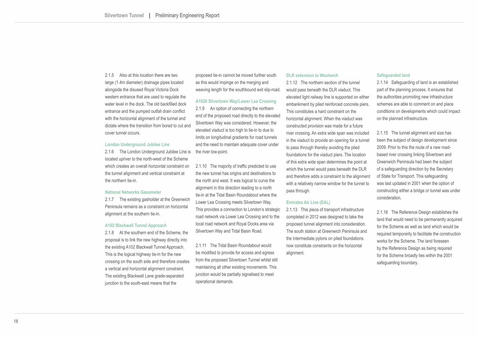
2.1.5 Also at this location there are two large (1.4m diameter) drainage pipes located alongside the disused Royal Victoria Dock western entrance that are used to regulate the water level in the dock. The old backfilled dock entrance and the pumped outfall drain conflict with the horizontal alignment of the tunnel and dictate where the transition from bored to cut and cover tunnel occurs.
London Underground Jubilee Line2.1.6 The London Underground Jubilee Line is located upriver to the north-west of the Scheme which creates an overall horizontal constraint on the tunnel alignment and vertical constraint at the northern tie-in.
National Networks Gasometer2.1.7 The existing gasholder at the Greenwich Peninsula remains as a constraint on horizontal alignment at the southern tie-in.
A102 Blackwall Tunnel Approach2.1.8 At the southern end of the Scheme, the proposal is to link the new highway directly into the existing A102 Blackwall Tunnel Approach. This is the logical highway tie-in for the new crossing on the south side and therefore creates a vertical and horizontal alignment constraint. The existing Blackwall Lane grade-separated junction to the south-east means that the
proposed tie-in cannot be moved further south as this would impinge on the merging and weaving length for the southbound exit slip-road.
A1020 Silvertown Way/Lower Lea Crossing2.1.9 An option of connecting the northern end of the proposed road directly to the elevated Silvertown Way was considered. However, the elevated viaduct is too high to tie-in to due to limits on longitudinal gradients for road tunnels and the need to maintain adequate cover under the river low-point.
2.1.10 The majority of traffic predicted to use the new tunnel has origins and destinations to the north and west. It was logical to curve the alignment in this direction leading to a north tie-in at the Tidal Basin Roundabout where the Lower Lea Crossing meets Silvertown Way. This provides a connection to London’s strategic road network via Lower Lea Crossing and to the local road network and Royal Docks area via Silvertown Way and Tidal Basin Road.
2.1.11 The Tidal Basin Roundabout would be modified to provide for access and egress from the proposed Silvertown Tunnel whilst still maintaining all other existing movements. This junction would be partially signalised to meet operational demands.
DLR extension to Woolwich 2.1.12 The northern section of the tunnel would pass beneath the DLR viaduct. This elevated light railway line is supported on either embankment by piled reinforced concrete piers. This constitutes a hard constraint on the horizontal alignment. When the viaduct was constructed provision was made for a future river crossing. An extra wide span was included in the viaduct to provide an opening for a tunnel to pass through thereby avoiding the piled foundations for the viaduct piers. The location of this extra wide span determines the point at which the tunnel would pass beneath the DLR and therefore adds a constraint to the alignment with a relatively narrow window for the tunnel to pass through.
Emirates Air Line (EAL)2.1.13 This piece of transport infrastructure completed in 2012 was designed to take the proposed tunnel alignment into consideration. The south station at Greenwich Peninsula and the intermediate pylons on piled foundations now constitute constraints on the horizontal alignment.
Safeguarded land2.1.14 Safeguarding of land is an established part of the planning process. It ensures that the authorities promoting new infrastructure schemes are able to comment on and place conditions on developments which could impact on the planned infrastructure.
2.1.15 The tunnel alignment and size has been the subject of design development since 2009. Prior to this the route of a new road-based river crossing linking Silvertown and Greenwich Peninsula had been the subject of a safeguarding direction by the Secretary of State for Transport. This safeguarding was last updated in 2001 when the option of constructing either a bridge or tunnel was under consideration.
2.1.16 The Reference Design establishes the land that would need to be permanently acquired for the Scheme as well as land which would be required temporarily to facilitate the construction works for the Scheme. The land foreseen by the Reference Design as being required for the Scheme broadly lies within the 2001 safeguarding boundary.

02 Scheme Constraints
19
2.2 Design standards and principles
2.2.1 The Reference Design proposals have been developed adopting the Design Manual for Roads and Bridges (DMRB). This document provides a comprehensive manual system which incorporates current Standards, Advice Notes and other published documents relating to Trunk Road Works. The documents in the DMRB have been issued by the Department for Transport (DfT) specifically for Trunk Road Works throughout the UK.
2.2.2 The DMRB sets a standard of good practice that provides requirements, advice and guidance resulting from research, practical experience and legislative requirements. It has been adopted by TfL for the London road network and is the benchmark for the majority of TfL highway works including the Scheme. TfL has also used other advice published by the DfT together with its own guidance, such as TfL’s Streetscape Guidance, to inform the Scheme design.
2.2.3 Consideration for safety in the Reference Design development has been paramount with Construction (Design and Management) Regulations 2015 (CDM) principles applied including the elimination, reduction and control of risks through the design process. An independent Road Safety Audit
(RSA) has also been undertaken in accordance with the appropriate standards to evaluate the Scheme proposals and identify any potential concerns with mitigations measures incorporated in the Reference Design proposals.
2.2.4 The Reference Design has also adopted a set of design principles as discussed in the Design and Access Statement.
2.3 Planned infrastructure and planned developments
2.3.1 There are plans for significant regeneration either side of the River Thames along the route of the Scheme. These plans act as constraints to some aspects of the Scheme.
2.3.2 A consented masterplan for the development of the Greenwich Peninsula has been in place since 2004 and has been partly implemented. Over the past 2 years, under the new direction of lead developer Knight Dragon, an updated masterplan has been developed revised proposals were submitted for planning permission in April 2015 and the Royal Borough of Greenwich has resolved to grant permission subject to confirmation by the Mayor of London. In light of this planning status the current Silvertown Tunnel scheme proposals have been based on the previously consented Masterplan dated 2004, which was designed to accommodate the proposed new crossing
alignment. This revised application introduces further constraints on the Scheme proposals. Transport for London (TfL) and the developers for the Greenwich Peninsula are working closely to resolve structural interfaces and coordinate construction phasing.
2.3.3 There are as yet no consented developments in the Silvertown area within the immediate vicinity of the Scheme. Details of developments within the wider area are provided within the Preliminary Design and Access Statement. Nevertheless, in line with the objectives for the Scheme, the Reference Design ensures that the area around the Scheme could be developed at some stage in the future, in line with the aspirations of the Greater London Authority (GLA) and the London Borough of Newham.
2.4 Limits of deviation & limits of land to be acquired or used
2.4.1 The alignment of the Reference Design is subject to limits of deviation. The limits of deviation (LoD) define the maximum extent to which the location of the main elements of the Scheme, such as the tunnel bores, can deviate both horizontally (in plan) and vertically (in elevation). The Reference Design is a preliminary design only and therefore the LoD provide the necessary flexibility to allow for small adjustments once the detailed design has been
prepared. It is standard practice for such limits to be included in DCO applications and these will be shown on the works plans which accompany the DCO application.
2.4.2 In addition, the DCO will provide a power to carry out other works known as ancillary works, such as the provision of environmental mitigation. These ancillary works must be carried out within the limits of land to be acquired or used.
2.4.3 Taking the LoD into consideration in combination with the assumed construction methodology this has enabled the limits of land to be acquired or used (LLAU) to be determined for the Scheme. This ensures that the Scheme proposals have identified sufficient permanent and temporary land requirements for the safe construction, operation and maintenance activities that are sensitive to the existing land uses and planned developments.
2.4.4 The LLAU are as shown on the Preliminary Maps, Plans and Drawings in Appendix A.
2.4.5 The above physical constraints, design standards and principles, planned developments and land requirements have combined to shape the proposed horizontal and vertical alignment for the Scheme.

This page is intentionally blank
03Scheme Development -Consultation & Stakeholder Engagement 3.1 Development of the Reference Design

22
Silvertown Tunnel | Preliminary Engineering Report

03 Scheme Development - Consultation & Stakeholder Engagement
23
03Scheme Development - Consultation & Stakeholder Engagement
3.1 Development of the Reference Design
3.1.1 Since the selection of the preferred tunnel option in early 2014 the Scheme proposals have undergone development and improvement, mainly as a result of detailed public consultation and engagement with key stakeholders including:
• host boroughs and other local authorities;• statutory bodies and undertakers
(e.g. Port of London Authority, EnvironmentAgency, Utilities);
• Emergency Services;• those with land interests (e.g. owners,
developers and tenants).
3.1.2 A number of design and construction related changes have been adopted within the Reference Design as a direct result of this engagement activity. These are summarised in Table 3.1.
3.1.3 Furtherschemerefinementsmaybeincorporated following the Statutory Consultation. TfL will carefully consider comments made by the public and stakeholders in order to improve and refine the Scheme proposals. A summary of the 2015 consultation process will be reported separately as part of the documentation supporting the DCO application.

24
Silvertown Tunnel | Preliminary Engineering Report
Design Development Reason for Development Impacts and BenefitsModificationoftheproposedconstructionmethodology and sequence to include a temporary diversion of Millennium Way during construction of the tunnel.
The change has been implemented in response to requests from existing service providers, operators and businesses.
This development will maintain full access along Millennium Way for the full duration of the construction period which will improve access during the works for existing service providers, operators and businesses. The development also reduces the proposed footprint of the works adjacent to existing operations.
Modificationoftheconstructionmethodologyand sequence to co-ordinate with the consented Greenwich Master Plan
Alignment with the construction planning for the consented Master Plan The revised construction strategy will minimise the disruption to existing service providers and venues arising from the combined impacts of the Silvertown Tunnel Works and the construction works associated with the consented development plans for the Greenwich peninsula.
Development of the design for the proposed Boord Street cycle and pedestrian crossing to create a more compact structure
Feedbackfromstakeholderswhichidentifiedthatthepreviousproposalsimpactedonaccesses to existing services and businesses
In comparison to the earlier proposals this development improves the proposed accesses for existing businesses and services. It retains existing planting along highway boundary and reduces the footprint of the land required for this element of the scheme.
Development of the layout of the Tidal Basin Roundabout
Feedback from stakeholders and existing service providers relating to the extent of land occupied by the junction and the constraints that the junction layout placed on current land use and future land use opportunities. Feedback from the Stage 1 Road Safety Audit team.
The design developments achieve a simpler arrangement through creating a more open layout and through removing one dedicated entry lane onto the roundabout. The changes reduce the overall area of carriageway at the junction and address a number of operational concerns raised in the Stage 1 Road Safety Audit. These changes contribute to a reduction in the number of constraints to current and future land use around the area that were inherent in the previous arrangement.
Introduction of low noise road surfacing on Tidal Basin Road between Tidal Basin Roundabout and Silvertown Way
Reductioninimpactarisingfromchangedtrafficlevelsontrafficnoiselevels The proposal to provide low noise surfacing to the link between Tidal Basin Roundabout and Silvertown Way mitigatestheimpactofchangedtrafficlevelsonthislinkarisingfromthenewSilvertowntunnel.
ModificationstothesitingandlayoutoftheVentilation Building and Tunnel Service Buildings at the Service Compound adjacent to the North Portal
Feedback from stakeholders which proposed that the tunnel service compound could be located on land more suitable for this type of land use.
These changes contribute to a reduction in the constraints to current and future land use around the area that were inherent in the previous arrangement. The new arrangement also creates a more open aspect on the land adjacent to the realigned Dock Road.
Rationalisation of the proposals for the construction and operation of temporary loading facilities in the River Thames at the Silvertown Works Compound.
Feedback from stakeholders relating to encouraging greater use of the river for construction logistics and to mitigation of environmental impacts. Requests from existing businesses and service providers to minimise impacts to their operations during the construction period.
The design has developed to focus on a single option of using the existing wharves directly onto the River Thames. This reduces the potential impact on existing operators. The option progressed would allow a greater range of vesselstooperatefromtheworksite,improvingthereliabilityandflexibilityofthemarinelogistics.
Development of proposals for the location and extent of the construction compound in Silvertown
Responds to feedback from existing businesses and service providers local to the Silvertown compound, to minimise impacts to their operations during the construction period.
Thecurrentproposalsprovidesufficientconstructionareaforthecontractorstooperatesafelyandefficiently.Theproposals seek to minimise the impact on existing businesses operating from the area through the construction period.
Removal of the requirement for niches in the tunnel
SimplificationofthetunnelconstructionmethodswhichwillreduceHealth&Safetyrisks for workers during construction and maintenance
TfLhaveformedaTunnelDesign&SafetyConsultationGroup(TDSCG)inaccordancewithgoodpracticetoprovide expert advice and opinion on the management and mitigation of risk during the tunnel design, construction and operation periods. This development has been promoted by the TDSCG to reduce risk to the work force during the construction phase, and to simplify maintenance procedures.
Increase in the spacing of the cross passages formed between the twin tunnel bores
SimplificationofthetunnelconstructionmethodswhichwillreduceHealth&Safetyrisks for workers during construction and maintenance
TfLhaveformedaTunnelDesign&SafetyConsultationGroup(TDSCG)inaccordancewithgoodpracticetoprovide expert advice and opinion on the management and mitigation of risk during the tunnel design, construction and operation periods. Through consultation with the TDSCG, TfL have implemented this change in order to reduce thenumberofinstancesrequiringworkerstoformopeningsintheprecasttunnellining.Thishasthebenefitofreducing risk to the work force during the construction of the cross passages.
Potential enhancements to cycle provision around Silvertown end of the scheme
Responds to proposals from local stakeholders A number of enhancements to the cycle network local to the Silvertown portal are being considered by local stakeholders. The degree to which the scheme supports or facilitates these enhancements remains part of the ongoing development of the scheme proposals.
Table 3.1 – Scheme development through consultation and stakeholder engagement summary