preface table of contents - 49ccscoot.com€¦ · super 9 50 preface this service manual describes...
TRANSCRIPT

SUPER 9 50
PREFACE
This Service Manual describes thetechnical features and servicingprocedures for the KYMCO Super9 50.
Section 1 contains the precautions forall operations stated in this manual.Read them carefully before anyoperation is started.
Section 2 is the removal/installationprocedures for the frame covers which aresubject to higher removal/installationfrequency during maintenance andservicing operations.
Section 3 describes the inspection/adjustment procedures, safety rules andservice information for each part, startingfrom periodic maintenance.
Sections 5 through 12 give instructionsfor disassembly, assembly and adjustmentof engine parts. Section 13 is the removal/installation of chassis. Section 15 statesthe testing and measuring methods ofelectrical equipment.
Most sections start with an assembly orsystem illustration and troubleshootingfor the section. The subsequent pages givedetailed procedures for the section.
KWANG YANG MOTOR CO., LTD.OVERSEAS SALES DEPARTMENT
OVERSEAS SERVICE SECTION
TABLE OF CONTENTSGENERAL INFORMATION 1EXHAUST MUFFLER/FRAME COVERS 2INSPECTION/ADJUSTMENT 3LUBRICATION SYSTEM 4ENGINE REMOVAL/INSTALLATION 5CYLINDER HEAD/CYLINDER/PISTON 6KICK STARTER/DRIVEPULLEY/CLUTCH/DRIVEN PULLEY 7
FINAL REDUCTION 8A.C. GENERATOR 9CRANKCASE/CRANKSHAFT 10COOLING SYSTEM 11CARBURETOR 12STEERING HANDLEBAR/FRONTWHEEL/FRONT BRAKE/FRONTSHOCK ABSORBER/FRONT FORK
13
REAR BRAKE/REAR FORK/REARWHEEL/REAR SHOCK ABSORBER` 14
ELECTRICAL EQUIPMENT 15INSTRUMENT/SWITCHES/LIGHTS 16
EVAPORATIVE/EXHAUST EMISSIONCONTROL SYSTEM
17
CH
ASSIS
ELECTR
ICA
LEQ
UIPM
ENT
ENG
INE
The information and contents included inthis manual may be different from themotorcycle in case specifications arechanged.
*
E/M

1. GENERAL INFORMATION
1-0
SUPER 9 50
1 __________________________________________________________________________________
__________________________________________________________________________________
__________________________________________________________________________________
__________________________________________________________________________________
__________________________________________________________________________________
GENERAL INFORMATION__________________________________________________________________________________
ENGINE SERIAL NUMBER ---------------------------------------------- 1- 1SPECIFICATIONS ---------------------------------------------------------- 1- 2SERVICE PRECAUTIONS ------------------------------------------------ 1- 4TORQUE VALUES --------------------------------------------------------- 1-14SPECIAL TOOLS ----------------------------------------------------------- 1-15LUBRICATION POINTS -------------------------------------------------- 1-16WIRING DIAGRAM-------------------------------------------------------- 1-22TROUBLESHOOTING----------------------------------------------------- 1-24
1
1. GENERAL INFORMATION
1-1
SUPER 9 50
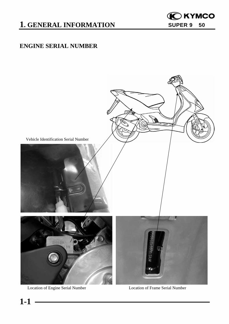
ENGINE SERIAL NUMBER
Location of Engine Serial Number Location of Frame Serial Number
Vehicle Identification Serial Number

1. GENERAL INFORMATION
1-2
SUPER 9 50
SPECIFICATIONS
Name & Model No. SH10DAOverall length 1850mmOverall width 700mmOverall height 1190mmWheel base 1295mmEngine type Water cooled 2-strokeDisplacement 49.4ccFuel Used 92# nonleaded gasoline
Front wheel 41Net weight (kg) Rear wheel 61
Total 102Front wheel 95
Gross weight(kg) Rear wheel 138Total 233
Front wheel 120/70-12Rear wheel 130/70-12
Ground clearance 160mmPerform- Braking distance (m) 4.4m /30km/HVance Min. turning radius 2150mm
Starting system Starting motor &kick starter
Type Gasoline,2-strokeCylinder arrangement Single cylinderCombustion chamber type Semi-sphereBore x stroke (mm) 39 x 41.4Compression ratio 7.2:1Compression pressure(kg/cm²-rpm) 11.8Max. output (ps/rpm) 3.6/6500Max. torque (N-m/rpm) 3.92/6000
Intake Open Automatic controlledPort (1mm) Close Automatic controlledtiming Exhaust Open
(1mm) CloseValve Intakeclearance (cold) ExhaustIdle speed (rpm) 2000±100rpm
Lubrication type Separate typeOil pump type Plunger typeOil filter type Full-flow filtrationOil capacity 1.7 litersExchanging capacity 1.4 liters
Cooling Type Water cooling
Air cleaner type & No Sponge wetGear oil capacity 0.12 litersFuel capacity 6.8 liters
Type PB
Piston dia. 13Venturi dia. 14 equivalent
Type CDIIgnition timing 13.5°±2°/2000rpm
Spark plug NGKBR8HSA
Spark plug gap 0.6~0.7mmBattery Capacity 12V4AHClutch Type Dry multi-disc clutch
Type Non-stage transmission
Operation Automatic centrifugaltype
Type Two-stage reductionReduction 1stratio 2nd
Front Caster angleAxle Connecting rodTire pressure Front 1.75(kg/cm²) Rear 2.25Turning Left 42.5°angle Right 42.5°
Brake system Front Disk braketype Rear Disk brake
Suspension Front Telescopetype Rear Unit swingShock absorber Front Telescopetype Rear Double swing
Frame type Under bone
Tires
Engine
Fuel System
Carburetor
Electrical Equipment
Power D
rive System
Transmis-
sion Gear
Reduction
Gear
Moving D
eviceD
amping
Device
LubricationS ystem
Ignition System

1. GENERAL INFORMATION
1-3
SUPER 9 50
Name & Model No. SF10DAOverall length 1850mmOverall width 700mmOverall height 1190mmWheel base 1295mmEngine type Air cooled 2-strokeDisplacement 49.4ccFuel Used 92# nonleaded gasoline
Front wheel 41.5Net weight (kg) Rear wheel 64.5
Total 106Front wheel 83.5
Gross weight(kg) Rear wheel 132.5Total 216
Front wheel 120/70-12Rear wheel 130/70-12
Ground clearance 160mmPerform- Braking distance (m) 4.4m /30km/HVance Min. turning radius 2150mm
Starting system Starting motor &kick starter
Type Gasoline,2-strokeCylinder arrangement Single cylinder, flatCombustion chamber type Semi-sphereBore x stroke (mm) 39 x 41.4Compression ratio 7.2:1Compression pressure(kg/cm²-rpm) 11.8Max. output (ps/rpm) 4.2/6500Max. torque (N-m/rpm) 4.9/6000
Intake Open Automatic controlledPort (1mm) Close Automatic controlledtiming Exhaust Open
(1mm) CloseValve Intakeclearance (cold) ExhaustIdle speed (rpm) 1900±100rpm
Lubrication type Separate typeOil pump type Plunger typeOil filter type Full-flow filtrationOil capacity 1.7 litersExchanging capacity 1.4 liters
Cooling Type Air cooling
Air cleaner type & No Sponge wetGear oil capacity 0.12 litersFuel capacity 6.8 liters
Type PB
Piston dia. 13Venturi dia. 14 equivalent
Type CDIIgnition timing 13.5°±2°/2000rpm
Spark plug NGKBR8HSA
Spark plug gap 0.6~0.7mmBattery Capacity 12V4AHClutch Type Dry multi-disc clutch
Type Non-stage transmission
Operation Automatic centrifugaltype
Type Two-stage reductionReduction 1stratio 2nd
Front Caster angleAxle Connecting rodTire pressure Front 1.75(kg/cm²) Rear 2.25Turning Left 42.5°angle Right 42.5°
Brake system Front Disk braketype Rear Expanding brake
Suspension Front Telescopetype Rear Unit swingShock absorber Front Telescopetype Rear Double swing
Frame type Under bone
Tires
Engine
Fuel System
Carburetor
Electrical Equipment
Power D
rive System
Transmis-
sion Gear
Reduction
Gear
Moving D
eviceD
amping
Device
LubricationS ystem
Ignition System

1. GENERAL INFORMATION
1-4
SUPER 9 50
SERVICE PRECAUTIONSMake sure to install new gaskets, O-rings,circlips, cotter pins, etc. whenreassembling.
When tightening bolts or nuts, begin withlarger-diameter to smaller ones at severaltimes, and tighten to the specified torquediagonally.
Use genuine parts and lubricants.
When servicing the motorcycle, be sureto use special tools for removal andinstallation.
After disassembly, clean removed parts.Lubricate sliding surfaces with engine oilbefore reassembly.
KYMCO
KYMCO KYMCO
1. GENERAL INFORMATION
1-5
SUPER 9 50
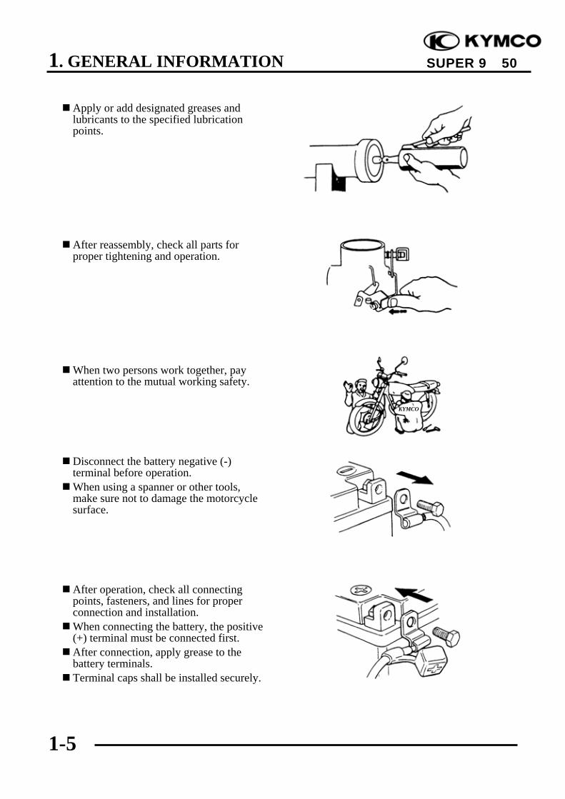
Apply or add designated greases andlubricants to the specified lubricationpoints.
After reassembly, check all parts forproper tightening and operation.
When two persons work together, payattention to the mutual working safety.
Disconnect the battery negative (-)terminal before operation.When using a spanner or other tools,make sure not to damage the motorcyclesurface.
After operation, check all connectingpoints, fasteners, and lines for properconnection and installation.When connecting the battery, the positive(+) terminal must be connected first.After connection, apply grease to thebattery terminals.Terminal caps shall be installed securely.
KYMCO

1. GENERAL INFORMATION
1-6
SUPER 9 50
If the fuse is burned out, find the causeand repair it. Replace it with a new oneaccording to the specified capacity.
After operation, terminal caps shall beinstalled securely.
When taking out the connector, the lockon the connector shall be released beforeoperation.
Hold the connector body whenconnecting or disconnecting it.Do not pull the connector wire.
Check if any connector terminal isbending, protruding or loose.
ConfirmCapacity

1. GENERAL INFORMATION
1-7
SUPER 9 50
The connector shall be insertedcompletely.If the double connector has a lock,lock it at the correct position.Check if there is any loose wire.
Before connecting a terminal, checkfor damaged terminal cover or loosenegative terminal.
Check the double connector cover forproper coverage and installation.
Insert the terminal completely.Check the terminal cover for propercoverage.Do not make the terminal cover openingface up.
Secure wire harnesses to the frame withtheir respective wire bands at thedesignated locations.Tighten the bands so that only theinsulated surfaces contact the wireharnesses.
Snapping!

1. GENERAL INFORMATION
1-8
SUPER 9 50
After clamping, check each wire to makesure it is secure.
Do not squeeze wires against the weld orits clamp.
After clamping, check each harness tomake sure that it is not interfering withany moving or sliding parts.
When fixing the wire harnesses, do notmake it contact the parts which willgenerate high heat.
Route wire harnesses to avoid sharpedges or corners. Avoid the projectedends of bolts and screws.Route wire harnesses passing through theside of bolts and screws. Avoid theprojected ends of bolts and screws.
No Contact !

1. GENERAL INFORMATION
1-9
SUPER 9 50
Route harnesses so they are neitherpulled tight nor have excessive slack.
Protect wires and harnesses withelectrical tape or tube if they contact asharp edge or corner.
When rubber protecting cover is used toprotect the wire harnesses, it shall beinstalled securely.
Do not break the sheath of wire.If a wire or harness is with a brokensheath, repair by wrapping it withprotective tape or replace it.
When installing other parts, do not pressor squeeze the wires.
Do not pull tootight!
Do not press orsqueeze the wire.

1. GENERAL INFORMATION
1-10
SUPER 9 50
After routing, check that the wireharnesses are not twisted or kinked.
Wire harnesses routed along withhandlebar should not be pulled tight,have excessive slack or interfere withadjacent or surrounding parts in allsteering positions.
When a testing device is used, make sureto understand the operating methodsthoroughly and operate according to theoperating instructions.
Be careful not to drop any parts.
When rust is found on a terminal, removethe rust with sand paper or equivalentbefore connecting.
Do you understand theinstrument? Is theinstrument set
l ?
Remove Rust !

1. GENERAL INFORMATION
1-11
SUPER 9 50
Symbols:The following symbols represent theservicing methods and cautions includedin this service manual.
: Apply engine oil to thespecified points. (Usedesignated engine oil forlubrication.)
: Apply grease forlubrication.
: Transmission Gear Oil(90#)
: Use special tool.
: Caution
: Warning
Special
Engine Oil
Grease
Gear Oil
*
1. GENERAL INFORMATION
1-12
SUPER 9 50
SERVICE INFORMATION
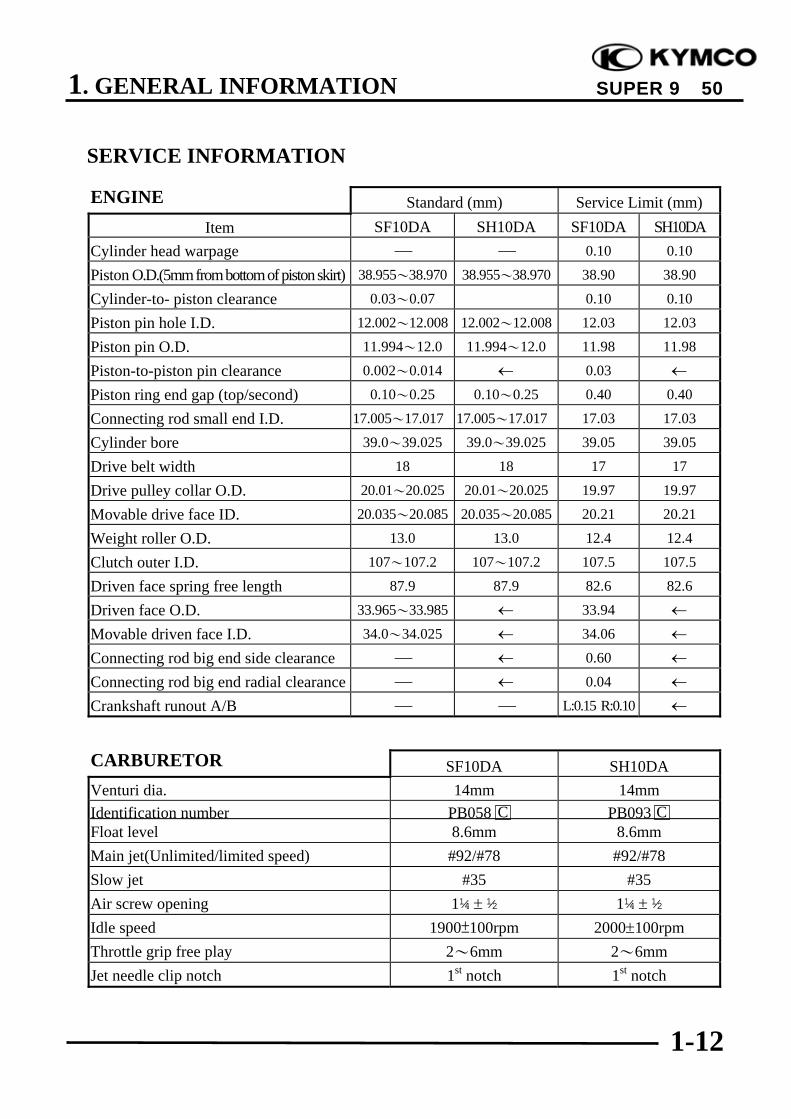
ENGINE Standard (mm) Service Limit (mm)Item SF10DA SH10DA SF10DA SH10DA
Cylinder head warpage ⎯ ⎯ 0.10 0.10
Piston O.D.(5mm from bottom of piston skirt) 38.955~38.970 38.955~38.970 38.90 38.90
Cylinder-to- piston clearance 0.03~0.07 0.10 0.10
Piston pin hole I.D. 12.002~12.008 12.002~12.008 12.03 12.03
Piston pin O.D. 11.994~12.0 11.994~12.0 11.98 11.98
Piston-to-piston pin clearance 0.002~0.014 ← 0.03 ←
Piston ring end gap (top/second) 0.10~0.25 0.10~0.25 0.40 0.40
Connecting rod small end I.D. 17.005~17.017 17.005~17.017 17.03 17.03
Cylinder bore 39.0~39.025 39.0~39.025 39.05 39.05
Drive belt width 18 18 17 17
Drive pulley collar O.D. 20.01~20.025 20.01~20.025 19.97 19.97
Movable drive face ID. 20.035~20.085 20.035~20.085 20.21 20.21
Weight roller O.D. 13.0 13.0 12.4 12.4
Clutch outer I.D. 107~107.2 107~107.2 107.5 107.5
Driven face spring free length 87.9 87.9 82.6 82.6
Driven face O.D. 33.965~33.985 ← 33.94 ←
Movable driven face I.D. 34.0~34.025 ← 34.06 ←
Connecting rod big end side clearance ⎯ ← 0.60 ←
Connecting rod big end radial clearance ⎯ ← 0.04 ←
Crankshaft runout A/B ⎯ ⎯ L:0.15 R:0.10 ←
CARBURETOR SF10DA SH10DAVenturi dia. 14mm 14mmIdentification number PB058 PB093Float level 8.6mm 8.6mmMain jet(Unlimited/limited speed) #92/#78 #92/#78Slow jet #35 #35Air screw opening 1¼ ± ½ 1¼ ± ½Idle speed 1900±100rpm 2000±100rpmThrottle grip free play 2~6mm 2~6mmJet needle clip notch 1st notch 1st notch
CC
1. GENERAL INFORMATION
1-13
SUPER 9 50
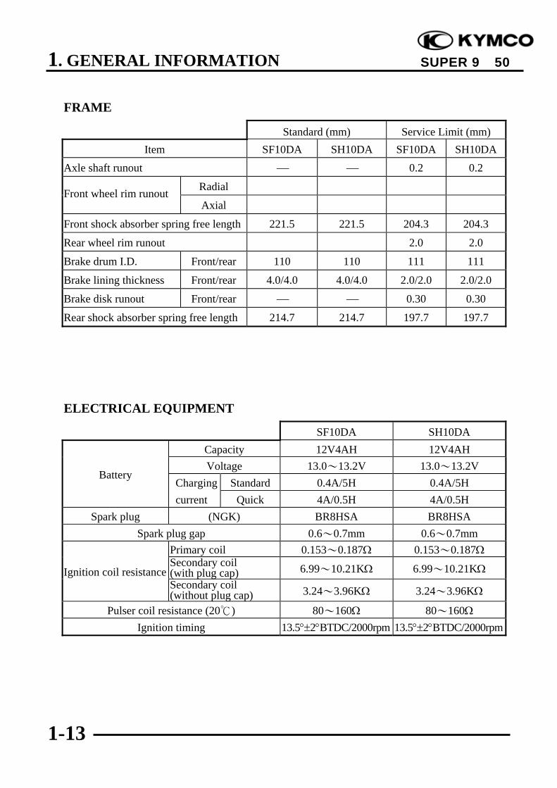
FRAME
Standard (mm) Service Limit (mm)Item SF10DA SH10DA SF10DA SH10DA
Axle shaft runout ⎯ ⎯ 0.2 0.2
RadialFront wheel rim runoutAxial
Front shock absorber spring free length 221.5 221.5 204.3 204.3
Rear wheel rim runout 2.0 2.0
Brake drum I.D. Front/rear 110 110 111 111
Brake lining thickness Front/rear 4.0/4.0 4.0/4.0 2.0/2.0 2.0/2.0
Brake disk runout Front/rear ⎯ ⎯ 0.30 0.30
Rear shock absorber spring free length 214.7 214.7 197.7 197.7
ELECTRICAL EQUIPMENT
SF10DA SH10DACapacity 12V4AH 12V4AHVoltage 13.0~13.2V 13.0~13.2V
Charging Standard 0.4A/5H 0.4A/5HBattery
current Quick 4A/0.5H 4A/0.5HSpark plug (NGK) BR8HSA BR8HSA
Spark plug gap 0.6~0.7mm 0.6~0.7mmPrimary coil 0.153~0.187Ω 0.153~0.187ΩSecondary coil(with plug cap) 6.99~10.21KΩ 6.99~10.21KΩIgnition coil resistanceSecondary coil(without plug cap) 3.24~3.96KΩ 3.24~3.96KΩ
Pulser coil resistance (20) 80~160Ω 80~160ΩIgnition timing 13.5°±2°BTDC/2000rpm 13.5°±2°BTDC/2000rpm
1. GENERAL INFORMATION
1-14
SUPER 9 50
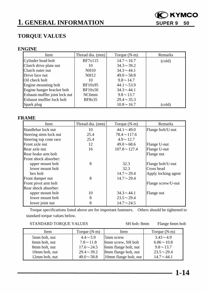
TORQUE VALUES
ENGINEItem Thread dia. (mm) Torque (N-m) Remarks
Cylinder head boltClutch drive plate nutClutch outer nutDrive face nutOil check boltEngine mounting boltEngine hanger bracket boltExhaust muffler joint lock nutExhaust muffler lock boltSpark plug
BF7x11510
NH10NH12
10BF10x95BF10x50NC6mmBF8x35
14.7~16.734.3~39.234.3~44.149.0~58.89.8~14.744.1~53.934.3~44.19.8~13.729.4~35.310.8~16.7
(cold)
(cold)
FRAMEItem Thread dia. (mm) Torque (N-m) Remarks
Handlebar lock nutSteering stem lock nutSteering top cone raceFront axle nutRear axle nutRear brake arm boltFront shock absorber: upper mount bolt lower mount bolt hex boltFront damper nutFront pivot arm boltRear shock absorber: upper mount bolt lower mount bolt lower joint nut
1025.425.41216
8
8
1088
44.1~49.078.4~117.64.9~12.749.0~68.6
107.8~127.4
32.332.3
14.7~29.414.7~29.4
34.3~44.123.5~29.414.7~24.5
Flange bolt/U-nut
Flange U-nutFlange U-nutFlange nut
Flange bolt/U-nutCross headApply locking agent
Flange screw/U-nut
Flange nut
Torque specifications listed above are for important fasteners. Others should be tightened tostandard torque values below.
STANDARD TORQUE VALUES SH bolt: 8mm Flange 6mm bolt
Item Torque (N-m) Item Torque (N-m) 5mm bolt, nut 6mm bolt, nut 8mm bolt, nut 10mm bolt, nut 12mm bolt, nut
4.4~5.97.8~11.817.6~24.529.4~39.249.0~58.8
5mm screw6mm screw, SH bolt6mm flange bolt, nut8mm flange bolt, nut10mm flange bolt, nut
3.43~4.96.86~10.89.8~13.723.5~29.414.7~44.1

1. GENERAL INFORMATION
1-15
SUPER 9 50
SPECIAL TOOLS
Tool Name Tool No. Remarks
Universal bearing puller E030 Crankshaft bearing removal
Lock nut socket wrench F001 Top cone race holding
Lock nut wrench, F001 Stem lock nut tightening
Crankcase puller E026 Crankcase disassembly
Bearing remover set, 12mm(Spindle assy, 15mm)(Remover weight)
E020 Drive shaft bearing removal/installation
Bearing remover set, 15mm(Spindle assy, 15mm)(Remover head, 15mm)(Remover shaft, 15mm)
E018 Drive shaft bearing removal/installation
Bearing outer driver, 28x30mm E014 Bearing installation
Clutch spring compressor E027 Driven pulley disassembly/assembly
Crankcase assembly collar E023 Driven shaft, crankshaft & crankcaseassembly
Crankcase assembly tool E024 Crankshaft & crankcase assembly
Ball race remover F005 Steering stem bearing races
Rear shock absorber compressor F004 Rear shock absorber disassembly/assembly
Universal holder E017 Flywheel holding
Flywheel puller E001 Flywheel removal
Pilot, 12mm E020 Drive shaft bearing installation
Bearing outer driver, 32x35mm E014 Drive shaft bearing installationFinal shaft bearing installation
Bearing outer driver, 37x40mm E014Drive shaft bearing installation Finalshaft bearing installation Crankshaftbearing installation
Outer driver, 24x26mm E014 Driven pulley bearing installation

1. GENERAL INFORMATION
1-16
SUPER 9 50
LUBRICATION POINTS
ENGINE
NO. Lubrication Points Lubricant Remarks1 Crankcase sliding & movable JASO-FC or API-TC2 Cylinder movable parts3 Transmission gear (final gear) SAE-90#4 Kick starter spindle bushing Grease5 Drive pulley movable parts Grease6 Starter pinion movable parts Grease
FRAMEApply clean engine oil or grease to cables and movable parts not specified. This will avoid
abnormal noise and rise the durability of the motorcycle.
Front/Rear Brake LeverSeat Lock
Throttle Cable
Main Stand Pivot
Grease Engine OilGrease
Speedometer Gear/Brake Cam/FrontShock AbsorberLower MountBushings/Pivot
Grease
Grease
Grease Engine Oil
Engine OilSpeedometer Cable
Rear WheelBearing
Rear Brake Cable

1. GENERAL INFORMATION
1-17
SUPER 9 50
Front StopSwitch
Rear StopSwitch
ThrottleCable
Radiator
Brake MasterCylinders
SpeedometerCable
Horn
Wire Harness
Water Hose
Reserve Cap
Resistors

1. GENERAL INFORMATION
1-18
SUPER 9 50
Front Brake Fluid Tube
Water Hose
IgnitionSwitch
Winker
Fuse Box
Starter Relay
CDI Unit
Regulator/Rectifier

1. GENERAL INFORMATION
1-19
SUPER 9 50
ThrottleCable
SpeedometerCable
Reserve Cap
Rear BrakeControl Cable
Water Hose
Wire Harness

1. GENERAL INFORMATION
1-20
SUPER 9 50
FuelFiller
Fuel TankBreather Tube
Fuel Filter
Ignition Coil
Thermostat
Fuel PumpVacuum Tube
Fuel Pump
Oil Filter
Oil Meter
Fuel Tube

1. GENERAL INFORMATION
1-21
SUPER 9 50
Auto BystarterWire
Ignition Coil
Fuel Pump
Fuel Tube
Fuel Unit Wire
Wire Harness
Spark PlugCap
Throttle Cable
Fuel Filter
Air Injection AirCleaner
Ignition Coil
Oil Meter
Oil Tube
Water Hose
1. GENERAL INFORMATION
1-22
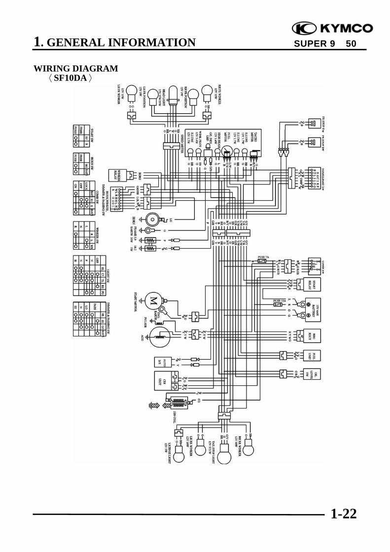
SUPER 9 50
WIRING DIAGRAM〈SF10DA〉
1. GENERAL INFORMATION
1-23
SUPER 9 50
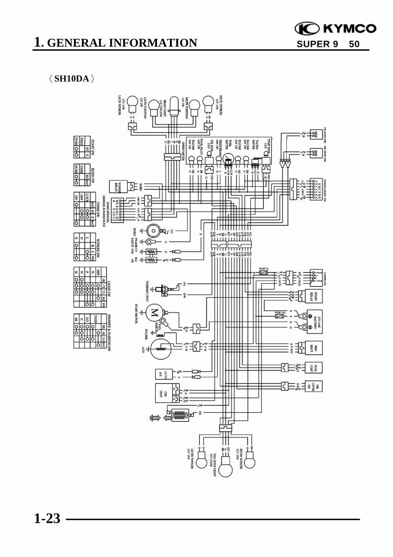
〈SH10DA〉

1. GENERAL INFORMATION
1-24
SUPER 9 50
TROUBLESHOOTING
ENGINE WILL NOT START OR IS HARD TO START
Empty fuel tankClogged float valveClogged charcoal canisterClogged fuel filterFaulty auto fuel valve
Faulty spark plugFouled spark plugFaulty CDI unitFaulty A.C. generatorBroken or shorted ignition coilBroken or shorted exciter coilFaulty ignition switch
Burned or worn cylinderpistonFaulty reed valveBlown cylinder head gasketLeaking crankcaseFaulty crankcase oil seal
Incorrectly adjusted idle speedAir leaking through intakepipeIncorrect ignition timing
Flooded carburetorThrottle valve excessivelyopen
Faulty auto bystarter
Check if fuel reachescarburetor by looseningdrain screw.
Remove spark plug andinstall it into spark plugcap to test spark byconnecting it to engineground.
Inspection/Adjustment Symptom Probable Cause
Fuel reaches carburetor
Spark jumps
Dry spark plug
Not clogged
Normal compression
Engine does not fire
Fuel does not reach carburetor
Weak or no spark
Wet spark plug
Clogged
Low or no compression
Engine fires but does not start
Test cylindercompression.
Remove spark plug andinspect again.
Wait for 30 minutes andthen remove the carbu-retor auto choke circuithose and blow the hosewith mouth.
Start engine by follow-ing normal startingprocedure.

1. GENERAL INFORMATION
1-25
SUPER 9 50
ENGINE STOPS IMMEDIATELY AFTER IT STARTS
Empty fuel tankClogged float valveClogged charcoal canisterClogged fuel filterFaulty auto fuel valve
Fouled spark plugIncorrect heat range plug
Fouled spark plugFaulty CDI unitFaulty A.C. generatorFaulty ignition coilBroken or shorted hightension wireFaulty ignition switch
Worn cylinder and pistonringsBlown cylinder head gasketFlaws in cylinder headFaulty reed valveSeized piston
Clogged carburetor jets
Faulty CDI unit or A.C.generatorA.C.G. flywheel not aligned
Mixture too rich (turn screwout)Mixture too lean (turn screwin)
Check if fuel reachescarburetor by looseningdrain screw.
Inspection/Adjustment Symptom Probable Cause
Fuel reaches carburetor
Good spark
Remove spark plug andinstall it into spark plugcap to test spark byconnecting it to engineground.
Correct timing
Correctly adjusted
Plug not fouled ordiscolored
Normal compression
Not Clogged
Fuel does not reach carburetor
Weak or inter- mittent spark
Incorrect timing
Incorrectly adjusted
Plug fouled ordiscolored
Abnormal compression
Clogged
Test cylindercompression (using acompression gauge).
Check carburetor forclogging.
Check ignition timing.
Check carburetor airscrew adjustment.
Remove spark plug andinstall it into spark plugcap to test spark byconnecting it to engineground.

1. GENERAL INFORMATION
1-26
SUPER 9 50
Carburetor not securelytightenedFaulty intake manifold gasketDeformed or brokencarburetor O-ring
Broken cableDirty auto bystarterFaulty auto bystarter
Faulty auto bystarter
Inspection/Adjustment Symptom Probable Cause
No air leak
Not clogged
Clogged
Air leaks
Clogged
Not Clogged
Check carburetor gasketfor air leaks.
Connect auto bystarterwire to battery. Wait for5 minutes, then connecta hose to fuel enrichingcircuit and then blowthe hose with mouth.
Remove auto bystarterconnecting wire andcheck if bypass fuelline is clogged.
1. GENERAL INFORMATION
1-27
SUPER 9 50
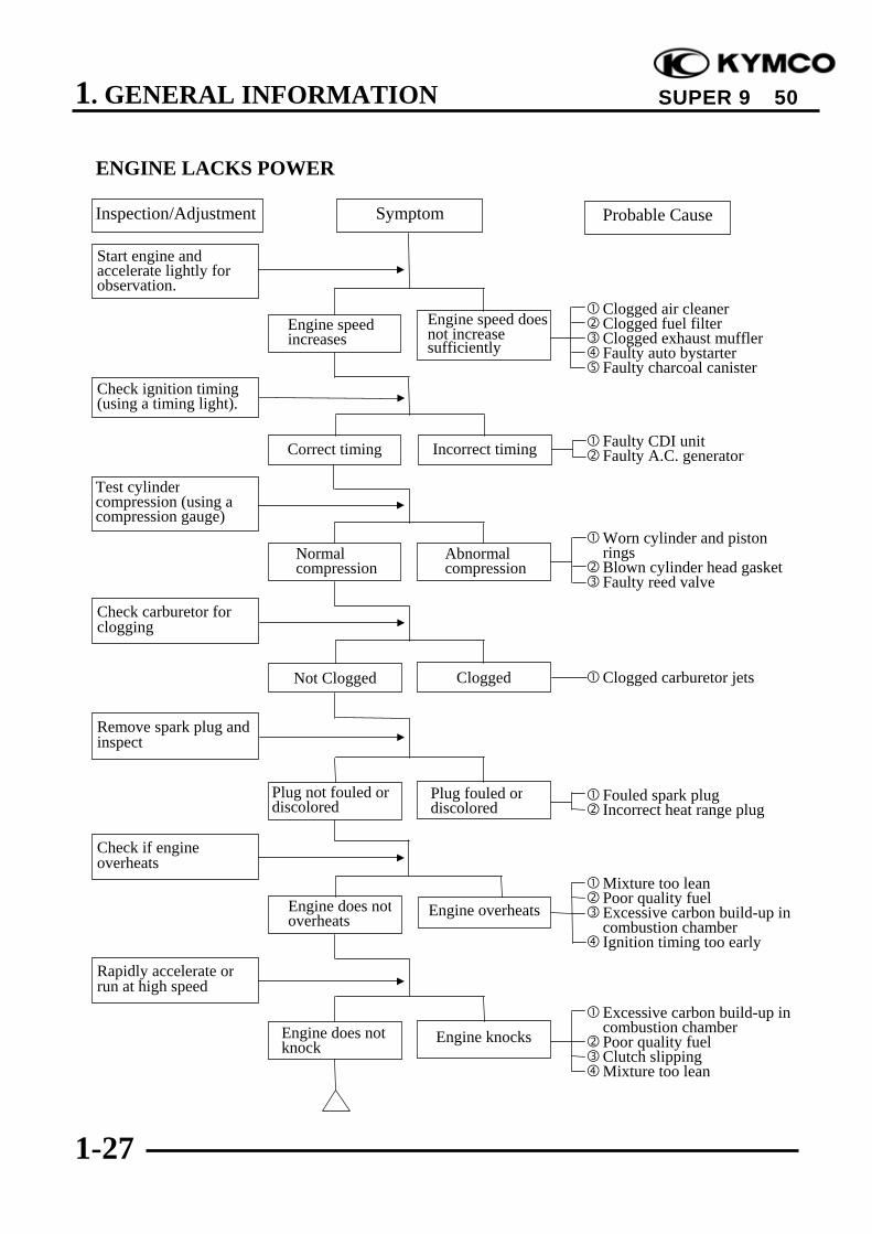
ENGINE LACKS POWER
Clogged air cleanerClogged fuel filterClogged exhaust mufflerFaulty auto bystarterFaulty charcoal canister
Faulty CDI unitFaulty A.C. generator
Worn cylinder and pistonringsBlown cylinder head gasketFaulty reed valve
Clogged carburetor jets
Fouled spark plugIncorrect heat range plug
Mixture too leanPoor quality fuelExcessive carbon build-up incombustion chamberIgnition timing too early
Excessive carbon build-up incombustion chamberPoor quality fuelClutch slippingMixture too lean
Inspection/Adjustment Symptom Probable Cause
Engine speed increases
Engine overheats
Correct timing
Engine does not knock
Plug not fouled ordiscolored
Normal compression
Not Clogged
Engine speed does not increase sufficiently
Engine does not overheats
Incorrect timing
Engine knocks
Plug fouled ordiscolored
Abnormal compression
Clogged
Start engine andaccelerate lightly forobservation.
Check ignition timing(using a timing light).
Rapidly accelerate orrun at high speed
Test cylindercompression (using acompression gauge)
Check carburetor forclogging
Remove spark plug andinspect
Check if engineoverheats

1. GENERAL INFORMATION
1-28
SUPER 9 50
POOR PERFORMANCE (ESPECIALLY AT IDLE AND LOW SPEEDS)
Faulty CDI unitFaulty A.C. generator
Mixture too rich (turn screwout)Mixture too lean (turn screwin)
Carburetor not securelytightenedFaulty intake manifold gasketDeformed carburetor O-ring
Faulty or fouled spark plugFaulty CDI unitFaulty A.C. generatorFaulty ignition coilBroken or shorted hightension wireFaulty ignition switch
Broken auto bystarter wireFaulty auto bystarter
Inspection/Adjustment Symptom Probable Cause
Clogged Not clogged
Remove spark plug andinstall it into spark plugcap to test spark byconnecting it to engineground.
Check ignition timing.
Connect auto bystarterwire to battery. Wait for5 minutes, then connecta hose to fuel enrichingcircuit and then blowthe hose with mouth.
Remove auto bystarterconnecting wire andcheck if bypass fuelline is clogged.
Check carburetor gasketfor air leaks.
Check carburetor airscrew adjustment.
Correct timing Incorrect timing
Correctly adjusted Incorrectly adjusted
No air leak Air leaks
Good spark Weak or inter- mittent spark
Not clogged Clogged

1. GENERAL INFORMATION
1-29
SUPER 9 50
POOR PERFORMANCE (AT HIGH SPEED)
Faulty CDI unit Loose A.C.G. stator
Faulty A.C. generator
Empty fuel tankClogged fuel tube or filterClogged charcoal canister
Clean and unclog
Broken auto bystarter wireFaulty auto bystarter
Faulty auto bystarter
Inspection/Adjustment Symptom Probable Cause
Clogged Not clogged
Check ignition timing.
Connect auto bystarterwire to battery. Wait for5 minutes, then connecta hose to fuel enrichingcircuit and then blowthe hose with mouth.
Remove auto bystarterconnecting wire andcheck if bypass fuelline is clogged.
Check carburetor jetsfor clogging.
Check auto fuel valvefor fuel supply.
Correct timing Incorrect timing
Fuel flows freely Fuel flow restricted
Not clogged Clogged
Not clogged Clogged

1. GENERAL INFORMATION
1-30
SUPER 9 50
CLUTCH, DRIVE AND DRIVEN PULLEYS
Worn or slipping drive beltBroken ramp plateBroken driven face springSeparated clutch liningDamaged driven pulley shaft splinesDamaged final gearSeized final gear
Broken shoe springClutch outer and clutch weight stuck
Seized pivot
Worn or slipping drive beltWorn weight rollersSeized drive pulley bearingsWeak driven face springWorn or seized driven pulley bearings
Worn or slipping drive beltWorn weight rollersWorn or seized driven pulley bearings
Oil or grease fouled drive beltWorn drive beltWeak driven face springWorn or seized driven pulley bearings
STEERING HANDLEBAR DOES NOT TRACK STRAIGHT
(Front and rear tire pressures are normal)
Steering stem nut too tightBroken steering steel balls
Excessive wheel bearing playBent rimLoose axle nut
Misaligned front and rear wheelsBent front fork
Engine starts but motor-cycle does not move
Engine lacks power atstart of a grade (poorslope performance)
Steering is heavy
Front or rear wheel iswobbling
Symptom
Symptom
Probable Cause
Probable Cause
Engine lacks power athigh speed
There is abnormal noiseor smell while running
Motorcycle creeps orengine starts but soonstops or seems to rushout (Rear wheel rotateswhen engine idles)
Steering handlebar pullsto one side
1. GENERAL INFORMATION
1-31
SUPER 9 50
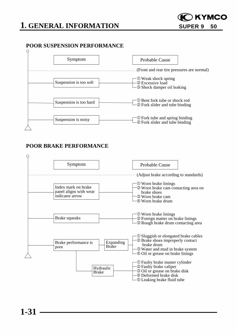
POOR SUSPENSION PERFORMANCE
(Front and rear tire pressures are normal)
Weak shock springExcessive loadShock damper oil leaking
Bent fork tube or shock rodFork slider and tube binding
Fork tube and spring bindingFork slider and tube binding
POOR BRAKE PERFORMANCE
(Adjust brake according to standards)
Worn brake liningsWorn brake cam contacting area onbrake shoesWorn brake camWorn brake drum
Worn brake liningsForeign matter on brake liningsRough brake drum contacting area
Sluggish or elongated brake cablesBrake shoes improperly contact brake drumWater and mud in brake systemOil or grease on brake linings
Faulty brake master cylinderFaulty brake caliperOil or grease on brake diskDeformed brake diskLeaking brake fluid tube
Suspension is too soft
Brake squeaks
Symptom
Symptom
Probable Cause
Probable Cause
Suspension is too hard
Suspension is noisy
Brake performance ispoor
Index mark on brakepanel aligns with wearindicator arrow
ExpandingBrake
HydraulicBrake

1. GENERAL INFORMATION
1-32
SUPER 9 50
Faulty
OIL METER
1. Motor oil indicator light does not come on when there is no motor oil (Ignition switch ON)
Burned out fuseWeak or dead batteryFaulty ignition switchLoose or disconnectedconnectorBroken wire harness
Burned out bulb
Loose wire connectorBroken wire harnessIncorrectly connected wire
Faulty floatBroken or shorted wire inmeter
2. Motor oil is sufficient but the indicator light remains on (Ignition switch ON)
Loose or disconnectedconnectorBroken wire harnessIncorrectly connected wire
Faulty floatBroken or shorted wire inmeter
Damaged oil tankForeign matters in oil tank
Inspection/Adjustment Symptom
Inspection/Adjustment
Probable Cause
Symptom Probable Cause
Signals operate properly
Signals dim, remainon or don‘t operate
Bulb lights Bulb does not light
Good Faulty
Remove oil meter andcheck operation ofindicator light bymoving float
Check connectors forproper connection.
Good
Good Faulty
Remove oil meter andcheck operation ofindicator light bymoving float
Check connectors forproper operation.
Connect indicator lightbulb to battery for bulbinspection.
Check battery circuit byoperating turn signals.
Good Faulty
Float up = Light offFloat down = Light on
Float up = Light offFloat down = Light on

1. GENERAL INFORMATION
1-33
SUPER 9 50
FUEL GAUGE1. Pointer does not register correctly (Ignition switch ON)
Burned out fuseWeak or dead batteryFaulty ignition switchLoose or disconnectedconnectorBroken wire harness
Faulty float
Broken or shorted fuel unitwire
Loose or disconnectedconnectorIncorrectly connectedconnectorBroken or shorted wire infuel gauge
2. Pointer fluctuates or swings (Ignition switch ON)
Burned out fuseWeak or dead batteryFaulty ignition switchLoose or disconnectedconnectorBroken wire harness
Poor contact in fuel unit
Insufficient damping oil infuel gauge
Loose or disconnectedconnectorBroken or shorted wire infuel gauge
Inspection/Adjustment
Inspection/Adjustment
Symptom
Symptom
Signals operate properly
Signals operate properly
Signals dim, remainon or don‘t operate
Signals dim, remainon or don‘t operate
Pointer does not move
Pointer does notmove
Good
Good
Pointer moves
Pointer moves
Pointer moves
Pointer does notmove in accord-ance with float
Faulty
Faulty
Pointer does notmove
Pointer moves inaccordance withfloat
Probable Cause
Probable Cause
Remove fuel unit andcheck operation ofpointer by moving floatup and down.
Check battery circuit byoperating turn signals.
Check operation ofpointer by opening andshorting fuel unitterminal on wireharness side.
Check connectors forproper connection.
Remove fuel unit andcheck operation ofpointer by moving floatup and down.
Check battery circuit byoperating turn signalsand horn.
Move float up anddown rapidly (1 round/sec.) to check theoperation of pointer.
Check connectors forproper connection.

1. GENERAL INFORMATION
1-34
SUPER 9 50
STARTER MOTOR1. Starter motor won‘t turn
Burned out fuseWeak or dead batteryFaulty stop switchLoose or disconnectedconnectorBroken or shorted ignitionswitch wire
Faulty or weak battery
Poor starter button connectionFaulty starter relayLoose or disconnectedconnector
Faulty starter motor
Faulty wire harness2. Starter motor turns slowly or idles
Weak or dead battery
Loose or disconnectedconnectorFaulty starter relay
Seized cylinderBroken or shorted startermotor cableFaulty starter pinion
3. Starter motor does not stop turning
Faulty starter pinionStarter relay shorted or stuckclosed
Inspection/Adjustment
Inspection/Adjustment
Inspection/Adjustment
Symptom
Symptom
Symptom
Signals operate properly
Signals operate properly
Signals dim, remainon or don‘t operate
Signals dim, remainon or don‘t operate
Stoplight does notcome on
Starter motor turns
Turns easily
Not stopped
Stoplight comes on
Starter does not turn
Hard to turn
Stopped
Relay operates properly
Starter motor turns slowly
Probable Cause
Probable Cause
Probable Cause
Relay does not operate
Starter motor turns normally
Check operation ofstop switch byapplying brake.
Check battery circuitby operating turnsignals.
Check battery circuitby operating turnsignals.
Turn ignition switchOFF.
Check operation ofstarter relay bydepressing starterbutton.
Connect startermotor directly tobattery.
Connect startermotor directly tobattery.
Rotate crankshaft.
2. EXHAUST MUFFLER/FRAME COVERS
2-0
SUPER 9 50
2 __________________________________________________________________________________
__________________________________________________________________________________
__________________________________________________________________________________
__________________________________________________________________________________
__________________________________________________________________________________
EXHAUST MUFFLER/FRAME COVERS__________________________________________________________________________________
SERVICE INFORMATION------------------------------------------------ 2- 1TROUBLESHOOTING----------------------------------------------------- 2- 1FRAME COVERS REMOVAL ------------------------------------------- 2- 2EXHAUST MUFFLER REMOVAL-------------------------------------- 2- 6
2

2. EXHAUST MUFFLER/FRAME COVERS
2-1
SUPER 9 50
SERVICE INFORMATION
GENERAL INSTRUCTIONS• When removing frame covers, use care not to pull them by force because the cover joint claws
may be damaged.• Make sure to route cables and harnesses according to the Cable & Harness Routing.
TORQUE VALUES Exhaust muffler lock bolt 34.3N-m Exhaust muffler joint lock nut 11.8N-m
TROUBLESHOOTINGNoisy exhaust muffler• Damaged exhaust muffler• Exhaust muffler joint air leaksLack of power• Caved exhaust muffler• Clogged exhaust muffler• Exhaust muffler air leaks

2. EXHAUST MUFFLER/FRAME COVERS
2-2
SUPER 9 50
FRAME COVERS REMOVALREAR CARRIER & HAND RAILREMOVALRemove the met-in box:First remove the two bolts and two nuts andfront two screws attaching the met-in box.Remove the met-in box.
Remove the three hex bolts attaching the rearcarrier.Remove the rear carrier and rear center cover.
FRAME BODY COVER REMOVALRemove the four screws attaching on thebottom of the frame body cover.Remove the bottom cover.
Hex Bolts
Rear Center Cover
screwsBolts/Nuts
Bottom Cover
Screws
2. EXHAUST MUFFLER/FRAME COVERS
2-3
SUPER 9 50
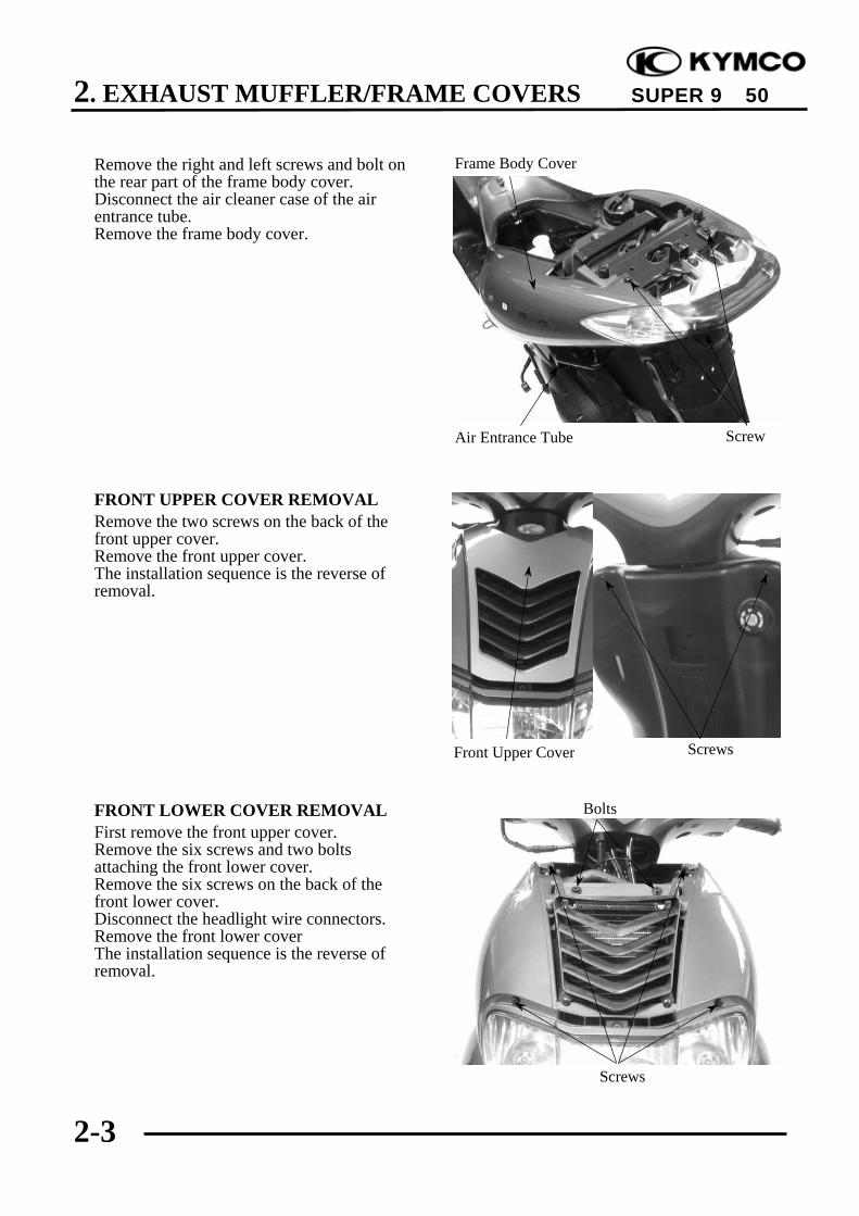
Remove the right and left screws and bolt onthe rear part of the frame body cover.Disconnect the air cleaner case of the airentrance tube.Remove the frame body cover.
FRONT UPPER COVER REMOVALRemove the two screws on the back of thefront upper cover.Remove the front upper cover.The installation sequence is the reverse ofremoval.
FRONT LOWER COVER REMOVALFirst remove the front upper cover.Remove the six screws and two boltsattaching the front lower cover.Remove the six screws on the back of thefront lower cover.Disconnect the headlight wire connectors.Remove the front lower coverThe installation sequence is the reverse ofremoval.
Air Entrance Tube Screw
Frame Body Cover
ScrewsFront Upper Cover
Screws
Bolts

2. EXHAUST MUFFLER/FRAME COVERS
2-4
SUPER 9 50
LEG SHIELD REMOVALRemove the front upper cover.Remove the front lower cover.Disconnect the leg shield and ignition switchcover.Remove the two bolts attaching the legshield.
Remove the leg shield.The installation sequence is the reverse ofremoval.
FRONT TOOL BOX REMOVALOpen the front tool box and remove the bolt.Remove the front tool box .
Leg Shield
Bolts
Front Tool Box
Ignition Switch
Bolt

2. EXHAUST MUFFLER/FRAME COVERS
2-5
SUPER 9 50
Remove the center cover by pulling thembackward.Remove the center cover.
FLOOR BOARD REMOVALRemove the screw and two bolts attaching thefront right and left side covers. Remove thetwo bottom cover attaching screws.
Remove the four bolts attaching the floorboard.Remove the floor board .The installation sequence is the reverse ofremoval.
Center Cover
Bolts
Screws Screws
Floor Board

2. EXHAUST MUFFLER/FRAME COVERS
2-6
SUPER 9 50
BOTTOM COVER REMOVALRemove the four screws attaching the bottomcover and inner bottom cover.Remove the bottom cover.
FRONT INNER FENDER REMOVALRemove the front upper cover. ( 2-3)Remove the front lower cover. ( 2-3)Remove the leg shield and floor board.Remove the bottom cover.Remove the screws which combines frontfender and the front axle nut to pull out theaxle.Remove the front fender and the front wheeland the speedometer gear unit.Separate inner fenders.The installation sequence is the reverse ofremoval.
EXHAUST MUFFLER REMOVALRemove the two exhaust muffler joint locknuts.Remove the two exhaust muffler lock bolts toremove the exhaust muffler.Remove the exhaust muffler joint packingcollar.The installation sequence is the reverse ofremoval.Torque: Exhaust muffler joint lock nut: 11.8N-m Exhaust muffler lock bolt: 34.3N-m
Fender
Screws
Screws
Bottom Cover
Lock Bolts Joint Lock Nut
NutInner Fender

2. EXHAUST MUFFLER/FRAME COVERS
2-7
SUPER 9 50
HANDLEBAR COVER REMOVALRemove the four screws attaching thehandlebar lower cover.Remove the handlebar lower cover.Remove the four screws attaching thehandlebar upper cover.Remove the handlebar upper cover.The installation sequence is the reverse ofremoval.
Screws
Screws

3. INSPECTION/ADJUSTMENT
3-0
SUPER 9 50
3 __________________________________________________________________________________
__________________________________________________________________________________
__________________________________________________________________________________
__________________________________________________________________________________
__________________________________________________________________________________
INSPECTION/ADJUSTMENT__________________________________________________________________________________
SERVICE INFORMATION------------------------------------------------ 3- 1INSPECTION AND MAINTENANCE SCHEDULE ------------------ 3- 2FUEL LINE/FUEL FILTER------------------------------------------------ 3- 5THROTTLE OPERATION------------------------------------------------- 3- 5AIR CLEANER -------------------------------------------------------------- 3- 6SPARK PLUG---------------------------------------------------------------- 3- 7IGNITION TIMING--------------------------------------------------------- 3- 7CYLINDER COMPRESSION --------------------------------------------- 3- 8FINAL REDUCTION GEAR OIL ---------------------------------------- 3- 9DRIVE BELT ---------------------------------------------------------------- 3- 9HEADLIGHT AIM ---------------------------------------------------------- 3-10COOLING SYSTEM-------------------------------------------------------- 3-10BRAKE SYSTEM ----------------------------------------------------------- 3-11NUTS/BOLTS/FASTENERS ---------------------------------------------- 3-13WHEELS/TIRES ------------------------------------------------------------ 3-13STEERING HANDLEBAR ------------------------------------------------ 3-13SUSPENSION---------------------------------------------------------------- 3-13LUBRICATION SYSTEM ------------------------------------------------- 3-14
3

3. INSPECTION/ADJUSTMENT
3-1
SUPER 9 50
SERVICE INFORMATION
GENERAL
! WARNING•Before running the engine, make sure that the working area is well-ventilated.
Never run the engine in a closed area. The exhaust contains poisonous carbonmonoxide gas which may cause death to people.
•Gasoline is extremely flammable and is explosive under some conditions. Theworking area must be well-ventilated and do not smoke or allow flames or sparksnear the working area or fuel storage area.
SPECIFICATIONS
ENGINEThrottle grip free play : 2~6mmSpark plug : NGK: BR8HSASpark plug gap : 0.6~0.7mmIdle speed : SH10DA:2000±100rpm SF10DA:1900±100rpm
Lubrication oil capacity: Cylinder compression : 11.8±2kg/cm² At disassembly : 1.7 liter Ignition timing : BTDC 13.5°±2°/2000rpm At change : 1.4 liter Coolant capacity : 1165ccGear oil capacity : Radiator capacity : 825cc At disassembly : 0.12 liter Reserve tank capacity : 340cc At change : 0.10 liter
CHASSISFront/rear brake free play: 20~30mm
TIRE
1 Rider 2 RidersFront 1.75kg/cm² 1.75kg/cm²
Rear 2.00kg/cm² 2.25kg/cm²
TIRE SPECIFICATION: Front : 120/70–12 Rear : 130/70–12
TORQUE VALUES Front axle nut : 49.0~68.6N-m Rear axle nut : 107.8~127.4N-m

3. INSPECTION/ADJUSTMENT
3-2
SUPER 9 50
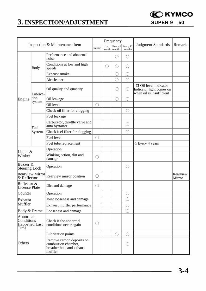
INSPECTION AND MAINTENANCE SCHEDULE(Note) 1. means time for inspection.
2. means regular replacement for the specified parts.This inspection and maintenance schedule is based upon average riding conditions.Machines subjected to serve use, or ridden in unusually dusty areas, require more frequentservicing.
FrequencyInspection & Maintenance Item
Preride 1stmonth
Every 6months
Every 12months
Judgment Standards Remarks
Check for looseness andvertical play Steering
handlebarOperating performance
Right/left turning angle
Suspension Damage
Check for front forkpivot installation
Checksteeringstem
Frontfork
Check front fork pivotfor looseness andabnormal noise
Checksteeringstem
Front/rear brake leverfree play
Free play:10~20mm
Brake lever operation BrakeLever
Brake performance
Lever/Cable
Looseness, abnormalnoise and damage
BrakeSystem
Disk-to-lining clearance
Brake disk(shoe) andlining wear Brake
disk/lining(Brake drum/shoe) Brake drum wear and
damage
Standard: Rear : 110 mmService Limits: Rear : 111 mm
MovingDevice Tire Tire pressure
Front Rear
1rider
1.75kg/cm²
2.25kg/cm²
TireSize
120/70-12
130/70-12

3. INSPECTION/ADJUSTMENT
3-3
SUPER 9 50
FrequencyInspection & Maintenance Item
Preride 1stmonth
Every 6months
Every 12months
Judgment Standards Remarks
Tire crack and damage
Tire groove andabnormal wear
Groove Depth: Front: 0.8mm Rear : 0.8mm
Imbedded objects,gravel, etc.
MovingDevice
Motor-cycle
Axle nut looseness
Torque Values: Front axle nut 49.0~68.6N-m Rear axle nut
107.8~127.4N-m
Axle nuttorque
Check wheel rim, rimedge and spoke plate fordamage
Rim runout at rim end:Front: Axial 2.0mm
Radial 2.0mmRear: Axial 2.0mm
Radial 2.0mm
Check front wheel bear-ing for excessive playand abnormal noise
Check front wheel bear-ing for excessive playand abnormal noise
FrameSpring Damage
Shockspringfreelength
Suspen-sion arm
Connecting parts loose-ness and arm damage
Shock Oil leakage and damage
DampingDevice
absorber Assembly parts loose-ness abnormal noise
Power Clutch Operation
DriveSystem Transmis-
sion case Oil leakage and oil level Oil level: Oil check bolt hole at lower hole edge
Rear wheeltransmis-sion case
Ignitiondevice Spark plug condition Plug gap: 0.6~0.7mm
ElectricalEquipment Battery Terminal connection
WiresLoose connection anddamage
3. INSPECTION/ADJUSTMENT
3-4
SUPER 9 50
FrequencyInspection & Maintenance Item
Preride 1stmonth
Every 6months
Every 12months
Judgment Standards Remarks
Performance and abnormalnoise
BodyConditions at low and highspeeds
Exhaust smoke
Air cleaner
Oil quality and quantity Oil level indicatorIndicator light comes onwhen oil is insufficient
Engine Oil leakage
Oil level
Lubrica-tionsystem
Check oil filter for clogging
Fuel leakageCarburetor, throttle valve andauto bystarter
Check fuel filter for clogging
Fuel level
FuelSystem
Fuel tube replacement Every 4 yearsOperationLights &
Winker Winking action, dirt anddamage
Buzzer &Steering Lock Operation
Rearview Mirror& Reflector Rearview mirror position Rearview
MirrorReflector &License Plate Dirt and damage
Counter Operation
Exhaust Joint looseness and damage
Muffler Exhaust muffler performance
Body & Frame Looseness and damage
AbnormalConditionsHappened LastTime
Check if the abnormalconditions occur again
Lubrication points
OthersRemove carbon deposits oncombustion chamber,breather hole and exhaustmuffler
3. INSPECTION/ADJUSTMENT
3-5
SUPER 9 50
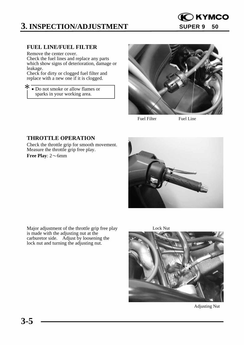
FUEL LINE/FUEL FILTERRemove the center cover.Check the fuel lines and replace any partswhich show signs of deterioration, damage orleakage.Check for dirty or clogged fuel filter andreplace with a new one if it is clogged.
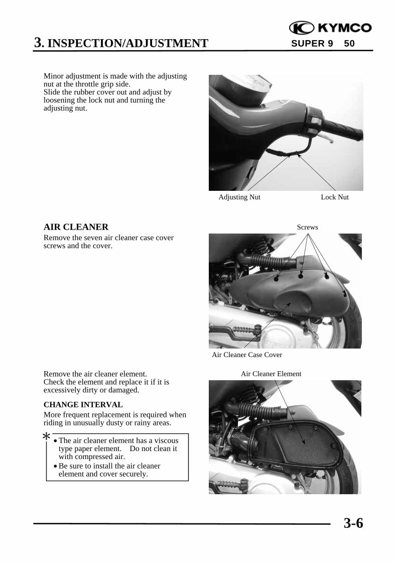
THROTTLE OPERATIONCheck the throttle grip for smooth movement.Measure the throttle grip free play.Free Play: 2~6mm
Major adjustment of the throttle grip free playis made with the adjusting nut at thecarburetor side. Adjust by loosening thelock nut and turning the adjusting nut.
Fuel Filter
• Do not smoke or allow flames orsparks in your working area.
*
Fuel Line
Lock Nut
Adjusting Nut
3. INSPECTION/ADJUSTMENT
3-6
SUPER 9 50
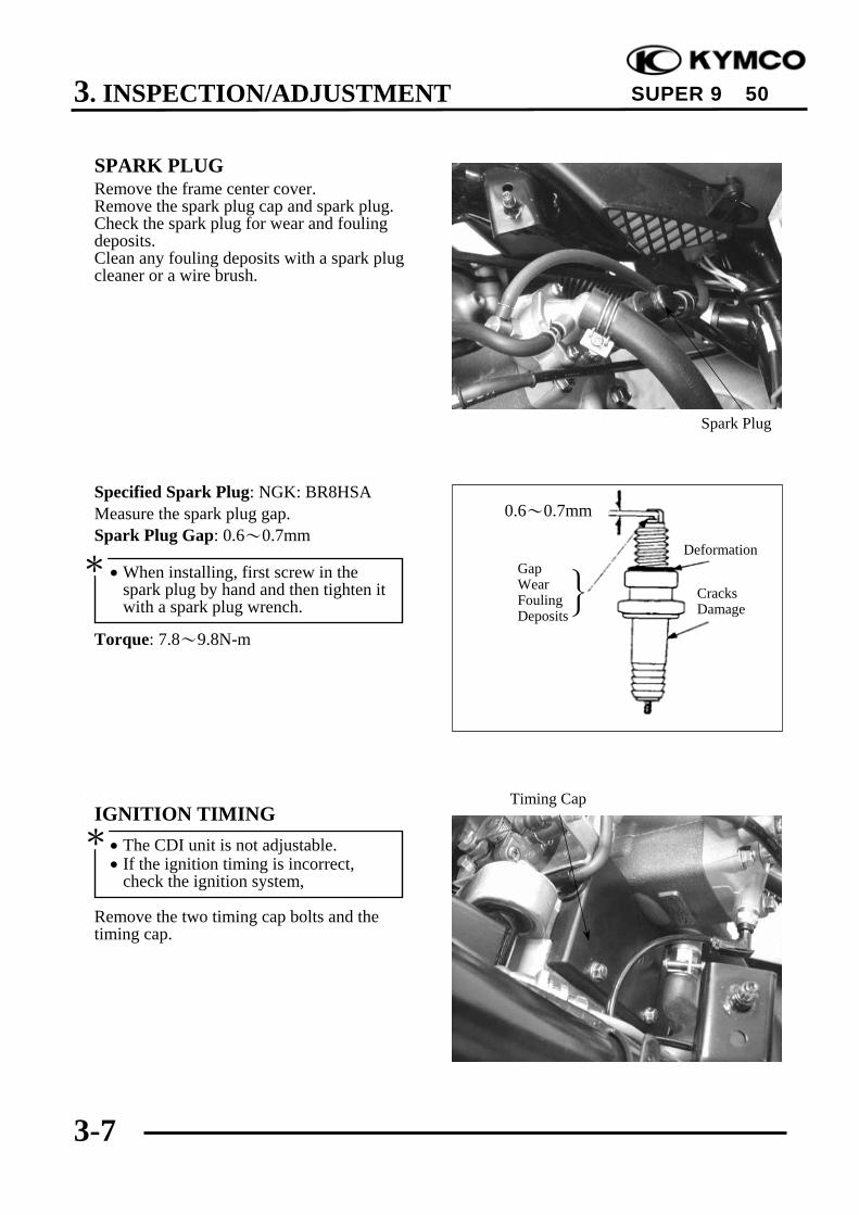
Minor adjustment is made with the adjustingnut at the throttle grip side.Slide the rubber cover out and adjust byloosening the lock nut and turning theadjusting nut.
AIR CLEANERRemove the seven air cleaner case coverscrews and the cover.
Remove the air cleaner element.Check the element and replace it if it isexcessively dirty or damaged.
CHANGE INTERVALMore frequent replacement is required whenriding in unusually dusty or rainy areas.
•The air cleaner element has a viscoustype paper element. Do not clean itwith compressed air.
•Be sure to install the air cleanerelement and cover securely.
*
Screws
Air Cleaner Case Cover
Air Cleaner Element
Adjusting Nut Lock Nut
3. INSPECTION/ADJUSTMENT
3-7
SUPER 9 50
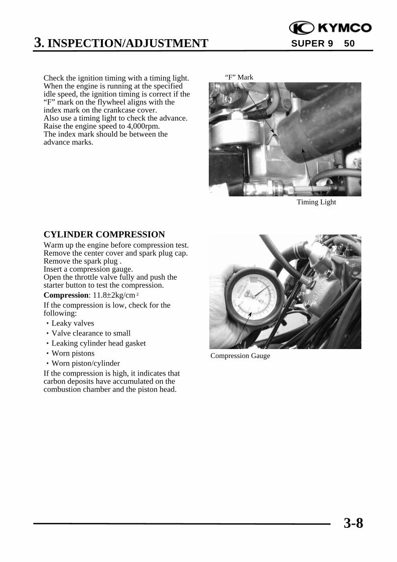
SPARK PLUGRemove the frame center cover.Remove the spark plug cap and spark plug.Check the spark plug for wear and foulingdeposits.Clean any fouling deposits with a spark plugcleaner or a wire brush.
Specified Spark Plug: NGK: BR8HSAMeasure the spark plug gap.Spark Plug Gap: 0.6~0.7mm
Torque: 7.8~9.8N-m
IGNITION TIMING
Remove the two timing cap bolts and thetiming cap.
}GapWearFoulingDeposits
CracksDamage
Deformation
Spark Plug
Timing Cap
0.6~0.7mm
• The CDI unit is not adjustable.• If the ignition timing is incorrect,
check the ignition system,
*
• When installing, first screw in thespark plug by hand and then tighten itwith a spark plug wrench.
*
3. INSPECTION/ADJUSTMENT
3-8
SUPER 9 50
Check the ignition timing with a timing light.When the engine is running at the specifiedidle speed, the ignition timing is correct if the“F” mark on the flywheel aligns with theindex mark on the crankcase cover.Also use a timing light to check the advance.Raise the engine speed to 4,000rpm.The index mark should be between theadvance marks.
CYLINDER COMPRESSIONWarm up the engine before compression test.Remove the center cover and spark plug cap.Remove the spark plug .Insert a compression gauge.Open the throttle valve fully and push thestarter button to test the compression.Compression: 11.8±2kg/cm²If the compression is low, check for thefollowing:‧Leaky valves‧Valve clearance to small‧Leaking cylinder head gasket‧Worn pistons‧Worn piston/cylinderIf the compression is high, it indicates thatcarbon deposits have accumulated on thecombustion chamber and the piston head.
Compression Gauge
Timing Light
“F” Mark

3. INSPECTION/ADJUSTMENT
3-9
SUPER 9 50
FINAL REDUCTION GEAR OIL
Stop the engine and remove the oil checkbolt.The oil level shall be at the oil check bolthole.If the oil level is low, add the recommendedoil SAE90# to the proper level.
Install the oil check bolt.
OIL CHANGERemove the oil check bolt.Remove the oil drain bolt and drain the oilthoroughly.Install the oil drain bolt.Torque: 9.8N-m
Fill the final reduction with the recommendedoil SAE90#.Gear Oil Capacity: At disassembly : 120cc At change : 100ccReinstall the oil check bolt and check for oilleaks.
DRIVE BELTRemove the left crankcase cover.Inspect the drive belt for cracks or excessivewear.Replace the drive belt with a new one ifnecessary and in accordance with theMaintenance Schedule.
Drive Belt
Oil Check Bolt Hole/Oil Filler
• Place the motorcycle on its main standon level ground.
*
Oil Drain Bolt/Sealing Washer
• Make sure that the sealing washer is ingood condition.
*
• Make sure that the sealing washer is ingood condition.
*
3. INSPECTION/ADJUSTMENT
3-10
SUPER 9 50
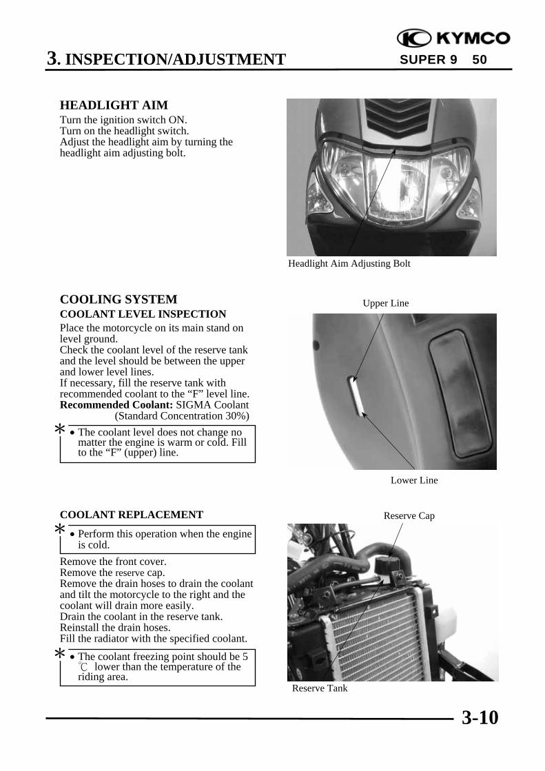
HEADLIGHT AIMTurn the ignition switch ON.Turn on the headlight switch.Adjust the headlight aim by turning theheadlight aim adjusting bolt.
COOLING SYSTEMCOOLANT LEVEL INSPECTIONPlace the motorcycle on its main stand onlevel ground.Check the coolant level of the reserve tankand the level should be between the upperand lower level lines.If necessary, fill the reserve tank withrecommended coolant to the “F” level line.Recommended Coolant: SIGMA Coolant (Standard Concentration 30%)
COOLANT REPLACEMENT
Remove the front cover.Remove the reserve cap.Remove the drain hoses to drain the coolantand tilt the motorcycle to the right and thecoolant will drain more easily.Drain the coolant in the reserve tank.Reinstall the drain hoses.Fill the radiator with the specified coolant.
Headlight Aim Adjusting Bolt
Lower Line
Upper Line
Reserve Cap
Reserve Tank
• The coolant level does not change nomatter the engine is warm or cold. Fillto the “F” (upper) line.
*
• The coolant freezing point should be 5 lower than the temperature of theriding area.
*
• Perform this operation when the engineis cold.
*
3. INSPECTION/ADJUSTMENT
3-11
SUPER 9 50
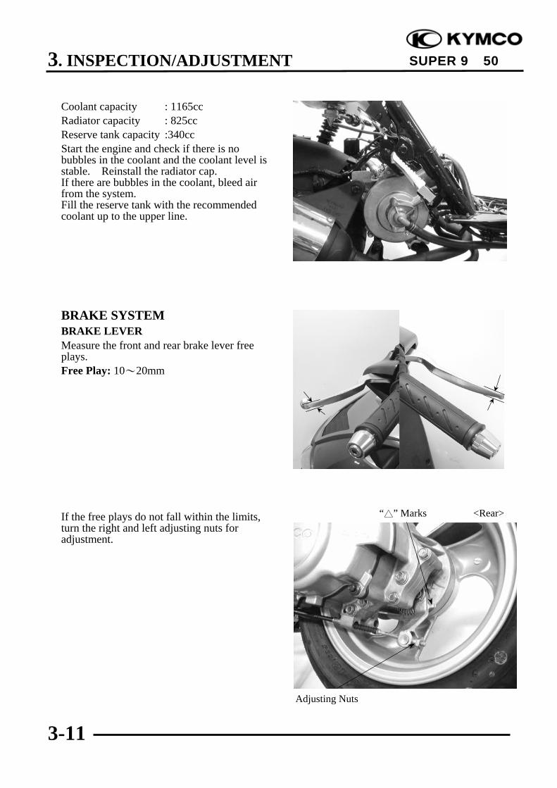
Coolant capacity : 1165ccRadiator capacity : 825ccReserve tank capacity :340ccStart the engine and check if there is nobubbles in the coolant and the coolant level isstable. Reinstall the radiator cap.If there are bubbles in the coolant, bleed airfrom the system.Fill the reserve tank with the recommendedcoolant up to the upper line.
BRAKE SYSTEMBRAKE LEVERMeasure the front and rear brake lever freeplays.Free Play: 10~20mm
If the free plays do not fall within the limits,turn the right and left adjusting nuts foradjustment.
Adjusting Nuts
“” Marks <Rear>
3. INSPECTION/ADJUSTMENT
3-12
SUPER 9 50
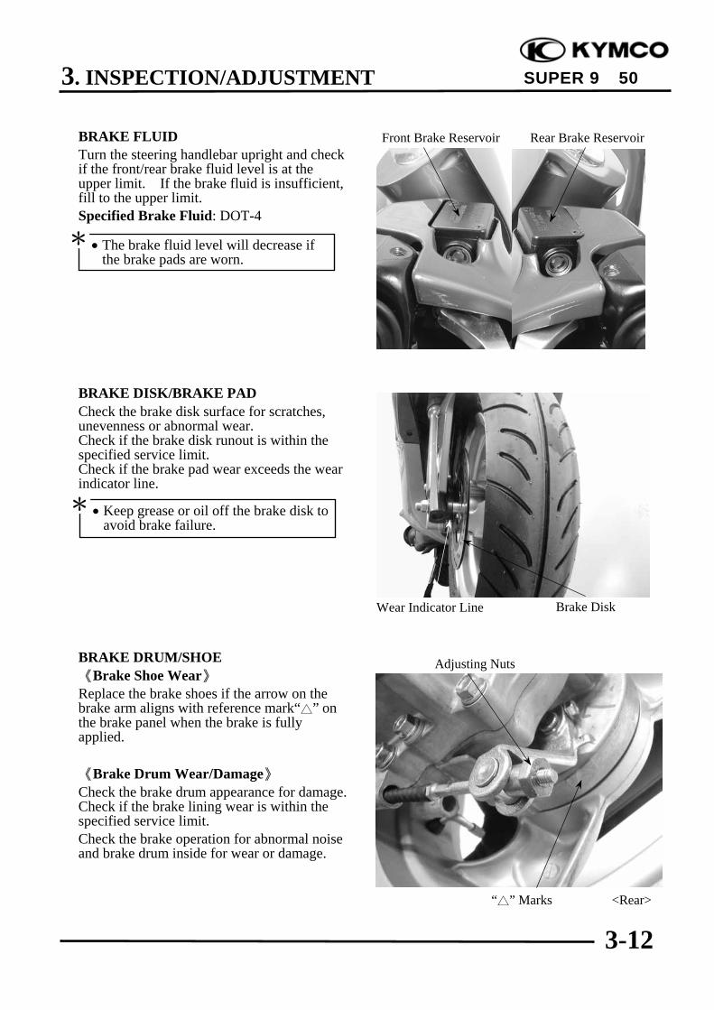
BRAKE FLUIDTurn the steering handlebar upright and checkif the front/rear brake fluid level is at theupper limit. If the brake fluid is insufficient,fill to the upper limit.Specified Brake Fluid: DOT-4
BRAKE DISK/BRAKE PADCheck the brake disk surface for scratches,unevenness or abnormal wear.Check if the brake disk runout is within thespecified service limit.Check if the brake pad wear exceeds the wearindicator line.
BRAKE DRUM/SHOE《Brake Shoe Wear》Replace the brake shoes if the arrow on thebrake arm aligns with reference mark“” onthe brake panel when the brake is fullyapplied.
《Brake Drum Wear/Damage》Check the brake drum appearance for damage.Check if the brake lining wear is within thespecified service limit.Check the brake operation for abnormal noiseand brake drum inside for wear or damage.
Front Brake Reservoir
Wear Indicator Line Brake Disk
Rear Brake Reservoir
“” Marks <Rear>
Adjusting Nuts
• The brake fluid level will decrease ifthe brake pads are worn.
*
• Keep grease or oil off the brake disk toavoid brake failure.
*

3. INSPECTION/ADJUSTMENT
3-13
SUPER 9 50
NUTS/BOLTS/FASTENERSCheck all important chassis nuts and bolts forlooseness.Tighten them to their specified torque valuesif any looseness is found.
WHEELS/TIRESCheck the tires for cuts, imbedded nails orother damages.Check the tire pressure.
Tire Pressure
1 Rider 2 Riders
Front 1.75kg/cm² 1.75kg/cm²
Rear 2.00kg/cm² 2.25kg/cm²
STEERING HANDLEBARRaise the front wheel off the ground andcheck that the steering handlebar rotatesfreely.If the handlebar moves unevenly, binds, orhas vertical movement, adjust the steeringhead bearing.
SUSPENSIONCheck the action of the front/rear shockabsorbers by compressing them several times.Check the entire shock absorber assembly foroil leaks, looseness or damage.Jack the rear wheel off the ground and movethe rear wheel sideways with force to see ifthe engine hanger bushings are worn.Replace the engine hanger bushings if there isany looseness.
Pressure Gauge
• Tire pressure should be checked whentires are cold.
*

3. INSPECTION/ADJUSTMENT
3-14
SUPER 9 50
LUBRICATION SYSTEM《Oil Filter Cleaning》Disconnect the oil tube at the oil pump sideand allow oil to drain into a clean container.Remove the tube clip at the oil tank side anddisconnect the oil tube.Remove the oil filter.
Clean the oil filter screen with compressedair.Install the oil filter in the reverse order ofremoval and fill the oil tank with specified oilup to the proper level.Bleed air from the oil pump and oil lines.
《Oil Pump Condition》
Open the throttle valve fully and check thatthe index mark on the pump body aligns withthe aligning mark on the oil pump controllever.Reference tip alignment within 1mm of indexmark on open side is acceptable.Start and idle the engine, then slowly openthe throttle to increase engine rpm and checkthe operation of the oil pump control lever.If adjustment is necessary, adjust the oilpump control cable by loosening the controlcable lock nut and turning the adjusting nut.After adjustment, tighten the lock nut.
If the oil pump is not synchronized properly,the following will occur:• Excessive white smoke or hard starting due
to pump control lever excessively open•Seized piston due to pump control lever
insufficiently open
Oil Filter Clip• Connect the oil tubes securely.• Install the tube clip at the oil tank side
and also install the clip to the lower oiltube that goes to the oil pump.
• Check for oil leaks.
*
Adjust oil pump control cable after thethrottle grip free play is adjusted.
*
Reference tip alignment within 1mm ofindex mark on open side is acceptable.However, the aligning mark on thecontrol lever must never be on theclosed side of the index mark, otherwiseengine damage will occur because ofinsufficient lubrication.
*
Filter Screen
Pump Body Index MarkAdjusting Nut
Lock Nut Control Lever Aligning Mark
4. LUBRICATION SYSTEM
4-0
SUPER 9 50
4 __________________________________________________________________________________
__________________________________________________________________________________
__________________________________________________________________________________
__________________________________________________________________________________
__________________________________________________________________________________
LUBRICATION SYSTEM__________________________________________________________________________________
SERVICE INFORMATION ................................................................ 4-1TROUBLESHOOTING ....................................................................... 4-1OIL PUMP REMOVAL....................................................................... 4-2OIL PUMP INSPECTION ................................................................... 4-2OIL PUMP INSTALLATION ............................................................. 4-3OIL PUMP BLEEDING....................................................................... 4-4OIL TANK ........................................................................................... 4-5
4

4. LUBRICATION SYSTEM
4-1
SUPER 9 50
SERVICE INFORMATION
GENERAL INSTRUCTIONS• Use care when removing and installing the oil pump not to allow dust and dirt to enter the engine
and oil line.• Do not attempt to disassemble the oil pump.• Bleed air from the oil pump if there is air between the oil pump and oil line.• If the oil is disconnected, refill the oil line with motor oil before connecting it.
SPECIFICATIONS• Recommended Motor Oil: SAE20W20# 2-stroke Motor Oil• Oil Capacity : 1.7 liter
Light comes on : 0.3 liter
TROUBLESHOOTINGExcessive white smoke or carbon deposits on spark plug• Oil pump not properly synchronized (excessive oil)• Poor quality oil
Engine overheating• Oil pump not properly adjusted (insufficient oiling)• Poor quality oil
Seized piston• No oil in tank or clogged oil line• Oil pump not properly adjusted (insufficient oiling)• Air in oil line• Faulty oil pump
Oil not flowing out of tank to engine• Clogged oil tank cap breather hole• Clogged oil filter
4. LUBRICATION SYSTEM
4-2
SUPER 9 50
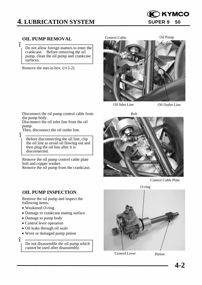
OIL PUMP REMOVAL
Remove the met-in box. ( 2-2)
Disconnect the oil pump control cable fromthe pump body.Disconnect the oil inlet line from the oilpump.Then, disconnect the oil outlet line.
Remove the oil pump control cable platebolt and copper washer.Remove the oil pump from the crankcase.
OIL PUMP INSPECTIONRemove the oil pump and inspect thefollowing items:• Weakened O-ring• Damage to crankcase mating surface• Damage to pump body• Control lever operation• Oil leaks through oil seals• Worn or damaged pump pinion
Do not allow foreign matters to enter thecrankcase. Before removing the oilpump, clean the oil pump and crankcasesurfaces.
*
Do not disassemble the oil pump whichcannot be used after disassembly.
*
Oil Outlet LineOil Inlet Line
Control Cable Oil Pump
Bolt
O-ring
PinionControl Lever
Control Cable Plate
Before disconnecting the oil line, clipthe oil line to avoid oil flowing out andthen plug the oil line after it isdisconnected.
*
4. LUBRICATION SYSTEM
4-3
SUPER 9 50
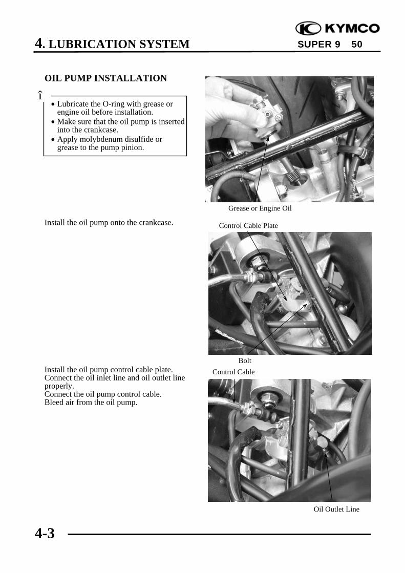
OIL PUMP INSTALLATION
Install the oil pump onto the crankcase.
Install the oil pump control cable plate.Connect the oil inlet line and oil outlet lineproperly.Connect the oil pump control cable.Bleed air from the oil pump.
• Lubricate the O-ring with grease orengine oil before installation.
• Make sure that the oil pump is insertedinto the crankcase.
• Apply molybdenum disulfide orgrease to the pump pinion.
*
Control Cable Plate
Grease or Engine Oil
BoltControl Cable
Oil Outlet Line
4. LUBRICATION SYSTEM
4-4
SUPER 9 50
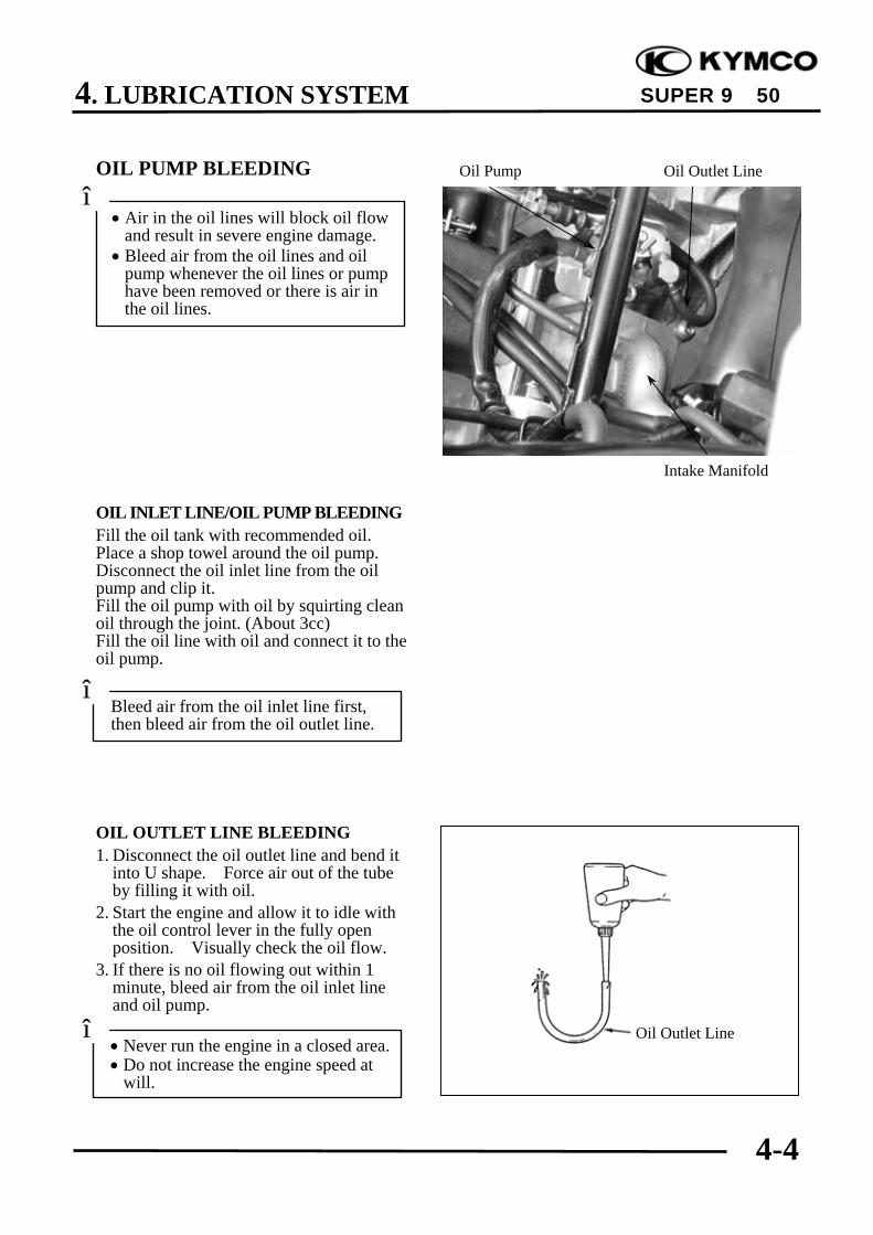
OIL PUMP BLEEDING
OIL INLET LINE/OIL PUMP BLEEDINGFill the oil tank with recommended oil.Place a shop towel around the oil pump.Disconnect the oil inlet line from the oilpump and clip it.Fill the oil pump with oil by squirting cleanoil through the joint. (About 3cc)Fill the oil line with oil and connect it to theoil pump.
OIL OUTLET LINE BLEEDING1. Disconnect the oil outlet line and bend it
into U shape. Force air out of the tubeby filling it with oil.
2. Start the engine and allow it to idle withthe oil control lever in the fully openposition. Visually check the oil flow.
3. If there is no oil flowing out within 1minute, bleed air from the oil inlet lineand oil pump.
• Air in the oil lines will block oil flowand result in severe engine damage.
• Bleed air from the oil lines and oilpump whenever the oil lines or pumphave been removed or there is air inthe oil lines.
*
Bleed air from the oil inlet line first,then bleed air from the oil outlet line.
*
• Never run the engine in a closed area.• Do not increase the engine speed at
will.
* Oil Outlet Line
Oil Pump Oil Outlet Line
Intake Manifold
4. LUBRICATION SYSTEM
4-5
SUPER 9 50
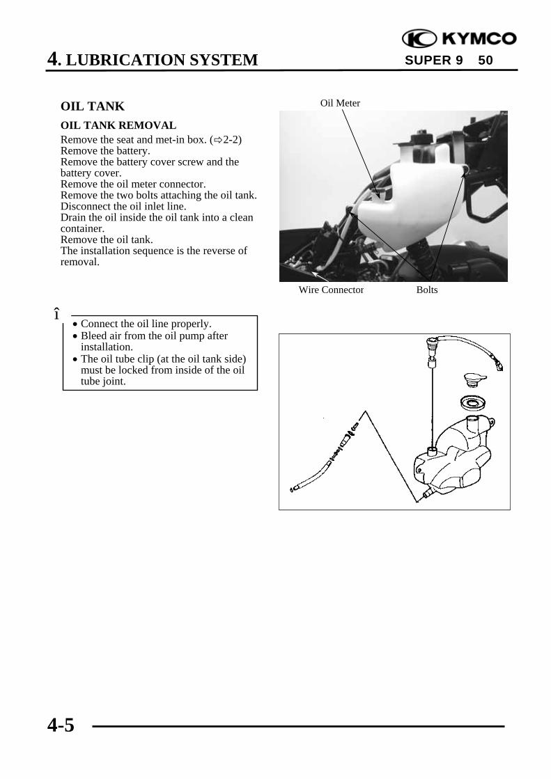
OIL TANKOIL TANK REMOVALRemove the seat and met-in box. ( 2-2)Remove the battery.Remove the battery cover screw and thebattery cover.Remove the oil meter connector.Remove the two bolts attaching the oil tank.Disconnect the oil inlet line.Drain the oil inside the oil tank into a cleancontainer.Remove the oil tank.The installation sequence is the reverse ofremoval.
• Connect the oil line properly.• Bleed air from the oil pump after
installation.• The oil tube clip (at the oil tank side)
must be locked from inside of the oiltube joint.
*
Oil Meter
BoltsWire Connector
5. ENGINE REMOVAL/INSTALLATION
5-0
SUPER 9 50
5 __________________________________________________________________________________
__________________________________________________________________________________
__________________________________________________________________________________
__________________________________________________________________________________
__________________________________________________________________________________
ENGINE REMOVAL/INSTALLATION__________________________________________________________________________________
SERVICE INFORMATION ................................................................ 5-1ENGINE REMOVAL .......................................................................... 5-2ENGINE INSTALLATION ................................................................. 5-4
5

5. ENGINE REMOVAL/INSTALLATION
5-1
SUPER 9 50
SERVICE INFORMATION
GENERAL INSTRUCTIONS• Parts requiring engine removal for servicing:
CrankcaseCrankshaft
TORQUE VALUESEngine mounting bolt 44.1~53.9N-mEngine hanger bracket bolt 44.1~53.9N-mRear shock absorber lower mount bolt 23.5~29.4N-mRear shock absorber upper mount bolt 34.3~44.1N-m

5. ENGINE REMOVAL/INSTALLATION
5-2
SUPER 9 50
ENGINE REMOVALRemove the frame body cover. ( 2-2)Remove the brake fluid tube bolt of the rearbrake caliper.Remove the rear brake caliper bolt and therear brake caliper.
Disconnect the oil pump control cable fromthe pump body.Disconnect the oil inlet line from the oilpump.
Disconnect the auto bystarter, A.C.generator, thermosensor wire couplers andstarter motor wire connectors.Disconnect the fuel tube and vacuum tubethat go to the carburetor from the auto fuelvalve.
Remove the spark plug cap.Drain the coolant. ( 3-10)Disconnect the water hose.
Rear Brake Caliper
Clamp
Oil Inlet Line
Oil Pump Control Cable AC Generator WireConnector
Spark Plug Cap
Water Hose
Auto Fuel Valve
Bolt
After the oil inlet line is disconnected,plug the oil line opening to prevent oilfrom flowing out.
*

5. ENGINE REMOVAL/INSTALLATION
5-3
SUPER 9 50
Remove the two bolts attaching the aircleaner case.Loosen the band between the air cleanerand carburetor to remove the air cleanercase.Remove the carburetor cap.Remove the rear shock absorber lowermount bolt.
Remove the right and left engine mountingnuts.Take out the right and left engine mountingbolts.Lift the frame upward to separate it fromthe engine and be careful not to damage .
ENGINE HANGER BRACKETREMOVALRemove the engine hanger bracket bolt andengine hanger bracket.The installation sequence is the reserve ofremoval.Torque:44.1~53.9N-m
Engine Mounting Nuts
Engine Hanger Bracket Bolt
Engine Hanger Bracket
Rear Shock Absorber Lower Mount Bolt
Carburetor Cap Air Cleaner Case
Bolt
Band

5. ENGINE REMOVAL/INSTALLATION
5-4
SUPER 9 50
ENGINE HANGER BRACKETINSPECTIONInspect the stopper rubbers and bushingsfor damage and replace with new ones ifnecessary.
ENGINE INSTALLATIONInstall the engine in the reverse order ofremoval.
Torque Values:Engine mounting bolt : 44.1~53.9N-mRear shock absorber lower mount bolt:
: 23.5~29.4N-m
Perform the following inspections andadjustments after installation.• Throttle cable• Oil pump control cable ( 4-2)• Rear brake system ( 3-11)• Oil pump bleeding ( 4-4)
Cables and wires should be routedproperly.
*
Bushings
Engine Hanger
Stopper Rubbers
6. CYLINDER HEAD/CYLINDER/PISTON
6-0
SUPER 9 50
6 __________________________________________________________________________________
__________________________________________________________________________________
__________________________________________________________________________________
__________________________________________________________________________________
__________________________________________________________________________________
CYLINDER HEAD/CYLINDER/PISTON__________________________________________________________________________________
SERVICE INFORMATION ................................................................ 6-1TROUBLESHOOTING ....................................................................... 6-1CYLINDER HEAD.............................................................................. 6-2CYLINDER/PISTON........................................................................... 6-6
6
6. CYLINDER HEAD/CYLINDER/PISTON
6-1
SUPER 9 50
SERVICE INFORMATIONGENERAL INSTRUCTIONS• The cylinder head, cylinder and piston can be serviced with the engine installed in the frame.• Before disassembly, clean the engine to prevent dust from entering the engine.• Remove all gasket material from the mating surfaces.• Do not use a driver to pry between the cylinder and cylinder head, cylinder and crankcase.• Do not damage the cylinder inside and the piston surface.• After disassembly, clean the removed parts before inspection. When assembling, apply the
specified engine oil to movable parts.
SPECIFICATIONS Standard (mm) Service Limit (mm)Item SH10DA SF10DA SH10DA SF10DA
Cylinder head warpage ⎯ 0.10Piston O.D.(5mm from bottom of piston 38.970~38.955 38.90
Cylinder-to- piston clearance 0.03~0.07 0.10
Piston pin hole I.D. 12.002~12.008 12.03
Piston pin O.D. 11.994~12.0 11.98
Piston-to-piston pin clearance 0.002~0.014 0.03
Piston ring end gap (top/second) 0.10~0.25 0.40
Connecting rod small end I.D. 17.005~17.017 17.03
Cylinder bore 39.0~39.025 39.05
TORQUE VALUESCylinder head bolt 14.7~16.66N-mExhaust muffler joint lock nut 9.8~13.72N-mExhaust muffler lock bolt 29.4~35.28N-mSpark plug 10.78~16.66N-m
TROUBLESHOOTINGCompression too low, hard startingor poor performance at low speed Abnormal noisy piston• Leaking cylinder head gasket • Worn cylinder and piston• Loose spark plug • Worn piston pin or piston pin hole• Worn, stuck or broken piston and piston rings • Worn connecting rod small end bearing• Worn or damaged cylinder and pistonCompression too high, overheatingor knocking Abnormal noisy piston rings• Excessive carbon build-up in cylinder head • Worn, stuck or broken piston rings
or on piston head • Worn or damaged cylinder

6. CYLINDER HEAD/CYLINDER/PISTON
6-2
SUPER 9 50
CYLINDER HEADREMOVAL 〈SH10AD〉Remove the rear carrier.Remove the frame body cover. ( 2-2)Drain the coolant.Disconnect the thermosensor wire from thethermosensor.Disconnect the water hose from thethermostat housing.
Remove the spark plug cap.Remove the two joint lock nuts on the frontof the exhaust muffler and then remove thetwo exhaust muffler lock bolts.The installation sequence is the reverse ofremoval.
Remove the spark plug.Remove the cylinder head bolts and thecylinder head.
Remove the cylinder head gasket.
Cylinder head Bolts
Exhaust muffler joint lock nut
Bolts
Cylinder HeadSpark Plug
Spark Plug Cap
When installing the exhaust muffler,first tighten the two nuts on the frontand then tighten the two bolts.
*
Loosen the bolts diagonally in 2 or 3times.
*

6. CYLINDER HEAD/CYLINDER/PISTON
6-3
SUPER 9 50
CYLINDER HEADREMOVAL 〈SF10DA〉Remove the rear carrier.Remove the frame body cover. ( 2-2)
Remove the spark plug cap.Remove the three bolts attaching the fancover to remove the fan cover.Remove the two joint lock nuts on the frontof the exhaust muffler and then remove thetwo exhaust muffler lock bolts.Remove the bolt attaching the engine hoodto remove the engine hood.The installation sequence is the reverse ofremoval.
Remove the spark plug.Remove the cylinder head bolts and thecylinder head.
Remove the cylinder head gasket.
Cylinder head Bolts
Spark Plug Cap
Fan Cover/Engine Hood
Bolts
Cylinder Head Spark Plug
When installing the exhaust muffler,first tighten the two nuts on the frontand then tighten the two bolts.
*
Loosen the bolts diagonally in 2 or 3times.
*

6. CYLINDER HEAD/CYLINDER/PISTON
6-4
SUPER 9 50
COMBUSTION CHAMBERDECABONIZINGRemove the carbon deposits from thecombustion chamber
CYLINDER HEAD INSPECTIONCheck the cylinder head for warpage with astraight edge and feeler gauge.Service Limit:SH10DA: 0.10mm replace if overSF10DA: 0.10mm replace if over
CYLINDER HEAD INSTALLATIONInstall the cylinder head on the cylinderproperly.
Install a new cylinder head gasket onto thecylinder.
Avoid damaging the combustion cham-ber wall and cylinder mating surface.
*
Cylinder head Gasket
Combustion Chamber
Mating Surface
Be careful not to damage the matingsurfaces.
*

6. CYLINDER HEAD/CYLINDER/PISTON
6-5
SUPER 9 50
Cylinder Head Bolts InstallationInstall and tighten the cylinder head boltsdiagonally in 2 or 3 times.Torque: 14.7~16.66N-mInstall the spark plug.Torque: 10.78~16.66N-m
Engine Hood InstallationInstall the engine hood. ( 6-3)Install the spark plug cap. ( 6-3)Perform the following inspections afterinstallation:• Compression test• Abnormal engine noise• Cylinder air leaks
Cylinder head Bolts
Cylinder HeadSpark Plug
Spark Plug
Bolts
Bolts
Engine Hood
6. CYLINDER HEAD/CYLINDER/PISTON
6-6
SUPER 9 50
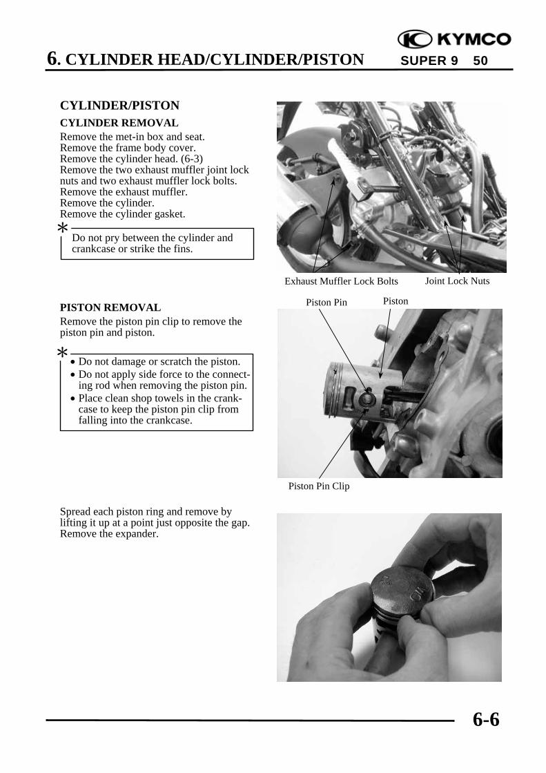
CYLINDER/PISTONCYLINDER REMOVALRemove the met-in box and seat.Remove the frame body cover.Remove the cylinder head. (6-3)Remove the two exhaust muffler joint locknuts and two exhaust muffler lock bolts.Remove the exhaust muffler.Remove the cylinder.Remove the cylinder gasket.
PISTON REMOVALRemove the piston pin clip to remove thepiston pin and piston.
Spread each piston ring and remove bylifting it up at a point just opposite the gap.Remove the expander.
• Do not damage or scratch the piston.• Do not apply side force to the connect-
ing rod when removing the piston pin.• Place clean shop towels in the crank-
case to keep the piston pin clip fromfalling into the crankcase.
*
Do not pry between the cylinder andcrankcase or strike the fins.
*
Piston Pin Clip
Exhaust Muffler Lock Bolts Joint Lock Nuts
PistonPiston Pin
6. CYLINDER HEAD/CYLINDER/PISTON
6-7
SUPER 9 50
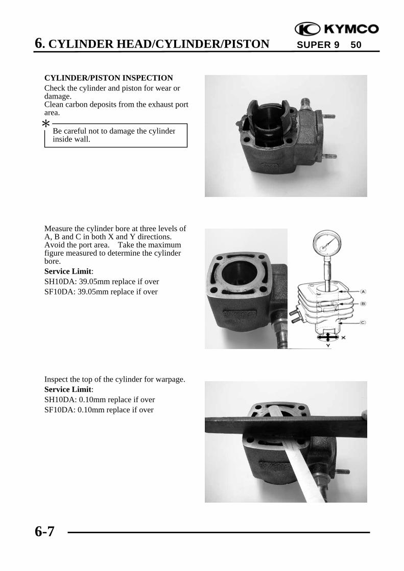
CYLINDER/PISTON INSPECTIONCheck the cylinder and piston for wear ordamage.Clean carbon deposits from the exhaust portarea.
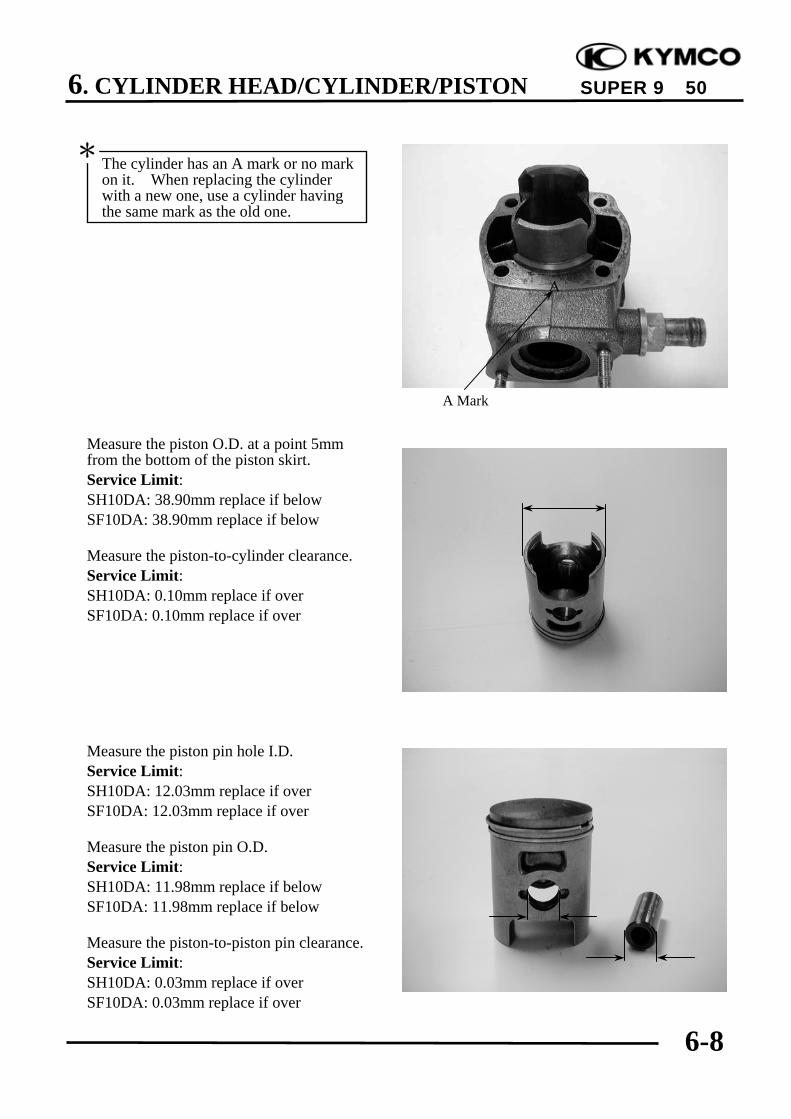
Measure the cylinder bore at three levels ofA, B and C in both X and Y directions.Avoid the port area. Take the maximumfigure measured to determine the cylinderbore.Service Limit:SH10DA: 39.05mm replace if overSF10DA: 39.05mm replace if over
Inspect the top of the cylinder for warpage.Service Limit:SH10DA: 0.10mm replace if overSF10DA: 0.10mm replace if over
Be careful not to damage the cylinderinside wall.
*
6. CYLINDER HEAD/CYLINDER/PISTON
6-8
SUPER 9 50
Measure the piston O.D. at a point 5mmfrom the bottom of the piston skirt.Service Limit:SH10DA: 38.90mm replace if belowSF10DA: 38.90mm replace if below
Measure the piston-to-cylinder clearance.Service Limit:SH10DA: 0.10mm replace if overSF10DA: 0.10mm replace if over
Measure the piston pin hole I.D.Service Limit:SH10DA: 12.03mm replace if overSF10DA: 12.03mm replace if over
Measure the piston pin O.D.Service Limit:SH10DA: 11.98mm replace if belowSF10DA: 11.98mm replace if below
Measure the piston-to-piston pin clearance.Service Limit:SH10DA: 0.03mm replace if overSF10DA: 0.03mm replace if over
The cylinder has an A mark or no markon it. When replacing the cylinderwith a new one, use a cylinder havingthe same mark as the old one.
*
A Mark

6. CYLINDER HEAD/CYLINDER/PISTON
6-9
SUPER 9 50
PISTON RING INSPECTIONMeasure each piston ring end gap.Service Limits: Top/SecondSH10DA: 0.40mm replace if overSF10DA: 0.40mm replace if over
CONNECTING ROD SMALL ENDINSPECTIONInstall the piston pin and bearing in theconnecting rod small end and check forexcessive play.Measure the connecting road small end I.D.Service Limit:SH10DA: 17.03mm replace if overSF10DA: 17.03mm replace if over
PISTON/CYLINDER INSTALLATIONFirst install the expander in the second ringgroove.Then install the top and second rings intheir respective ring grooves.The piston rings should be pressed into thegrooves with even force.After installation, check and make sure thateach ring is flush with the piston at severalpoints around the ring.A ring that will not compress means thatthe ring groove has carbon deposits in itand should be cleaned.
Set each piston ring squarely into thecylinder using the piston and measurethe end gap.
*
Expander
Top Ring (1st Ring)Piston
Second Ring
Piston RingFeeler Gauge

6. CYLINDER HEAD/CYLINDER/PISTON
6-10
SUPER 9 50
Install a new cylinder gasket on the matingsurface between the cylinder and crankcase.
Make sure that the ring end gaps arealigned with the piston ring pins in the ringgrooves.
Lubricate the cylinder inside and pistonrings with engine oil and install the pistoninto the cylinder while compressing thepiston rings.
Install the cylinder head.Torque: 14.7~16.66N-mInstall the exhaust muffler and tighten theexhaust muffler joint lock nuts.Torque: 9.8~13.72N-mTighten the exhaust muffler lock bolts.Torque: 29.4~35.28N-mInstall the frame covers.
Cylinder Gasket
Ring Pins
Be careful not to damage the piston.*

7. KICK STARTER/DRIVE PULLEY/CLUTCH/DRIVEN PULLEY
7-0
SUPER 9 50
7 __________________________________________________________________________________
__________________________________________________________________________________
__________________________________________________________________________________
__________________________________________________________________________________
__________________________________________________________________________________
KICK STARTER/DRIVE PULLEY/CLUTCH/DRIVEN PULLEY
__________________________________________________________________________________
SERVICE INFORMATION ................................................................ 7- 1TROUBLESHOOTING ....................................................................... 7- 1KICK STARTER.................................................................................. 7- 2DRIVE BELT....................................................................................... 7- 6DRIVE PULLEY.................................................................................. 7- 8STARTER PINION.............................................................................. 7-10CLUTCH/DRIVEN PULLEY.............................................................. 7-11
7
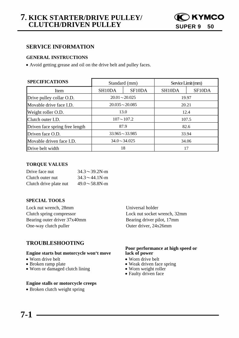
7. KICK STARTER/DRIVE PULLEY/CLUTCH/DRIVEN PULLEY
7-1
SUPER 9 50
SERVICE INFORMATION
GENERAL INSTRUCTIONS• Avoid getting grease and oil on the drive belt and pulley faces.
SPECIFICATIONS Standard (mm) Service Limit (mm)Item SH10DA SF10DA SH10DA SF10DA
Drive pulley collar O.D. 20.01~20.025 19.97
Movable drive face I.D. 20.035~20.085 20.21
Weight roller O.D. 13.0 12.4
Clutch outer I.D. 107~107.2 107.5
Driven face spring free length 87.9 82.6
Driven face O.D. 33.965~33.985 33.94
Movable driven face I.D. 34.0~34.025 34.06
Drive belt width 18 17
TORQUE VALUESDrive face nut 34.3~39.2N-mClutch outer nut 34.3~44.1N-mClutch drive plate nut 49.0~58.8N-m
SPECIAL TOOLSLock nut wrench, 28mm Universal holderClutch spring compressor Lock nut socket wrench, 32mmBearing outer driver 37x40mm Bearing driver pilot, 17mmOne-way clutch puller Outer driver, 24x26mm
TROUBLESHOOTINGPoor performance at high speed or
Engine starts but motorcycle won‘t move lack of power• Worn drive belt • Worn drive belt• Broken ramp plate • Weak driven face spring• Worn or damaged clutch lining • Worn weight roller
• Faulty driven face
Engine stalls or motorcycle creeps• Broken clutch weight spring
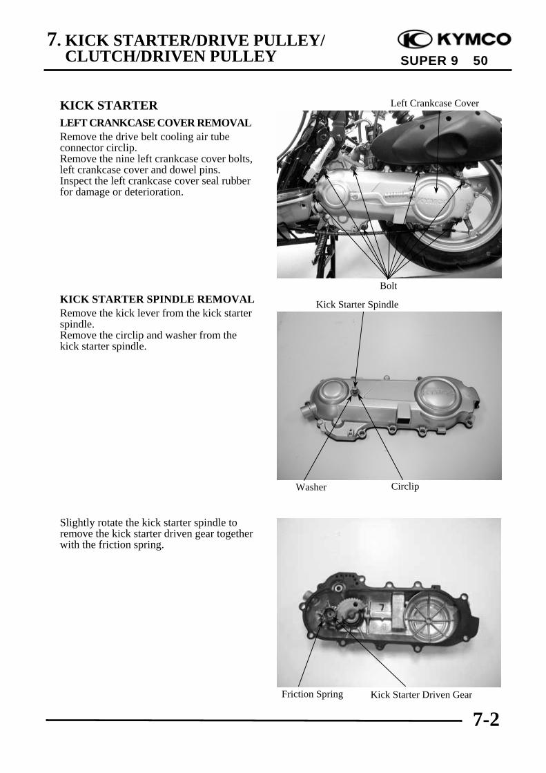
7. KICK STARTER/DRIVE PULLEY/CLUTCH/DRIVEN PULLEY
7-2
SUPER 9 50
KICK STARTERLEFT CRANKCASE COVER REMOVALRemove the drive belt cooling air tubeconnector circlip.Remove the nine left crankcase cover bolts,left crankcase cover and dowel pins.Inspect the left crankcase cover seal rubberfor damage or deterioration.
KICK STARTER SPINDLE REMOVALRemove the kick lever from the kick starterspindle.Remove the circlip and washer from thekick starter spindle.
Slightly rotate the kick starter spindle toremove the kick starter driven gear togetherwith the friction spring.
Kick Starter Spindle
Left Crankcase Cover
Bolt
Friction Spring Kick Starter Driven Gear
Washer Circlip
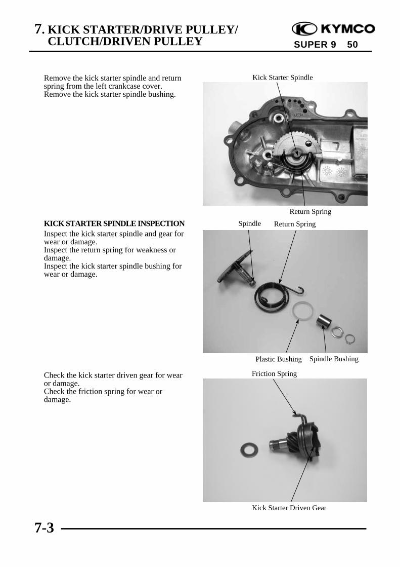
7. KICK STARTER/DRIVE PULLEY/CLUTCH/DRIVEN PULLEY
7-3
SUPER 9 50
Remove the kick starter spindle and returnspring from the left crankcase cover.Remove the kick starter spindle bushing.
KICK STARTER SPINDLE INSPECTIONInspect the kick starter spindle and gear forwear or damage.Inspect the return spring for weakness ordamage.Inspect the kick starter spindle bushing forwear or damage.
Check the kick starter driven gear for wearor damage.Check the friction spring for wear ordamage.
Kick Starter Spindle
Spindle
Friction Spring
Kick Starter Driven Gear
Plastic Bushing Spindle Bushing
Return Spring
Return Spring

7. KICK STARTER/DRIVE PULLEY/CLUTCH/DRIVEN PULLEY
7-4
SUPER 9 50
Inspect the kick starter spindle and drivengear forcing parts for wear or damage.
KICK STARTER INSTALLATIONInstall the kick starter spindle bushing andreturn spring onto the left crankcase cover.
Properly install the kick starter driven gearand friction spring as the figure shown.
If the hooks of the return spring can notbe installed properly, use a screw driverto press them into their locationsrespectively.
*
Kick Starter Spindle Forcing Part
Friction Spring
Kick Starter Driven Gear
Friction SpringKick Starter Spindle
Kick Starter Driven Gear Forcing Part
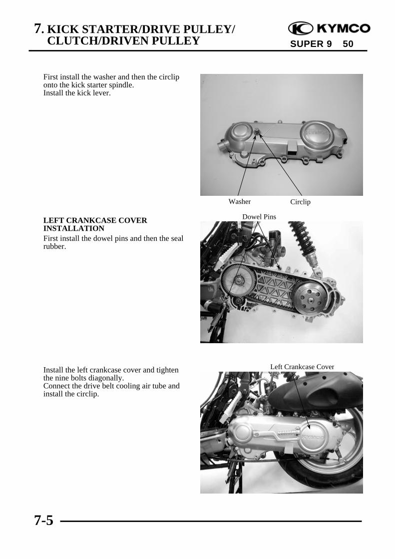
7. KICK STARTER/DRIVE PULLEY/CLUTCH/DRIVEN PULLEY
7-5
SUPER 9 50
First install the washer and then the circliponto the kick starter spindle.Install the kick lever.
LEFT CRANKCASE COVERINSTALLATIONFirst install the dowel pins and then the sealrubber.
Install the left crankcase cover and tightenthe nine bolts diagonally.Connect the drive belt cooling air tube andinstall the circlip.
Left Crankcase Cover
Dowel Pins
Washer Circlip
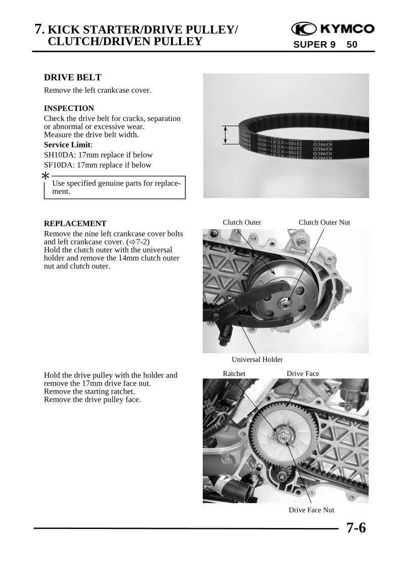
7. KICK STARTER/DRIVE PULLEY/CLUTCH/DRIVEN PULLEY
7-6
SUPER 9 50
DRIVE BELTRemove the left crankcase cover.
INSPECTIONCheck the drive belt for cracks, separationor abnormal or excessive wear.Measure the drive belt width.Service Limit:SH10DA: 17mm replace if belowSF10DA: 17mm replace if below
REPLACEMENTRemove the nine left crankcase cover boltsand left crankcase cover. ( 7-2)Hold the clutch outer with the universalholder and remove the 14mm clutch outernut and clutch outer.
Hold the drive pulley with the holder andremove the 17mm drive face nut.Remove the starting ratchet.Remove the drive pulley face.
Use specified genuine parts for replace-ment.
*
Clutch Outer
Drive Face Nut
Drive Face
Universal Holder
Clutch Outer Nut
Ratchet
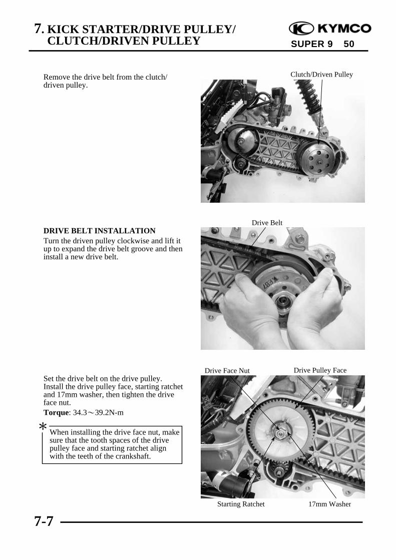
7. KICK STARTER/DRIVE PULLEY/CLUTCH/DRIVEN PULLEY
7-7
SUPER 9 50
Remove the drive belt from the clutch/driven pulley.
DRIVE BELT INSTALLATIONTurn the driven pulley clockwise and lift itup to expand the drive belt groove and theninstall a new drive belt.
Set the drive belt on the drive pulley.Install the drive pulley face, starting ratchetand 17mm washer, then tighten the driveface nut.Torque: 34.3~39.2N-m
Clutch/Driven Pulley
Drive Belt
Drive Pulley Face
17mm WasherStarting Ratchet
Drive Face Nut
When installing the drive face nut, makesure that the tooth spaces of the drivepulley face and starting ratchet alignwith the teeth of the crankshaft.
*
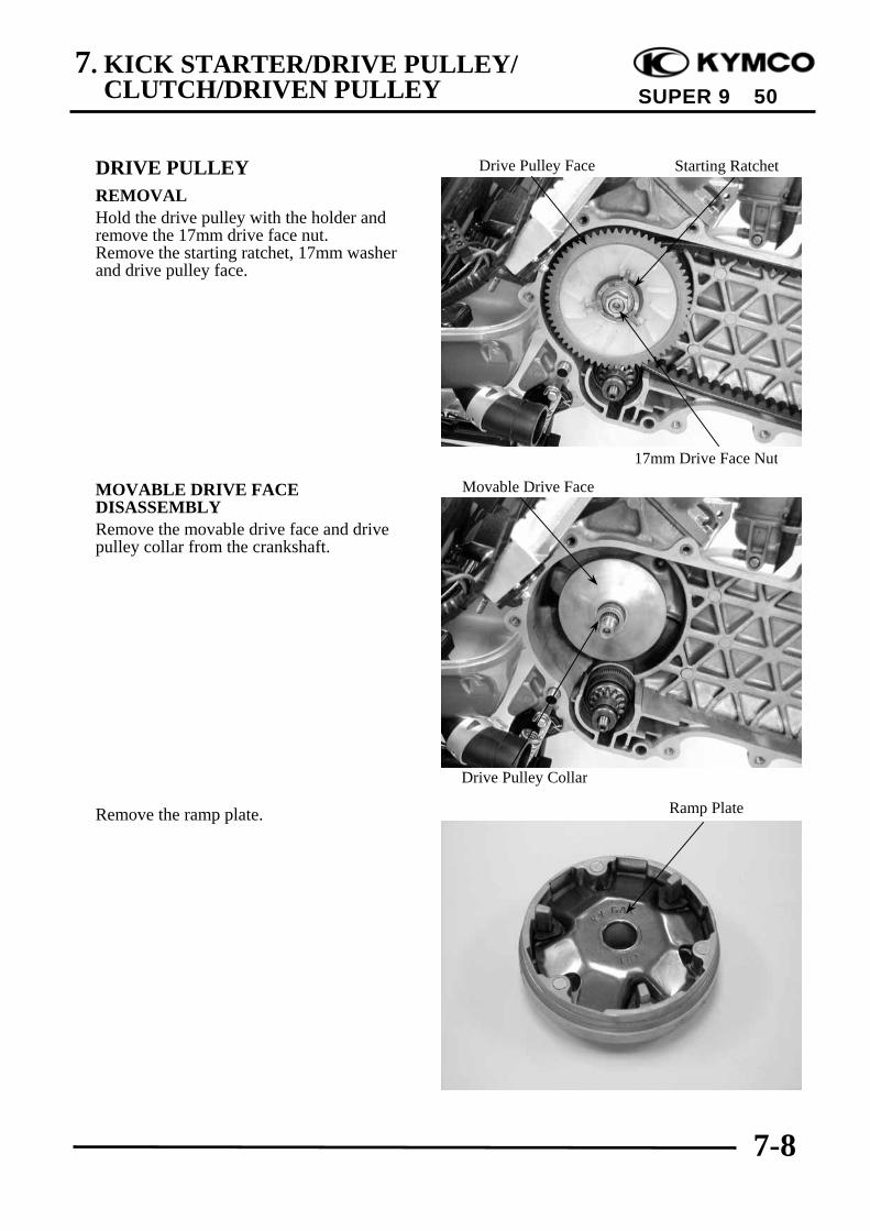
7. KICK STARTER/DRIVE PULLEY/CLUTCH/DRIVEN PULLEY
7-8
SUPER 9 50
DRIVE PULLEYREMOVALHold the drive pulley with the holder andremove the 17mm drive face nut.Remove the starting ratchet, 17mm washerand drive pulley face.
MOVABLE DRIVE FACEDISASSEMBLYRemove the movable drive face and drivepulley collar from the crankshaft.
Remove the ramp plate.
Movable Drive Face
Ramp Plate
Drive Pulley Collar
17mm Drive Face Nut
Starting RatchetDrive Pulley Face
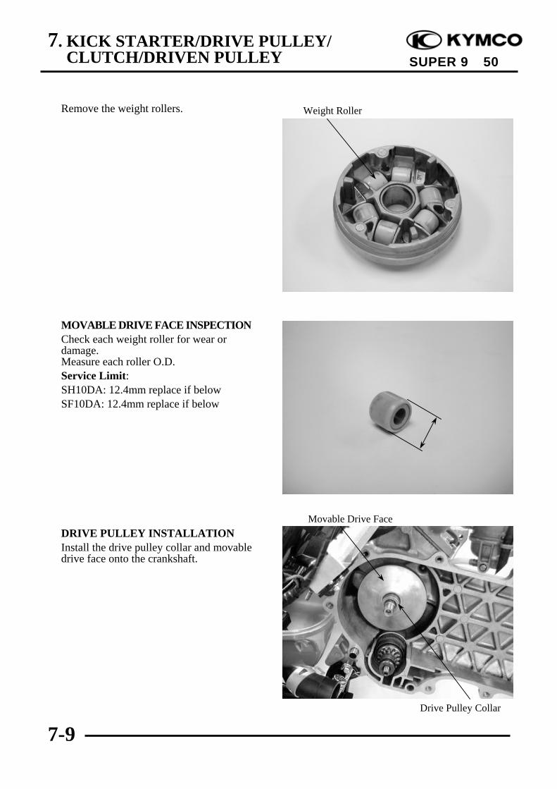
7. KICK STARTER/DRIVE PULLEY/CLUTCH/DRIVEN PULLEY
7-9
SUPER 9 50
Remove the weight rollers.
MOVABLE DRIVE FACE INSPECTIONCheck each weight roller for wear ordamage.Measure each roller O.D.Service Limit:SH10DA: 12.4mm replace if belowSF10DA: 12.4mm replace if below
DRIVE PULLEY INSTALLATIONInstall the drive pulley collar and movabledrive face onto the crankshaft.
Weight Roller
Movable Drive Face
Drive Pulley Collar

7. KICK STARTER/DRIVE PULLEY/CLUTCH/DRIVEN PULLEY
7-10
SUPER 9 50
Install the drive belt on the crankshaft.Install the drive face, starting ratchet andwasher, then tighten the 17mm drive facenut.Torque: 34.3~39.2N-m
STARTER PINIONREMOVALRemove the left crankcase cover. ( 7-2)Remove the drive pulley. ( 7-6)Remove the starter pinion.
INSPECTIONInspect the starter pinion seat for wear.Inspect the starter pinion for smoothoperation.Inspect the starter pinion shaft forcing partsfor wear and damage.
INSTALLATIONApply a small amount of grease to thestarter pinion teeth.Install the starter pinion in the reverse orderof removal.
Keep grease or oil off the drive belt anddrive pulley faces.
*
Drive Face Nut Starting Ratchet
Drive Pulley Face
Starter PinionShaft Forcing Parts
Starter Pinion
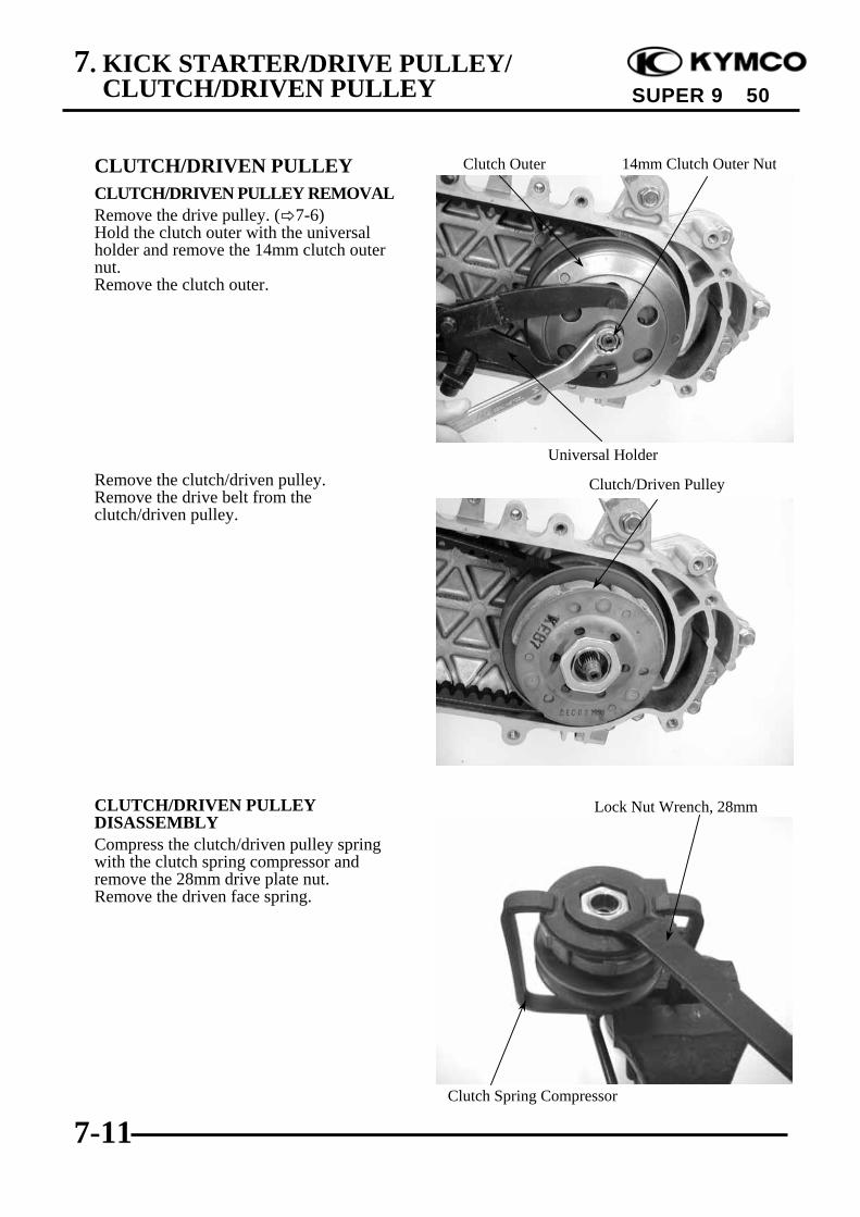
7. KICK STARTER/DRIVE PULLEY/CLUTCH/DRIVEN PULLEY
7-11
SUPER 9 50
CLUTCH/DRIVEN PULLEYCLUTCH/DRIVEN PULLEY REMOVALRemove the drive pulley. ( 7-6)Hold the clutch outer with the universalholder and remove the 14mm clutch outernut.Remove the clutch outer.
Remove the clutch/driven pulley.Remove the drive belt from theclutch/driven pulley.
CLUTCH/DRIVEN PULLEYDISASSEMBLYCompress the clutch/driven pulley springwith the clutch spring compressor andremove the 28mm drive plate nut.Remove the driven face spring.
Clutch/Driven Pulley
Universal Holder
Clutch Outer 14mm Clutch Outer Nut
Clutch Spring Compressor
Lock Nut Wrench, 28mm
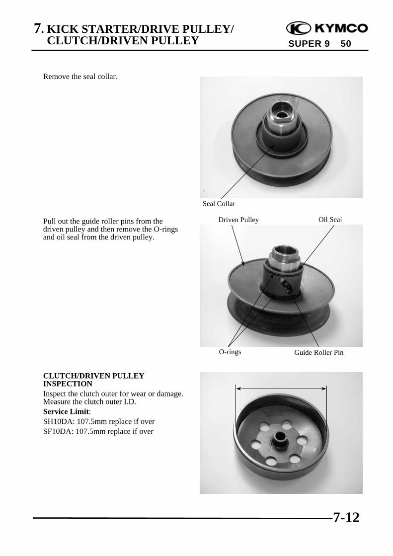
7. KICK STARTER/DRIVE PULLEY/CLUTCH/DRIVEN PULLEY
7-12
SUPER 9 50
Remove the seal collar.
Pull out the guide roller pins from thedriven pulley and then remove the O-ringsand oil seal from the driven pulley.
CLUTCH/DRIVEN PULLEYINSPECTIONInspect the clutch outer for wear or damage.Measure the clutch outer I.D.Service Limit:SH10DA: 107.5mm replace if overSF10DA: 107.5mm replace if over
Seal Collar
Oil Seal
O-rings Guide Roller Pin
Driven Pulley
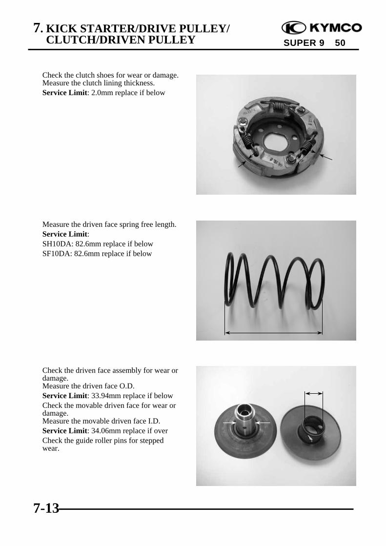
7. KICK STARTER/DRIVE PULLEY/CLUTCH/DRIVEN PULLEY
7-13
SUPER 9 50
Check the clutch shoes for wear or damage.Measure the clutch lining thickness.Service Limit: 2.0mm replace if below
Measure the driven face spring free length.Service Limit:SH10DA: 82.6mm replace if belowSF10DA: 82.6mm replace if below
Check the driven face assembly for wear ordamage.Measure the driven face O.D.Service Limit: 33.94mm replace if belowCheck the movable driven face for wear ordamage.Measure the movable driven face I.D.Service Limit: 34.06mm replace if overCheck the guide roller pins for steppedwear.
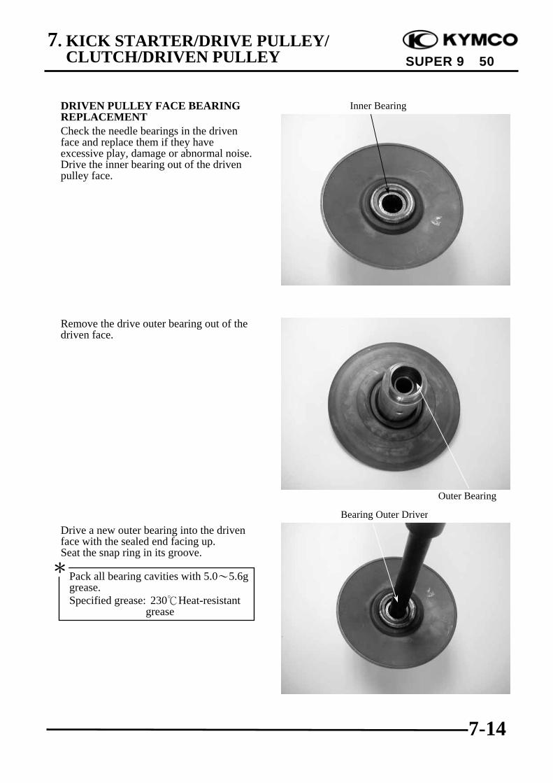
7. KICK STARTER/DRIVE PULLEY/CLUTCH/DRIVEN PULLEY
7-14
SUPER 9 50
DRIVEN PULLEY FACE BEARINGREPLACEMENTCheck the needle bearings in the drivenface and replace them if they haveexcessive play, damage or abnormal noise.Drive the inner bearing out of the drivenpulley face.
Remove the drive outer bearing out of thedriven face.
Drive a new outer bearing into the drivenface with the sealed end facing up.Seat the snap ring in its groove.
Bearing Outer Driver
Inner Bearing
Outer Bearing
Pack all bearing cavities with 5.0~5.6ggrease.Specified grease: 230Heat-resistant
grease
*
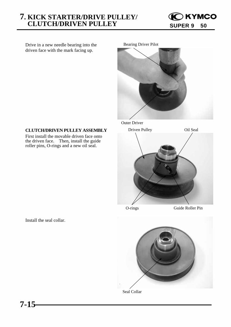
7. KICK STARTER/DRIVE PULLEY/CLUTCH/DRIVEN PULLEY
7-15
SUPER 9 50
Drive in a new needle bearing into thedriven face with the mark facing up.
CLUTCH/DRIVEN PULLEY ASSEMBLYFirst install the movable driven face ontothe driven face. Then, install the guideroller pins, O-rings and a new oil seal.
Install the seal collar.
Seal Collar
Oil Seal
O-rings Guide Roller Pin
Driven Pulley
Bearing Driver Pilot
Outer Driver

7. KICK STARTER/DRIVE PULLEY/CLUTCH/DRIVEN PULLEY
7-16
SUPER 9 50
Set the driven pulley, driven face springand clutch assembly onto the clutch springcompressor. Compress the tool and installthe 28mm drive plate nut.Tighten the 28mm nut to the specifiedtorque.Torque: 49.0~58.8N-m
CLUTCH/DRIVEN PULLEYINSTALLATIONInstall the drive belt on the clutch/drivenpulley and then install the clutch/drivenpulley onto the drive shaft.
Install the clutch outer.Hold the clutch outer with the universalholder.Install and tighten the 10mm clutch outernut.Torque: 34.3~44.1N-mInstall the left crankcase cover. ( 7-5)
Universal Holder
Clutch Outer
Clutch/Driven Pulley
8. FINAL REDUCTION
8-0
SUPER 9 50
8 __________________________________________________________________________________
__________________________________________________________________________________
__________________________________________________________________________________
__________________________________________________________________________________
__________________________________________________________________________________
FINAL REDUCTION__________________________________________________________________________________
SERVICE INFORMATION ................................................................ 8-1TROUBLESHOOTING ....................................................................... 8-1FINAL REDUCTION DISASSEMBLY ............................................. 8-2FINAL REDUCTION INSPECTION.................................................. 8-2FINAL REDUCTION ASSEMBLY.................................................... 8-5
8
8. FINAL REDUCTION
8-1
SUPER 9 50
SERVICE INFORMATIONSpecified Oil: SAE90#At disassembly: 0.12 literAt change: 0.1 liter
SPECIAL TOOLSBearing remover set, 12mmBearing remover set, 15mmCrankcase assembly collarCrankcase assembly shaftBearing outer driver, 37x40mmBearing outer driver, 32x35mmBearing driver pilot, 17mmBearing driver pilot, 15mmBearing driver pilot, 12mmBearing outer driver handle A
TROUBLESHOOTINGEngine starts but motorcycle won‘t move• Damaged transmission• Seized or burnt transmission
Abnormal noise• Worn, seized or chipped gears• Worn bearing
Oil leaks• Oil level too high• Worn or damaged oil seal
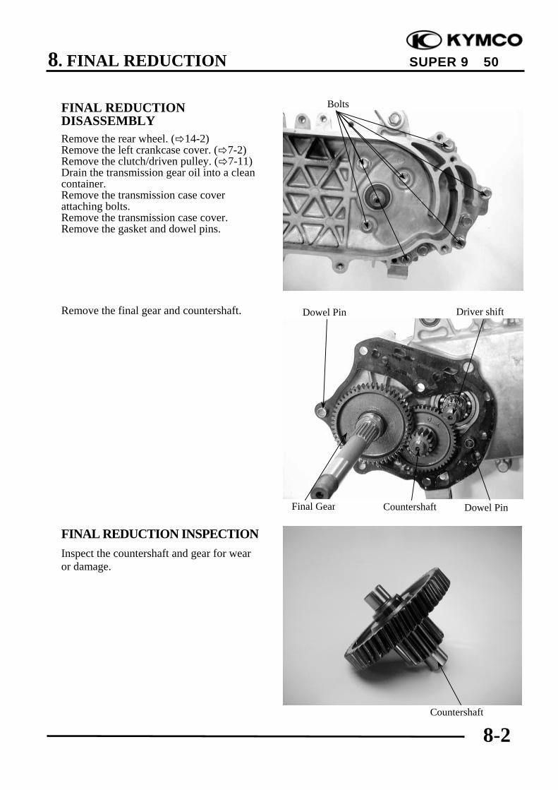
8. FINAL REDUCTION
8-2
SUPER 9 50
FINAL REDUCTIONDISASSEMBLYRemove the rear wheel. ( 14-2)Remove the left crankcase cover. ( 7-2)Remove the clutch/driven pulley. ( 7-11)Drain the transmission gear oil into a cleancontainer.Remove the transmission case coverattaching bolts.Remove the transmission case cover.Remove the gasket and dowel pins.
Remove the final gear and countershaft.
FINAL REDUCTION INSPECTIONInspect the countershaft and gear for wearor damage.
Dowel Pin
Final Gear
Countershaft
Dowel PinCountershaft
Driver shift
Bolts

8. FINAL REDUCTION
8-3
SUPER 9 50
Inspect the final gear and final shaft forwear, damage or seizure.
Check the left crankcase bearings forexcessive play and inspect the oil seal forwear or damage.
Inspect the drive shaft and gear for wear ordamage.Check the transmission case cover bearingsfor excessive play and inspect the finalshaft bearing oil seal for wear or damage.
Do not remove the transmission casecover except for necessary part replace-ment. When replacing the drive shaft,also replace the bearing and oil seal.
*
Final Shaft BearingFinal Shaft
Drive Shaft Bearing
Countershaft Bearing
Oil SealCountershaft BearingDrive Shaft Bearing
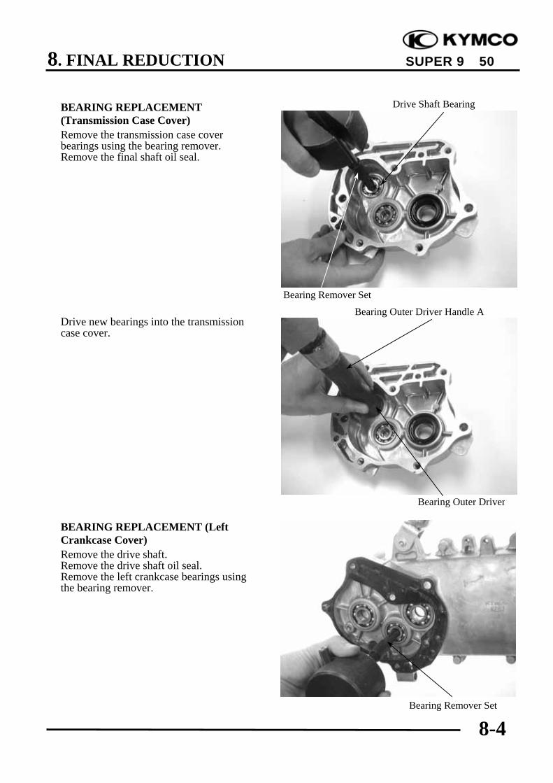
8. FINAL REDUCTION
8-4
SUPER 9 50
BEARING REPLACEMENT(Transmission Case Cover)Remove the transmission case coverbearings using the bearing remover.Remove the final shaft oil seal.
Drive new bearings into the transmissioncase cover.
BEARING REPLACEMENT (LeftCrankcase Cover)Remove the drive shaft.Remove the drive shaft oil seal.Remove the left crankcase bearings usingthe bearing remover.
Drive Shaft Bearing
Bearing Outer Driver
Bearing Remover Set
Bearing Remover Set
Bearing Outer Driver Handle A

8. FINAL REDUCTION
8-5
SUPER 9 50
Drive new bearings into the left crankcase.Install a new drive shaft oil seal.
FINAL REDUCTION ASSEMBLYInstall the drive shaft into the leftcrankcase.
Install the countershaft gear into the leftcrankcase.
Drive Shaft
Bearing Outer Driver
Countershaft Gear

8. FINAL REDUCTION
8-6
SUPER 9 50
Install the final gear and final shaft into theleft crankcase.Install the dowel pins and a new gasket.
Install the transmission case cover.
Install and tighten the transmission casecover bolts.Install the clutch/driven pulley. ( 7-15)Install other removed parts in the reverseorder of removal.
Final Shaft
Transmission Case Cover
Bolts
Dowel Pins

8. FINAL REDUCTION
8-7
SUPER 9 50
After installation, fill the transmission casewith the specified oil.
Specified Gear Oil: SAE90#Oil Capacity: at disassembly: 0.12 liter
at change: 0.1 literInstall and tighten the oil check bolt.Torque: 9.8~14.7N-mStart the engine and check for oil leaks.Check the oil level from the oil check bolthole and add the specified oil to the properlevel if the oil level is low.
• Place the motorcycle on its main standon level ground.
• Check the sealing washer for wear ordamage.
*
Drain Bolt Oil Check Bolt Hole/Filler
9. A.C. GENERATOR
9-0
SUPER 9 50
9 __________________________________________________________________________________
__________________________________________________________________________________
__________________________________________________________________________________
__________________________________________________________________________________
__________________________________________________________________________________
A.C. GENERATOR__________________________________________________________________________________
SERVICE INFORMATION ................................................................ 9-1A.C. GENERATOR REMOVAL......................................................... 9-2A.C. GENERATOR INSTALLATION ............................................... 9-5
9

9. A.C. GENERATOR
9-1
SUPER 9 50
SERVICE INFORMATION
GENERAL INSTRUCTIONS• All A.C. generator maintenance and inspection can be made with the engine installed.• Refer to Section 15 for A.C. generator inspection.
TORQUE VALUEFlywheel nut : 34.3~39.2N-m
SPECIAL TOOLSFlywheel pullerUniversal holder

9. A.C. GENERATOR
9-2
SUPER 9 50
〈SH10DA〉A.C. GENERATOR REMOVALDisconnect the water hoses from the rightcrankcase cover.Remove the three bolts attaching the rightcrankcase cover and the cover.
Hold the flywheel with an universal holderand then remove the flywheel nut.
Bolts
Universal Holder

9. A.C. GENERATOR
9-3
SUPER 9 50
〈SF10DA〉A.C. GENERATOR REMOVALRemove the three bolts attaching the fancover to remove the fan cover.
Remove the cooling fan by removing thefour bolts.
Hold the flywheel with an universal holderand then remove the flywheel nut.
Fan Cover
Bolts
Bolt
Nut
Universal Holder
Cooling Fan
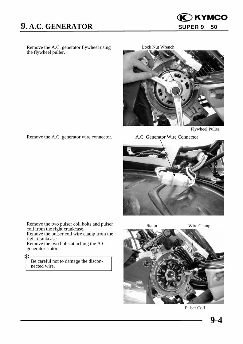
9. A.C. GENERATOR
9-4
SUPER 9 50
Remove the A.C. generator flywheel usingthe flywheel puller.
Remove the A.C. generator wire connector.
Remove the two pulser coil bolts and pulsercoil from the right crankcase.Remove the pulser coil wire clamp from theright crankcase.Remove the two bolts attaching the A.C.generator stator.
Lock Nut Wrench
A.C. Generator Wire Connector
Stator
Flywheel Puller
Pulser Coil
Wire Clamp
Be careful not to damage the discon-nected wire.
*

9. A.C. GENERATOR
9-5
SUPER 9 50
A.C. GENERATOR INSTALLATIONInstall the A.C. generator stator and pulsercoil wire clamp onto the right crankcase,and then install the pulser coil.Connect the A.C. generator wire connector.
Clean the taper hole in the flywheel off anyburrs and dirt.Install the woodruff key in the crankshaftkeyway.
Install the flywheel onto the crankshaft withthe flywheel groove aligned with thecrankshaft woodruff key.Hold the flywheel with the universal holderand install the flywheel flange nut.Torque: 34.3~39.2N-mStart the engine and check the ignitiontiming. ( 3-7)Install other removed parts in the reserveorder of removal.
A.C. Generator Wire Connector
Woodruff Key
Universal Holder

10. CRANKCASE/CRANKSHAFT
10-0
SUPER 9 50
10 __________________________________________________________________________________
__________________________________________________________________________________
__________________________________________________________________________________
__________________________________________________________________________________
__________________________________________________________________________________
CRANKCASE/CRANKSHAFT__________________________________________________________________________________
SERVICE INFORMATION ................................................................ 10-1TROUBLESHOOTING ....................................................................... 10-1CRANKCASE SEPARATION............................................................ 10-2CRANKSHAFT REMOVAL............................................................... 10-2CRANKSHAFT INSPECTION ........................................................... 10-3CRANKSHAFT INSTALLATION ..................................................... 10-4CRANKCASE ASSEMBLY................................................................ 10-6
10

10. CRANKCASE/CRANKSHAFT
10-1
SUPER 9 50
SERVICE INFORMATION
GENERAL INSTRUCTIONS• This section covers crankcase separation to service the crankshaft.• The following parts must be removed before separating the crankcase.
Engine ( Section 5) Driven pulley ( Section 7)Carburetor ( Section 12) A.C. generator ( Section9)Oil pump ( Section 4) Cylinder head/cylinder ( Section 6)Reed valve ( Section 12)
• When the left crankcase must be replaced, remove the following part in addition to the above.Final reduction removal
• Special tools must be used for crankshaft and crankcase assembly. When separating thecrankcase, the bearing will remain in the crankcase and it should be removed. When,assembling, drive a new bearing into the crankcase and install a new oil seal.
SPECIFICATIONS Standard (mm) Service Limit (mm)
Item SH10DA SF10DA SH10DA SF10DAConnecting rod big end sideclearance ⎯ 0.60
Connecting rod big end radialclearance ⎯ 0.04
Crankshaft runout A/B ⎯ 0.15/0.10
SPECIAL TOOLSCrankcase puller Bearing outer driver handle AUniversal bearing puller Bearing outer driver, 42x47mmCrankcase assembly collar Bearing driver pilot, 20mmCrankcase assembly tool Bearing outer driver, 37x40mm
Bearing driver pilot, 17mm
TROUBLESHOOTINGAbnormal engine noise• Excessive crank journal bearing play• Excessive crankpin bearing play• Excessive transmission bearing play
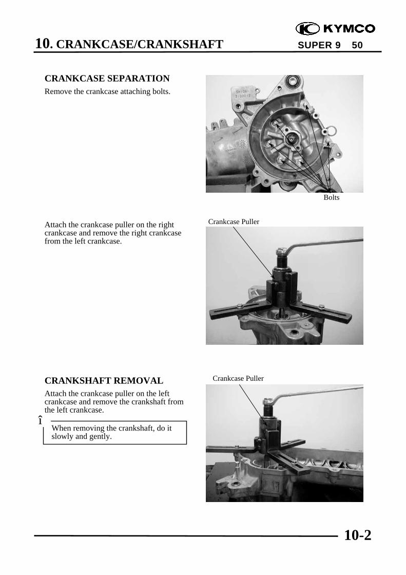
10. CRANKCASE/CRANKSHAFT
10-2
SUPER 9 50
CRANKCASE SEPARATIONRemove the crankcase attaching bolts.
Attach the crankcase puller on the rightcrankcase and remove the right crankcasefrom the left crankcase.
CRANKSHAFT REMOVALAttach the crankcase puller on the leftcrankcase and remove the crankshaft fromthe left crankcase.
Crankcase Puller
Crankcase Puller
Bolts
When removing the crankshaft, do itslowly and gently.
*

10. CRANKCASE/CRANKSHAFT
10-3
SUPER 9 50
Remove the remaining bearing on thecrankshaft side using the universal bearingpuller.
CRANKSHAFT INSPECTIONMeasure the connecting rod big end sideclearance.Service Limit: 0.6mm replace if over
Measure the connecting rod big end radialclearance at two points in the X and Ydirections.Service Limit: 0.04mm replace if over
When separating the crankcase, the oilseals must be removed. Replace the oilseals with new ones.
*
Universal Bearing Puller

10. CRANKCASE/CRANKSHAFT
10-4
SUPER 9 50
Measure the crankshaft runout.
Service LimitA B
0.150mmreplace if over
0.100mmreplace if over
Check the crankshaft bearings for excessiveplay.The bearings must be replaced if they arenoisy or have excessive play.
CRANKSHAFT INSTALLATIONWash the crankshaft in cleaning solvent andthen check for cracks or other faults.
Axial
Play
Play
Radial
• After check, apply clean engine oil toall moving and sliding parts.
• Remove all gasket material from thecrankcase mating surfaces. Dressany roughness or irregularities with anoil stone.
*
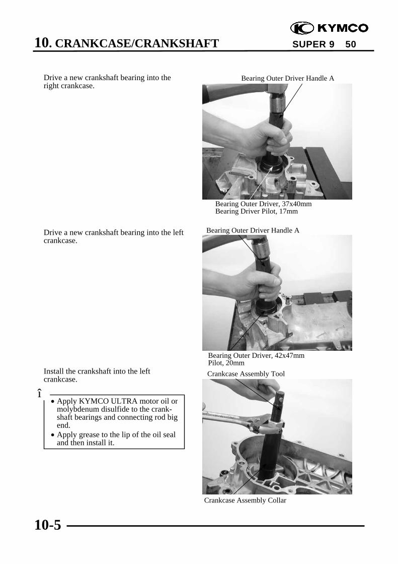
10. CRANKCASE/CRANKSHAFT
10-5
SUPER 9 50
Drive a new crankshaft bearing into theright crankcase.
Drive a new crankshaft bearing into the leftcrankcase.
Install the crankshaft into the leftcrankcase.
Bearing Outer Driver Handle A
Bearing Outer Driver Handle A
Bearing Outer Driver, 37x40mmBearing Driver Pilot, 17mm
Bearing Outer Driver, 42x47mmPilot, 20mmCrankcase Assembly Tool
Crankcase Assembly Collar
• Apply KYMCO ULTRA motor oil ormolybdenum disulfide to the crank-shaft bearings and connecting rod bigend.
• Apply grease to the lip of the oil sealand then install it.
*

10. CRANKCASE/CRANKSHAFT
10-6
SUPER 9 50
CRANKCASE ASSEMBLYInstall the dowel pins and a new gasket tothe crankcase mating surface.
Assemble the crankcase halves.
The distance between the right crankcaseoil seal and crankcase surface is about12.5±0.5 mm.
Dowel Pins
Crankcase Assembly Tool
Crankcase Oil Seal
When installing the oil seal, be carefulto press it with even force.
*
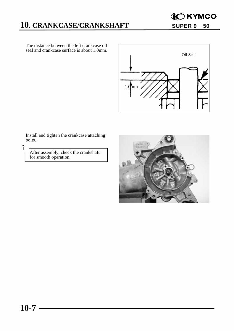
10. CRANKCASE/CRANKSHAFT
10-7
SUPER 9 50
The distance between the left crankcase oilseal and crankcase surface is about 1.0mm.
Install and tighten the crankcase attachingbolts.
After assembly, check the crankshaftfor smooth operation.
*
Oil Seal
1.0mm

11. COOLING SYSTEM
11-0
SUPER 9 50
11 __________________________________________________________________________________
__________________________________________________________________________________
__________________________________________________________________________________
__________________________________________________________________________________
__________________________________________________________________________________
COOLING SYSTEM__________________________________________________________________________________
SERVICE INFORMATION------------------------------------------------ 11- 1TROUBLESHOOTING----------------------------------------------------- 11- 1RADIATOR ------------------------------------------------------------------ 11- 3WATER PUMP -------------------------------------------------------------- 11- 6THERMOSENSOR---------------------------------------------------------- 11-12THERMOSTAT-------------------------------------------------------------- 11-13
11
11. COOLING SYSTEM
11-1
SUPER 9 50
SERVICE INFORMATION
GENERAL INSTRUCTIONS• The water pump must be serviced after removing the engine. Other cooling system service can
be done with the engine installed in the frame.• The engine must be cool before servicing the cooling system.
When the coolant temperature is over 100, never remove the radiator cap to release thepressure because the boiling coolant may cause danger.
• Avoid spilling coolant on painted surfaces because the coolant will corrode the painted surfaces.Wash off any spilled coolant with fresh water as soon as possible.
• After servicing the system, check for leaks with a cooling system tester.
SPECIAL TOOLMechanical seal driver
TORQUE VALUESWater pump impeller 9.8~13.72N-mWater pump cover bolt 7.84~11.76N-m
TROUBLESHOOTINGEngine temperature too high Coolant leaks• Faulty temperature gauge or thermosensor • Faulty pump mechanical (water) seal• Faulty radiator cap • Deteriorated O-rings• Faulty thermostat • Damaged or deteriorated water hoses• Insufficient coolant• Passages blocked in hoses or water jacket• Clogged radiator fins• Passages blocked in radiator• Faulty water pump
Temperature gauge pointer does not registerthe correct coolant temperature• Faulty temperature gauge or thermosensor• Faulty thermostat

11. COOLING SYSTEM
11-2
SUPER 9 50
SPECIFICATIONS Begins to open 80±2
Thermostat temperature Full-open 90 Valve lift 3.5~4.5mm
Coolant capacity Total system 1165cc Radiator: 825ccReserve tank: 340cc
COOLANT GRAVITYTemp.
Coolantconcentration
0 5 10 15 20 25 30 35 40 45 50
5% 1.009 1.009 1.008 1.008 1.007 1.006 1.005 1.003 1.001 0.009 0.99710% 1.018 1.107 1.017 1.016 1.015 1.014 0.013 1.011 1.009 1.007 1.00515% 1.028 1.027 1.026 1.025 1.024 1.022 1.020 1.018 1.016 1.014 1.01220% 1.036 1.035 1.034 1.033 1.031 1.029 1.027 1.025 1.023 1.021 1.01925% 1.045 1.044 1.043 1.042 1.040 1.038 1.036 1.034 1.031 1.028 1.02530% 1.053 1.051 1.051 1.049 1.047 1.045 1.043 1.041 1.038 1.035 1.03235% 1.063 1.062 1.060 1.058 1.056 1.054 1.052 1.049 1.046 1.043 1.04040% 1.072 1.070 1.068 1.066 1.064 1.062 1.059 1.056 1.053 1.050 1.04745% 1.080 1.078 1.076 1.074 1.072 1.069 1.056 1.063 1.062 1.057 1.05450% 1.086 1.084 1.082 1.080 1.077 1.074 1.071 1.068 1.065 1.062 1.05955% 1.095 1.093 1.091 1.088 1.085 1.082 1.079 1.076 1.073 1.070 1.06760% 1.100 1.098 1.095 1.092 1.089 1.086 1.083 1.080 1.077 1.074 1.071
COOLANT MIXTURE (WITH ANTI-RUST AND ANTI-FREEZING EFFECTS)Freezing Point Mixing Rate KYMCO SIGMA Coolant Concentrate Distilled Water
-9 20% -15 30% 360cc 825cc -25 40% -37 50% -44.5 55%
Cautions for Using Coolant:• Use coolant of specified mixing rate. (The
mixing rate of 360cc KYMCO SIGMAcoolant concentrate + 825cc distilledwater is 30%.)
• Do not mix coolant concentrate ofdifferent brands.
• Do not drink the coolant which ispoisonous.
• The freezing point of coolant mixtureshall be 5lower than the freezing pointof the riding area.

11. COOLING SYSTEM
11-3
SUPER 9 50
RADIATORRADIATOR INSPECTIONRemove the front upper cover. ( 2-3)Remove the front lower cover. ( 2-3)
Inspect the radiator soldered joints andseams for leaks.Blow dirt out from between core fins withcompressed air. If insects, etc., areclogging the radiator, wash them off.Carefully straighten any bent fins.
RADIATOR REMOVALDrain the coolant. ( 3-10)Loosen the hose band and disconnect theupper and lower hose from connect theradiator and reserve tank.
Upper Hose
Reserve Tank
Front Upper Cover
Front Lower Cover
Radiator
Lower Hose
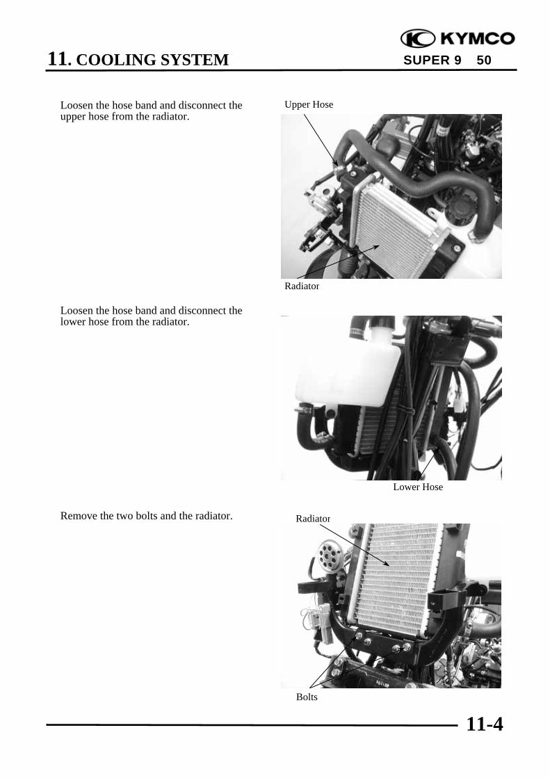
11. COOLING SYSTEM
11-4
SUPER 9 50
Loosen the hose band and disconnect theupper hose from the radiator.
Loosen the hose band and disconnect thelower hose from the radiator.
Remove the two bolts and the radiator.
Radiator
Upper Hose
Lower Hose
Radiator
Bolts

11. COOLING SYSTEM
11-5
SUPER 9 50
RADIATOR BRACKET REMOVAL/INSTALLATIONRemove the two nuts to remove the radiatorbracket.The installation sequence is the reverse ofremoval.
RADIATOR INSTALLATIONInstall the radiator on the radiator bracketwith the two bolts.
Connect the upper and lower hoses andsecure them with hose bands.
Nuts
Radiator
Radiator Bracket
Lower Hoses
Bolts
Upper Hoses

11. COOLING SYSTEM
11-6
SUPER 9 50
Reinstall the upper and lower hoses, makesure the bands are secured.
Fill the reserve tank with coolant. ( 3-10)Check for coolant leaks.Install the front upper and lower cover.
WATER PUMPMECHANICAL SEAL (WATER SEAL)INSPECTIONInspect the telltale hole for signs ofmechanical seal coolant leakage.If the mechanical seal is leaking, removethe right crankcase cover and replace themechanical seal.
.
Air Duct
Right Crankcase Cover
Upper Hose
Telltale Hole
Water Pump
Lower HoseReserve Tank
Reserve Tank

11. COOLING SYSTEM
11-7
SUPER 9 50
WATER PUMP/IMPELLERREMOVALRemove the engine from the frame. ( 5-2)
Remove the three bolts and the water pumpcover, gasket and two dowel pins.
Remove the water pump impeller. Impeller
Water Pump Cover
Bolts
The impeller has left hand threads.*

11. COOLING SYSTEM
11-8
SUPER 9 50
Bolts
Water Pump Assembly
Water Hose
Bolts
Water Pump Assembly
Inspect the mechanical (water) seal and sealwasher for wear or damage.
WATER PUMP SHAFT REMOVALDisconnect the water hose from the rightcrankcase cover.Remove the two timing cap bolts and thetiming cap.Remove the three bolts attaching the waterpump assembly.Remove the water pump assembly anddowel pins.
Remove the water pump shaft from thewater pump assembly.
Mechanical Seal
Water Pump Shaft
Impeller
Seal Washer (Porcelain)
The mechanical seal and seal washermust be replace as a set.
*
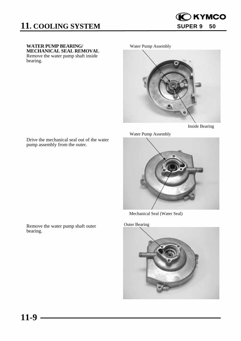
11. COOLING SYSTEM
11-9
SUPER 9 50
Water Pump Assembly
WATER PUMP BEARING/MECHANICAL SEAL REMOVALRemove the water pump shaft insidebearing.
Drive the mechanical seal out of the waterpump assembly from the outer.
Remove the water pump shaft outerbearing.
Water Pump Assembly
Mechanical Seal (Water Seal)
Outer Bearing
Inside Bearing
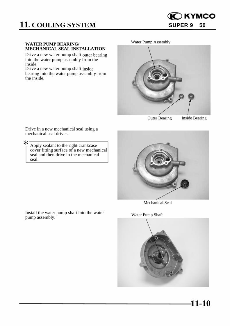
11. COOLING SYSTEM
11-10
SUPER 9 50
WATER PUMP BEARING/MECHANICAL SEAL INSTALLATIONDrive a new water pump shaft outer bearinginto the water pump assembly from theinside.Drive a new water pump shaft insidebearing into the water pump assembly fromthe inside.
Drive in a new mechanical seal using amechanical seal driver.
Install the water pump shaft into the waterpump assembly.
Water Pump Assembly
Water Pump Shaft
Inside Bearing
Mechanical Seal
Apply sealant to the right crankcasecover fitting surface of a new mechanicalseal and then drive in the mechanicalseal.
*
Outer Bearing
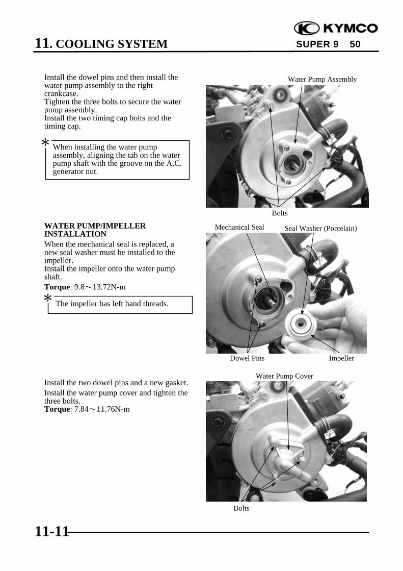
11. COOLING SYSTEM
11-11
SUPER 9 50
Install the dowel pins and then install thewater pump assembly to the rightcrankcase.Tighten the three bolts to secure the waterpump assembly.Install the two timing cap bolts and thetiming cap.
WATER PUMP/IMPELLERINSTALLATIONWhen the mechanical seal is replaced, anew seal washer must be installed to theimpeller.Install the impeller onto the water pumpshaft.Torque: 9.8~13.72N-m
Install the two dowel pins and a new gasket.Install the water pump cover and tighten thethree bolts.Torque: 7.84~11.76N-m
Water Pump Assembly
Water Pump Cover
Bolts
Mechanical Seal
Dowel Pins
Seal Washer (Porcelain)
The impeller has left hand threads.*
When installing the water pumpassembly, aligning the tab on the waterpump shaft with the groove on the A.C.generator nut.
*
Impeller
Bolts
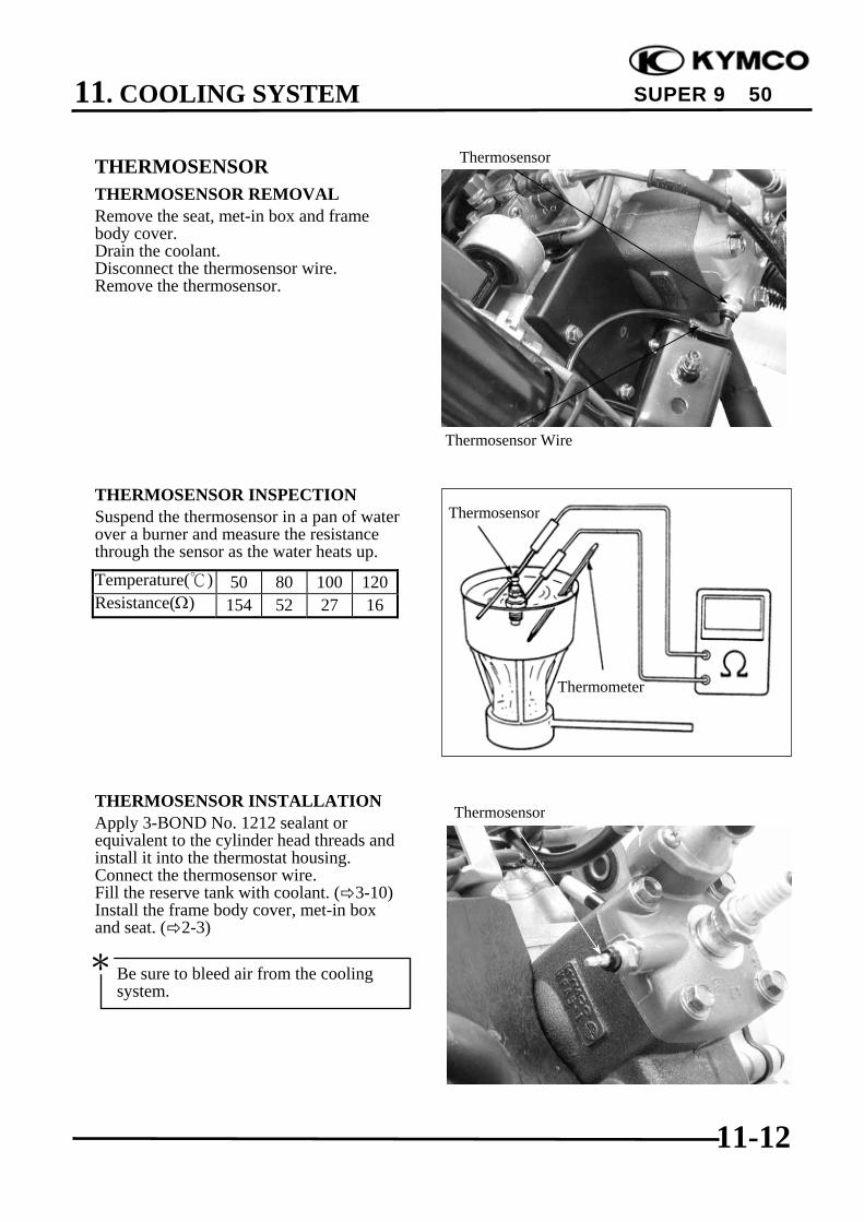
11. COOLING SYSTEM
11-12
SUPER 9 50
Thermosensor
Thermometer
THERMOSENSORTHERMOSENSOR REMOVALRemove the seat, met-in box and framebody cover.Drain the coolant.Disconnect the thermosensor wire.Remove the thermosensor.
THERMOSENSOR INSPECTIONSuspend the thermosensor in a pan of waterover a burner and measure the resistancethrough the sensor as the water heats up.Temperature() 50 80 100 120Resistance(Ω) 154 52 27 16
THERMOSENSOR INSTALLATIONApply 3-BOND No. 1212 sealant orequivalent to the cylinder head threads andinstall it into the thermostat housing.Connect the thermosensor wire.Fill the reserve tank with coolant. ( 3-10)Install the frame body cover, met-in boxand seat. ( 2-3)
Thermosensor
Thermosensor Wire
Thermosensor
Be sure to bleed air from the coolingsystem.
*

11. COOLING SYSTEM
11-13
SUPER 9 50
THERMOSTATTHERMOSTAT REMOVALRemove the seat, met-in box and framebody cover.Drain the coolant.Disconnect the water hose from thethermostat housing.
Remove the two screws and separate thethermostat housing cover .Remove the thermostat from the thermostathousing.
THERMOSTAT INSPECTIONSuspend the thermostat in a pan of waterover a burner and gradually raise the watertemperature to check its operation.Technical Data
Begins to open 80±2 Full-open 90 Valve lift 3.5~4.5mm
Thermostat Housing
Water Hose
Thermostat
Screws
Thermostat
Thermometer
• Do not let the thermostat touch the panas it will give a false reading.
• Replace the thermostat if the valvestays open at room temperature.
•Test the thermostat after it is opened forabout 5 minutes and holds thetemperature at 70.
*

11. COOLING SYSTEM
11-14
SUPER 9 50
THERMOSTAT INSTALLATIONThe installation sequence is the reverse ofremoval.Fill the cooling system with the specifiedcoolant. ( 3-10)
Thermostat Housing
12. CARBURETOR
12-0
SUPER 9 50
12 __________________________________________________________________________________
__________________________________________________________________________________
__________________________________________________________________________________
__________________________________________________________________________________
__________________________________________________________________________________
CARBURETOR__________________________________________________________________________________
SERVICE INFORMATION ................................................................ 12- 1TROUBLESHOOTING ....................................................................... 12- 1THROTTLE VALVE DISASSEMBLY .............................................. 12- 2THROTTLE VALVE INSTALLATION............................................. 12- 3CARBURETOR REMOVAL .............................................................. 12- 4AUTO BYSTARTER........................................................................... 12- 5FLOAT CHAMBER ............................................................................ 12- 7FLOAT LEVEL INSPECTION ........................................................... 12- 9CARBURETOR INSTALLATION ..................................................... 12-10AIR SCREW ADJUSTMENT ............................................................. 12-10REED VALVE ..................................................................................... 12-11
12

12. CARBURETOR
12-1
SUPER 9 50
SERVICE INFORMATION
GENERAL INSTRUCTIONS•When working with gasoline, keep away from sparks and flames..•Note the locations of O-rings when disassembling and replace them with new ones during
assembly.•All cables, fuel lines and wires must be routed and secured at correct locations.•Bleed air from the oil lines whenever they are disconnected.
SPECIFICATIONS SH10DA SF10DAVenturi dia. 14mmIdentification number PB093 PB058Float level 8.6mmMain jet(Unlimited/limited speed) #92/#78Slow jet #35Air screw opening 1¼± ½Idle speed 2000±100rpm 1900±100rpmThrottle grip free play 2~6mm
SPECIAL TOOLFloat level gauge
TROUBLESHOOTINGEngine does not start Lean mixture• No fuel in tank • Clogged fuel jets • Faulty float valve• Too much fuel getting to cylinder • Clogged fuel cap vent • Float level too low• Clogged fuel filter • Clogged fuel filter • Clogged air cleaner• Clogged air cleaner • Bent, kinked or restricted fuel line
Engine idles roughly, stalls or runs poorly Rich mixture• Incorrect idle speed • Clogged air cleaner • Faulty float valve• Ignition malfunction • Intake air leaks • Float level too high• Compression too low • Fuel contaminated • Clogged air jets• Incorrectly adjusted air screw • Faulty reed valve• Incorrect float level • Clogged fuel jets
C C

12. CARBURETOR
12-2
SUPER 9 50
THROTTLE VALVE DIS-ASSEMBLYRemove the rear carrier. ( 2-3)Remove the met-in box. ( 2-4)Loosen the carburetor cap and remove thethrottle valve.
Disconnect the throttle cable from thethrottle valve.
Remove the throttle valve spring,carburetor cap and rubber seal.
Carburetor Cap
Throttle Valve
Rubber Seal Carburetor Cap
Spring
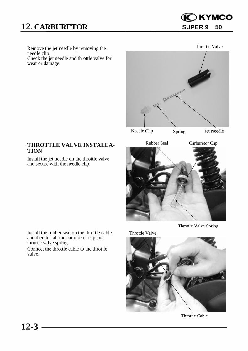
12. CARBURETOR
12-3
SUPER 9 50
Remove the jet needle by removing theneedle clip.Check the jet needle and throttle valve forwear or damage.
THROTTLE VALVE INSTALLA-TIONInstall the jet needle on the throttle valveand secure with the needle clip.
Install the rubber seal on the throttle cableand then install the carburetor cap andthrottle valve spring.Connect the throttle cable to the throttlevalve.
Carburetor Cap
Throttle Valve
Rubber Seal
Throttle Cable
Throttle Valve Spring
Throttle Valve
Jet NeedleNeedle Clip Spring

12. CARBURETOR
12-4
SUPER 9 50
Install the throttle valve by aligning thegroove in the throttle valve with the throttlestop screw.
Tighten the carburetor cap.After installation, perform the followingadjustments and inspections.• Throttle cable free play ( 3-12)• Idle speed adjustment ( 3-11)Install the met-in box.
CARBURETOR REMOVALRemove the met-in box. ( 2-3)Remove the air cleaner by removing the aircleaner band screw and attaching bolts.Disconnect the fuel tube.Loosen the drain bolt to drain fuel from thecarburetor.Disconnect the auto bystarter wireconnector.
Carburetor Cap
Drain Bolt
Throttle Cable
Throttle Stop Screw
Groove
Fuel Tube
Band
Auto Bystarter
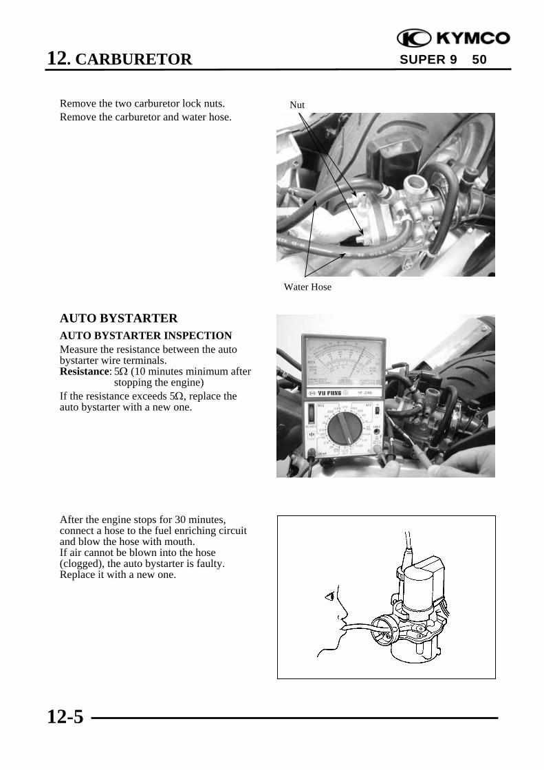
12. CARBURETOR
12-5
SUPER 9 50
Remove the two carburetor lock nuts.Remove the carburetor and water hose.
AUTO BYSTARTERAUTO BYSTARTER INSPECTIONMeasure the resistance between the autobystarter wire terminals.Resistance: 5Ω (10 minutes minimum after
stopping the engine)If the resistance exceeds 5Ω, replace theauto bystarter with a new one.
After the engine stops for 30 minutes,connect a hose to the fuel enriching circuitand blow the hose with mouth.If air cannot be blown into the hose(clogged), the auto bystarter is faulty.Replace it with a new one.
Nut
Water Hose

12. CARBURETOR
12-6
SUPER 9 50
Connect the auto bystarter yellow wire tothe battery positive (+) terminal and green/black wire to the battery negative (-)terminal and wait 5 minutes.Connect a hose to the fuel enriching circuitand blow the hose with mouth.If air can be blown into the hose, the autobystarter is faulty and replace it with a newone.
AUTO BYSTARTER REMOVALRemove the auto bystarter cover.Remove the two auto bystarter set platescrews to remove the auto bystarter.
Check the auto bystarter valve and needlefor wear or damage.Check the O-ring for wear or damage.
Auto Bystarter
Screws
O-ring
Set Plate
Bystarter ValveBystarter Needle
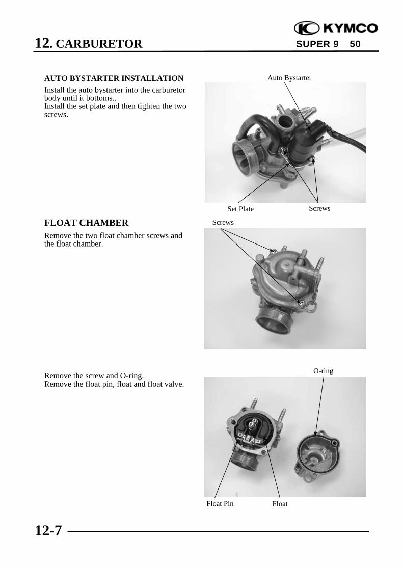
12. CARBURETOR
12-7
SUPER 9 50
AUTO BYSTARTER INSTALLATIONInstall the auto bystarter into the carburetorbody until it bottoms..Install the set plate and then tighten the twoscrews.
FLOAT CHAMBERRemove the two float chamber screws andthe float chamber.
Remove the screw and O-ring.Remove the float pin, float and float valve.
Auto Bystarter
Float
O-ring
Float Pin
Screws
ScrewsSet Plate
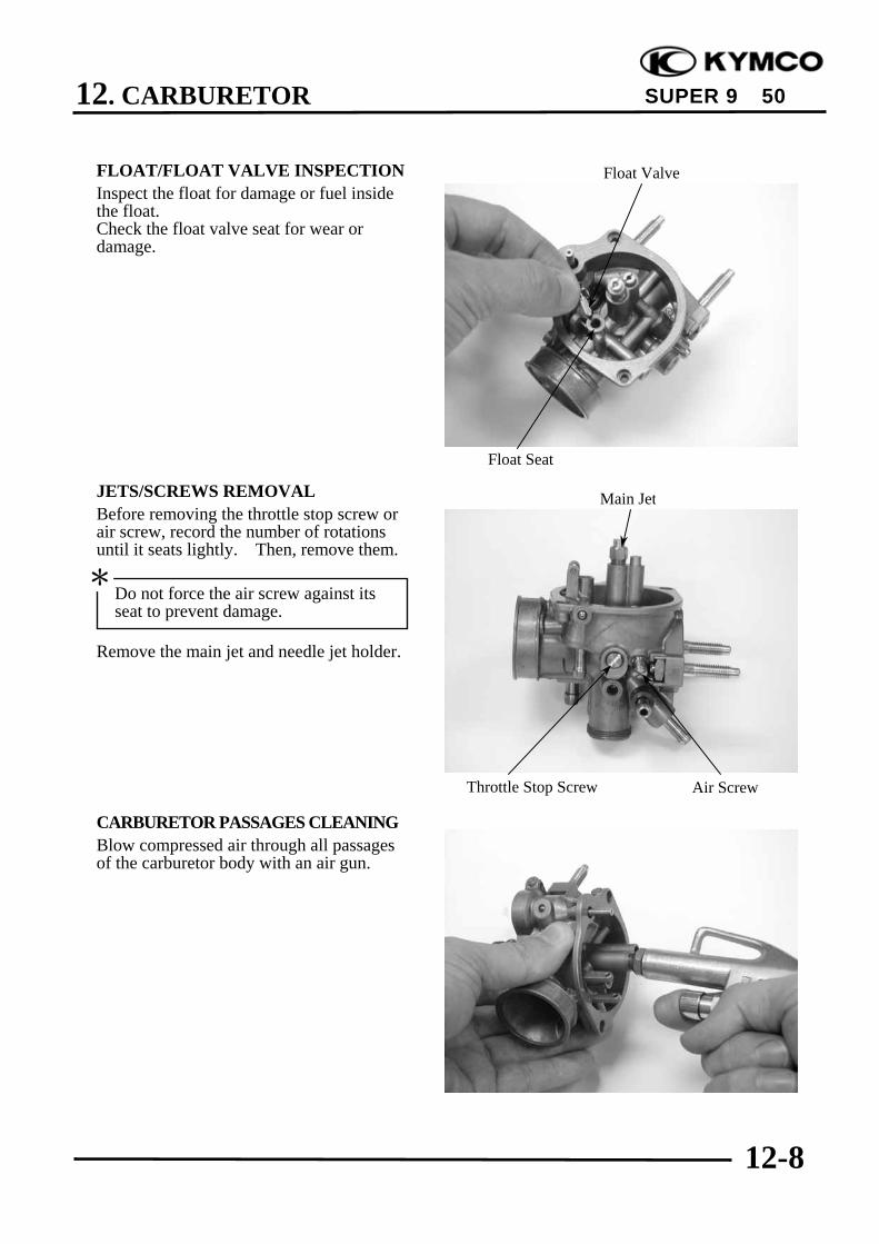
12. CARBURETOR
12-8
SUPER 9 50
FLOAT/FLOAT VALVE INSPECTIONInspect the float for damage or fuel insidethe float.Check the float valve seat for wear ordamage.
JETS/SCREWS REMOVALBefore removing the throttle stop screw orair screw, record the number of rotationsuntil it seats lightly. Then, remove them.
Remove the main jet and needle jet holder.
CARBURETOR PASSAGES CLEANINGBlow compressed air through all passagesof the carburetor body with an air gun.
Float Valve
Float Seat
Main Jet
Throttle Stop Screw Air Screw
Do not force the air screw against itsseat to prevent damage.
*

12. CARBURETOR
12-9
SUPER 9 50
FLOAT CHAMBER ASSEMBLYInstall the main jet and needle jet holder.Install the air screw and throttle stop screwaccording to the rotations recorded.
Install the float valve, float and float pin.Tighten the float screw securely.
FLOAT LEVEL INSPECTIONSlightly tilt the carburetor and measure thefloat level with the float valve justconnecting the float arm.Float Level: 8.6 mmReplace the float if the level is out of thespecified level range.Install the O-ring.Check the operation of the float and installthe float chamber.Tighten the screws.
If the air screw must be replaced, besure to perform the air screw adjustmentagain.
*
Air ScrewThrottle Stop Screw
Needle Jet holder
Float Pin
Main Jet
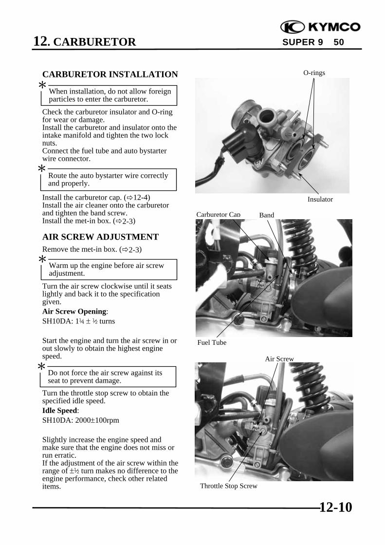
12. CARBURETOR
12-10
SUPER 9 50
CARBURETOR INSTALLATION
Check the carburetor insulator and O-ringfor wear or damage.Install the carburetor and insulator onto theintake manifold and tighten the two locknuts.Connect the fuel tube and auto bystarterwire connector.
Install the carburetor cap. ( 12-4)Install the air cleaner onto the carburetorand tighten the band screw.Install the met-in box. ( 2-3)
AIR SCREW ADJUSTMENTRemove the met-in box. ( 2-3)
Turn the air screw clockwise until it seatslightly and back it to the specificationgiven.Air Screw Opening:SH10DA: 1¼ ± ½ turns
Start the engine and turn the air screw in orout slowly to obtain the highest enginespeed.
Turn the throttle stop screw to obtain thespecified idle speed.Idle Speed:SH10DA: 2000±100rpm
Slightly increase the engine speed andmake sure that the engine does not miss orrun erratic.If the adjustment of the air screw within therange of ±½ turn makes no difference to theengine performance, check other relateditems.
When installation, do not allow foreignparticles to enter the carburetor.
*
Route the auto bystarter wire correctlyand properly.
*
Warm up the engine before air screwadjustment.
*
Do not force the air screw against itsseat to prevent damage.
*Air Screw
Throttle Stop Screw
O-rings
Insulator
Carburetor Cap
Fuel Tube
Band
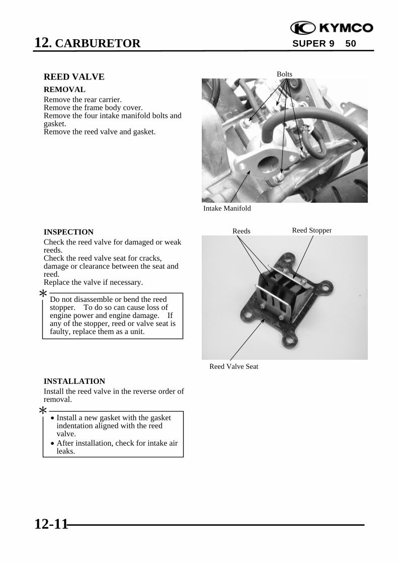
12. CARBURETOR
12-11
SUPER 9 50
REED VALVEREMOVALRemove the rear carrier.Remove the frame body cover.Remove the four intake manifold bolts andgasket.Remove the reed valve and gasket.
INSPECTIONCheck the reed valve for damaged or weakreeds.Check the reed valve seat for cracks,damage or clearance between the seat andreed.Replace the valve if necessary.
INSTALLATIONInstall the reed valve in the reverse order ofremoval.
• Install a new gasket with the gasketindentation aligned with the reedvalve.
• After installation, check for intake airleaks.
*
Bolts
Do not disassemble or bend the reedstopper. To do so can cause loss ofengine power and engine damage. Ifany of the stopper, reed or valve seat isfaulty, replace them as a unit.
*
Reeds
Intake Manifold
Reed Valve Seat
Reed Stopper

13. STEERING HANDLEBAR/FRONT WHEEL/FRONTBRAKE/FRONT SHOCK ABSORBER/FRONT FORK
13-0
SUPER 9 50
13 __________________________________________________________________________________
__________________________________________________________________________________
__________________________________________________________________________________
__________________________________________________________________________________
__________________________________________________________________________________
STEERING HANDLEBAR/FRONT WHEEL/FRONTBRAKE/FRONT SHOCK ABSORBER/FRONT FORK
__________________________________________________________________________________
SERVICE INFORMATION------------------------------------------------ 13- 1TROUBLESHOOTING----------------------------------------------------- 13- 2STEERING HANDLEBAR ------------------------------------------------ 13- 3FRONT WHEEL------------------------------------------------------------- 13- 5FRONT BRAKE ------------------------------------------------------------- 13- 8BRAKE CALIPER ---------------------------------------------------------- 13-11FRONT SHOCK ABSORBER--------------------------------------------- 13-14FRONT FORK --------------------------------------------------------------- 13-18
13

13. STEERING HANDLEBAR/FRONT WHEEL/FRONTBRAKE/FRONT SHOCK ABSORBER/FRONT FORK
13-1
SUPER 9 50
SERVICE INFORMATIONGENERAL INSTRUCTIONS• Remove the motorcycle frame covers before removing the front wheel, steering handlebar, front
shock absorber and front fork. Jack the motorcycle front wheel off the ground and be careful toprevent the motorcycle from falling down.
• During servicing, keep oil or grease off the brake pads and brake disk.
SPECIFICATIONS
Item Standard (mm) Service Limit (mm)Axle shaft runout ⎯ 0.2
Radial ⎯ 2.0Axial ⎯ 2.0
Front brake pad thickness 4.0 2.0Front shock absorber spring free length 221.5 204.3Brake disk thickness 3.8~4.2 3.0Brake disk runout ⎯ 0.30Brake master cylinder I.D. 11.0~11.043 11.055Brake master cylinder piston O.D. 10.957~10.970 10.945Brake caliper piston O.D. 25.335~25.368 25.30Brake caliper cylinder I.D. 25.400~25.45 25.485
TORQUE VALUESSteering stem lock nut 78.4~117.6N-mSteering top cone race 4.9~12.74N-mFront shock absorber bolt 19.6~24.5N-mFront axle nut 44.1~49.0N-mBrake caliper bolt 24.5~34.3N-m
SPECIAL TOOLSLock nut wrenchFront shock absorber compressorBall race removerDriver handleOuter driverBearing removerBearing remover head, 12mm
Front wheel rim runout

13. STEERING HANDLEBAR/FRONT WHEEL/FRONTBRAKE/FRONT SHOCK ABSORBER/FRONT FORK
13-2
SUPER 9 50
TROUBLESHOOTINGHard steering (heavy) Front wheel wobbling• Excessively tightened steering stem top • Bent rim
cone race • Loose front axle• Broken steering balls • Bent spoke plate• Insufficient tire pressure • Faulty tireSteers to one side or does not track straight • Improperly tightened axle nut• Uneven front shock absorbers Soft front shock absorber• Bent front fork • Weak shock springs• Bent front axle or uneven tire • Insufficient damper oilPoor brake performance Front shock absorber noise• Worn brake pads • Slider bending• Contaminated brake pad surface • Loose fork fasteners• Deformed brake disk • Lack of lubrication• Air in brake system• Deteriorated brake fluid• Worn brake master cylinder piston oil seal• Clogged brake fluid line• Unevenly worn brake caliper
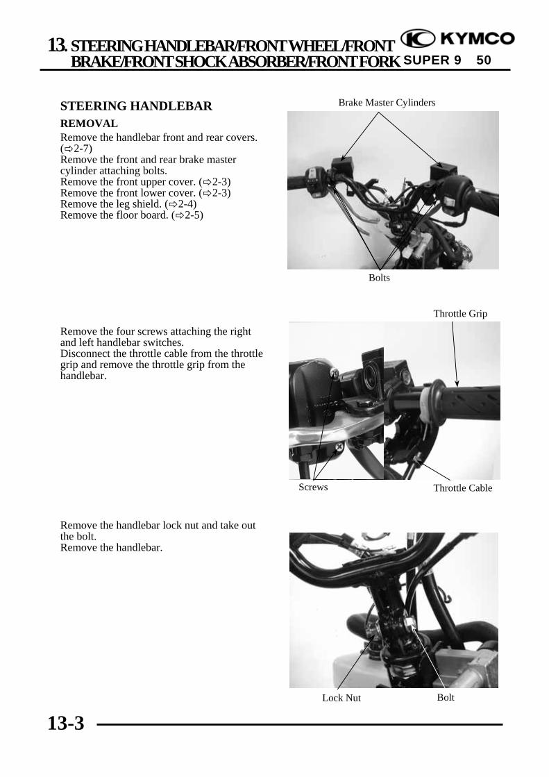
13. STEERING HANDLEBAR/FRONT WHEEL/FRONTBRAKE/FRONT SHOCK ABSORBER/FRONT FORK
13-3
SUPER 9 50
STEERING HANDLEBARREMOVALRemove the handlebar front and rear covers.( 2-7)Remove the front and rear brake mastercylinder attaching bolts.Remove the front upper cover. ( 2-3)Remove the front lower cover. ( 2-3)Remove the leg shield. ( 2-4)Remove the floor board. ( 2-5)
Remove the four screws attaching the rightand left handlebar switches.Disconnect the throttle cable from the throttlegrip and remove the throttle grip from thehandlebar.
Remove the handlebar lock nut and take outthe bolt.Remove the handlebar.
Brake Master Cylinders
Screws
Bolts
Throttle Grip
Throttle Cable
BoltLock Nut
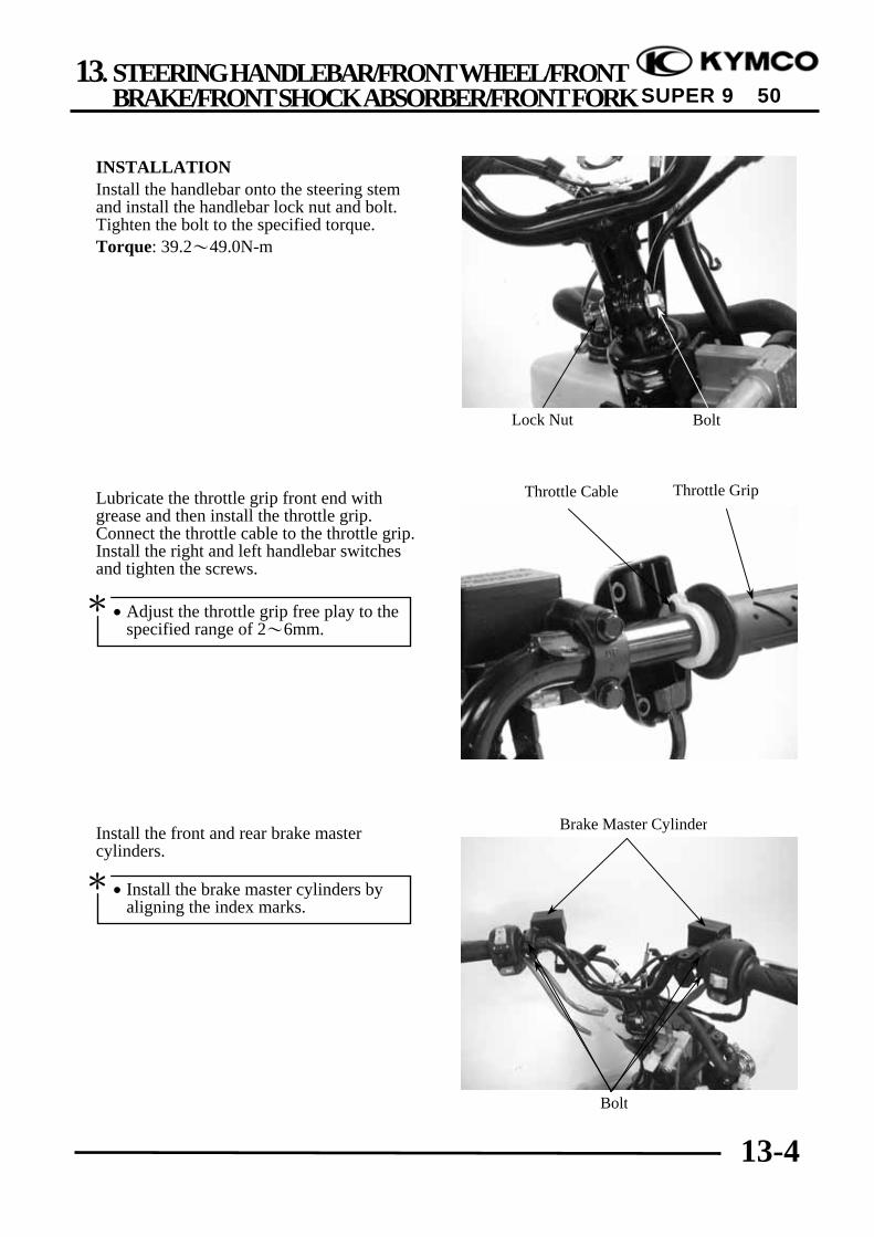
13. STEERING HANDLEBAR/FRONT WHEEL/FRONTBRAKE/FRONT SHOCK ABSORBER/FRONT FORK
13-4
SUPER 9 50
INSTALLATIONInstall the handlebar onto the steering stemand install the handlebar lock nut and bolt.Tighten the bolt to the specified torque.Torque: 39.2~49.0N-m
Lubricate the throttle grip front end withgrease and then install the throttle grip.Connect the throttle cable to the throttle grip.Install the right and left handlebar switchesand tighten the screws.
Install the front and rear brake mastercylinders.
Throttle GripThrottle Cable
Bolt
BoltLock Nut
Brake Master Cylinder
• Adjust the throttle grip free play to thespecified range of 2~6mm.
*
• Install the brake master cylinders byaligning the index marks.
*

13. STEERING HANDLEBAR/FRONT WHEEL/FRONTBRAKE/FRONT SHOCK ABSORBER/FRONT FORK
13-5
SUPER 9 50
FRONT WHEELREMOVALJack the motorcycle front wheel off theground.Remove the front axle nut to pull out the axle.Remove the front wheel and the speedometergear unit.
INSPECTIONAXLE RUNOUTSet the axle in V blocks and measure therunout using a dial gauge.The actual runout is ½ of the total indicatorreading.Service Limit: 0.2mm replace if over
WHEEL RIMCheck the wheel rim runout.Service Limits: Radial:2.0mm replace if over Axial:2.0mm replace if over
Axle Nut Speedometer Gear Unit
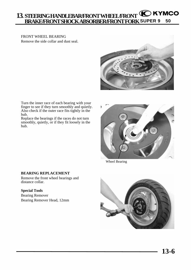
13. STEERING HANDLEBAR/FRONT WHEEL/FRONTBRAKE/FRONT SHOCK ABSORBER/FRONT FORK
13-6
SUPER 9 50
FRONT WHEEL BEARINGRemove the side collar and dust seal.
Turn the inner race of each bearing with yourfinger to see if they turn smoothly and quietly.Also check if the outer race fits tightly in thehub.Replace the bearings if the races do not turnsmoothly, quietly, or if they fit loosely in thehub.
BEARING REPLACEMENTRemove the front wheel bearings anddistance collar.
Special ToolsBearing RemoverBearing Remover Head, 12mm
Wheel Bearing

13. STEERING HANDLEBAR/FRONT WHEEL/FRONTBRAKE/FRONT SHOCK ABSORBER/FRONT FORK
13-7
SUPER 9 50
Pack all bearing cavities with grease.Drive in the left bearing.Install the distance collar.Drive in the right bearing.
Special ToolsOuter driverDriver handle
INSTALLATIONApply grease to the speedometer gear unit.Install the speedometer gear unit by aligningits retaining pawl with the hub cutout.
Install the front wheel by aligning thespeedometer gear unit groove with the frontshock absorber tab.Insert the axle and tighten the axle nut.
Torque: 44.1~49.0N-m
•Do not allow the bearings to tilt whiledriving them in.
•Drive in the bearing squarely with thesealed end facing out.
*
Tab
Groove Speedometer Gear Unit
PawlHub Cutout
Speedometer Gear Unit
Driver Handle
Outer Driver
When installing the front wheel, positionthe brake disk between the two brakepads.
*
• If not aligned, the retaining pawl willbe deformed when the axle nut istightened.
•After installing the axle, turn the wheelto make sure that the speedometer driveshaft rotates freely.
*

13. STEERING HANDLEBAR/FRONT WHEEL/FRONTBRAKE/FRONT SHOCK ABSORBER/FRONT FORK
13-8
SUPER 9 50
FRONT BRAKEBRAKE MASTER CYLINDERREMOVALRemove the handlebar covers. ( 2-7)First drain the brake fluid from the hydraulicbrake system.Disconnect the front stop switch wireconnector.Remove the brake fluid tube bolt.Remove the two bolts attaching the brakemaster cylinderRemove the brake master cylinder.
DISASSEMBLYRemove the brake lever bolt and the brakelever.Remove the piston rubber cover and snapring from the brake master cylinder.
Remove the washer, main piston and springfrom the brake master cylinder.Clean the inside of the master cylinder andbrake reservoir with brake fluid.
Rubber Cover
• When servicing the brake system, useshop towels to cover rubber and plasticparts and coated surfaces to avoidbeing contaminated by brake fluid.
• When removing the brake fluid tubebolt, be sure to plug the tube end toavoid brake fluid leakage.
*
Bolts
Stop Switch Wire Connector
Holder
Main PistonSpringMaster Cylinder
Snap Ring
Snap Ring
Snap Ring Pliers (Close)
Rubber Cover

13. STEERING HANDLEBAR/FRONT WHEEL/FRONTBRAKE/FRONT SHOCK ABSORBER/FRONT FORK
13-9
SUPER 9 50
INSPECTIONMeasure the brake master cylinder I.D.Inspect the master cylinder for scratches orcracks.Service Limit: 12.75mm
Measure the brake master cylinder pistonO.D.Service Limit: 12.645mmBefore assembly, inspect the lst and 2ndrubber cups for wear.
ASSEMBLYBefore assembly, apply brake fluid to allremoved parts.Install the spring together with the 1st rubbercup.
Install the main piston, spring and snap ring.Install the rubber cover.Install the brake lever.
• During assembly, the main piston andspring must be installed as a unitwithout exchange.
• When assembling the piston, soak thecups in brake fluid for a while.
• Install the cups with the cup lips facingthe correct direction.
*
Rubber Cover
Main PistonSpringMaster Cylinder
Snap Ring

13. STEERING HANDLEBAR/FRONT WHEEL/FRONTBRAKE/FRONT SHOCK ABSORBER/FRONT FORK
13-10
SUPER 9 50
Place the brake master cylinder on thehandlebar and install the holder with the “up”mark facing up. Also align the punch markwith the holder joint seam.First tighten the upper bolt and then tightenthe lower bolt.Torque: 9.8~13.72N-m
Install the brake fluid tube with the attachingbolt and two sealing washers.Connect the front stop switch wire connector.Install the handlebar covers. ( 2-7)
BRAKE FLUID REFILLINGKeep the handlebar upright and remove thebrake reservoir cover and diaphragm.Add DOT-3 brake fluid to the brakereservoir.
Stop Switch Wire Connector
Fluid Tube Bolt “Up” Mark
• When bleeding, be careful not to allowair in the brake reservoir flowing intothe brake system.
• When using a brake bleeder, follow themanufacturer‘s instructions.
• Never use dirty or unspecified brakefluid or mix different brake fluids be-cause it will damage the brake system.
*

13. STEERING HANDLEBAR/FRONT WHEEL/FRONTBRAKE/FRONT SHOCK ABSORBER/FRONT FORK
13-11
SUPER 9 50
BRAKE FLUID BLEEDINGKeep the handlebar upright and remove thebrake reservoir cover and diaphragm. Addthe specified brake fluid to the upper limit.
In order to avoid spilling brake fluid, connecta transparent hose to the bleed valve.
Fully apply the brake lever and then loosenthe brake caliper bleed valve to drain thebrake fluid until there is no air bubbles in thebrake fluid. Then, tighten the bleed valve.Repeat these steps until the brake system isfree of air.
BRAKE CALIPERREMOVALFirst drain the brake fluid from the hydraulicbrake system.Remove the brake fluid tube bolt.Remove the two bolts attaching the brakecaliper.Remove the brake caliper.
DISASSEMBLYRemove the two brake pads dowel pins fromthe brake caliper.Remove the brake pads.
Dowel Pin
Fluid Tube Bolt
Bleed Valve
Brake Pad
Bolts
Brake fluid spilled on brake pads orbrake disk will reduce the braking effect.Clean the brake pads and brake disk witha high quality brake degreaser.
Warning Bleed Valve
• Do not allow dust or water to enter thebrake system during refilling.
• When servicing the brake system, useshop towels to cover plastic parts andcoated surfaces to avoid damagecaused by splash of brake fluid.
*

13. STEERING HANDLEBAR/FRONT WHEEL/FRONTBRAKE/FRONT SHOCK ABSORBER/FRONT FORK
13-12
SUPER 9 50
Remove the piston from the brake caliper.If necessary, use compressed air to squeezeout the piston through the brake fluid inletopening and place a shop towel under thecaliper to avoid contamination caused by theremoved piston.Check the piston cylinder for scratches orwear and replace if necessary.
Push the piston oil seal outward to remove it.Clean the oil seal groove with brake fluid.
Check the piston for scratches or wear.Measure the piston O.D. with a micrometergauge.Service Limit: 25.30mm
Compressed Air
Piston Oil Seal
Be careful not to damage the pistonsurface.
*
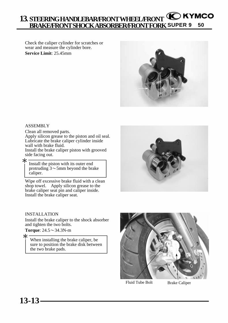
13. STEERING HANDLEBAR/FRONT WHEEL/FRONTBRAKE/FRONT SHOCK ABSORBER/FRONT FORK
13-13
SUPER 9 50
Check the caliper cylinder for scratches orwear and measure the cylinder bore.Service Limit: 25.45mm
ASSEMBLYClean all removed parts.Apply silicon grease to the piston and oil seal.Lubricate the brake caliper cylinder insidewall with brake fluid.Install the brake caliper piston with groovedside facing out.
Wipe off excessive brake fluid with a cleanshop towel. Apply silicon grease to thebrake caliper seat pin and caliper inside.Install the brake caliper seat.
INSTALLATIONInstall the brake caliper to the shock absorberand tighten the two bolts.Torque: 24.5~34.3N-m
Fluid Tube Bolt Brake Caliper
When installing the brake caliper, besure to position the brake disk betweenthe two brake pads.
*
Install the piston with its outer endprotruding 3~5mm beyond the brakecaliper.
*

13. STEERING HANDLEBAR/FRONT WHEEL/FRONTBRAKE/FRONT SHOCK ABSORBER/FRONT FORK
13-14
SUPER 9 50
Connect the brake fluid tube to the brakecaliper and tighten the fluid tube bolt.Torque: 24.5~34.3N-mFill the brake reservoir with the specifiedbrake fluid and bleed air from the brakesystem. ( 13-11)
FRONT SHOCK ABSORBERREMOVALRemove the front upper cover. ( 2-3)Remove the front lower cover. ( 2-3)Remove the front wheel. ( 13-5)Remove the front brake caliper. ( 13-11)Remove the front shock absorber uppermount bolts.Loosen the lower mount bolts to remove thefront shock absorbers.
DISASSEMBLYRemove the dust boot.Remove the dust seal.Remove the circlip.
Circlip
Shock Absorber Mount Bolts
Dust Boot
Front Fork
Dust Seal
When installing the brake fluid tube, besure to install the two sealing washers.
*
Fluid Tube Bolt Washers
Brake Fluid Tube

13. STEERING HANDLEBAR/FRONT WHEEL/FRONTBRAKE/FRONT SHOCK ABSORBER/FRONT FORK
13-15
SUPER 9 50
Set the front shock absorber in a vise.Remove the damper rod hex bolt and copperwasher.Pull out the front shock absorber tube.
Set the front shock absorber tube in a vise.Remove the lock nut on the front shockabsorber tube.Take out the shock absorber spring anddamper rod.
INSPECTIONInspect the following items and replace ifnecessary.•Front shock absorber tube bending, damageor wear•Weak front shock absorber spring•Damper and damper rod bending•Oil seal damage or wear
Shock Absorber Tube
Shock Absorber Tube
After the hex bolt is removed, place acontainer under the front shock absorberto drain the engine oil from it.
*
Hex Bolt
Lock Nut
When holding the shock absorber tube,place a shop towel to protect it and doapply too much force .
*

13. STEERING HANDLEBAR/FRONT WHEEL/FRONTBRAKE/FRONT SHOCK ABSORBER/FRONT FORK
13-16
SUPER 9 50
Measure the front shock absorber spring freelength.Service Limit: 233mm replace if below
ASSEMBLYInstall the damper spring onto the damper rodand then install them into the front shockabsorber tube.Install the shock absorber spring onto thefront shock absorber tube.Set the front shock absorber tube in a viseand then tighten the lock nut.
Set the front shock absorber in a vise.Insert the shock absorber tube into the shockabsorber and then install the copper washerand tighten the damper rod hex bolt.
Add engine oil into the front shock absorber.Torque: 14.7~29.4N-mSpecified Oil: SS#8Oil Capacity: 52cc
Hex Bolt
Apply locking agent to the washer andhex bolt and install them together.
*
When holding the shock absorber tube,place a shop towel to protect it and doapply too much force .
*
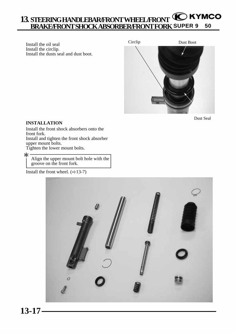
13. STEERING HANDLEBAR/FRONT WHEEL/FRONTBRAKE/FRONT SHOCK ABSORBER/FRONT FORK
13-17
SUPER 9 50
Install the oil sealInstall the circlip.Install the dusts seal and dust boot.
INSTALLATIONInstall the front shock absorbers onto thefront fork.Install and tighten the front shock absorberupper mount bolts.Tighten the lower mount bolts.
Install the front wheel. ( 13-7)
Circlip Dust Boot
Dust Seal
Align the upper mount bolt hole with thegroove on the front fork.
*
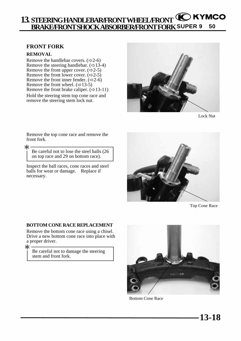
13. STEERING HANDLEBAR/FRONT WHEEL/FRONTBRAKE/FRONT SHOCK ABSORBER/FRONT FORK
13-18
SUPER 9 50
FRONT FORKREMOVALRemove the handlebar covers. ( 2-6)Remove the steering handlebar. ( 13-4)Remove the front upper cover. ( 2-5)Remove the front lower cover. ( 2-5)Remove the front inner fender. ( 2-6)Remove the front wheel. ( 13-5)Remove the front brake caliper. ( 13-11)Hold the steering stem top cone race andremove the steering stem lock nut.
Remove the top cone race and remove thefront fork.
Inspect the ball races, cone races and steelballs for wear or damage. Replace ifnecessary.
BOTTOM CONE RACE REPLACEMENTRemove the bottom cone race using a chisel.Drive a new bottom cone race into place witha proper driver.
Top Cone Race
Lock Nut
Bottom Cone Race
Be careful not to damage the steeringstem and front fork.
*
Be careful not to lose the steel balls (26on top race and 29 on bottom race).
*
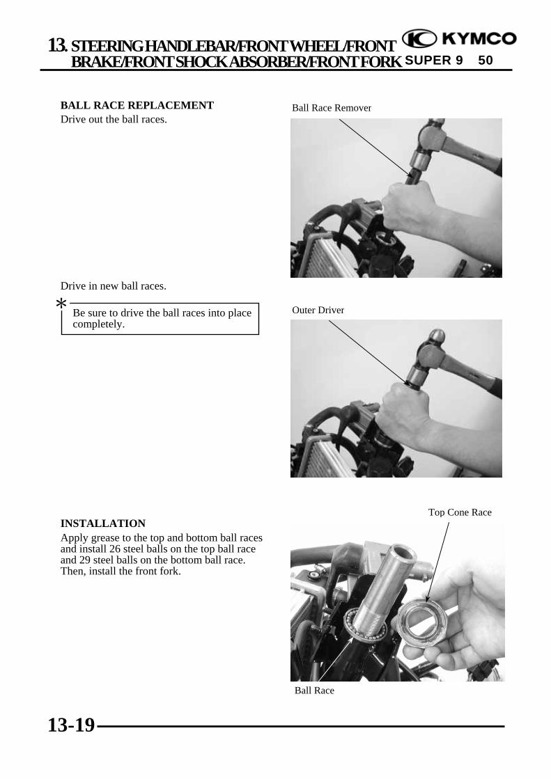
13. STEERING HANDLEBAR/FRONT WHEEL/FRONTBRAKE/FRONT SHOCK ABSORBER/FRONT FORK
13-19
SUPER 9 50
BALL RACE REPLACEMENTDrive out the ball races.
Drive in new ball races.
INSTALLATIONApply grease to the top and bottom ball racesand install 26 steel balls on the top ball raceand 29 steel balls on the bottom ball race.Then, install the front fork.
Ball Race Remover
Top Cone Race
Ball Race
Outer DriverBe sure to drive the ball races into placecompletely.
*

13. STEERING HANDLEBAR/FRONT WHEEL/FRONTBRAKE/FRONT SHOCK ABSORBER/FRONT FORK
13-20
SUPER 9 50
Apply grease to the top cone race and installit.Tighten the top cone race and then turn thesteering stem right and left several times tomake steel balls contact each other closely.
Install the steering stem lock nut and tightenit while holding the top cone race.Torque: 78.4~117.6N-mInstall the front wheel. ( 13-7)Install the front brake caliper. ( 13-12)Install the front inner fender. ( 2-6)Install the throttle grip and the right and lefthandlebar switches.( 13-5)Install the right and left brake mastercylinders. ( 13-5)
Lock Nut Wrench Lock Nut Socket
Check that the steering stem rotatesfreely without vertical play.
*
14. REAR BRAKE/REAR FORK/REARWHEEL/REAR SHOCK ABSORBER
14-0
SUPER 9 50
14 __________________________________________________________________________________
__________________________________________________________________________________
__________________________________________________________________________________
__________________________________________________________________________________
__________________________________________________________________________________
REAR BRAKE/REAR FORK/REAR WHEEL/REAR SHOCK ABSORBER
__________________________________________________________________________________
SERVICE INFORMATION------------------------------------------------ 14-1TROUBLESHOOTING----------------------------------------------------- 14-1REAR BRAKE --------------------------------------------------------------- 14-2REAR FORK ----------------------------------------------------------------- 14-3REAR WHEEL--------------------------------------------------------------- 14-3REAR BRAKE DRUM ----------------------------------------------------- 14-5REAR SHOCK ABSORBER ---------------------------------------------- 14-7
14
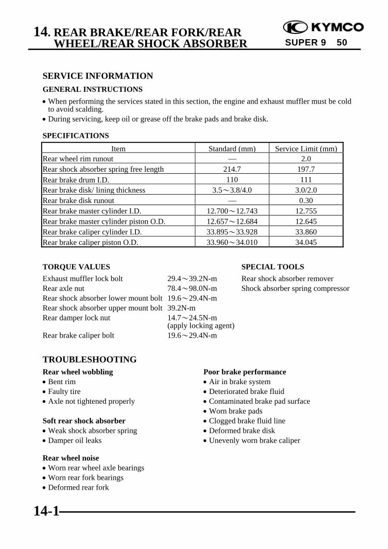
14. REAR BRAKE/REAR FORK/REARWHEEL/REAR SHOCK ABSORBER
14-1
SUPER 9 50
SERVICE INFORMATIONGENERAL INSTRUCTIONS• When performing the services stated in this section, the engine and exhaust muffler must be cold
to avoid scalding.• During servicing, keep oil or grease off the brake pads and brake disk.
SPECIFICATIONS
Item Standard (mm) Service Limit (mm)Rear wheel rim runout ⎯ 2.0Rear shock absorber spring free length 214.7 197.7Rear brake drum I.D. 110 111Rear brake disk/ lining thickness 3.5~3.8/4.0 3.0/2.0Rear brake disk runout ⎯ 0.30Rear brake master cylinder I.D. 12.700~12.743 12.755Rear brake master cylinder piston O.D. 12.657~12.684 12.645Rear brake caliper cylinder I.D. 33.895~33.928 33.860Rear brake caliper piston O.D. 33.960~34.010 34.045
TORQUE VALUES SPECIAL TOOLSExhaust muffler lock bolt 29.4~39.2N-m Rear shock absorber removerRear axle nut 78.4~98.0N-m Shock absorber spring compressorRear shock absorber lower mount bolt 19.6~29.4N-mRear shock absorber upper mount bolt 39.2N-mRear damper lock nut 14.7~24.5N-m
(apply locking agent)Rear brake caliper bolt 19.6~29.4N-m
TROUBLESHOOTINGRear wheel wobbling Poor brake performance• Bent rim • Air in brake system• Faulty tire • Deteriorated brake fluid• Axle not tightened properly • Contaminated brake pad surface
• Worn brake padsSoft rear shock absorber • Clogged brake fluid line• Weak shock absorber spring • Deformed brake disk• Damper oil leaks • Unevenly worn brake caliper
Rear wheel noise• Worn rear wheel axle bearings• Worn rear fork bearings• Deformed rear fork

14. REAR BRAKE/REAR FORK/REARWHEEL/REAR SHOCK ABSORBER
14-2
SUPER 9 50
REAR BRAKE (SH10DA)REAR BRAKE CALIPER REMOVALFirst remove the exhaust muffler. ( 2-6)Remove the rear brake fluid tube bolt anddisconnect the brake fluid tube.Remove the two bolts attaching the rear brakecaliper.Remove the rear brake caliper.
INSPECTIONInspect the brake pads and brake disk.Visually check the brake pad thickness and itshould not exceed the wear indicator mark.Measure the brake disk thickness.Service Limit: 3.0mm replace if belowDISASSEMBLYDisassemble the rear brake caliper. ( 14-11)Inspect and assemble the rear brake caliper .( 14-12)Note: The rear brake caliper and front brake
caliper have the same specification.
INSTALLATIONInstall the brake caliper to the rear fork andtighten the two bolts.Torque: 24.5~34.3N-mConnect the brake fluid tube to the brakecaliper and tighten the fluid tube bolt.Fill the brake reservoir with the specifiedbrake fluid and bleed air from the brakesystem. ( 13-11)
When removing the brake fluid tube, useshop towels to cover plastic parts andcoated surfaces to avoid damage.
*
Brake Disk
Fluid Tube Bolt
Brake Pads
Bolts
Copper Washers
Brake Caliper
Wear Indicator Mark
Fluid Tube Bolt Bolts
When installing the brake fluid tube, besure to install the two copper sealingwashers.
*

14. REAR BRAKE/REAR FORK/REARWHEEL/REAR SHOCK ABSORBER
14-3
SUPER 9 50
REAR FORK (SF10DA)REMOVALRemove the exhaust muffler. ( 2-6)Remove the rear brake caliper. ( 14-2)Remove the rear axle nut and remove thecollar.Remove the rear fork.The installation sequence is the reverse ofremoval.Torque: Rear fork bolt: 19.6~29.4N-m Rear axle nut: 78.4~98.0N-m
REAR WHEELREMOVALRemove the exhaust muffler. ( 2-6)Remove the rear brake caliper. ( 14-2)Remove the rear fork.Remove the rear axle collar.Remove the rear wheel.
REMOVALRemove the exhaust muffler. ( 2-6)Remove the rear axle nut to remove the rearwheel.
Collar
Rear Axle Collar
Rear Fork Bolts
Rear Brake Disk
Rear Axle Nut
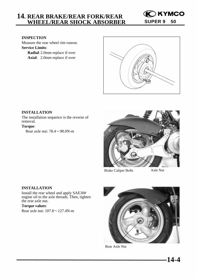
14. REAR BRAKE/REAR FORK/REARWHEEL/REAR SHOCK ABSORBER
14-4
SUPER 9 50
INSPECTIONMeasure the rear wheel rim runout.Service Limits: Radial:2.0mm replace if over Axial: 2.0mm replace if over
INSTALLATIONThe installation sequence is the reverse ofremoval.Torque: Rear axle nut: 78.4~98.0N-m
INSTALLATIONInstall the rear wheel and apply SAE30#engine oil to the axle threads. Then, tightenthe rear axle nut.Torque values:Rear axle nut: 107.8~127.4N-m
Axle NutBrake Caliper Bolts
Rear Axle Nut
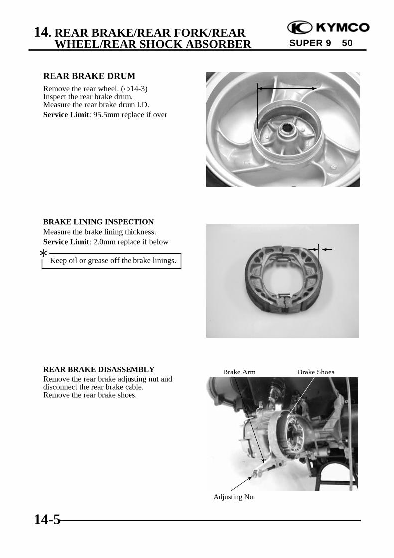
14. REAR BRAKE/REAR FORK/REARWHEEL/REAR SHOCK ABSORBER
14-5
SUPER 9 50
REAR BRAKE DRUMRemove the rear wheel. ( 14-3)Inspect the rear brake drum.Measure the rear brake drum I.D.Service Limit: 95.5mm replace if over
BRAKE LINING INSPECTIONMeasure the brake lining thickness.Service Limit: 2.0mm replace if below
REAR BRAKE DISASSEMBLYRemove the rear brake adjusting nut anddisconnect the rear brake cable.Remove the rear brake shoes.
Keep oil or grease off the brake linings.*
Adjusting Nut
Brake Arm Brake Shoes

14. REAR BRAKE/REAR FORK/REARWHEEL/REAR SHOCK ABSORBER
14-6
SUPER 9 50
Remove the brake arm bolt to remove thebrake arm, wear indicator plate and felt seal.Remove the brake cam.
REAR BRAKE ASSEMBLYApply grease to the anchor pin and brakeshoe moving parts.Apply grease to the brake cam and install it.
Apply engine oil to the felt seal and install itto the brake cam.Install the wear indicator plate.
Install the brake arm onto the brake cam.
Install and tighten the brake arm bolt.Install the brake arm return spring.Install the brake shoes.
Brake Arm Bolt Wear Indicator Plate
Brake Arm Brake Cam
Grease
Brake Arm
Wear Indicator Plate
Align the wide tooth of the wearindicator plate with the wide groove onthe brake cam.
*
Align the punch mark on the brake armwith the scribed line on the brake cam.
*

14. REAR BRAKE/REAR FORK/REARWHEEL/REAR SHOCK ABSORBER
14-7
SUPER 9 50
Install the brake arm pin.Connect the brake cable and install theadjusting nut.Install the rear wheel.Adjust the rear brake lever free play. ( 3-12)
REAR SHOCK ABSORBERREMOVALRemove the rear carrier and frame body cover.( 2-2)Remove the met-in box. ( 2-2)Remove the two air cleaner bolts.
Remove the rear shock absorber upper mountbolt.Remove the left rear shock absorber upperand lower mount bolts.Remove the left rear shock absorbers.
Bolts
Lower Mount Bolts
Air Cleaner
Brake Arm
Adjusting Nut Brake Arm Pin
Brake Cable

14. REAR BRAKE/REAR FORK/REARWHEEL/REAR SHOCK ABSORBER
14-8
SUPER 9 50
DISASSEMBLYDisassemble the left rear shock absorbersusing the rear shock absorber remover.
INSPECTIONInspect the damper rod for bending ordamage.Inspect the damper for oil leaks.Inspect the damper rubber for deterioration ordamage.
Measure the front shock absorber spring freelength.Service Limit: Left : 226mm
Rear Shock Absorber Remover
Damper Damper Rod Rubber
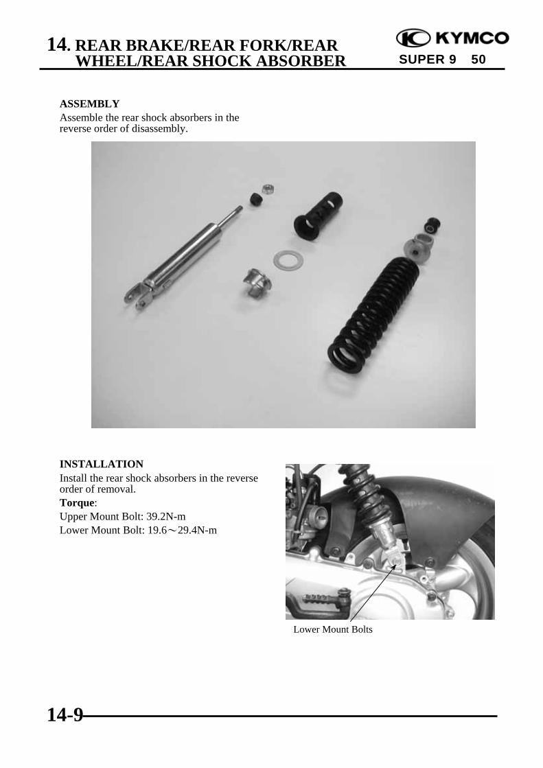
14. REAR BRAKE/REAR FORK/REARWHEEL/REAR SHOCK ABSORBER
14-9
SUPER 9 50
ASSEMBLYAssemble the rear shock absorbers in thereverse order of disassembly.
INSTALLATIONInstall the rear shock absorbers in the reverseorder of removal.Torque:Upper Mount Bolt: 39.2N-mLower Mount Bolt: 19.6~29.4N-m
Lower Mount Bolts
15. ELECTRICAL EQUIPMENT
15-0
SUPER 9 50
15 __________________________________________________________________________________
__________________________________________________________________________________
__________________________________________________________________________________
__________________________________________________________________________________
__________________________________________________________________________________
ELECTRICAL EQUIPMENT__________________________________________________________________________________
SERVICE INFORMATION ................................................................ 15- 1TROUBLESHOOTING ....................................................................... 15- 1CHARGING SYSTEM ........................................................................ 15- 3BATTERY............................................................................................ 15- 4IGNITION SYSTEM ........................................................................... 15- 7STARTING SYSTEM.......................................................................... 15-11
15
15. ELECTRICAL EQUIPMENT
15-1
SUPER 9 50
SERVICE INFORMATION
GENERAL INSTRUCTIONS• It is not necessary to check the battery electrolyte or fill with distilled water.• Remove the battery from the motorcycle for charging. Do not remove the electrolyte cap..• Do not quick charge the battery. Quick charging should only be done in an emergency..• Charge the battery according to the charging current and time specified on the battery.• When charging, check the voltage (open voltage) with an electric tester.• When replacing the battery, do not use a traditional battery.
SPECIFICATIONS SH10DA SF10DACapacity 12V4AH 12V4AHVoltage 13.0~13.2V 13.0~13.2V
Charging Standard 0.4A/5H 0.4A/5HBattery
current Quick 5A/0.5H 4A/0.5HSpark plug (NGK) BR8HSA BR8HSA
Spark plug gap 0.6~0.7mm 0.6~0.7mmPrimary coil 0.153~0.187Ω 0.153~0.187ΩSecondary coil(with plug cap) 6.99~10.21KΩ 6.99~10.21KΩIgnition coil resistanceSecondary coil(without plug cap) 3.24~3.96KΩ 3.24~3.96KΩ
Pulser coil resistance (20) 80~160Ω 80~160ΩIgnition timing 13.5°±2°BTDC/1800rpm 13.5°±2°BTDC/2000rpm
TROUBLESHOOTING
CHARGING SYSTEM
No power Intermittent power• Dead battery • Loose battery cable connection• Disconnected battery cable • Loose charging system connection• Fuse burned out • Loose connection or short circuit in ignition system• Faulty ignition switch • Loose connection or short circuit in lighting system
Low power Charging system failure• Weak battery • Loose, broken or shorted wire or connector• Loose battery connection • Faulty regulator/rectifier• Charging system failure • Faulty A.C. generator• Faulty regulator/rectifier

15. ELECTRICAL EQUIPMENT
15-2
SUPER 9 50
IGNITION SYSTEM
No spark at plug Engine starts but turns poorly• Faulty spark plug • Ignition primary circuit• Poorly connected, broken or shorted wire —Faulty ignition coil
—Between A.C. generator and CDI unit —Poorly connected wire or connector—Between CDI unit and ignition coil • Ignition secondary circuit—Between CDI unit and ignition switch —Faulty ignition coil—Between ignition coil and spark plug —Faulty spark plug
• Faulty ignition switch —Poorly insulated plug cap• Faulty ignition coil • Improper ignition timing• Faulty CDI unit —Battery voltage too low (6V max.)• Faulty A.C. generator —Faulty CDI unit
STARTING SYSTEM
Starter motor won‘t turn Lack of power• Fuse burned out • Weak battery• Weak battery • Loose wire or connection• Faulty ignition switch • Foreign matter stuck in starter motor• Faulty starter switch or pinion• Faulty front or rear stop switch Starter motor rotates but engine does• Faulty starter relay not start• Poorly connected, broken or shorted wire • Faulty starter pinion• Faulty starter motor • Starter motor rotates reversely
• Faulty starter clutch• Weak battery
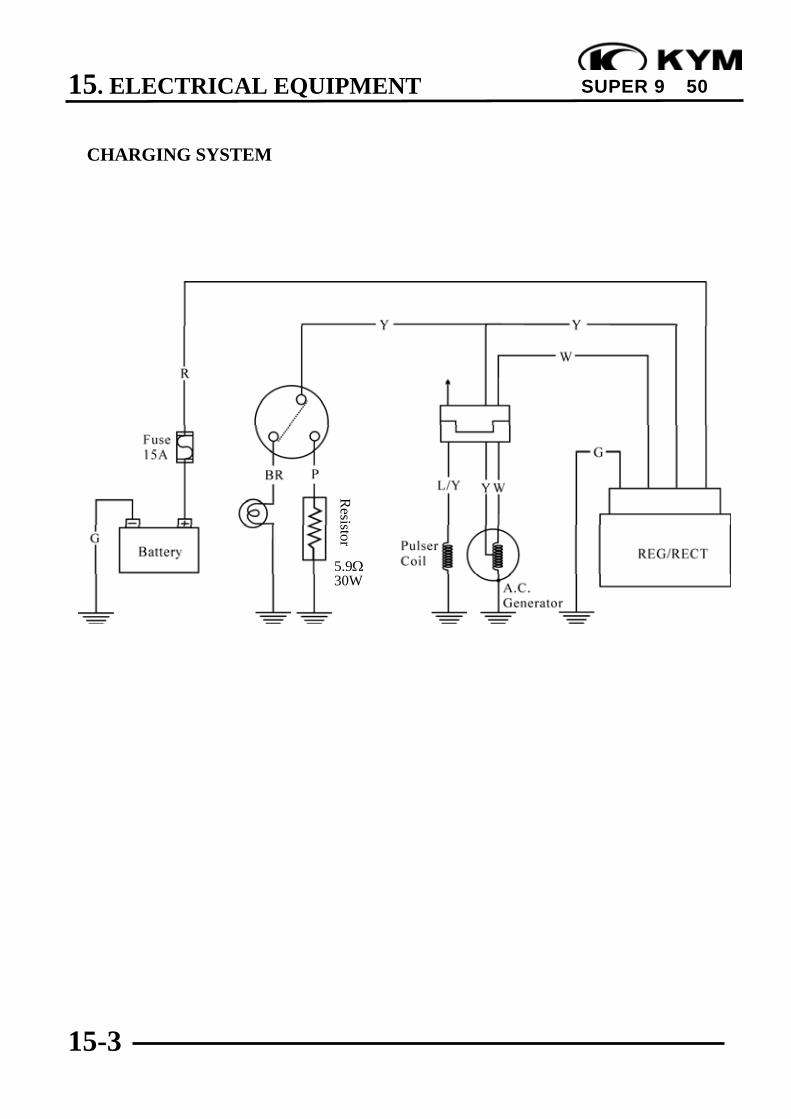
15. ELECTRICAL EQUIPMENT
15-3
SUPER 9 50
CHARGING SYSTEM
5.9Ω30W
Resistor

15. ELECTRICAL EQUIPMENT
15-4
SUPER 9 50
BATTERYBATTERY REMOVALOpen the front tool box and remove the bolt.Remove the front tool box. ( 2-4)Disconnect the battery cables.
Remove the bolt and battery bracket.Remove the battery.The installation sequence is the reverse ofremoval.BATTERY CHARGING (OPEN CIRCUITVOLTAGE) INSPECTIONRemove the battery cover and disconnect thebattery cables.Measure the voltage between the batteryterminals.Fully charged : 13.0V~13.2VUndercharged : 12.3V max.
CHARGING METHODConnect the charger positive (+) cable to thebattery positive (+) cable.Connect the charger negative (-) cable to thebattery negative (-) cable.
Charging current: Standard : 0.4AQuick : 4A
Charging time : Standard : 5 hoursQuick : 0.5 hours
After charging: Open circuit voltage: 12.8V min.
Front Tool Box
First disconnect the battery negative (-)cable and then the positive (+) cable.
*
Battery charging inspection must beperformed with an electric tester.
*
• Quick charging should only be done inan emergency.
• During quick charging, the batterytemperature should not exceed 45.
• Measure the voltage 30 minutes afterthe battery is charged.
*
•Keep flames and sparks away from acharging battery.
•Turn power ON/OFF at the charger,not at the battery terminals to preventsparks near the battery.
•Charge the battery according to thecurrent specified on the battery surface.
*
Power Lamp (Green)
Red
Black
Charging Lamp (Red)
Battery

15. ELECTRICAL EQUIPMENT
15-5
SUPER 9 50
PERFORMANCE TESTWarm up the engine.Remove the floor mat and battery cover.
Stop the engine and open the fuse box.Disconnect the wire lead from the fuseterminal. Connect an ammeter between thewire lead and fuse terminal as shown.Connect the battery positive (+) terminal tothe voltmeter positive (+) probe and batterynegative (-) terminal to the voltmeter negative(-) probe.Start the engine, gradually increase enginespeed to test the output:
PositionRPM Day Night
2500 1.3A min. 1.0A min.6000 2.0A min. 2.0A min.
Charging Limit Voltage: 14.5±0.5V/8000rpmIf the limit voltage is not within the specifiedrange, check the regulator/ rectifier.
A.C. GENERATOR (CHARGINGCOIL) INSPECTION
Remove the met-in box, rear carrier andframe body cover. ( 2-2)Disconnect the A.C. generator connector.Measure the resistances between the chargingcoil terminals (white–green) and lighting coilterminals (yellow–green).Resistances:Charging coil white–green 0.2~1.2ΩLighting coil yellow–green 0.3~1.0Ω
Refer to 8-3 for A.C. generator removal.
A.C. Generator Connector
Use a fully charged battery to check thecharging system output.
*
Inspect with the engine installed.*

15. ELECTRICAL EQUIPMENT
15-6
SUPER 9 50
RESISTOR INSPECTIONRemove the front upper/lower cover. ( 2-3)Measure the resistance between the resistor Bpink wire and ground.Measure the resistance between the resistor Agreen/black wire and ground.Resistances: Resistor A: 9.9~10.5Ω Resistor B: 5.6~6.2Ω
REGULATOR/RECTIFIERINSPECTIONRemove the front upper/lower cover. ( 2-3)Disconnect the regulator/rectifier wirecoupler and remove the bolt to remove theregulator/rectifier.
Measure the resistances between theterminals.Replace the regulator/rectifier if the readingsare not within the specifications in the tablebelow.
Model Brand RangeSP-10D Sanwa KΩTH-5H Kowa 100Ω
Probe⊕Probe(-) A (R) B (W) C (Y) D (G)
A (R) ∞ ∞ ∞
B (W) 3-10KΩ ∞ ∞
C (Y) ∞ ∞ 33-35KΩ
D (G) ∞ ∞ 33-35KΩ
• Due to the semiconductor in circuit, itis necessary to use a specified testerfor accurate testing. Use of animproper tester in an improper rangemay give false readings.
• Use a Sanwa Electric Tester (07208-0020000) or Kowa Electric Tester(TH-5H). The proper range fortesting is listed below.
*
Coupler
Faulty resistor is the cause of faultyoperation of the auto bystarter.
*
A (Red) C (Yellow)
D (Green)B (White)
Resister A Resister B
Regulator/Rectifier
Bolt

15. ELECTRICAL EQUIPMENT
15-7
SUPER 9 50
IGNITION SYSTEM
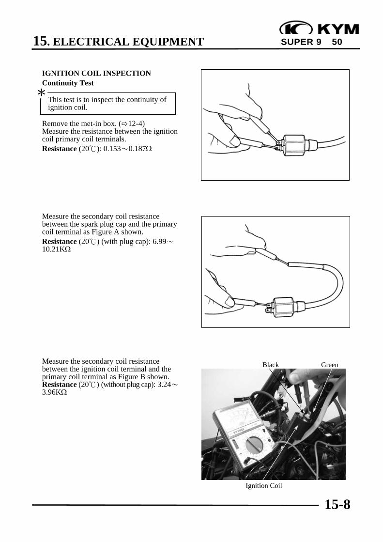
15. ELECTRICAL EQUIPMENT
15-8
SUPER 9 50
IGNITION COIL INSPECTIONContinuity Test
Remove the met-in box. ( 12-4)Measure the resistance between the ignitioncoil primary coil terminals.Resistance (20): 0.153~0.187Ω
Measure the secondary coil resistancebetween the spark plug cap and the primarycoil terminal as Figure A shown.Resistance (20) (with plug cap): 6.99~10.21KΩ
Measure the secondary coil resistancebetween the ignition coil terminal and theprimary coil terminal as Figure B shown.Resistance (20) (without plug cap): 3.24~3.96KΩ
This test is to inspect the continuity ofignition coil.
*
Ignition Coil
GreenBlack

15. ELECTRICAL EQUIPMENT
15-9
SUPER 9 50
Performance TestRemove the ignition coil.
Inspect the ignition coil with an ignition coiltester.
1. Turn the changeover switch to 12V andconnect the ignition coil to the tester.
2. Turn the power switch ON and check thespark from the watch window.
‧Good : Normal and continuous spark‧Faulty : Weak or intermittent spark
A.C. GENERATORExciter Coil/Pulser Coil Inspection
Remove the met-in box. ( 12-4)Disconnect the A.C. generator wireconnector.Measure the pulser coil resistance betweenthe blue/yellow wire and ground.Resistance (20): 80~160Ω
Ignition Coil
AC 110V6V/12VChangeoverSwitch
Ignition Coil Tester07508-0070100
Watch Window
Black
Black(-)
Red(+)
Black(-)
Red(+)
Blue/Yellow
This test is performed with the statorinstalled in the engine.
*
Follow the ignition coil tester manufac-turer‘s instructions.
*
The test is performed at both conditionsthat the ignition coil is cold and hot.
*
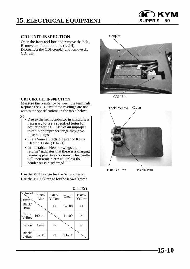
15. ELECTRICAL EQUIPMENT
15-10
SUPER 9 50
CDI UNIT INSPECTIONOpen the front tool box and remove the bolt.Remove the front tool box. ( 2-4)Disconnect the CDI coupler and remove theCDI unit.
CDI CIRCUIT INSPECTIONMeasure the resistance between the terminals.Replace the CDI unit if the readings are notwithin the specifications in the table below.
Use the x KΩ range for the Sanwa Tester.Use the x 100Ω range for the Kowa Tester.
Unit: KΩProbe⊕
(-)ProbeBlack/Blue
Blue/Yellow Green Black/
YellowBlack/Blue ∞ 1~100 ∞
Blue/Yellow 100~∞ 1~100 ∞
Green 1~∞ ∞ ∞
Black/Yellow 1~100 ∞ 0.1~50
• Due to the semiconductor in circuit, it isnecessary to use a specified tester foraccurate testing. Use of an impropertester in an improper range may givefalse readings.
• Use a Sanwa Electric Tester or KowaElectric Tester (TH-5H).
• In this table, “Needle swings thenreturns” indicates that there is a chargingcurrent applied to a condenser. The needlewill then remain at “∞” unless thecondenser is discharged.
*
CDI Unit
Blue/ Yellow
Green
Black/ Blue
Black/ Yellow
Coupler

15. ELECTRICAL EQUIPMENT
15-11
SUPER 9 50
STARTING SYSTEM
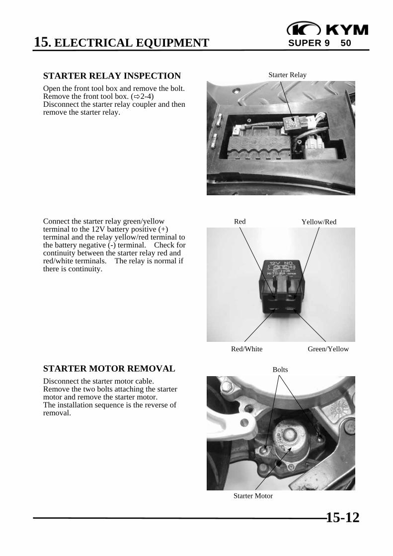
15. ELECTRICAL EQUIPMENT
15-12
SUPER 9 50
STARTER RELAY INSPECTIONOpen the front tool box and remove the bolt.Remove the front tool box. ( 2-4)Disconnect the starter relay coupler and thenremove the starter relay.
Connect the starter relay green/yellowterminal to the 12V battery positive (+)terminal and the relay yellow/red terminal tothe battery negative (-) terminal. Check forcontinuity between the starter relay red andred/white terminals. The relay is normal ifthere is continuity.
STARTER MOTOR REMOVALDisconnect the starter motor cable.Remove the two bolts attaching the startermotor and remove the starter motor.The installation sequence is the reverse ofremoval.
Starter Relay
Green/Yellow
Starter Motor
Red/White
Bolts
Yellow/RedRed

15. ELECTRICAL EQUIPMENT
15-13
SUPER 9 50
STARTER MOTOR INSPECTIONConnect a battery across the starter motor andcheck for its operation.
1. Do not turn the starter motor for along time.
2. This inspection should be done with afully charged battery.
*
Battery
Starter Motor Battery (+) Terminal
16. INSTRUMENT/SWITCHES/LIGHTS
16-0
SUPER 9 50
16 __________________________________________________________________________________
__________________________________________________________________________________
__________________________________________________________________________________
__________________________________________________________________________________
__________________________________________________________________________________
INSTRUMENT/SWITCHES/LIGHTS__________________________________________________________________________________
SERVICE INFORMATION ................................................................ 16-1TROUBLESHOOTING ....................................................................... 16-1FUEL UNIT.......................................................................................... 16-2OIL METER......................................................................................... 16-3SWITCHES .......................................................................................... 16-4STOP SWITCH INSPECTION/HORN ............................................... 16-6BULB REPLACEMENT ..................................................................... 16-7INSTRUMENT/HEADLIGHT ............................................................ 16-8
16

16. INSTRUMENT/SWITCHES/LIGHTS
16-1
SUPER 9 50
SERVICE INFORMATION
GENERAL INSTRUCTIONS• Wires should be connected to other wires of the same color. Couplers must be connected to
other couplers of the same color.• All plastic plugs have locking tabs that must be released before disconnecting, and must be
aligned when reconnecting.• After installation of each switch, a continuity check must be performed.
TROUBLESHOOTING
Lights do not come on when ignition Motor oil indicator light does not come onswitch is “ON” (when motor oil is insufficient)• Burned bulb • Fuse burned out• Faulty switch • Dead battery• Broken or shorted wire • Faulty ignition switch• Fuse burned out • Faulty instrument• Weak battery • Faulty oil meter• Poorly connected wire• Faulty winker Motor oil indicator light winks
• Loose wire connectionLight dims • Broken wire• Faulty ignition coil • Faulty oil meter• Wire or switch resistance too high• Faulty regulator/rectifier Fuel gauge pointer does not register
correctlyHeadlight does not change when dimmer • Disconnected wire or connectorswitch is turn to Hi or Lo • Broken wire• Faulty or burned bulb • Faulty float• Faulty dimmer switch • Faulty fuel unit
• Faulty instrument
Fuel gauge pointer fluctuates or swings• Loose wire connection• Faulty fuel unit• Faulty instrument

16. INSTRUMENT/SWITCHES/LIGHTS
16-2
SUPER 9 50
FUEL UNIT
REMOVALRemove the frame body cover. ( 2-3)Disconnect the fuel unit wire connectors.Turn the fuel unit retainer counterclockwiseto remove it.
Remove the fuel unit.
INSPECTIONRemove the fuel unit.Measure the resistance between the fuel unitwire terminals with the float at upper andlower positions.
Wire Terminals Upper LowerG~Y/W 33Ω 686ΩG~L/W 566Ω 53Ω
Y/W~L/W 600Ω 600Ω
FUEL GAUGE INSPECTIONConnect the fuel unit wire connectors andturn the ignition switch “ON”.
Check the fuel gauge needle for correctindication by moving the fuel unit float upand down.
Float Position Needle PositionUpper “F” (Full)Lower “E” (Empty)
No Smoking!*
Be careful not to bend or damage thefuel unit float arm.
*
Do not damage the fuel unit wire.*
Before performing the following test,operate the turn signals to determinethat the battery circuit is normal.
*
Fuel Unit Wire
Fuel Unit
G
Y/W L/W
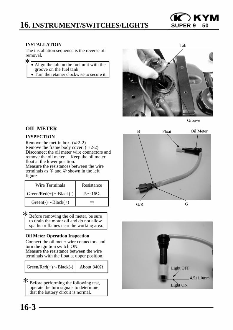
16. INSTRUMENT/SWITCHES/LIGHTS
16-3
SUPER 9 50
INSTALLATIONThe installation sequence is the reverse ofremoval.
OIL METERINSPECTIONRemove the met-in box. ( 2-2)Remove the frame body cover. ( 2-2)Disconnect the oil meter wire connectors andremove the oil meter. Keep the oil meterfloat at the lower position.Measure the resistances between the wireterminals as and shown in the leftfigure.
Wire Terminals Resistance
Green/Red(+)~Black(-) 5~16Ω
Green(-)~Black(+) ∞
Oil Meter Operation InspectionConnect the oil meter wire connectors andturn the ignition switch ON.Measure the resistance between the wireterminals with the float at upper position.
Green/Red(+)~Black(-) About 340Ω
• Align the tab on the fuel unit with thegroove on the fuel tank.
• Turn the retainer clockwise to secure it.
*
Light OFF
Light ONBefore performing the following test,operate the turn signals to determinethat the battery circuit is normal.
*
Groove
Oil MeterFloat
G/R
B
G
Before removing the oil meter, be sureto drain the motor oil and do not allowsparks or flames near the working area.
*
Tab
4.5±1.0mm
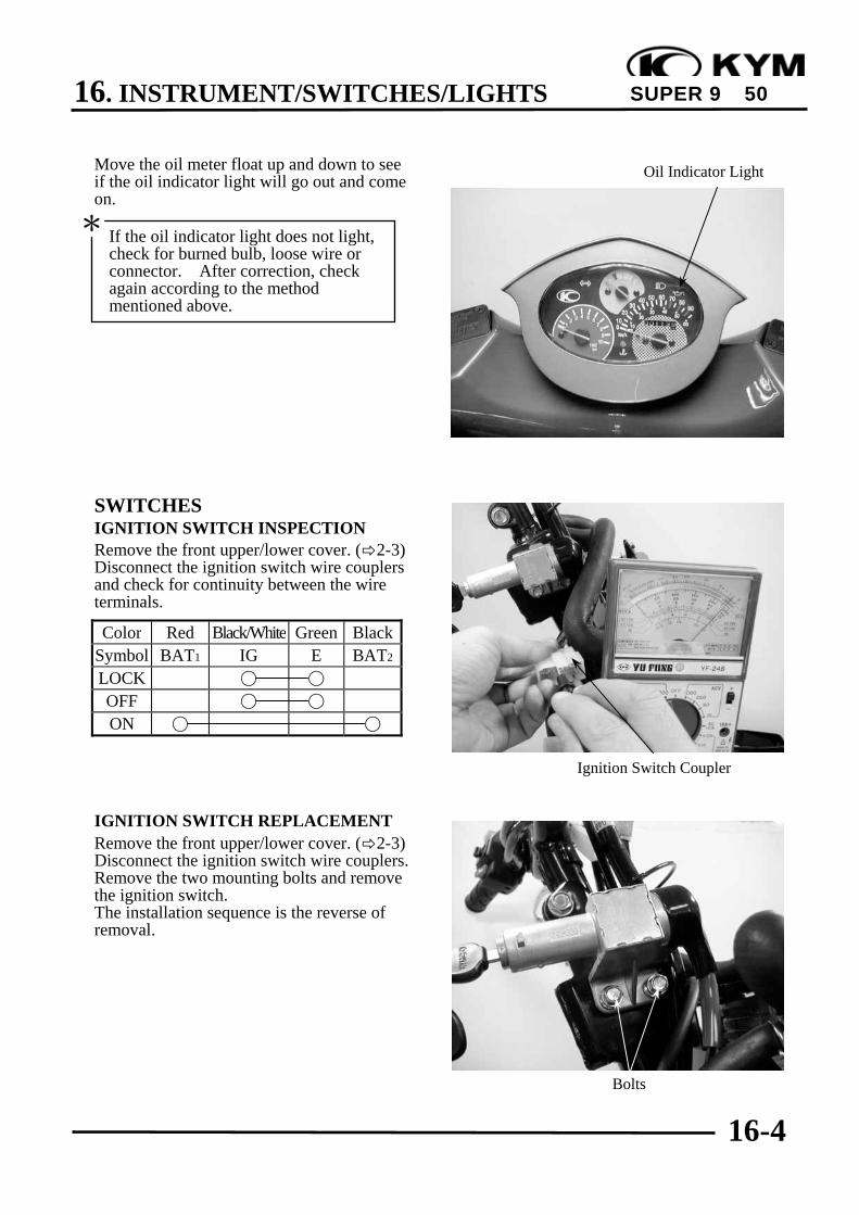
16. INSTRUMENT/SWITCHES/LIGHTS
16-4
SUPER 9 50
Move the oil meter float up and down to seeif the oil indicator light will go out and comeon.
SWITCHESIGNITION SWITCH INSPECTIONRemove the front upper/lower cover. ( 2-3)Disconnect the ignition switch wire couplersand check for continuity between the wireterminals.
Color Red Black/White Green BlackSymbol BAT1 IG E BAT2
LOCK
OFF
ON
IGNITION SWITCH REPLACEMENTRemove the front upper/lower cover. ( 2-3)Disconnect the ignition switch wire couplers.Remove the two mounting bolts and removethe ignition switch.The installation sequence is the reverse ofremoval.
Oil Indicator Light
Ignition Switch Coupler
Bolts
If the oil indicator light does not light,check for burned bulb, loose wire orconnector. After correction, checkagain according to the methodmentioned above.
*
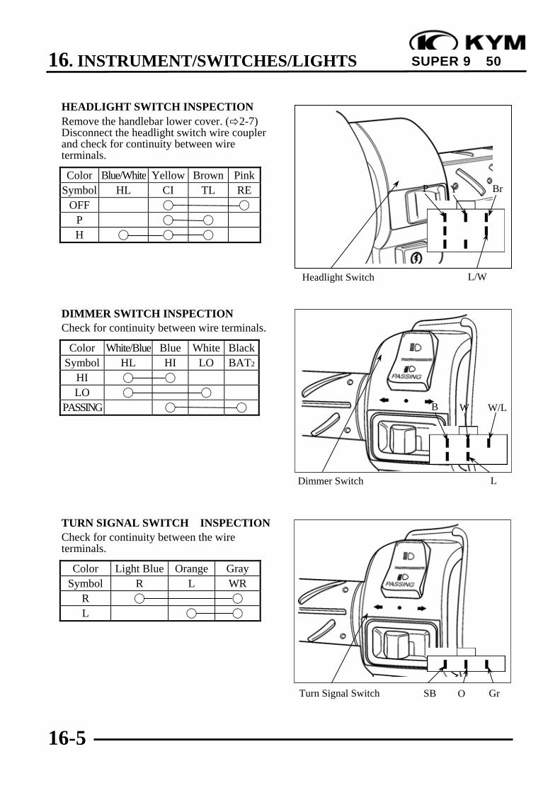
16. INSTRUMENT/SWITCHES/LIGHTS
16-5
SUPER 9 50
HEADLIGHT SWITCH INSPECTIONRemove the handlebar lower cover. ( 2-7)Disconnect the headlight switch wire couplerand check for continuity between wireterminals.
Color Blue/White Yellow Brown PinkSymbol HL CI TL RE
OFF
P
H
DIMMER SWITCH INSPECTIONCheck for continuity between wire terminals.
Color White/Blue Blue White BlackSymbol HL HI LO BAT2
HI
LO
PASSING
TURN SIGNAL SWITCH INSPECTIONCheck for continuity between the wireterminals.
Color Light Blue Orange GraySymbol R L WR
R
L
Headlight Switch
Dimmer Switch
SBTurn Signal Switch O Gr
L
WB
L/W
Y BrP
W/L

16. INSTRUMENT/SWITCHES/LIGHTS
16-6
SUPER 9 50
STARTER SWITCH INSPECTIONCheck for continuity between wire terminals.Push the starter button when measuring.
Color Yellow/Red GreenSymbol ST EFREEPUSH
HORN SWITCH INSPECTIONCheck for continuity between wire terminals.Push the horn button when measuring.
Color Light Green BlackSymbol HO BAT2
FREEPUSH
STOP SWITCH INSPECTIONRemove the handlebar lower cover. ( 2-7)Disconnect the front and rear stop switchwire couplers.Check for continuity between the wireterminals when the front/rear brake lever isapplied.
Horn Switch
B
Lg
Starter Switch Y/RG
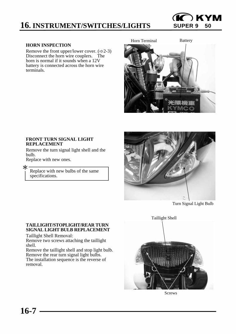
16. INSTRUMENT/SWITCHES/LIGHTS
16-7
SUPER 9 50
HORN INSPECTIONRemove the front upper/lower cover. ( 2-3)Disconnect the horn wire couplers. Thehorn is normal if it sounds when a 12Vbattery is connected across the horn wireterminals.
FRONT TURN SIGNAL LIGHTREPLACEMENTRemove the turn signal light shell and thebulb.Replace with new ones.
TAILLIGHT/STOPLIGHT/REAR TURNSIGNAL LIGHT BULB REPLACEMENTTaillight Shell Removal:Remove two screws attaching the taillightshell.Remove the taillight shell and stop light bulb.Remove the rear turn signal light bulbs.The installation sequence is the reverse ofremoval.
Taillight Shell
Screws
Turn Signal Light Bulb
Horn Terminal Battery
Replace with new bulbs of the samespecifications.
*

16. INSTRUMENT/SWITCHES/LIGHTS
16-8
SUPER 9 50
INSTRUMENTInstrument Bulbs ReplacementRemove three screws attaching theinstrument bulbs.Remove the instrument bulbs cover.Remove the bulbs and replace with new ones.
SPEEDOMETER REMOVALDisconnect the speedometer cable.Disconnect the speedometer wire connector.Remove the two screws attaching thespeedometer.Remove the speedometer.The installation sequence is the reverse ofremoval.
HEADLIGHTREMOVAL/BULB REPLACEMENTRemove the front upper/lower cover. ( 2-3)Remove the bulb sockets and bulbs.
The installation sequence is the reverse ofremoval.
Screws
• The model adopts krypton gas bulb.When installing, do not directly touchthe bulb glass with fingers.
• Use bulbs of the same specificationsfor replacement.
*
Coupler
Bulb Sockets
Wire Couplers
Bulb Sockets
17. EVAPORATIVE/EXHAUST EMISSION CONTROL SYSTEM
17-0
SUPER 9 50
17__________________________________________________________________________________
__________________________________________________________________________________
__________________________________________________________________________________
__________________________________________________________________________________
__________________________________________________________________________________
EVAPORATIVE/EXHAUST EMISSIONCONTROL SYSTEM
__________________________________________________________________________________
EXHAUST EMISSION CONTROL SYSTEM................................... 17-1
EXHAUST MUFFLER........................................................................ 17-2
EXHAUST EMISSION RELATED SYSTEM INSPECTION........... 17-3
17

17. EVAPORATIVE/EXHAUST EMISSION CONTROL SYSTEM
17-1
SUPER 9 50
EXHAUST EMISSION CONTROL SYSTEMThe exhaust emission control system adopted by this model is an oxidizing catalytic converterwhich is located in the middle of the exhaust muffler to reduce pollutants in the exhaustemission.
Exhaust Muffler Diagram
FUNCTION
Item Purpose Function
Oxidizing Catalytic Converter
Reduce the concentration ofHC and CO in the exhaustemission.
The precious metal in the oxidizing catalyticconverter is used to oxidize HC and CO inthe exhaust emission into CO2 and H2O toavoid air pollution.
TROUBLESHOOTINGEngine runs erratic at idle speed and
Lack of power and high CO & HO high fuel consumption1. Clogged exhaust muffler 1. Clogged exhaust muffler2. Faulty oxidizing catalytic converter 2. Clogged carburetor3. Carburetor adjusted improperly 3. Clogged air cleaner4. Clogged air cleaner 4. Faulty spark plug5. Faulty spark plug 5. Incorrect ignition timing6. Incorrect ignition timing
Catalytic Converter
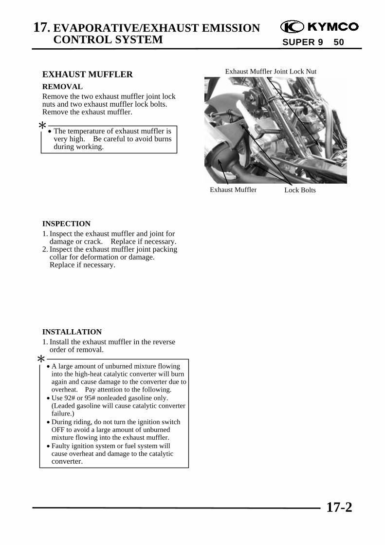
17. EVAPORATIVE/EXHAUST EMISSION CONTROL SYSTEM
17-2
SUPER 9 50
EXHAUST MUFFLERREMOVALRemove the two exhaust muffler joint locknuts and two exhaust muffler lock bolts.Remove the exhaust muffler.
INSPECTION1. Inspect the exhaust muffler and joint for
damage or crack. Replace if necessary.2. Inspect the exhaust muffler joint packing
collar for deformation or damage.Replace if necessary.
INSTALLATION1. Install the exhaust muffler in the reverse
order of removal.
• The temperature of exhaust muffler isvery high. Be careful to avoid burnsduring working.
*
Exhaust Muffler Lock Bolts
Exhaust Muffler Joint Lock Nut
•A large amount of unburned mixture flowinginto the high-heat catalytic converter will burnagain and cause damage to the converter due tooverheat. Pay attention to the following.
•Use 92# or 95# nonleaded gasoline only.(Leaded gasoline will cause catalytic converterfailure.)
•During riding, do not turn the ignition switchOFF to avoid a large amount of unburnedmixture flowing into the exhaust muffler.
• Faulty ignition system or fuel system willcause overheat and damage to the catalyticconverter.
*
17. EVAPORATIVE/EXHAUST EMISSION CONTROL SYSTEM
17-3
SUPER 9 50
EXHAUST EMISSION RELATED SYSTEM INSPECTIONClean or replace the air cleaner.Clean and adjust the carburetor.Inspect the auto bystarter system.Clean and inspect the spark plug.Inspect the ignition system.
EXHAUST EMISSION TEST AND ADJUSTMENT1. Start the engine and warm up for several minutes. (Engine surface temperature 50~60)2. Adjust the idle speed to:: SH10AD:2000±100rpm SF10DA:1900±100rpm3. Connect the emission tester sampling pipe to the exhaust muffler.
Standard:CO: 3±0.5%HC: 7000PPM max.
4. If CO or HC exceeds the specified values, adjust the carburetor air screw (A.S.) until CO and HCare within the specified standard values.A.S. Opening: SH10AD: 1¼± ½ turns ,SF10DA: 1¼± ½ turns
5. If the adjustment of carburetor makes no difference, inspect exhaust emission related system.