preface - horiba
TRANSCRIPT

I
CODE:GZ0000574030 August, 2019 2019 HORIBA Advanced Techno, Co.,
Ltd.
■PrefaceThis manual describes the operation of the following instrument.
Be sure to read this manual before using the product to ensure proper and safe operationof the product. Also, safely store the manual so it is readily available whenever necessary.Product specifications and appearance, as well as the contents of this manual are subjectto change without notice.
●Warranty and ResponsibilityHORIBA Advanced Techno Co., Ltd. warrants that the product shall be free from defects inmaterial and workmanship and agrees to repair or replace free of charge, at option ofHORIBA Advanced Techno Co., Ltd., any malfunctioned or damaged product attributableto responsibility of HORIBA Advanced Techno Co., Ltd. for a period of Three (3) years fromthe delivery unless otherwise agreed in a written statement. In any one of the followingcases, none of the warranties set forth herein shall be extended:
• Any malfunction or damage attributable to improper operation• Any malfunction attributable to repair or modification by any person not authorized by
HORIBA Advanced Techno Co., Ltd.• Any malfunction or damage attributable to the use in an environment not specified in
this manual• Any malfunction or damage attributable to violation of the instructions in this manual or
operations in the manner not specified in this manual• Any malfunction or damage attributable to any cause or causes beyond the
reasonable control of HORIBA Advanced Techno Co., Ltd. such as natural disasters• Any deterioration in appearance attributable to corrosion, rust, and so on• Replacement of consumables
HORIBA Advanced Techno Co., Ltd. SHALL NOT BE LIABLE FOR ANY DAMAGESRESULTING FROM ANY MALFUNCTIONS OF THE PRODUCT, ANY ERASURE OFDATA, OR ANY OTHER USES OF THE PRODUCT.
●TrademarksMicrosoft, Windows are registered trademarks or trademarks of Microsoft Corporation inthe United States and other countries.Other company names and brand names are either registered trademarks or trademarks ofthe respective companies. (R), (TM) symbols may be omitted in this manual.
Brand: LAQUASeries name: LAQUA WQ-300series Handheld Water Quality MeterModel: WQ-310, WQ-320, WQ-330

Regulations
II
■Regulations
●EU regulations
●Conformable DirectiveThis equipment conforms to the following directives and standards:
●Information on Disposal of Electrical and Electronic Equipment and Disposal of Batteries and AccumulatorsThe crossed out wheeled bin symbol with underbar shown on the product or accompanyingdocuments indicates the product requires appropriate treatment, collection and recycle forwaste electrical and electronic equipment (WEEE) under the Directive 2002/96/EC, and/orwaste batteries and accumulators under the Directive 2006/66/EC in the European Union.The symbol might be put with one of the chemical symbols below. In this case, itsatisfies the requirements of the Directive 2006/66/EC for the object chemical.This product should not be disposed of as unsorted household waste.Your correct disposal of WEEE, waste batteries and accumulators will contribute toreducing wasteful consumption of natural resources, and protecting human health and theenvironment from potential negative effects caused by hazardous substance in products.Contact your supplier for information on applicable disposal methods.
●Authorised representative in EU
HORIBA Europe GmbHHans-Mess-Str.6, D-61440 Oberursel, Germany
EMC: EN61326-1Class B, Basic electromagnetic environment
RoHS: EN505819. Monitoring and control instruments
Warning: This product is not intended for use in industrial environments. In an indus-trial environment, electromagnetic environment effects may cause theincorrect performance of the product in which case the user may berequired to take adequate measures.
Regulations
III
●FCC rules
●FCC Compliance StatementThis device complies with part 15 of the FCC Rules. Operation is subject to the followingtwo conditions: (1) This device may not cause harmful interference, and (2) this devicemust accept any interference received, including interference that may cause undesiredoperation. 47 CFR 15 subpart B. This product is considered an exempt device perclause §15.103/§2.1202.
Note
This equipment has been tested and found to comply with the limits for a Class A digitaldevice, pursuant to part 15 of the FCC Rules. These limits are designed to providereasonable protection against harmful interference when the equipment is operated in acommercial environment. This equipment generates, uses, and can radiate radiofrequency energy and, if not installed and used in accordance with the instructionmanual, may cause harmful interference to radio communications. Operation of thisequipment in a residential area is likely to cause harmful interference in which case theuser will be required to correct the interference at his own expense.
Any changes or modifications not expressly approved by the party responsible forcompliance could void the user's authority to operate the equipment.
Responsible Party for FCC matter
HORIBA Instruments IncorporatedHead Office9755 Research DriveIrvine, California 92618, U.S.A+1 949 250 4811
Regulations
IV
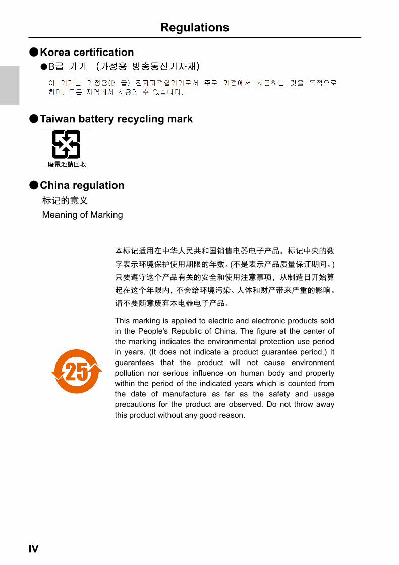
●Korea certification●
●Taiwan battery recycling mark
●China regulation
( )
This marking is applied to electric and electronic products sold in the People's Republic of China. The figure at the center of the marking indicates the environmental protection use period in years. (It does not indicate a product guarantee period.) It guarantees that the product will not cause environment pollution nor serious influence on human body and property within the period of the indicated years which is counted from the date of manufacture as far as the safety and usage precautions for the product are observed. Do not throw away this product without any good reason.
Meaning of Marking
Regulations
V
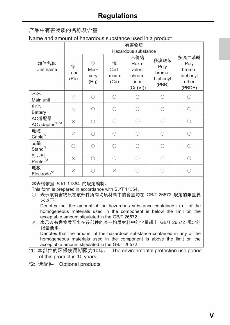
Name and amount of hazardous substance used in a product
Unit name
Hazardous substance
Lead (Pb)
Mercury (Hg)
Cad- mium(Cd)
Hexa- valent chrom-
ium(Cr (VI))
Poly
bromo- biphenyl (PBB)
Poly
bromo-diphenyl
ether (PBDE)
Main unit
Battery
ACAC adapter*1, *2
Cable*2
Stand*2
Printer*2
Electrode*2
SJ/T 11364This form is prepared in accordance with SJ/T 11364.
: GB/T 26572
Denotes that the amount of the hazardous substance contained in all of the homogeneous materials used in the component is below the limit on the acceptable amount stipulated in the GB/T 26572.
: GB/T 26572
Denotes that the amount of the hazardous substance contained in any of the homogeneous materials used in the component is above the limit on the acceptable amount stipulated in the GB/T 26572.
*1: 10 The environmental protection use period of this product is 10 years.
*2: Optional products
For Your Safety
VI
■For Your Safety
●Hazard classification and warning symbolsWarning messages are described in the following manner. Read the messages and followthe instructions carefully.
●Hazard classification
●Warning symbols
This indicates an imminently hazardous situation which, ifnot avoided, will result in death or serious injury. This is tobe limited to the most extreme situations.
This indicates a potentially hazardous situation which, ifnot avoided, could result in death or serious injury.
This indicates a potentially hazardous situation which, ifnot avoided, may result in minor or moderate injury. It mayalso be used to alert against unsafe practices.Without safety alert indication of hazardous situationwhich, if not avoided, could result in property damage.
Description of what should be done, or what should be followed
Description of what should never be done, or what is prohibited
For Your Safety
VII
●Safety precautionsThis section provides precautions for using the product safely and correctly and to preventinjury and damage. The terms of DANGER, WARNING, and CAUTION indicate the degreeof imminency and hazardous situation. Read the precautions carefully as it containsimportant safety messages.
●Instrument and Sensor
●Battery
WARNING
Do not disassemble or modify the instrument. Otherwise, it may heat up or be ignited resulting in a fire or an accident.
CAUTION
Harmful chemicalsSome electrodes are used with hazardous standard solutions. Handle them with care. The internal solution of pH electrode is highly concentrated potassium chloride (3.33 mol/L KCl). If the internal solution comes in contact with the skin, wash it off immediately. If it gets into the eyes, flush with plenty of water and then consult a doctor.
Broken glassBroken glass may cause injury. The outer tube and tip of an electrode are made of glass. Handle them with care.
Do not use the photo jack under wet or humid conditions. Otherwise, it may cause a fire, electric shock, or breakage.
WARNING
Keep batteries out of reach of children. If someone accidentally swallows a battery, consult a doctor immediately.
If alkaline fluid from a battery gets into the eyes, do not rub the eyes, rinse with clean water immediately and then consult a doctor.Contact with alkaline fluid could cause blindness.
Do not put batteries in a fire, expose to heat, disassemble or remodel.Doing so could case fluid leakage, overheating or explosion.
Product Handling Information
VIII
■Product Handling Information
●Operational precautions (instrument)• Only use the product including accessories for their intended purpose.• Do not drop or physically impact on the instrument.• The instrument is made of solvent-resistant materials but that does not mean it is
resistant to all chemicals. Do not expose the instrument in strong acid or alkalisolution, or wipe with such solution.
• If the instrument is dropped into water or gets wet, wipe it using soft cloth. Do not heatto dry it.
• The instrument has a dust-proof and waterproof structure i.e., the instrument does notmalfunction even when immersed in water of 1 m depth for 30 minutes. This doesguarantee non-destructive, trouble-free, dust-proof, and waterproof performance in allsituations.
• When replacing the batteries or when a serial cable connected, the instrument doesnot have the dust-proof and waterproof performance. The dust-proof and waterproofperformance is maintained only when the covers are attached correctly.
• After replacing the batteries or removing the serial cable connected, make sure thatthe waterproof gasket attached to the cover is not deformed or discolored, or hasforeign matter adhering to it. If the waterproof gasket is deformed, discolored or hasforeign matter adhering to it, dust could get inside, water leaks could occur that couldlead to instrument malfunction.
• To disconnect an electrode or serial cable, hold the connector and pull it off. If you pullat the cable, it may cause breakage.
• The phono jack communication between the instrument and a personal computer(referred to as PC in the rest of this document) may fail because of environmentalconditions, such as electromagnetic noise.
• Do not replace the batteries in a dusty place or with wet hands. Dust or moisture couldget inside the instrument, possibly causing instrument malfunction.
• Do not use an object with a sharp end to press the keys.• If the power supply is interrupted while measurement data is being saved in the
instrument, the data could be corrupted.• A Ni-MH rechargeable battery can be used in this instrument.

Product Handling Information
IX
●Operational precautions (battery)• Do not short circuit a battery.• Position the + and – side of the battery correctly.• When the battery has depleted or the instrument will not be used for a long time,
remove the batteries.• Of the specified battery types, make sure to use two batteries of the same type.• Do not use a new battery together with a used battery.• Do not use a fully charged nickel-metal hydride battery together with a partially
charged battery.• Do not attempt to charge a non-rechargeable battery.
●Environmental conditions for use and storage• Temperature: 0°C to 45°C• Humidity: under 80% relative humidity and free from condensation
Avoid the following conditions.• Strong vibration• Direct sunlight• Corrosive gas environment• Locations close to an air-conditioner• Direct wind
●TransportationWhen transporting the instrument, repackage it in the original package box. Otherwise, itmay cause instrument breakage.
●DisposalWhen disposing of the product, battery and standard solutions used for the calibrationfollow the related laws and regulations of your country for disposal of the product.

Contents
X
Product Overview................................................................. 1
■ Package Content .................................................................1
■ Key Features ........................................................................3
■ Product components...........................................................4
■ Display..................................................................................5
■ Keypad operation ................................................................7
Basic operations .................................................................. 8
■ Turnig on the instrument ....................................................8
■ Using the External Power Supply ......................................9
■ Connecting sensors ............................................................9
■ Operation mode .................................................................10
■ Changing the measurement parameter...........................11
■ Changing the magnifing measurement display..............11
■ Viewing Calibration data...................................................12
Calibration .......................................................................... 14
■ pH Calibration ....................................................................14
■ EC Calibration....................................................................16
■ Salinity Calibration ............................................................18
■ DO Calibration ...................................................................20
■ ION Calibration ..................................................................22
■ ORP calibration..................................................................24
■ Temperature calibration....................................................26
■ Multi auto calibration ........................................................28
Measurement ...................................................................... 30
■ measurement .....................................................................30
Contents
XI
Data ..................................................................................... 31
■ Data storage.......................................................................31
■ Data display .......................................................................31
■ Data management..............................................................32
■ Data transfer to PC ............................................................33
■ Print data ............................................................................34
Setup ................................................................................... 36
■ ID Setup ..............................................................................36
■ General Setup ....................................................................37
■ pH Setup.............................................................................39
■ COND, TDS, Sal Setup ......................................................40
■ DO Setup ............................................................................42
■ ION Setup ...........................................................................43
■ ORP Setup..........................................................................44
Maintenance and storage .................................................. 45
■ Maintenance and storage of the instrument ...................45
■ Maintenance and storage of pH and ORP sensors ........46
■ Maintenance and storage of the EC sensor....................47
■ Maintenance and storage of the DO sensor ...................48
■ Maintenance and storage of the ION sensor ..................49
Error messages and trouble shooting ............................. 50
Appendix............................................................................. 52
■ Specification ......................................................................52

Contents
XII
Package Content
1
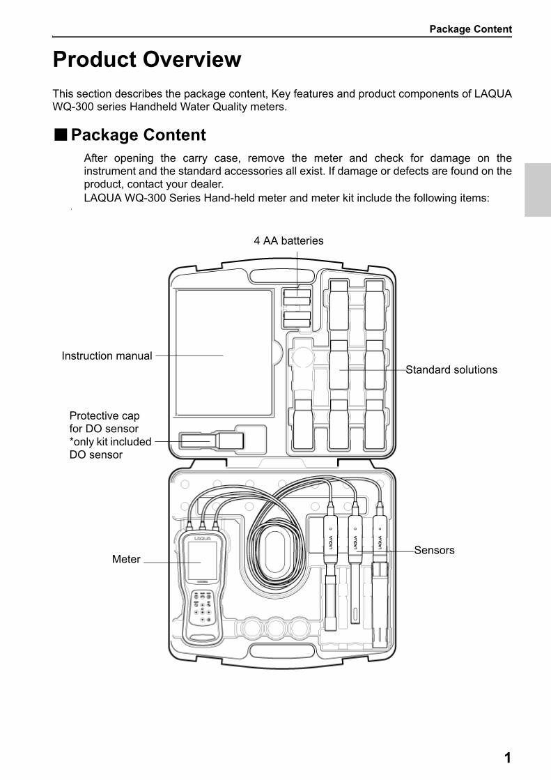
Product OverviewThis section describes the package content, Key features and product components of LAQUAWQ-300 series Handheld Water Quality meters.
■Package ContentAfter opening the carry case, remove the meter and check for damage on theinstrument and the standard accessories all exist. If damage or defects are found on theproduct, contact your dealer.LAQUA WQ-300 Series Hand-held meter and meter kit include the following items:
a
Instruction manual
4 AA batteries
Standard solutions
MeterSensors
Protective capfor DO sensor*only kit includedDO sensor

Package Content
2
Kit WQ-310PH-K WQ-310EC-K WQ-310DO-K WQ-320PC-K WQ-320PD-K WQ-330PCD-K
Meter WQ-310 : 1 Channel type ● ● ●
WQ-320 : 2 Channels type ● ●
WQ-330 : 3 Channels type ●
Sensor Head
300PH-2 : pH Sensor Head ● ● ● ●
300-C-2 : EC Sensor Head ● ● ●
Sensor Cartridge
300-P-C : Gel-filled pH Sensor Cartridge
● ● ●
300-4C-C : 4-Cell EC Sensor Cartridge
● ● ●
DO Sensor
300-D-2 : Optical DO sensor(mounted DO cap)
● ● ●
Standard Solutions
4.01, 7.00, 10.01 pH (Each 60ml) ● ● ● ●
84µS,1413µS,12.88mS &111.8mS/cm (Each 60ml)
● ● ●
Battery4 × AA Batteries
● ● ● ● ● ●
Instruction Manual
For WQ-300 series ● ● ● ● ● ●
Carry Case
For WQ-300 series ● ● ● ● ● ●
Key Features
3
■Key Features IP67 water ingress, dust-proof, shock-resistant, anti-slip meter housing. Large Color Graphic Display (70 x 55 mm) Built-in sensor holder (up to 3 sensors) Simple user interface and multi parameter display. 10,000 data memory. Automatic Temperature Compensation (ATC) with temperature sensor Auto-hold / Auto stable with stability indicator and Real-time measurement modes. Data transfer without a special software from the meter to a computer via USB
connection

Product components
4
■Product components
Meter
Display
Operation key
LED Stability indicator
Sensor Head
Sensor Cartridge
Printer portMicro USB port
Stand
Sensorholder
Wall Hanging hole
Battery Cover
1 channel type
2 channel type
3 channel type
Ch1
Ch1
Ch2
Ch 1Ch 2Ch3

Display
5
■Display
*1 Overview of Status icon area
Icon Function
Appears when a key operation is invalid.
Appears when Printer comunication is set ON.
Appears when Data logging is set ON.
Appears when data is storaged to the meter.
Displays the battery level.: Battery level 50 - 100%: Battery level 20 - 50%: Battery level less than 20% Prepare the batteries or use Power supply.: Battery has run out. Replace the batteries or use Powe supply.: Displays USB power supply in use. Batteries power is not used.
Status icons*1
Sample temperature
Main measurement value
Sub measurement value*2
(Only 1 channel display)
Sensor Status Calibration information*2
(Only 1 channel display)
Main measurement item
Stability iconHOLD icon
Connect Connect
Remove Remove
Display
6
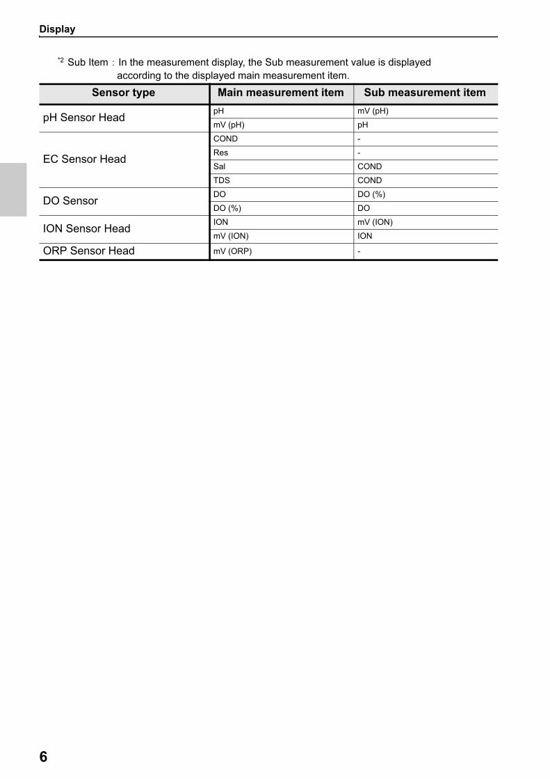
*2 Sub Item : In the measurement display, the Sub measurement value is displayed according to the displayed main measurement item.
Sensor type Main measurement item Sub measurement item
pH Sensor HeadpH mV (pH)
mV (pH) pH
EC Sensor Head
COND -
Res -
Sal COND
TDS COND
DO SensorDO DO (%)
DO (%) DO
ION Sensor HeadION mV (ION)
mV (ION) ION
ORP Sensor Head mV (ORP) -

Keypad operation
7
■Keypad operation
Keypad Name Function
CAL keySwitches from the measurement mode to the calibration mode.
MEAS keySwitches the operation mode to the measurement mode.
DATA key Switches from the measurement mode to the data mode.
MODE keyIn the measurement mode, changes measurement parameters.
SET keySwitches to the setup mode of the meter and the connected sensor.
ENT keyDetermines the selection or set up. Saves data in measurement mode and confirm calibration value in calibration mode.
UP key
Moves the focus area and switches the screen.DOWN key
LEFT key
RIGHT key
POWER key Powers ON/OFF the instrument.
Turnig on the instrument
8
Basic operationsThis section describes function and basic operation method of each part of LAQUA WQ-300series handheld Water Quality meter.
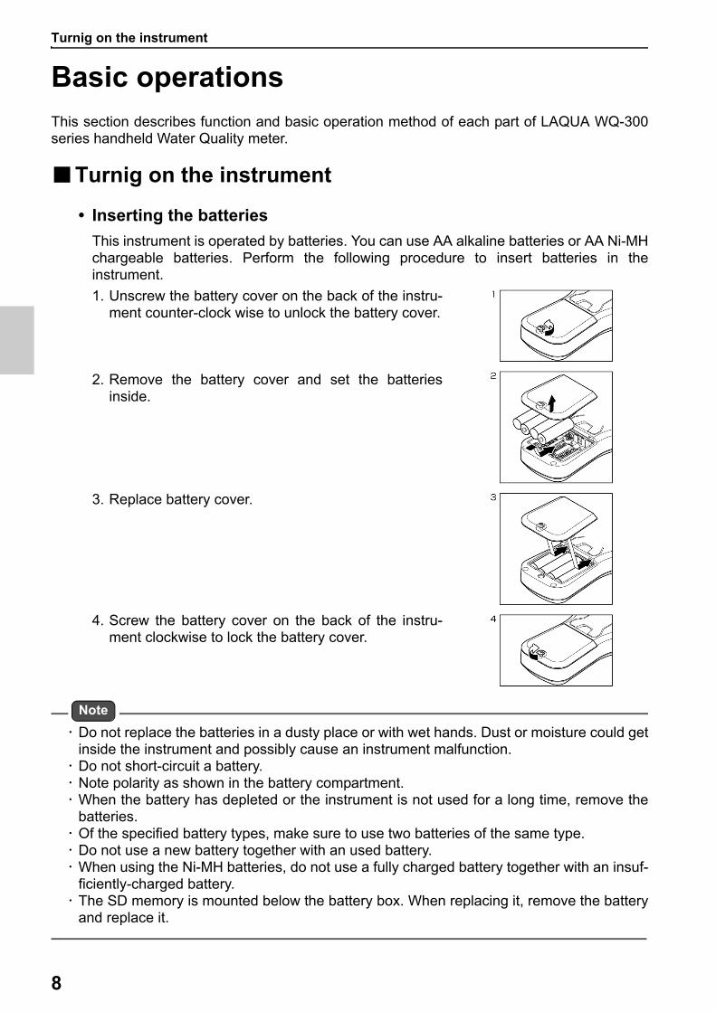
■Turnig on the instrument
• Inserting the batteries
This instrument is operated by batteries. You can use AA alkaline batteries or AA Ni-MHchargeable batteries. Perform the following procedure to insert batteries in theinstrument.
Note
Do not replace the batteries in a dusty place or with wet hands. Dust or moisture could getinside the instrument and possibly cause an instrument malfunction. Do not short-circuit a battery. Note polarity as shown in the battery compartment. When the battery has depleted or the instrument is not used for a long time, remove the
batteries. Of the specified battery types, make sure to use two batteries of the same type. Do not use a new battery together with an used battery. When using the Ni-MH batteries, do not use a fully charged battery together with an insuf-
ficiently-charged battery. The SD memory is mounted below the battery box. When replacing it, remove the battery
and replace it.
1. Unscrew the battery cover on the back of the instru-ment counter-clock wise to unlock the battery cover.
2. Remove the battery cover and set the batteriesinside.
3. Replace battery cover.
4. Screw the battery cover on the back of the instru-ment clockwise to lock the battery cover.

Using the External Power Supply
9
■Using the External Power SupplyThe Micro-USB interface can be used for external power supply. It is not possible tocharge the batteries. The instrument is not supplied with an external 5V USB battery.Alternatively, the instrument can be supplied by an external power supply unit (notincluded in the scope of delivery) via the Micro-USB socket. Use an external battery thatis suitable for 5V USB battery. For connection, a suitable USB cable with a Micro-USBplug is required. The power saving mode is canceled only when using external power.
*Power saving mode: When the power supply is only the battery, the screen brightness will automatically shift to 1 if there is no button operation for more than 1 minute. Return to the set screen brightness by key operation.
While the instrument is powered by the external power supply, the batteries are notbeing used. The icon is shown the screen.
Attention
Take care that the AC adapter does not come into contact with liquids.
■Connecting sensorsTo perform calibration/ measurement, it is necessary to use the appropriate sensors formeasurement parameter. Recommended sensors for various sample are listed below.Use the following procedure to correctly connect the sensor to the instrument
Align the arrow on the sensor connector with the groove of the meter plug and insert it.It does not matter if you plug the connector of any measurement item into the meterplug.
Measurement item
Sensor head or Sensor Sensor Cartridge or Electrode
pH pH Sensor head (300PH-2, -5) pH Sensor Cartridge (300-P-C)
Conductivity EC Sensor head (300-C-2, -5)4-Cell EC Sensor Cartridge (300-4C-C)
IONION Sensor head (300-I-2)and BNC conversion connector(300-BNC)
Ion Selective Electrode (65XXS-10C series, 5002S-10C)
ORPORP Sensor head (300-O-2)and BNC conversion connector(300-BNC)
ORP Electrode (9300-10D)
DO DO Sensor (300-D-2, -5)
Sensor connectorMeter plug
Operation mode
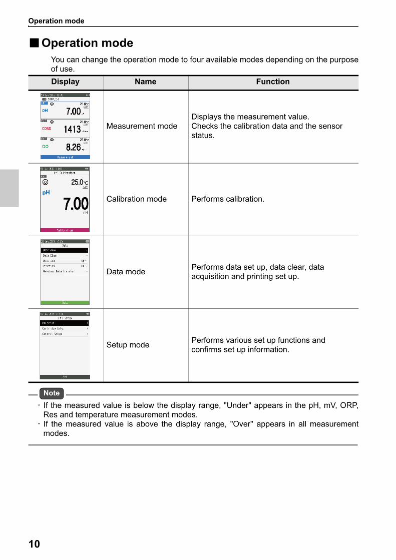
10
■Operation modeYou can change the operation mode to four available modes depending on the purposeof use.
Note
If the measured value is below the display range, "Under" appears in the pH, mV, ORP,Res and temperature measurement modes. If the measured value is above the display range, "Over" appears in all measurement
modes.
Display Name Function
Measurement modeDisplays the measurement value.Checks the calibration data and the sensor status.
Calibration mode Performs calibration.
Data modePerforms data set up, data clear, data acquisition and printing set up.
Setup modePerforms various set up functions and confirms set up information.
Changing the measurement parameter
11
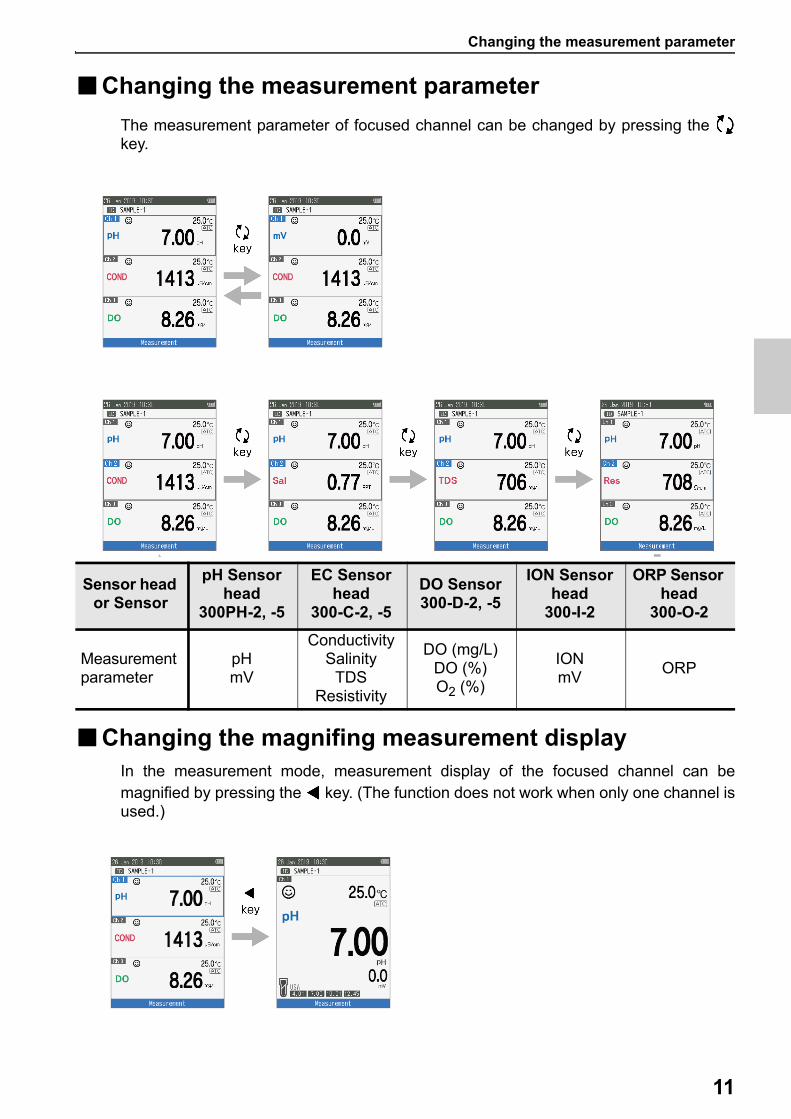
■Changing the measurement parameter
The measurement parameter of focused channel can be changed by pressing the key.
■Changing the magnifing measurement displayIn the measurement mode, measurement display of the focused channel can bemagnified by pressing the key. (The function does not work when only one channel isused.)
Sensor head or Sensor
pH Sensor head
300PH-2, -5
EC Sensor head
300-C-2, -5
DO Sensor300-D-2, -5
ION Sensor head
300-I-2
ORP Sensor head
300-O-2
Measurement parameter
pHmV
ConductivitySalinity
TDSResistivity
DO (mg/L)DO (%)O2 (%)
IONmV
ORP
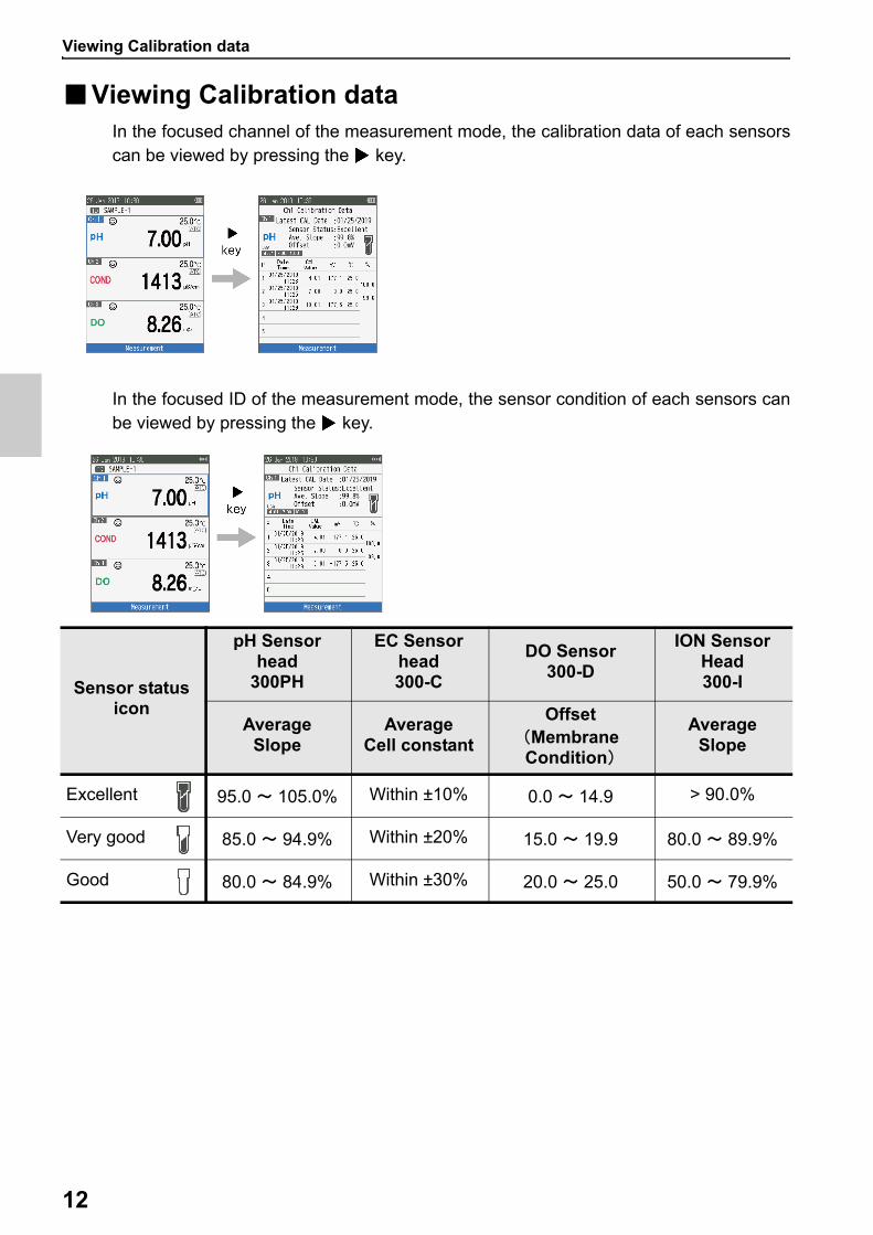
Viewing Calibration data
12
■Viewing Calibration dataIn the focused channel of the measurement mode, the calibration data of each sensorscan be viewed by pressing the key.
In the focused ID of the measurement mode, the sensor condition of each sensors canbe viewed by pressing the key.
Sensor status icon
pH Sensor head
300PH
EC Sensor head300-C
DO Sensor300-D
ION Sensor Head300-I
AverageSlope
AverageCell constant
Offset(Membrane Condition)
AverageSlope
Excellent 95.0 ~ 105.0% Within ±10% 0.0 ~ 14.9 > 90.0%
Very good 85.0 ~ 94.9% Within ±20% 15.0 ~ 19.9 80.0 ~ 89.9%
Good 80.0 ~ 84.9% Within ±30% 20.0 ~ 25.0 50.0 ~ 79.9%

Viewing Calibration data
13
pH Calibration
14
CalibrationThis section describes the basic calibration method of each measurement parameter usingLAQUA WQ-300 series and sensors (sensor head and sensor cartridge connected) or elec-trodes (ion selective electrode and BNC conversion connector connected).
■pH CalibrationCalibration is necessary for accurate pH measurement. To perform pH calibration,follow the procedure detailed below.
● Prerequisites Clean the pH sensor with DI (deionized) water and wipe it with tissue paper. Switch on the meter and plug in the pH sensor. Prepare buffer solution required for calibration. Set the Focus area in pH measurement mode. Place the pH sensor at least 3 cm in the buffer solution.
Note
Perform two-point calibration using:pH 7.00 and 4.01 for acidic samplepH 7.00 and 10.01 for alkaline sample
Perform three-point calibration using pH7.00, 4.01 and 10.01 if you are unsure of theexpected sample pH value. It is recommended to calibrate with pH7.00 first. Default buffer Group set up is USA. If you like to change to NIST, DIN, Custom refer to
“Buffer Group” on page 39.
Tip
To abort an ongoing calibration process at any point of time, press the key.
pH Calibration
15
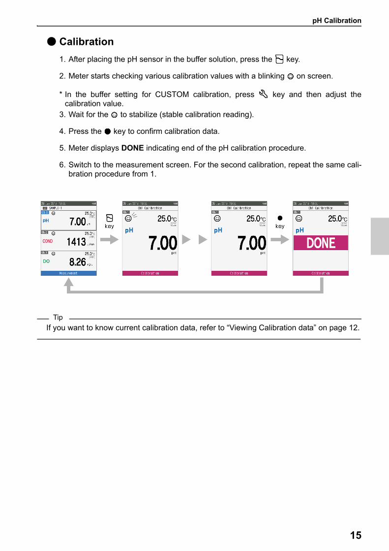
● Calibration
1. After placing the pH sensor in the buffer solution, press the key.
2. Meter starts checking various calibration values with a blinking on screen.
* In the buffer setting for CUSTOM calibration, press key and then adjust thecalibration value.
3. Wait for the to stabilize (stable calibration reading).
4. Press the key to confirm calibration data.
5. Meter displays DONE indicating end of the pH calibration procedure.
6. Switch to the measurement screen. For the second calibration, repeat the same cali-bration procedure from 1.
Tip
If you want to know current calibration data, refer to “Viewing Calibration data” on page 12.
EC Calibration
16
■EC CalibrationCalibration is necessary for accurate electrical conductivity measurement. To performconductivity calibration, follow the procedure detailed below:
● Prerequisites Clean the EC sensor with DI (deionized) water and wipe it with tissue paper. Switch on the meter and plug in the EC sensor. Prepare standard solution required for calibration. Set the Focus area in EC measurement mode. Place the EC sensor at least 3 cm in the standard solution.
Note
Salinity, TDS, and resistivity of a sample solution are calculated from the measured valueof conductivity. If you like to use manual calibration method, refer to “Cell Constant” on page 40.
Tip
For second or multiple point calibration, clean the EC sensor with DI water and follow thesame procedure. If you are performing multiple point calibration, calibrate to the lowest conductivity first and
then move to increasing conductivity values. This minimizes cross contamination. To abort an ongoing calibration process at any point of time, press the key.
EC Calibration
17
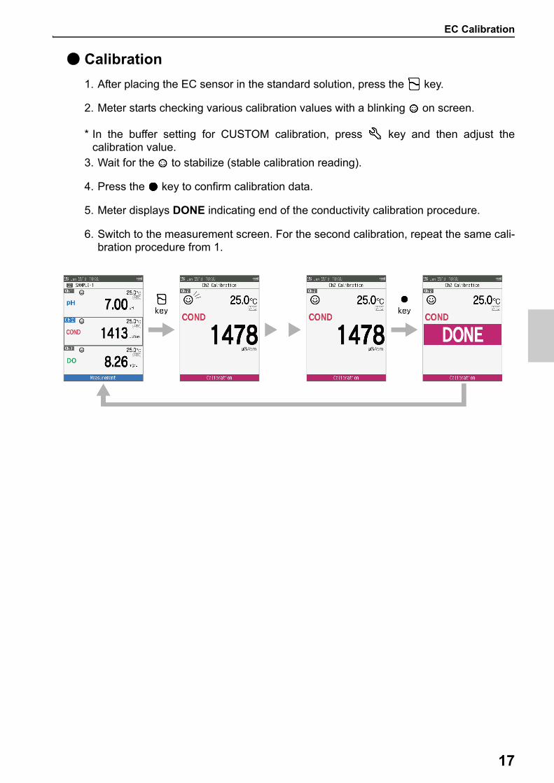
● Calibration
1. After placing the EC sensor in the standard solution, press the key.
2. Meter starts checking various calibration values with a blinking on screen.
* In the buffer setting for CUSTOM calibration, press key and then adjust thecalibration value.
3. Wait for the to stabilize (stable calibration reading).
4. Press the key to confirm calibration data.
5. Meter displays DONE indicating end of the conductivity calibration procedure.
6. Switch to the measurement screen. For the second calibration, repeat the same cali-bration procedure from 1.

Salinity Calibration
18
■Salinity CalibrationCalibration is necessary for accurate Salinity measurement. To perform salinitycalibration, follow the procedure detailed below:
● Prerequisites Clean the EC sensor with DI (deionized) water and wipe it with tissue paper. Switch on the meter and plug in the EC sensor. Prepare standard solution required for calibration. Set the Focus area in EC measurement mode.
Press the key to keep the meter in Sal mode. Place the EC sensor at least 3 cm in the standard solution.
Note
Before salinity calibration, set the required Salinity method. In LAQUA WQ-300 serieshandheld Water Quality meter, available salinity methods are; NaCl (non-linear salinity curve) Seawater (Practical Salinity Scale 1978 UNESCO) To set a desired Salinity method, refer to “Sal Type” on page 41.
Tip
To abort an ongoing calibration process at any point of time, press the key.
Salinity Calibration
19
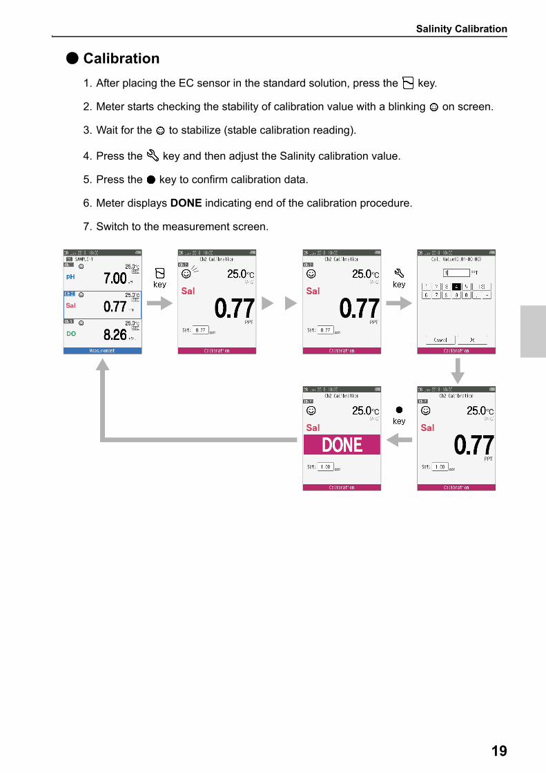
● Calibration
1. After placing the EC sensor in the standard solution, press the key.
2. Meter starts checking the stability of calibration value with a blinking on screen.
3. Wait for the to stabilize (stable calibration reading).
4. Press the key and then adjust the Salinity calibration value.
5. Press the key to confirm calibration data.
6. Meter displays DONE indicating end of the calibration procedure.
7. Switch to the measurement screen.
DO Calibration
20
■DO CalibrationCalibration is necessary for accurate DO measurement. Two calibration modes areavailable in DO meter for calibration, DO concentration mode (mg/L) DO saturation mode (%)
To perform DO calibration, follow the procedure detailed below:
● Prerequisites Clean the membrane at the tip of the DO sensor with DI (deionized) water and wipe it
with tissue paper. Switch on the meter and plug in the DO sensor. Set the Focus area in DO measurement mode.
Press the key to keep the meter in DO concentration (mg/L) or DO saturation (%)mode.
Note
High [100 %] calibration are available to calibrate in water vapor-saturated air with acalibration bottle or in air-saturated water. The sponge in the calibration bottle must be moist. Prepare Low [0 %] calibration solution by adding 2 g sodium sulfite (Na2SO3) to 1000 mL
deionized water and stirring the mixture to completely dissolve it.
Tip
To abort an ongoing calibration process at any point of time, press the key.
DO Calibration
21
● Calibration
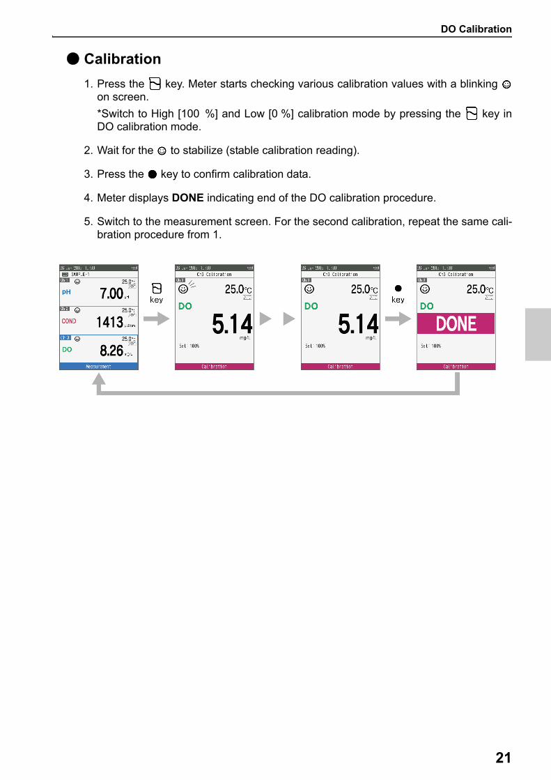
1. Press the key. Meter starts checking various calibration values with a blinking on screen.
*Switch to High [100 %] and Low [0 %] calibration mode by pressing the key inDO calibration mode.
2. Wait for the to stabilize (stable calibration reading).
3. Press the key to confirm calibration data.
4. Meter displays DONE indicating end of the DO calibration procedure.
5. Switch to the measurement screen. For the second calibration, repeat the same cali-bration procedure from 1.
ION Calibration
22
■ ION CalibrationCalibration is necessary for accurate ION measurement. To perform ION calibration,follow the procedure detailed below:
● Prerequisites Clean the senor with DI (deionized) water and wipe it with tissue paper. Switch on the meter and plug in the sensor. Prepare standard solution required for calibration. Press the key to keep the Focus area in ION measurement mode. Place the sensor at least 3 cm in the standard solution.
Note
Before ION calibration, set the required ION species. In LAQUA WQ-300 series handheldWater Quality meter, available ion species are;
K+, Ca2+, F-, NO3-, Cl-, NH3 and Custom (Ion valency:+1, +2, -1, -2)
To set ION species, refer “ION Setup” on page 43.
Tip
For second or multiple point calibration, clean the ION sensor with DI water and follow thesame procedure. If you are performing multiple point calibration, calibrate to the lowest concentration first
and then move to increasing ion values. This minimizes cross contamination. To abort an ongoing calibration process at any point of time, press the key.
ION Calibration
23
● Calibration
1. After placing the sensor in the standard solution, press the key.
2. Meter starts checking the stability of calibration value with a blinking on screen.
3. Wait for the to stabilize (stable calibration reading).
4. Press the key and then adjust the calibration value.
5. Press the key to confirm calibration data.
6. Meter displays DONE indicating end of the calibration procedure.
7. Switch to the measurement screen.
ORP calibration
24
■ORP calibrationCalibration is necessary for accurate ORP measurement. To perform salinity calibration,follow the procedure detailed below:
● Prerequisites Clean the sensor with DI (deionized) water and wipe it with tissue paper. Switch on the meter and plug in the ORP sensor. Prepare standard solution required for calibration. Set the Focus area in ORP measurement mode. Place the sensor at least 3 cm in the standard solution.
Tip
To abort an ongoing calibration process at any point of time, press the key.
ORP calibration
25
● Calibration
1. After placing the sensor in the standard solution, press the key.
2. Meter starts checking the stability of calibration value with a blinking on screen.
3. Wait for the to stabilize (stable calibration reading).
4. Press the key and then adjust the ORP calibration value.
5. Press the key to confirm calibration data.
6. Meter displays DONE indicating end of the calibration procedure.
7. Switch to the measurement screen.

Temperature calibration
26
■Temperature calibrationTemperature calibration is required to accurately match the sensor to the meter. Checkthe temperature reading and if its acceptable, no temperature calibration is required. Ifyou need to calibrate, please follow the procedure detailed below:
● Prerequisites Clean the sensor with DI (deionized) water and wipe it with tissue paper. Switch on the meter and plug in the sensor. Prepare standard solution required for calibration. Set the Focus area in the measurement mode that the temperature is needed. Place the sensor at least 3 cm in the standard solution. Wait for 5 minutes to ensure temperature stability.
Note
In the only ATC setting, temperature calibration is available. Temperature calibration must be performed using a known temperature solution or
against a calibrated thermometer.
Tip
To abort an ongoing calibration process at any point of time, press the key.

Temperature calibration
27
● Calibration
1. After placing the sensor in the standard solution, press the key.
2. Press the key to switch to temperature calibration mode. Meter displays mea-sured temperature value.
3. Press the key to adjust the calibration value.
4. Press the key to confirm calibration data.
5. Meter displays DONE indicating end of the temperature calibration procedure.
6. Switch to the measurement screen.

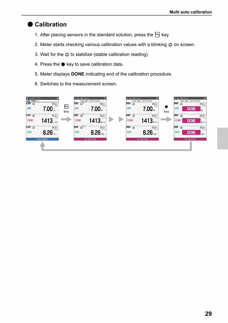
Multi auto calibration
28
■Multi auto calibrationMulti auto calibration is available with pH, EC and DO sensors in the auto calibrationsetting. If you need to calibrate, please follow the procedure detailed below:
● Prerequisites Clean the sensor with DI (deionized) water and wipe it with tissue paper. Switch on the meter and plug in sensors. Prepare standard solution required for each calibration. Set the focus area in the ID. Place the sensor at least 3 cm in the standard solution.
Note
Multi auto calibration is not available with pH and EC sensors in the Custom calibrationsetting. Multi auto calibration is not available with ION and ORP sensors, because the calibration
setting is only custom setting. DO calibration is available only High concentration calibration [100%] for the multi auto
calibration.
Tip
To abort an ongoing calibration process at any point of time, press the key.
Multi auto calibration
29
● Calibration
1. After placing sensors in the standard solution, press the key.
2. Meter starts checking various calibration values with a blinking on screen.
3. Wait for the to stabilize (stable calibration reading).
4. Press the key to save calibration data.
5. Meter displays DONE indicating end of the calibration procedure.
6. Switches to the measurement screen.
measurement
30
MeasurementThis section describes the basic measurement method of each measurement parameter usingLAQUA WQ-300 series and sensors (sensor head and sensor cartridge connected) or elec-trodes (ion selective electrode and BNC conversion connector connected).
■measurementIn measurement mode, measurement can be performed by immersing the sensor in thesample.
● Prerequisites Set the measurement type: auto-stable (Default setting), auto-hold, and real time
measurement. refer “Stability Mode” on page 37. Set the stability criteria: refer “Auto Save / Print” on page 37. Refer to “Data Log” on page 32 when using the data log function. Place the pH sensor at least 3 cm in the buffer solution.
● Sample measurement
1. Clean the sensor with DI (deionized) water and wipe it with tissue paper.
2. Open the internal liquid replacement port if the electrode has the internal liquidreplacement port.(Only Ion Selective electrode and ORP electrode.)In order for the internal solution to flow into the standard solution, make sure to Openthe internal liquid replacement port.
3. Place the sensor or the electrode at least 3 cm in the buffer solution.Refer “Calibration” on page 14 before starting sample measurement.
Data storage
31
DataThis section describes the basic method of data storing and transferring using LAQUA WQ-300series handheld Water Quality meters.
■Data storageIn LAQUA WQ-300 series handheld water quality meters, data measured by theinstrument can be stored in the internal memory.To save the measured data; Press the Key to save the displayed data.Data can be saved automatically at set time intervals. While using this function, theautomatic power OFF setting is invalid. If the battery runs out during data logging, thedata until the battery runs out is saved. Replace the battery and check the data.Refer to “Data Log” on page 32 for details on this function
Note
If the data storage limit reaches 10,000, storage data excess error message is displayed. In such case, transfer necessary data to a PC and delete the data from the internal
memory of the instrument.
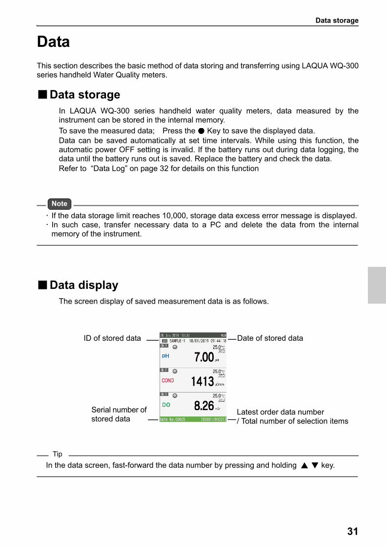
■Data displayThe screen display of saved measurement data is as follows.
Tip
In the data screen, fast-forward the data number by pressing and holding key.
Date of stored data
Serial number of stored data
ID of stored data
Latest order data number/ Total number of selection items
Data management
32
■Data management
To view, erase stored data and set data acquisition, press key.In the Data mode, move the focus with the key, select the Data View or DataClear, and press the key.
Default settings are in Bold.
*1 ... FlashAirTM is a trademark of Toshiba Corporation
Parameter Item or settings Function
Data View All Displays all stored data.
Date Displays stored data of each date.
ID Displays stored data of each ID.
Data Clear Latest Data Erase only the stored latest data.
Date Erase stored data collectively by date.
ID Erase stored data collectively by ID.
All Erase all stored data at once.
Data Log 0 (OFF)-3600 secSave measurement data to the meter according to the entered time of data log interval time.
Printing OFF ON
Turn on function to printout the data when the printer is connected to meter.
Wireless Data Transfer
Transfer stored data to PC with the product installed the FlashAirTM*1 application software or web browser (http://flashair/).Select this parameter. Since wireless connection is possible, select " flashair_ " on the device to which you want to transfer data.*The default password for wireless LAN connection is "12345678".The stored data for each channel is saved in CSV data format in User / MEAS / CH.Copy the data to the connected device.**To save battery power, exit this function immediately after data transfer.
Data transfer to PC
33
■Data transfer to PCConnect the meter to a PC using the micro-USB plug to USB cable to transfer saveddata to the PC. If you need to transfer data from meter to PC, please follow theprocedure detailed below:
For wireless data transfer, refer “Wireless Data Transfer” on page 32
● Prerequisitesprepare USB-A to micro-USB (B) interface cable
Note
Do not use USB-A to micro-USB (B) cable for only power supply. Use it for data transfer.
● Data transfer to PC
1. Turn off the meter if the meter power is on.
2. Open the cover for the micro USB and printer ports.
3. Connect the USB cable first to the meter and then to the PC.
4. Turn on the power to the meter.
5. Select OK and press key when displays Confirmation dialog for MSC (Mass Stor-age Class) mode connection.
6. Stored data for each channel is stored in CSV format in User / MEAS/ CH on the PC.Copy and paste the data of User folder in the meter to PC.*Files in the User folder should only be copied and should not be deleted or edited.Data may be lost.
Tip
During the USB communication, the meter does not have the dust-proof and waterproofperformance. The dust-proof and waterproof performance is maintained only when thecovers are attached correctly.
● Eject from PC
1. To avoid losing data, remove the USB cable safety refer to safety removing hardwareprocedure for your PC.
2. Remove the USB cable from the meter.
3. Close the cover for the micro USB and printer ports correctly.
Print data
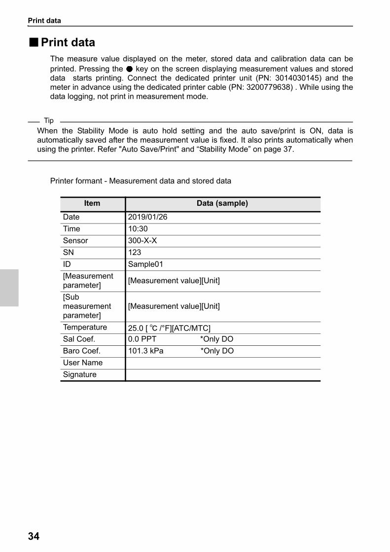
34
■Print dataThe measure value displayed on the meter, stored data and calibration data can beprinted. Pressing the key on the screen displaying measurement values and storeddata starts printing. Connect the dedicated printer unit (PN: 3014030145) and themeter in advance using the dedicated printer cable (PN: 3200779638) . While using thedata logging, not print in measurement mode.
Tip
When the Stability Mode is auto hold setting and the auto save/print is ON, data isautomatically saved after the measurement value is fixed. It also prints automatically whenusing the printer. Refer "Auto Save/Print" and “Stability Mode” on page 37.
Printer formant - Measurement data and stored data
Item Data (sample)
Date 2019/01/26
Time 10:30
Sensor 300-X-X
SN 123
ID Sample01
[Measurement parameter]
[Measurement value][Unit]
[Sub measurement parameter]
[Measurement value][Unit]
Temperature 25.0 [ ℃ /°F][ATC/MTC]Sal Coef. 0.0 PPT *Only DO
Baro Coef. 101.3 kPa *Only DO
User Name
Signature
Print data
35
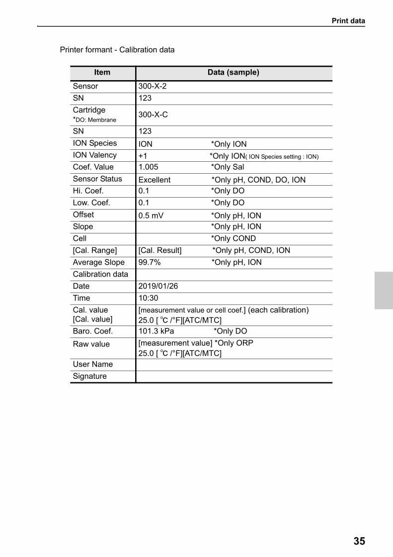
Printer formant - Calibration data
Item Data (sample)
Sensor 300-X-2
SN 123
Cartridge*DO: Membrane
300-X-C
SN 123
ION Species ION *Only IONION Valency +1 *Only ION( ION Species setting : ION)
Coef. Value 1.005 *Only Sal
Sensor Status Excellent *Only pH, COND, DO, IONHi. Coef. 0.1 *Only DO
Low. Coef. 0.1 *Only DO
Offset 0.5 mV *Only pH, IONSlope *Only pH, ION
Cell *Only COND
[Cal. Range] [Cal. Result] *Only pH, COND, ION
Average Slope 99.7% *Only pH, ION
Calibration data
Date 2019/01/26
Time 10:30
Cal. value[Cal. value]
[measurement value or cell coef.] (each calibration)25.0 [ ℃ /°F][ATC/MTC]
Baro. Coef. 101.3 kPa *Only DO
Raw value [measurement value] *Only ORP25.0 [ ℃ /°F][ATC/MTC]
User Name
Signature
ID Setup
36
SetupThis section describes all the setup functions for each measurement parameter available inLAQUA WQ-300 series handheld Water Quality meters.
■ ID SetupIndividually created ID can be selected according to the purpose of the measurement.In measurement mode, set the focus area in the ID and press the key.
Parameter Details
Select IDSelect registered ID.Default: blank
Create New IDEnter an ID using the alphanumeric entry screen (up to 8 characters and up to 100 IDs)
Delete ID Erase registered ID.
General Setup
37
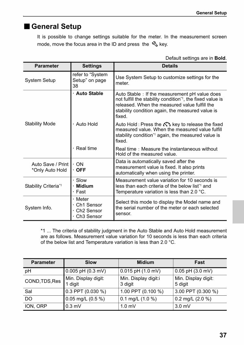
■General SetupIt is possible to change settings suitable for the meter. In the measurement screen
mode, move the focus area in the ID and press the key.
Default settings are in Bold.
*1 ... The criteria of stability judgment in the Auto Stable and Auto Hold measurementare as follows. Measurement value variation for 10 seconds is less than each criteriaof the below list and Temperature variation is less than 2.0 °C.
Parameter Settings Details
System Setuprefer to “System Setup” on page 38
Use System Setup to customize settings for the meter.
Stability Mode
Auto Stable Auto Stable : If the measurement pH value does not fulfill the stability condition*1, the fixed value is released. When the measured value fulfill the stability condition again, the measured value is fixed.
Auto Hold Auto Hold:Press the key to release the fixed measured value. When the measured value fulfill stability condition*1 again, the measured value is fixed.
Real time Real time : Measure the instantaneous without Hold of the measured value.
Auto Save / Print *Only Auto Hold
ON OFF
Data is automatically saved after the measurement value is fixed. It also prints automatically when using the printer.
Stability Criteria*1
Slow Midium Fast
Measurement value variation for 10 seconds is less than each criteria of the below list*1 and Temperature variation is less than 2.0 °C.
System Info.
Meter Ch1 Sensor Ch2 Sensor Ch3 Sensor
Select this mode to display the Model name and the serial number of the meter or each selected sensor.
Parameter Slow Midium Fast
pH 0.005 pH (0.3 mV) 0.015 pH (1.0 mV) 0.05 pH (3.0 mV)
COND,TDS,ResMin. Display digit:1 digit
Min. Display digit:i3 digit
Min. Display digit:5 digit
Sal 0.3 PPT (0.030 %) 1.00 PPT (0.100 %) 3.00 PPT (0.300 %)
DO 0.05 mg/L (0.5 %) 0.1 mg/L (1.0 %) 0.2 mg/L (2.0 %)
ION, ORP 0.3 mV 1.0 mV 3.0 mV
General Setup
38
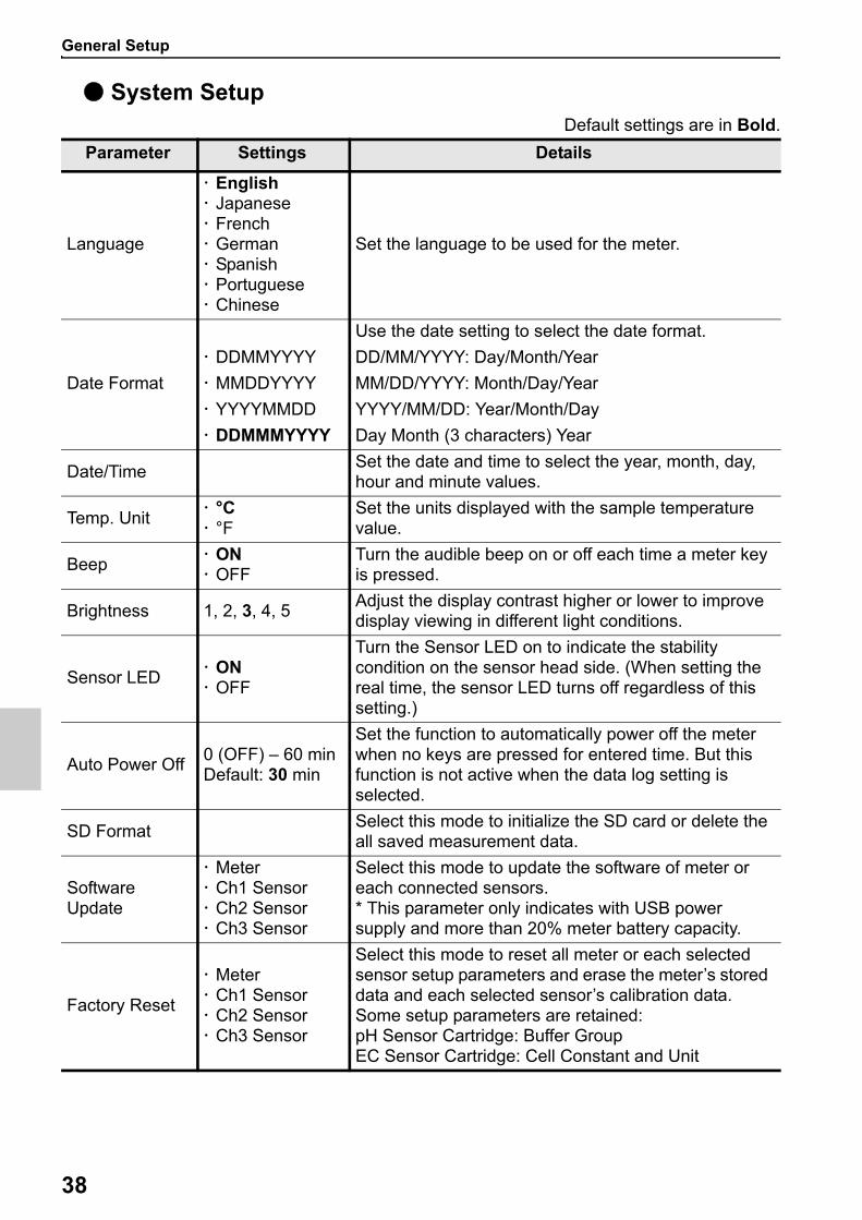
● System SetupDefault settings are in Bold.
Parameter Settings Details
Language
English Japanese French German Spanish Portuguese Chinese
Set the language to be used for the meter.
Date Format
Use the date setting to select the date format.
DDMMYYYY DD/MM/YYYY: Day/Month/Year
MMDDYYYY MM/DD/YYYY: Month/Day/Year
YYYYMMDD YYYY/MM/DD: Year/Month/Day
DDMMMYYYY Day Month (3 characters) Year
Date/TimeSet the date and time to select the year, month, day, hour and minute values.
Temp. Unit °C °F
Set the units displayed with the sample temperature value.
Beep ON OFF
Turn the audible beep on or off each time a meter key is pressed.
Brightness 1, 2, 3, 4, 5Adjust the display contrast higher or lower to improve display viewing in different light conditions.
Sensor LED ON OFF
Turn the Sensor LED on to indicate the stability condition on the sensor head side. (When setting the real time, the sensor LED turns off regardless of this setting.)
Auto Power Off0 (OFF) – 60 minDefault: 30 min
Set the function to automatically power off the meter when no keys are pressed for entered time. But this function is not active when the data log setting is selected.
SD FormatSelect this mode to initialize the SD card or delete the all saved measurement data.
Software Update
Meter Ch1 Sensor Ch2 Sensor Ch3 Sensor
Select this mode to update the software of meter or each connected sensors.* This parameter only indicates with USB power supply and more than 20% meter battery capacity.
Factory Reset
Meter Ch1 Sensor Ch2 Sensor Ch3 Sensor
Select this mode to reset all meter or each selected sensor setup parameters and erase the meter’s stored data and each selected sensor’s calibration data.Some setup parameters are retained:pH Sensor Cartridge: Buffer GroupEC Sensor Cartridge: Cell Constant and Unit
pH Setup
39
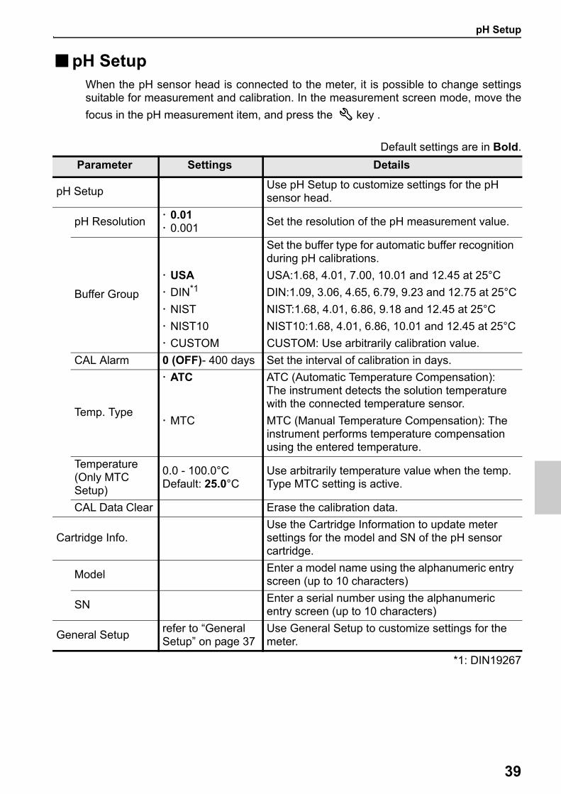
■pH SetupWhen the pH sensor head is connected to the meter, it is possible to change settingssuitable for measurement and calibration. In the measurement screen mode, move the
focus in the pH measurement item, and press the key .
Default settings are in Bold.
*1: DIN19267
Parameter Settings Details
pH SetupUse pH Setup to customize settings for the pH sensor head.
pH Resolution 0.01 0.001
Set the resolution of the pH measurement value.
Buffer Group
Set the buffer type for automatic buffer recognition during pH calibrations.
USA USA:1.68, 4.01, 7.00, 10.01 and 12.45 at 25°C
DIN*1 DIN:1.09, 3.06, 4.65, 6.79, 9.23 and 12.75 at 25°C
NIST NIST:1.68, 4.01, 6.86, 9.18 and 12.45 at 25°C
NIST10 NIST10:1.68, 4.01, 6.86, 10.01 and 12.45 at 25°C
CUSTOM CUSTOM: Use arbitrarily calibration value.
CAL Alarm 0 (OFF)- 400 days Set the interval of calibration in days.
Temp. Type
ATC ATC (Automatic Temperature Compensation): The instrument detects the solution temperature with the connected temperature sensor.
MTC MTC (Manual Temperature Compensation): The instrument performs temperature compensation using the entered temperature.
Temperature (Only MTC Setup)
0.0 - 100.0°CDefault: 25.0°C
Use arbitrarily temperature value when the temp. Type MTC setting is active.
CAL Data Clear Erase the calibration data.
Cartridge Info.Use the Cartridge Information to update meter settings for the model and SN of the pH sensor cartridge.
ModelEnter a model name using the alphanumeric entry screen (up to 10 characters)
SNEnter a serial number using the alphanumeric entry screen (up to 10 characters)
General Setuprefer to “General Setup” on page 37
Use General Setup to customize settings for the meter.
COND, TDS, Sal Setup
40
■COND, TDS, Sal SetupWhen the EC sensor head is connected to the meter, it is possible to change settingssuitable for measurement and calibration. In the measurement screen mode, move the
focus in the EC measurement item, and press the key .
Default settings are in Bold.
Parameter Settings Details
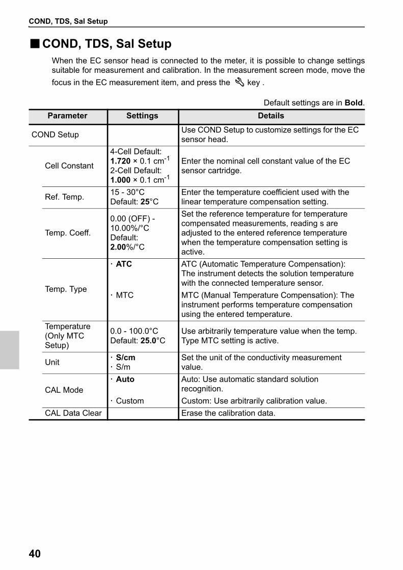
COND SetupUse COND Setup to customize settings for the EC sensor head.
Cell Constant
4-Cell Default:1.720 × 0.1 cm-1
2-Cell Default: 1.000 × 0.1 cm-1
Enter the nominal cell constant value of the EC sensor cartridge.
Ref. Temp.15 - 30°CDefault: 25°C
Enter the temperature coefficient used with the linear temperature compensation setting.
Temp. Coeff.
0.00 (OFF) - 10.00%/°CDefault: 2.00%/°C
Set the reference temperature for temperature compensated measurements, reading s are adjusted to the entered reference temperature when the temperature compensation setting is active.
Temp. Type
ATC ATC (Automatic Temperature Compensation): The instrument detects the solution temperature with the connected temperature sensor.
MTC MTC (Manual Temperature Compensation): The instrument performs temperature compensation using the entered temperature.
Temperature (Only MTC Setup)
0.0 - 100.0°CDefault: 25.0°C
Use arbitrarily temperature value when the temp. Type MTC setting is active.
Unit S/cm S/m
Set the unit of the conductivity measurement value.
CAL Mode Auto Auto: Use automatic standard solution
recognition.
Custom Custom: Use arbitrarily calibration value.
CAL Data Clear Erase the calibration data.
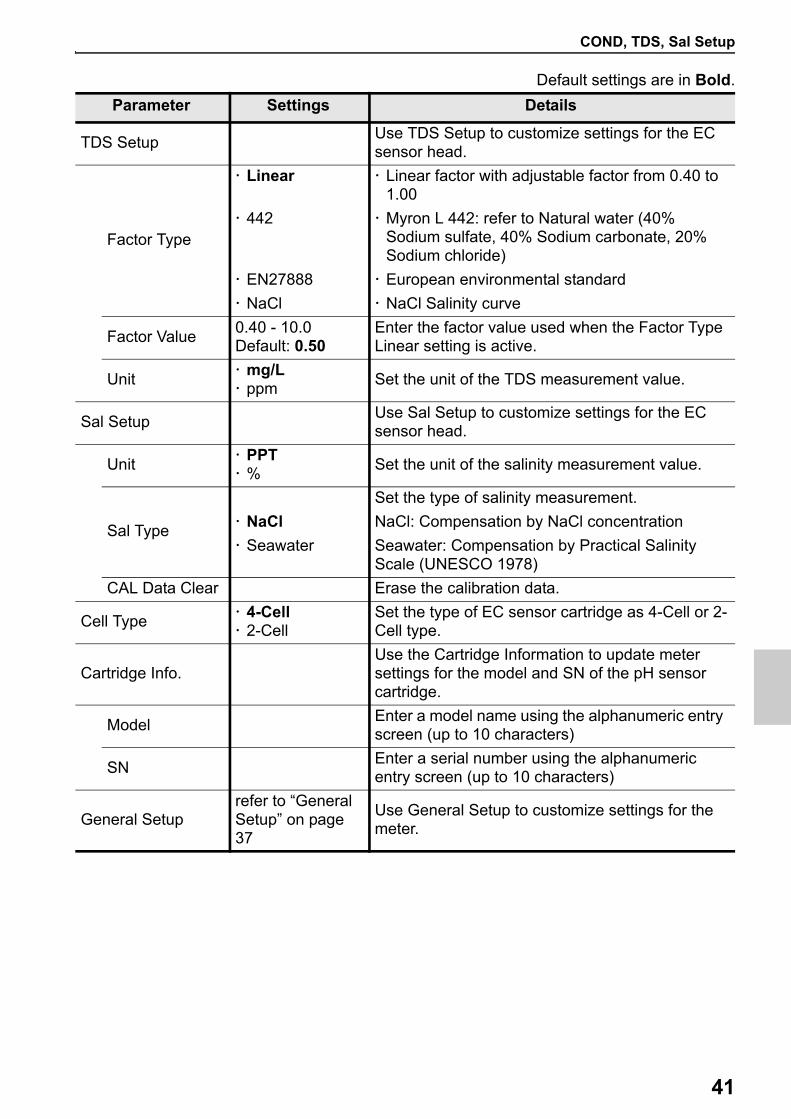
COND, TDS, Sal Setup
41
Default settings are in Bold.
Parameter Settings Details
TDS SetupUse TDS Setup to customize settings for the EC sensor head.
Factor Type
Linear Linear factor with adjustable factor from 0.40 to 1.00
442 Myron L 442: refer to Natural water (40% Sodium sulfate, 40% Sodium carbonate, 20% Sodium chloride)
EN27888 European environmental standard
NaCl NaCl Salinity curve
Factor Value0.40 - 10.0Default: 0.50
Enter the factor value used when the Factor Type Linear setting is active.
Unit mg/L ppm
Set the unit of the TDS measurement value.
Sal SetupUse Sal Setup to customize settings for the EC sensor head.
Unit PPT %
Set the unit of the salinity measurement value.
Sal Type
Set the type of salinity measurement.
NaCl NaCl: Compensation by NaCl concentration
Seawater Seawater: Compensation by Practical Salinity Scale (UNESCO 1978)
CAL Data Clear Erase the calibration data.
Cell Type 4-Cell 2-Cell
Set the type of EC sensor cartridge as 4-Cell or 2-Cell type.
Cartridge Info.Use the Cartridge Information to update meter settings for the model and SN of the pH sensor cartridge.
ModelEnter a model name using the alphanumeric entry screen (up to 10 characters)
SNEnter a serial number using the alphanumeric entry screen (up to 10 characters)
General Setuprefer to “General Setup” on page 37
Use General Setup to customize settings for the meter.
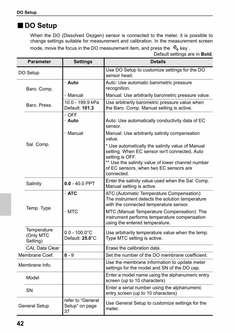
DO Setup
42
■DO SetupWhen the DO (Dissolved Oxygen) sensor is connected to the meter, it is possible tochange settings suitable for measurement and calibration. In the measurement screen
mode, move the focus in the DO measurement item, and press the key .Default settings are in Bold.
Parameter Settings Details
DO SetupUse DO Setup to customize settings for the DO sensor head.
Baro. Comp. Auto Auto: Use automatic barometric pressure
recognition.
Manual Manual: Use arbitrarily barometric pressure value.
Baro. Press.10.0 - 199.9 kPaDefault: 101.3
Use arbitrarily barometric pressure value when the Baro. Comp. Manual setting is active.
Sal. Comp.
OFF Auto Auto: Use automatically conductivity data of EC
sensor.
Manual Manual: Use arbitrarily salinity compensation value.
* Use automatically the salinity value of Manual setting. When EC sensor isn't connected, Auto setting is OFF.** Use the salinity value of lower channel number of EC sensors, when two EC sensors are connected.
Salinity 0.0 - 40.0 PPTEnter the salinity value used when the Sal. Comp. Manual setting is active.
Temp. Type
ATC ATC (Automatic Temperature Compensation): The instrument detects the solution temperature with the connected temperature sensor.
MTC MTC (Manual Temperature Compensation): The instrument performs temperature compensation using the entered temperature.
Temperature (Only MTC Setting)
0.0 - 100.0°CDefault: 25.0°C
Use arbitrarily temperature value when the temp. Type MTC setting is active.
CAL Data Clear Erase the calibration data.
Membrane Coef. 0 - 9 Set the number of the DO membrane coefficient.
Membrane Info.Use the membrane information to update meter settings for the model and SN of the DO cap.
ModelEnter a model name using the alphanumeric entry screen (up to 10 characters)
SNEnter a serial number using the alphanumeric entry screen (up to 10 characters)
General Setuprefer to “General Setup” on page 37
Use General Setup to customize settings for the meter.
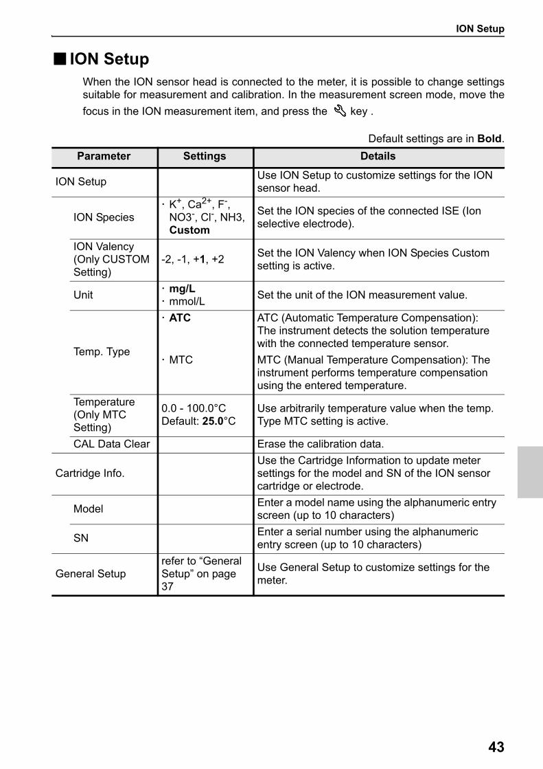
ION Setup
43
■ ION SetupWhen the ION sensor head is connected to the meter, it is possible to change settingssuitable for measurement and calibration. In the measurement screen mode, move the
focus in the ION measurement item, and press the key .
Default settings are in Bold.
Parameter Settings Details
ION SetupUse ION Setup to customize settings for the ION sensor head.
ION Species K+, Ca2+, F-,
NO3-, Cl-, NH3, Custom
Set the ION species of the connected ISE (Ion selective electrode).
ION Valency (Only CUSTOM Setting)
-2, -1, +1, +2Set the ION Valency when ION Species Custom setting is active.
Unit mg/L mmol/L
Set the unit of the ION measurement value.
Temp. Type
ATC ATC (Automatic Temperature Compensation): The instrument detects the solution temperature with the connected temperature sensor.
MTC MTC (Manual Temperature Compensation): The instrument performs temperature compensation using the entered temperature.
Temperature (Only MTC Setting)
0.0 - 100.0°CDefault: 25.0°C
Use arbitrarily temperature value when the temp. Type MTC setting is active.
CAL Data Clear Erase the calibration data.
Cartridge Info.Use the Cartridge Information to update meter settings for the model and SN of the ION sensor cartridge or electrode.
ModelEnter a model name using the alphanumeric entry screen (up to 10 characters)
SNEnter a serial number using the alphanumeric entry screen (up to 10 characters)
General Setuprefer to “General Setup” on page 37
Use General Setup to customize settings for the meter.

ORP Setup
44
■ORP SetupWhen the ORP sensor head is connected to the meter, it is possible to change settingssuitable for measurement and calibration. In the measurement screen mode, move the
focus in the ORP measurement item, and press the key .
Default settings are in Bold.
Parameter Settings Details
ORP SetupUse ORP Setup to customize settings for the ORP sensor head.
Temp. Type
ATC ATC (Automatic Temperature Compensation): The instrument detects the solution temperature with the connected temperature sensor.
MTC MTC (Manual Temperature Compensation): The instrument performs temperature compensation using the entered temperature.
Temperature (Only MTC Setting)
0.0 - 100.0°CDefault: 25.0°C
Use arbitrarily temperature value when the temp. Type MTC setting is active.
CAL Data Clear Erase the calibration data.
Cartridge Info.Use the Cartridge Information to update meter settings for the model and SN of the ORP sensor cartridge or electrode.
ModelEnter a model name using the alphanumeric entry screen (up to 10 characters)
SNEnter a serial number using the alphanumeric entry screen (up to 10 characters)
General Setuprefer to “General Setup” on page 37
Use General Setup to customize settings for the meter.
Maintenance and storage of the instrument
45
Maintenance and storageThis section describes maintenance of LAQUA WQ-300 handheld water quality meters andeach sensors used with the meter. To use them for a long period, perform the describedmaintenance procedures appropriately. For the detailed procedures for maintaining andstoring electrodes, refer to the instruction manual for each electrode. This section describesan overview of the procedures for maintenance and storage to be performed as part of dailyuse.
■Maintenance and storage of the instrument
● How to clean the instrument If the instrument is dirty, wipe it gently with a soft dry cloth. If it is difficult to remove the
dirt, wipe it gently with a cloth moistened with alcohol. The instrument is made of solvent resistant materials but is not resistant to all
chemicals. Do not dip the instrument with polishing powder or other abrasive compound.
● Environmental conditions for storage Temperature: 0°C to 45°C Humidity: under 80 % relative humidity and free from condensation
Avoid the following conditions: Dusty place Strong vibration Direct sunlight Corrosive gas environment Close to an air-conditioner Direct wind
Maintenance and storage of pH and ORP sensors
46
■Maintenance and storage of pH and ORP sensorsThis section describes an overview of the procedures for maintenance and storage ofpH and ORP sensor.
● How to clean the sensorsWhen the tip of a sensor (responsive membrane and liquid junction) becomes dirty, theresponse time may slow or an error may occur in the calibration results. To avoid sucherror, clean the sensor. For dirt that cannot be washed off by pure water (or deionizedwater), use the cleaning solution indicates below depending on the type of dirt. Aftercleaning, rinse the sensor with pure water (or deionized water).However for pH and ORP sensors, different cleaning solutions should be used to cleandifferent types of dart.
<For pH sensor>
<For OPR sensor>
● Daily storage of the sensorsIf the sensor becomes dry, the response will slow. Store in a moist atmosphere. Followthe steps below to properly store the sensor.
1. Wash the sensor well with pure water (or deionized water) to remove sample
2. Wash the inside of the protective cap with pure water (or deionized water), then addenough pure water (or deionized water) to soak the sponge.
3. Attach the protective cap.
Note
When the sensor will not be used for a long period, store it by following the sensor storageprocedure detailed above.
Type of dirt Cleaning solution
GeneralDiluted neutral cleaning solution (General dish washing liquid works reasonably well.)
Oil Alcohol, or diluted neutral cleaning solution
Inorganic Substance 1 mol/L HCl or electrode cleaning solution (Model: 220)
ProteinCleaning solution including protein-removing enzyme (Model: 250)
Alkali 1 mol/L HCl solution
Type of dirt Cleaning solution
General Diluted neutral cleaning solution (General dish washing liquid works reasonably well.)Oil
Inorganic substance Immerse into the dilute nitric acid (1:1 nitric acid)
Maintenance and storage of the EC sensor
47
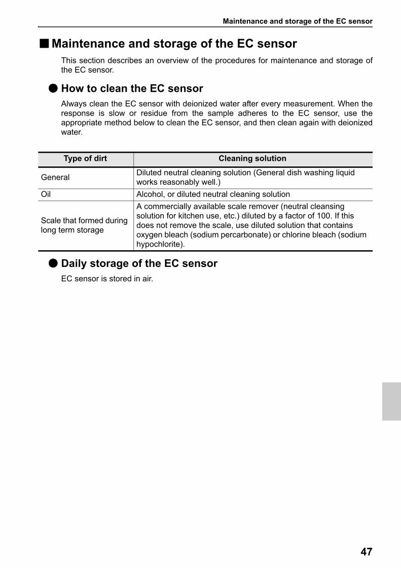
■Maintenance and storage of the EC sensorThis section describes an overview of the procedures for maintenance and storage ofthe EC sensor.
● How to clean the EC sensorAlways clean the EC sensor with deionized water after every measurement. When theresponse is slow or residue from the sample adheres to the EC sensor, use theappropriate method below to clean the EC sensor, and then clean again with deionizedwater.
● Daily storage of the EC sensorEC sensor is stored in air.
Type of dirt Cleaning solution
GeneralDiluted neutral cleaning solution (General dish washing liquid works reasonably well.)
Oil Alcohol, or diluted neutral cleaning solution
Scale that formed during long term storage
A commercially available scale remover (neutral cleansing solution for kitchen use, etc.) diluted by a factor of 100. If this does not remove the scale, use diluted solution that contains oxygen bleach (sodium percarbonate) or chlorine bleach (sodium hypochlorite).
Maintenance and storage of the DO sensor
48
■Maintenance and storage of the DO sensorThis section describes an overview of the procedures for maintenance and storage ofthe DO sensor to be performed as part of daily use.
● How to clean the DO sensorWhen the membrane of a sensor become dirty, the response time may slow or an errormay occur in the calibration results. Clean the sensor with deionized water and wipe itwith a soft cloth, take care not to damage it.
● Daily storage of the DO sensorIf the membrane of a sensor becomes dry, the response will be slow. Store in a moistatmosphere. Follow the steps below to properly store the sensor:
1. Wash the sensor well with pure water (or deionized water) to remove sample
2. Wash the inside of the calibration bottle with pure water (or deionized water), thenadd enough pure water (or deionized water) to soak the sponge.
3. Thread the calibration bottle onto the probe.
Note
When the sensor will not be used for a long period, store it in a cool and dark location byfollowing the sensor storage procedure detailed above.
Maintenance and storage of the ION sensor
49
■Maintenance and storage of the ION sensorThis section describes an overview of the procedures for maintenance and storage ofthe ION sensor to be performed as part of daily use.
● How to clean the ION sensorWhen the membrane of a sensor become dirty, the response time may slow or an errormay occur in the calibration results. Clean a sensor with deionized water and wipe itwith a soft cloth, take care not to damage it.
● Daily storage of the ION sensorFollow the steps below to properly store the sensor correctly.
1. Wash the sensor well with pure water (or deionized water) to remove sample
2. Store in accordance with the instruction manual for each Ion selective electrode.
Note
When the sensor will not be used for a long period, store it by following the sensor storageprocedure detailed above.
Error message
50
Error messages and trouble shooting
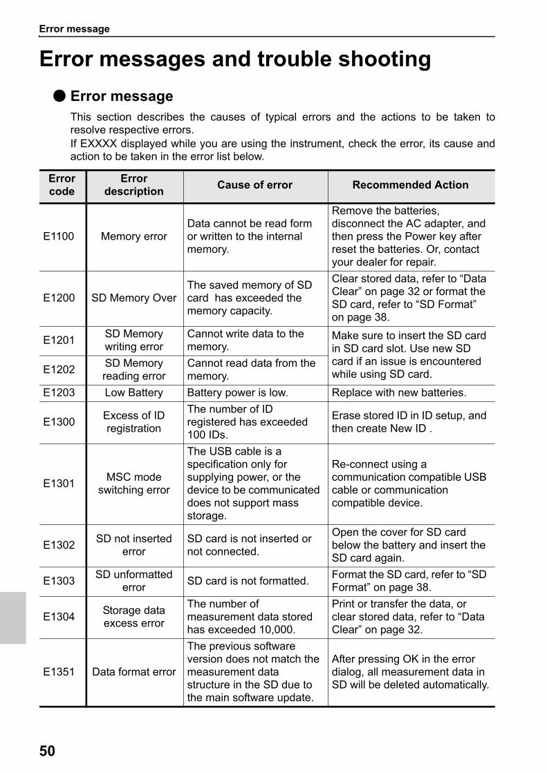
● Error messageThis section describes the causes of typical errors and the actions to be taken toresolve respective errors.If EXXXX displayed while you are using the instrument, check the error, its cause andaction to be taken in the error list below.
Error code
Error description
Cause of error Recommended Action
E1100 Memory errorData cannot be read form or written to the internal memory.
Remove the batteries, disconnect the AC adapter, and then press the Power key after reset the batteries. Or, contact your dealer for repair.
E1200 SD Memory OverThe saved memory of SD card has exceeded the memory capacity.
Clear stored data, refer to “Data Clear” on page 32 or format the SD card, refer to “SD Format” on page 38.
E1201SD Memory writing error
Cannot write data to the memory.
Make sure to insert the SD card in SD card slot. Use new SD card if an issue is encountered while using SD card.E1202
SD Memory reading error
Cannot read data from the memory.
E1203 Low Battery Battery power is low. Replace with new batteries.
E1300Excess of ID registration
The number of ID registered has exceeded 100 IDs.
Erase stored ID in ID setup, and then create New ID .
E1301MSC mode
switching error
The USB cable is a specification only for supplying power, or the device to be communicated does not support mass storage.
Re-connect using a communication compatible USB cable or communication compatible device.
E1302SD not inserted
errorSD card is not inserted or not connected.
Open the cover for SD card below the battery and insert the SD card again.
E1303SD unformatted
errorSD card is not formatted.
Format the SD card, refer to “SD Format” on page 38.
E1304Storage data excess error
The number of measurement data stored has exceeded 10,000.
Print or transfer the data, or clear stored data, refer to “Data Clear” on page 32.
E1351 Data format error
The previous software version does not match the measurement data structure in the SD due to the main software update.
After pressing OK in the error dialog, all measurement data in SD will be deleted automatically.
Error message
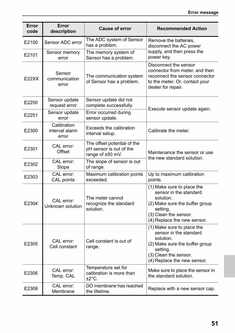
51
E2100 Sensor ADC errorThe ADC system of Sensor has a problem.
Remove the batteries, disconnect the AC power supply, and then press the power key.E2101
Sensor memory error
The memory system of Sensor has a problem.
E22XXSensor
communication error
The communication system of Sensor has a problem.
Disconnect the sensor connector from meter, and then reconnect the sensor connector to the meter. Or, contact your dealer for repair.
E2250Sensor update request error
Sensor update did not complete successfully.
Execute sensor update again.E2251
Sensor update error
Error occurred during sensor update.
E2300Calibration
interval alarm error
Exceeds the calibration interval setup.
Calibrate the meter.
E2301CAL error:
Offset
The offset potential of the pH sensor is out of the range of ±50 mV. Maintenance the sensor or use
the new standard solution.E2302
CAL error: Slope
The slope of sensor is out of range.
E2303CAL error: CAL points
Maximum calibration points exceeded.
Up to maximum calibration points.
E2304CAL error:
Unknown solution
The meter cannot recognize the standard solution.
(1) Make sure to place the sensor in the standard solution.
(2) Make sure the buffer group setting.
(3) Clean the sensor.(4) Replace the new sensor.
E2305CAL error:
Cell constantCell constant is out of range.
(1) Make sure to place the sensor in the standard solution.
(2) Make sure the buffer group setting.
(3) Clean the sensor.(4) Replace the new sensor.
E2306CAL error: Temp. CAL
Temperature set for calibration is more than ±2°C.
Make sure to place the sensor in the standard solution.
E2308CAL error: Membrane
DO membrane has reached the lifetime.
Replace with a new sensor cap.
Error code
Error description
Cause of error Recommended Action
Specification
52
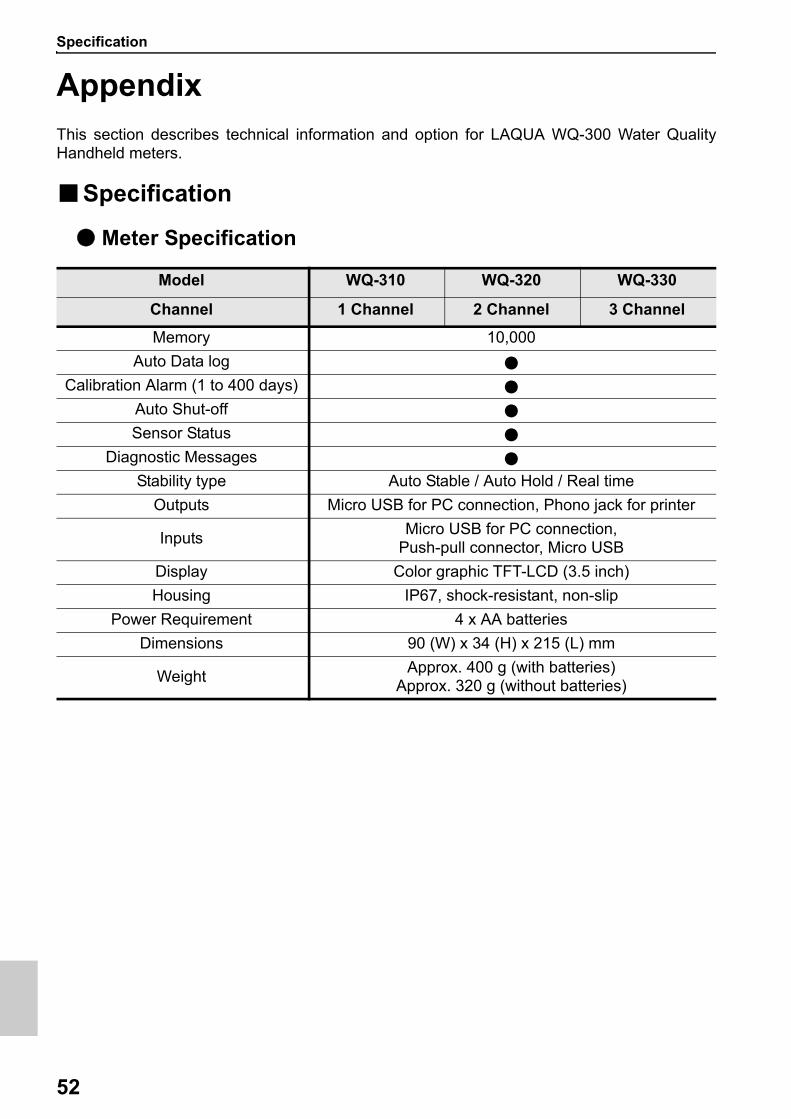
AppendixThis section describes technical information and option for LAQUA WQ-300 Water QualityHandheld meters.
■Specification
● Meter Specification
Model WQ-310 WQ-320 WQ-330
Channel 1 Channel 2 Channel 3 Channel
Memory 10,000
Auto Data log ●
Calibration Alarm (1 to 400 days) ●
Auto Shut-off ●
Sensor Status ●
Diagnostic Messages ●
Stability type Auto Stable / Auto Hold / Real time
Outputs Micro USB for PC connection, Phono jack for printer
InputsMicro USB for PC connection,
Push-pull connector, Micro USB
Display Color graphic TFT-LCD (3.5 inch)
Housing IP67, shock-resistant, non-slip
Power Requirement 4 x AA batteries
Dimensions 90 (W) x 34 (H) x 215 (L) mm
WeightApprox. 400 g (with batteries)
Approx. 320 g (without batteries)

Specification
53
● pH Sensor Head specification
pH Sensor Head Model300PH-2 (2m cable) / 300PH-5 (5m cable)
pH/mV/Temp (°C/°F)
pH
Range -2.00 to 20.00 pH-2.000 to 20.000 pH
Resolution -2.00 to +20.00: 0.01 pH-2.000 to +20.000:0.001 pH
Accuracy -2.00 to +20.00:±0.01 pH-2.000 to +20.000:±0.005 pH
Calibration Points Up to 5
pH Buffer Groups USA, DIN, NIST, NIST (10), Custom
mV
Range ±1000.0 mV
Resolution 0.1 mV
Accuracy ±0.1 mV
Temperature
Temperature Range
ºC: -30.0 to +130.0ºF: -22.0 to +266.0
*Operating Temperature range of pH sensor head: 0 to 60ºC
Resolution 0.1°C/°F
Accuracy ºC: ±0.5ºF: ±0.9
Calibration points 1
Specification
54
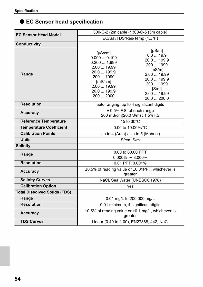
● EC Sensor head specification
EC Sensor Head Model300-C-2 (2m cable) / 300-C-5 (5m cable)
EC/Sal/TDS/Res/Temp (°C/°F)
Conductivity
Range
[μS/cm]0.000 ... 0.1990.200 ... 1.9992.00 ... 19.9920.0 ... 199.9200 ... 1999
[mS/cm]2.00 ... 19.9920.0 ... 199.9200 ... 2000
[µS/m]0.0 ... 19.9
20.0 ... 199.9200 ... 1999
[mS/m]2.00 ... 19.9920.0 ... 199.9200 ... 1999
[S/m]2.00 ... 19.9920.0 ... 200.0
Resolution auto ranging, up to 4 significant digits
Accuracy ± 0.5% F.S. of each range200 mS/cm(20.0 S/m) : 1.5%F.S
Reference Temperature 15 to 30°C
Temperature Coefficient 0.00 to 10.00%/°C
Calibration Points Up to 4 (Auto) / Up to 5 (Manual)
Units S/cm, S/m
Salinity
Range 0.00 to 80.00 PPT0.000% ~ 8.000%
Resolution 0.01 PPT, 0.001%
Accuracy ±0.5% of reading value or ±0.01PPT, whichever is greater
Salinity Curves NaCl, Sea Water (UNESCO1978)
Calibration Option Yes
Total Dissolved Solids (TDS)
Range 0.01 mg/L to 200,000 mg/L
Resolution 0.01 minimum, 4 significant digits
Accuracy ±0.5% of reading value or ±0.1 mg/L, whichever is greater
TDS Curves Linear (0.40 to 1.00), EN27888, 442, NaCl
Specification
55
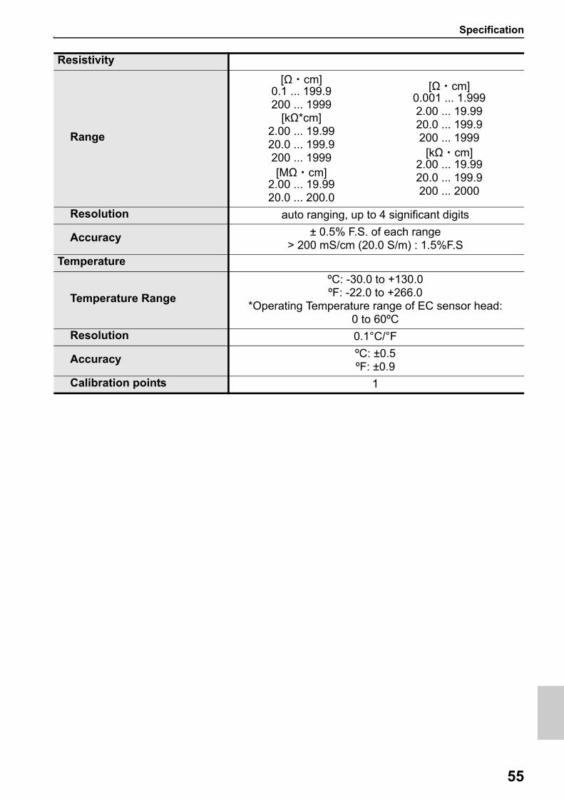
Resistivity
Range
[Ω ・ cm]0.1 ... 199.9200 ... 1999
[kΩ*cm]2.00 ... 19.9920.0 ... 199.9200 ... 1999[MΩ ・ cm]
2.00 ... 19.9920.0 ... 200.0
[Ω ・ cm]0.001 ... 1.9992.00 ... 19.9920.0 ... 199.9200 ... 1999
[kΩ ・ cm]2.00 ... 19.9920.0 ... 199.9200 ... 2000
Resolution auto ranging, up to 4 significant digits
Accuracy ± 0.5% F.S. of each range> 200 mS/cm (20.0 S/m) : 1.5%F.S
Temperature
Temperature Range
ºC: -30.0 to +130.0ºF: -22.0 to +266.0
*Operating Temperature range of EC sensor head: 0 to 60ºC
Resolution 0.1°C/°F
Accuracy ºC: ±0.5ºF: ±0.9
Calibration points 1
Specification
56
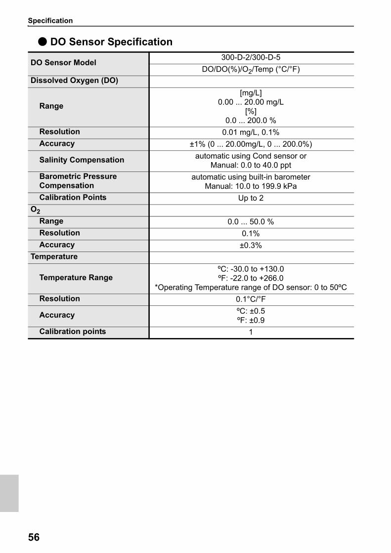
● DO Sensor Specification
DO Sensor Model300-D-2/300-D-5
DO/DO(%)/O2/Temp (°C/°F)
Dissolved Oxygen (DO)
Range
[mg/L]0.00 ... 20.00 mg/L
[%]0.0 ... 200.0 %
Resolution 0.01 mg/L, 0.1%
Accuracy ±1% (0 ... 20.00mg/L, 0 ... 200.0%)
Salinity Compensation automatic using Cond sensor or Manual: 0.0 to 40.0 ppt
Barometric Pressure Compensation
automatic using built-in barometer Manual: 10.0 to 199.9 kPa
Calibration Points Up to 2
O2
Range 0.0 ... 50.0 %
Resolution 0.1%
Accuracy ±0.3%
Temperature
Temperature RangeºC: -30.0 to +130.0ºF: -22.0 to +266.0
*Operating Temperature range of DO sensor: 0 to 50ºC
Resolution 0.1°C/°F
Accuracy ºC: ±0.5ºF: ±0.9
Calibration points 1
Specification
57
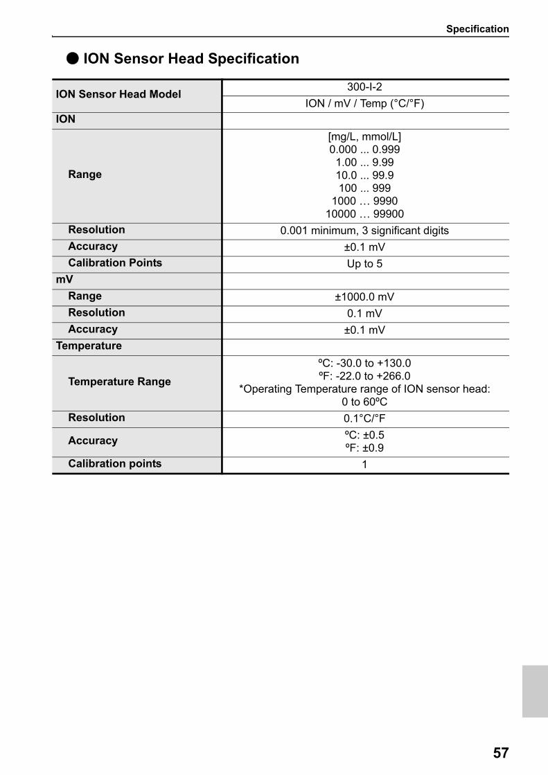
● ION Sensor Head Specification
ION Sensor Head Model300-I-2
ION / mV / Temp (°C/°F)
ION
Range
[mg/L, mmol/L]0.000 ... 0.9991.00 ... 9.9910.0 ... 99.9100 ... 999
1000 … 999010000 … 99900
Resolution 0.001 minimum, 3 significant digits
Accuracy ±0.1 mV
Calibration Points Up to 5
mV
Range ±1000.0 mV
Resolution 0.1 mV
Accuracy ±0.1 mV
Temperature
Temperature Range
ºC: -30.0 to +130.0ºF: -22.0 to +266.0
*Operating Temperature range of ION sensor head: 0 to 60ºC
Resolution 0.1°C/°F
Accuracy ºC: ±0.5ºF: ±0.9
Calibration points 1
Specification
58
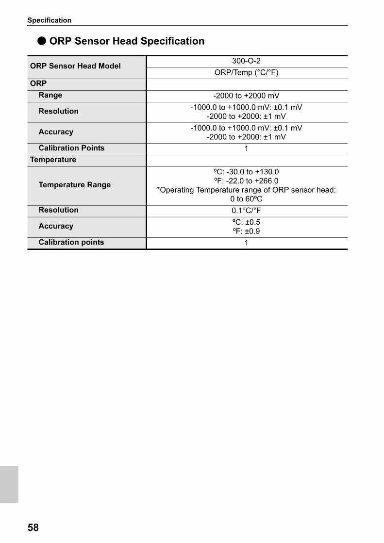
● ORP Sensor Head Specification
ORP Sensor Head Model300-O-2
ORP/Temp (°C/°F)
ORP
Range -2000 to +2000 mV
Resolution -1000.0 to +1000.0 mV: ±0.1 mV-2000 to +2000: ±1 mV
Accuracy -1000.0 to +1000.0 mV: ±0.1 mV-2000 to +2000: ±1 mV
Calibration Points 1
Temperature
Temperature Range
ºC: -30.0 to +130.0ºF: -22.0 to +266.0
*Operating Temperature range of ORP sensor head: 0 to 60ºC
Resolution 0.1°C/°F
Accuracy ºC: ±0.5ºF: ±0.9
Calibration points 1

http://www.horiba-adt.jp
For any questions regarding this product, please contact your local agency, or inquire from thefollowing website.http://global.horiba.com/contact_e/index.htm
31, Miyanonishi-cho, Kisshoin Minami-ku, Kyoto 601-8306, Japan