predictive friction simulation of 3-cylinder and 4 ... · higher engine speeds 07-10-2019...
TRANSCRIPT

Predictive Friction simulation of 3-cylinder and
4-cylinder IC engines
Anoop Suryanarayana, Engine CAE, Volvo Cars, Security Class: Proprietary

AGENDAIntroduction1.
• Objective
• Motivation to predict friction
3-Cylinder Engines2.• Simulations performed by Gamma Technologies
• Validation with measurements
• Key observations and conclusions
4-Cylinder Engines3.• Simulation performed by Volvo Cars
• Validation with measurements
• Key observations and conclusions
Conclusions and further developments4.
07-10-2019 Predictive Friction simulation of 3-cylinder and 4-cylinder IC engines, Anoop Suryanarayana, Volvo Car Group 2
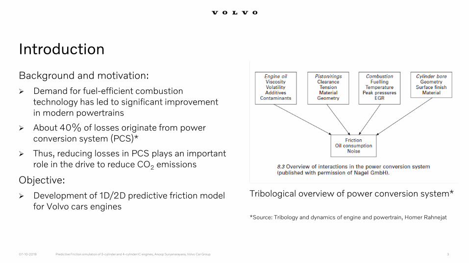
Introduction
Background and motivation:
Demand for fuel-efficient combustion technology has led to significant improvement in modern powertrains
About 40% of losses originate from power conversion system (PCS)*
Thus, reducing losses in PCS plays an important role in the drive to reduce CO2 emissions
Objective:
Development of 1D/2D predictive friction model for Volvo cars engines
07-10-2019 Predictive Friction simulation of 3-cylinder and 4-cylinder IC engines, Anoop Suryanarayana, Volvo Car Group 3
Tribological overview of power conversion system*
*Source: Tribology and dynamics of engine and powertrain, Homer Rahnejat

3-Cylinder Engine
Acknowledgements
Pete Nguyen and Gamma Technologies team
07-10-2019 Predictive Friction simulation of 3-cylinder and 4-cylinder IC engines, Anoop Suryanarayana, Volvo Car Group 4

3-Cylinder Engine
Acknowledgements
Pete Nguyen and Gamma Technologies team
07-10-2019 Predictive Friction simulation of 3-cylinder and 4-cylinder IC engines, Anoop Suryanarayana, Volvo Car Group 5
Rigid Crankshaft model
Will be discussed here

Rigid Crankshaft model
GEM3D used to generate GT-SUITE crank model from CAD step file
• Conrod master weight added to crankpin
Model includes
• 2D Main Bearings
• Front and rear oil seals
• Thrust Bearings
Features
• Rigid crankshaft model
• Oil shear thinning model based on measured oil properties
• Bearing clearance, oil supply pressure, seal friction torque are matched to measured data
• Surface roughness values are assumed
07-10-2019 Predictive Friction simulation of 3-cylinder and 4-cylinder IC engines, Anoop Suryanarayana, Volvo Car Group 6
GT-ISE v2017
3-Cylinder Engine

Comparison with measurements
• Friction is under predicted as speed increases
Crankshaft model Validation with measurements
07-10-2019 Predictive Friction simulation of 3-cylinder and 4-cylinder IC engines, Anoop Suryanarayana, Volvo Car Group 7
FM
EP
[B
ar]
Measured trend is less linear!
3-Cylinder Engine

Various investigations were performed to explain the difference between
measured and simulated results
• Tuning of bearing heat loss fraction
• Tuning of bearing surface roughness
Both have a very small tuning effect and does not improve the results with respect to
measurement
Crankshaft model – Effects of tuning parameters
07-10-2019 Predictive Friction simulation of 3-cylinder and 4-cylinder IC engines, Anoop Suryanarayana, Volvo Car Group 8
3-Cylinder Engine

Unique behavior of 3-Cylinder Crankshafts
Measured data from previous GT projects show similar non-linear trend
Also, from the scatter band it is clear that this trend is seen in other 3-cylinder crankshafts
07-10-2019 Predictive Friction simulation of 3-cylinder and 4-cylinder IC engines, Anoop Suryanarayana, Volvo Car Group 9
3-Cylinder Engine
FM
EP
[B
ar]
Engine Speed [RPM]
Component friction results - CRANKSHAFT

Hypothesis: Possible effect of bending
The inline 3 has a unique topology
When no conrod/piston is assembled, the free crankshaft has a rigid whirl mode that causes edge loads in the bearings
Thus, asperity contact at the edges causes high friction which is seen at higher engine speeds
07-10-2019 Predictive Friction simulation of 3-cylinder and 4-cylinder IC engines, Anoop Suryanarayana, Volvo Car Group 10
3-Cylinder Engine
Image for representation of our hypothesis*
*Source: Rotor Systems: Analysis and Identification, Rajiv Tiwari

Proposed study
Model Fidelity changes:
3D-Beam Dynamic Crankshaft
• Purely for tilt effect
• Local bending curvature is minimal
Bearings are Reynolds Eq. JournalBearingHD3D (asymmetric pressure)
07-10-2019 Predictive Friction simulation of 3-cylinder and 4-cylinder IC engines, Anoop Suryanarayana, Volvo Car Group 11
3-Cylinder Engine
JournalBearingHD3D
In-Plane Loading Out-Of-Plane Loading Torsional Loading
Web Stiffness
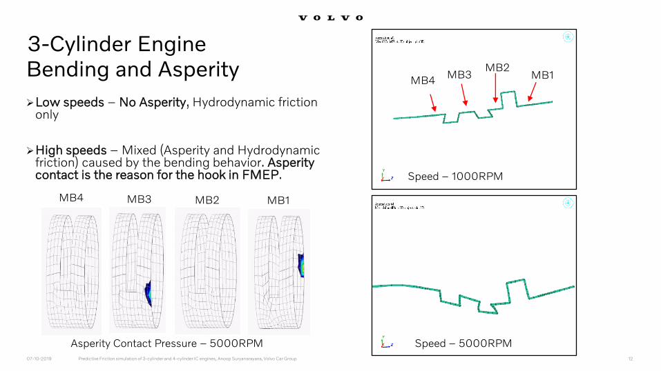
Bending and Asperity
Low speeds – No Asperity, Hydrodynamic friction only
High speeds – Mixed (Asperity and Hydrodynamic friction) caused by the bending behavior. Asperity contact is the reason for the hook in FMEP.
07-10-2019 Predictive Friction simulation of 3-cylinder and 4-cylinder IC engines, Anoop Suryanarayana, Volvo Car Group 12
Asperity Contact Pressure – 5000RPM
MB4 MB3 MB2 MB1
Speed – 5000RPM
MB4MB3
MB2MB1
3-Cylinder Engine
Speed – 1000RPM

Oil Film Pressure
07-10-2019 Predictive Friction simulation of 3-cylinder and 4-cylinder IC engines, Anoop Suryanarayana, Volvo Car Group 13
Speed – 1000RPM
MB4 MB3MB2
MB1 MB4
MB3 MB2
MB1
Speed – 5000RPM
3-Cylinder Engine

Conclusion: Crankshaft only
Predicted FMEP for different models –Crankshaft only:
Measurement (Green line)
Rigid crankshaft with 2D mobility main bearings (Red solid line)
Bending crankshaft with 3D FE hydrodynamic main bearings (Blue solid line)
Thus, edge loading at high speed due to bending explains the non-linear increase in friction in the crankshaft.
07-10-2019 Predictive Friction simulation of 3-cylinder and 4-cylinder IC engines, Anoop Suryanarayana, Volvo Car Group 14
FM
EP
[B
ar]
3-Cylinder Engine
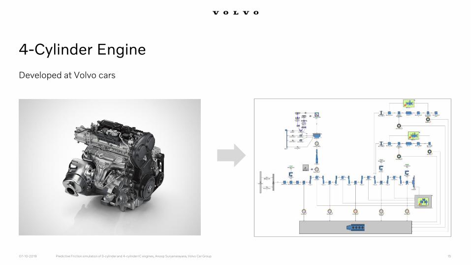
4-Cylinder Engine
Developed at Volvo cars
07-10-2019 Predictive Friction simulation of 3-cylinder and 4-cylinder IC engines, Anoop Suryanarayana, Volvo Car Group 15

Step - 1
• Friction analysis Crankshaft
• Includes Crankshaft with Main bearings, Master weights and Radial sealing rings
• FMEP is calculated using the friction torque
Step - 2
• Friction analysis Cranktrain
• Includes Crankshaft with Main bearings, Radial Sealing rings, Pistons, Rings, Pins, Connecting rods
• Open Cylinder, no gas forces on Piston
• FMEP is calculated using the friction torque
Step - 3
• Friction calculation of Piston group and connecting rod
• “FMEP of Step-2” minus “FMEP of Step-1”
• This gives us the friction in Piston group and connecting rod
Steps of friction strip Measurement
07-10-2019 Predictive Friction simulation of 3-cylinder and 4-cylinder IC engines, Anoop Suryanarayana, Volvo Car Group 16
4-Cylinder Engine

Step-1: Rigid Crankshaft model
GEM-3D used to generate GT-SUITE crank model from CAD step file
• Conrod master weight added to crankpin
Model Includes• Main Bearings
• Front and rear oil seals
• Thrust Bearings
Features• Rigid crankshaft model
• Oil shear thinning model based on measured oil properties
• Oil supply pressure, seal friction torque are matched to measured data
• Bearing clearance, surface roughness values are assumed
07-10-2019 Predictive Friction simulation of 3-cylinder and 4-cylinder IC engines, Anoop Suryanarayana, Volvo Car Group 17
GT-ISE v2019
4-Cylinder Engine

Validation with measurements
At 3000rpm, the step in the measurement is due to change in oil pressure.
Good match was seen against friction strip test results.
07-10-2019 Predictive Friction simulation of 3-cylinder and 4-cylinder IC engines, Anoop Suryanarayana, Volvo Car Group 18
4-Cylinder Engine
FM
EP
[B
ar]

Step 2: Cranktrain with Piston group model
Model consists of• Piston
• Small end and big end bearings
• Conrod
• Mass balance system with roller bearings
Model features• Ring data
• Piston skirt data
• RollerBearing 2D template
Assumptions• Approximated clearances in cylinder bore and conrod
bearings
• Surface roughness
• Bore distortions are not considered
07-10-2019 Predictive Friction simulation of 3-cylinder and 4-cylinder IC engines, Anoop Suryanarayana, Volvo Car Group 19
4-Cylinder Engine

Cranktrain Model Validation with measurements
At 3000rpm, the step in the measurement is due to change in oil pressure.
Good correlation with the friction strip test results.
07-10-2019 Predictive Friction simulation of 3-cylinder and 4-cylinder IC engines, Anoop Suryanarayana, Volvo Car Group 20
4-Cylinder Engine
FM
EP
[B
ar]
FM
EP
[B
ar]

Step - 1
• Friction analysis Crankshaft
• Includes Crankshaft with Main bearings, Master weights and Radial sealing rings
• FMEP is calculated using the friction torque
Step - 2
• Friction analysis Cranktrain
• Includes Crankshaft with Main bearings, Radial Sealing rings, Pistons, Rings, Pins, Connecting rods
• Open Cylinder, no gas forces on Piston
• FMEP is calculated using the friction torque
Step - 3
• Friction calculation of Piston group and connecting rod
• “FMEP of Step-2” minus “FMEP of Step-1”
• This gives us the friction in Piston group and connecting rod
Steps of friction strip Measurement
07-10-2019 Predictive Friction simulation of 3-cylinder and 4-cylinder IC engines, Anoop Suryanarayana, Volvo Car Group 21
4-Cylinder Engine
No need as GT-SUITE
provides us these results

Components frictions: Simulated vs Measurement results
07-10-2019 Predictive Friction simulation of 3-cylinder and 4-cylinder IC engines, Anoop Suryanarayana, Volvo Car Group 22
4-Cylinder Engine
Temperature 90C

13-09-2019 VEP4 Gen3 HP Friction Simulation, Anoop Suryanarayana, Engine CAE Solids 23
4-Cylinder EngineCrankshaft friction: simulated vs measurement resultsTemperature 90C

Understanding the difference: Simulation vs Measurements
13-09-2019 VEP4 Gen3 HP Friction Simulation, Anoop Suryanarayana, Engine CAE Solids 24
4-Cylinder Engine
Difference in simulation and measurement:
In the friction strip test, only rotating masses ofthe connecting rod is added as master weights.This reduces the bearing load.
Approx. 2.5 times increase in bearing load isobserved at 6000rpm with piston groupincluded due to piston reciprocating forces.
Thus, effects from the oscillating mass forcesare not seen in the measurement of crankshaftfriction.
0
0,2
0,4
0,6
0,8
1
1,2
0 2000 4000 6000 8000
NO
RM
AL
ISE
D F
OR
CE
[N
]ENGINE SPEED [RPM]
Maximum Bearing Load on MB 3
Maximum Bearing Load 3_Master weights
Maximum Bearing Load 3_Piston Group

Piston group friction: simulated vs measurement results
13-09-2019 VEP4 Gen3 HP Friction Simulation, Anoop Suryanarayana, Engine CAE Solids 25
4-Cylinder Engine
Large difference between
simulation and measurement
There is a possibility that in reality
the friction in piston group is less
and our approach in measurement
is incorrect.
So simulation model is helpful to
find these details that we might
have missed in measurement.

GT-SUITE simulation model is a useful tool to understand friction behavior of individual
components, where measurements have limitations.
2D journal bearing model with mobility assumptions are sufficient to obtain faster results.
High fidelity model captures more details with higher accuracies but at the cost of
computational time.
The FMEP values obtained from these models are useful for 1D gas exchange simulation team
as they currently use approximated values.
Final Conclusion
07-10-2019 Predictive Friction simulation of 3-cylinder and 4-cylinder IC engines, Anoop Suryanarayana, Volvo Car Group 26
Discussions with friction strip test supplier to improve the test methodology for piston group.
4-Cylinder engines
• Improve the model further to include camshafts and valve train.
• Methodology to predict friction in piston group assembly.
• Simulation of part load and full load cases to understand friction of the engine.
Future scope
07-10-2019 Predictive Friction simulation of 3-cylinder and 4-cylinder IC engines, Anoop Suryanarayana, Volvo Car Group 27

Thank You