prediction of stress distribution of pressure vessel shell ... vessel. 1. introduction pressure...
TRANSCRIPT

9year XXV, no. 2/2016
KeywordsNumerical simulation, catia software packege, stainless steel,
pressure vessel.
1. IntroductionPressure vessels under internal pressure are widely used as
critical components of different industrial plants, for example for oil and gas transmission [1], as well as electricity production in nuclear and thermal power plants. Specific long-term exploitation of such structures and its role like vital process equipment require accomplishment appropriate technical regulations, during the design and operation.
Today it can be find lots of numerical and experimental papers about cylindrical shells under pressure, while analysis based on finite element methods (FEM) have a main role. Visualization of stress distribution facilitates the detection zone with highest stresses and finding eventually mistakes, thereby saving designing time, hence its application is almost unavoidable in contemporary researches [1-6].
The aim of this study is to perform a comparative analysis of stress distribution in the pressure vessel shell, using a numerical simulation and analytical calculation for operating conditions. Modeling cylindrical pressure vessel was performed in software package CATIA for a real geometry, taking into account a form of vessel head, geometry of connections, supports and welded joints, since they are critical zones for the occurrence of stress concentration. This approach provides the simulation of working and testing conditions and prediction of stress distribution in every part of the vessel shell.
2. Shell-strength calculationStrength calculation of pressure vessel shell is performed
analytically and numerically. Horizontal, cylindrical steel pressure vessel with volume 9 m3 is considered. Testing pressure of the vessel is 11bar. The head wall has a tori spherical shape and no additional reinforcements of the head wall are necessary.
Working (operating) pressure is 8 bar and temperature is 50 ºC and wall thickness is 10 mm. Pressure vessel is made of stainless steel 304L (AISI, Tensile strength, Yield = 210 MPa), and it designed for substances storage that have corrosion effects. Strength calculation of parts of the pressure vessel has been done in accordance with national standards (SRPS ME2.252).
For the cylindrical sheet and cylindrical part of the head, next expression was used:
For spherical part of the head next expression was used:
For torus part of the head next expression was used:
Where are:K(N/mm2) - stress in the wall,S(-) - safe coefficient,v(-) - weld quality coefficient,p(bar) - pressure,s(mm) - wall thickness, β(-) - calculation coefficient,Ds (mm) - outside diameter,Dss (mm) - outside sphere diameter of the head.
3. Numerical simulations Beside of standard analytical calculation, numerical
simulation of stress distribution on the same model and same working parameters is also presented. Finite element method (FEM) was chosen to simulate operating conditions (boundary conditions and load). The CATIA (Computer Aided Three-dimensional Interactive Application) software package has been used for generating finite element meshes, composed of tetrahedron type, three-dimensional finite elements. FEM is based on a physical discretization of the considered parts of a continuum of finite dimensions and simple shapes called finite elements (FE). All finite elements are connected by common nodes to form the original structure. The basic types of finite elements are: one-dimensional (rods, beams, pipe fittings), two-dimensional (triangular, rectangular, membranes, plates and shells), three-dimensional (tetrahedron, prism, axisymmetric and others). In FEM studied domain (the strain body) is shared by using fictitious line on a number of finite elements. Set of finite elements for the entire domain make a network of finite elements. Stress and strains are described by interpolation functions and a finite number of parameters in the nodes. They are the basic parameters of the FEM. When the basic relations in the FEM are setting up, using the same principles and procedures, that are valid beyond the classical discrete models, they relate force and stress and stress and strain. By grouping the basic equations finite elements gets the equation structure in matrix form [5].
Prediction of stress distribution of pressure vessel shell using numerical simulation
M. Prvulovic a, M. Ristic b, S. Budimir c, M. Prokolab d, Z. Milutinovic e
Institut Gosa, Beograd, Serbia
E-mail: a [email protected], b [email protected], c [email protected], d [email protected], e [email protected]

10 year XXV, no. 2/2016
Numerical simulation has been done for both operating and testing pressure. Stress analysis tank is made with FEM. It is an efficient and reliable numerical procedure for modelling both, linear and nonlinear behavior of materials and structures. Numerical method FEM has been used in order to confirm the ability of testing tank pressure to predict the crack of spacemen. Elastoplastic, numerical analysis of the tank made of stainless steel is made. The primary aim was to obtain the maximum strain that correspond to the calculation.
Finite element mesh is consisted of 115,929 elements and 37,515 nodes with three degrees of freedom, so the system has a total of 585,823 equations. A global stiffness matrix system of finite element meshes in this case has 37,515 x 37,515 elements. Using equations which link displacement and strain, and the equations of deformation and stress, stress distribution is determined. External load were entered into the model on the front
surface of the board, while the other plate wedged. In Figure 1 is shown the model of thank with the finite element mesh.
4. Results and discussionIn Table 1, analytical strength calculation results, for both
working and testing conditions, are presented. Second row of results correspond to testing pressure, while third row presents stress values in wall of vessel at operating pressure.
Standard stress calculation results shows that maximum stress value is occur in torus part of head.
Table1. Results of standard strength calculation [MPa].
Sheet Cylindrical part of head
Spherical part of head
Torus part of head
121* 121* 120* 173119.3 119 119.7 171.5
(*) Stress value for cold water testing conditions (p=11 bar)
4.1. Numerical simulation of testing conditions
As discussed in the introduction, the pressure vessel is to be used with the decreased operational pressure, 8 bar but tested pressure is 11bar according relevant standard. The task is to calculate new allowable loads on the weasel walls. The numerical analysis was global, i.e. the pressure vessel was analyzed as a complete structure.
Firstly is done numerical simulation of testing pressure which is P=11 bar and results are shown (Figure 2 and Figure 3).
Figure2 . Pressure test simulation with the testing pressure 11 bar, specimen with the Von Mises stresses.
Figure 3. Section of pressure vessel with the field of stress, calculation preformed with testing pressure 11 bar.
Figure 4. Deformed model of pressure tank calculation preformed with testing pressure 11 bar.
Results of testing conditions simulation shows that the highest stress values in the pressure vessel shell achieved in torus parts of head. Stress values is increased and the environment of supports and connections, the maximum stress in the torus
Figure1. Model specimen with finite element mesh.
11year XXV, no. 2/2016
parts of head, is 1.92•108 N/m2 (Figure 2). Numerical results demonstrate a good agreement with control calculation which value is 1.73•108 N/m2. The vessel is cut in the half to see inner part stress distribution and it can be seen that highest value of stress is in the bottom of thank in area where toroidal part going to spherical, and it is presented in Figure 3.
Deformation of pressure vessel during testing pressure procedure is shown on the Figure 4. Deformation of vessel is exaggerated in software because idea was to see which area has largest displacement and deformation, and it shows that bottom of the vessel has it.
4.2. Numerical simulation of operating conditions
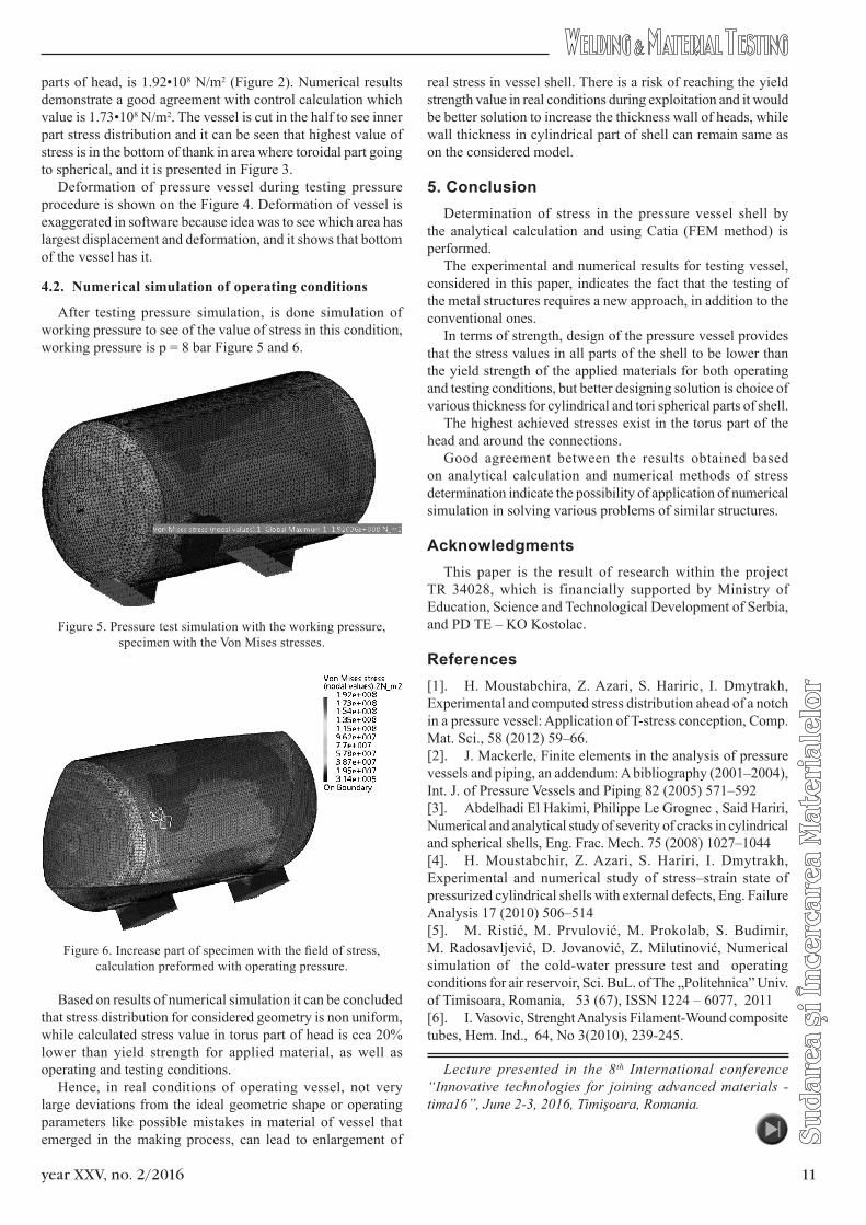
After testing pressure simulation, is done simulation of working pressure to see of the value of stress in this condition, working pressure is p = 8 bar Figure 5 and 6.
Figure 5. Pressure test simulation with the working pressure, specimen with the Von Mises stresses.
Figure 6. Increase part of specimen with the field of stress, calculation preformed with operating pressure.
Based on results of numerical simulation it can be concluded that stress distribution for considered geometry is non uniform, while calculated stress value in torus part of head is cca 20% lower than yield strength for applied material, as well as operating and testing conditions.
Hence, in real conditions of operating vessel, not very large deviations from the ideal geometric shape or operating parameters like possible mistakes in material of vessel that emerged in the making process, can lead to enlargement of
real stress in vessel shell. There is a risk of reaching the yield strength value in real conditions during exploitation and it would be better solution to increase the thickness wall of heads, while wall thickness in cylindrical part of shell can remain same as on the considered model.
5. ConclusionDetermination of stress in the pressure vessel shell by
the analytical calculation and using Catia (FEM method) is performed.
The experimental and numerical results for testing vessel, considered in this paper, indicates the fact that the testing of the metal structures requires a new approach, in addition to the conventional ones.
In terms of strength, design of the pressure vessel provides that the stress values in all parts of the shell to be lower than the yield strength of the applied materials for both operating and testing conditions, but better designing solution is choice of various thickness for cylindrical and tori spherical parts of shell.
The highest achieved stresses exist in the torus part of the head and around the connections.
Good agreement between the results obtained based on analytical calculation and numerical methods of stress determination indicate the possibility of application of numerical simulation in solving various problems of similar structures.
AcknowledgmentsThis paper is the result of research within the project
TR 34028, which is financially supported by Ministry of Education, Science and Technological Development of Serbia, and PD TE – KO Kostolac.
References[1]. H. Moustabchira, Z. Azari, S. Hariric, I. Dmytrakh, Experimental and computed stress distribution ahead of a notch in a pressure vessel: Application of T-stress conception, Comp. Mat. Sci., 58 (2012) 59–66.[2]. J. Mackerle, Finite elements in the analysis of pressure vessels and piping, an addendum: A bibliography (2001–2004), Int. J. of Pressure Vessels and Piping 82 (2005) 571–592[3]. Abdelhadi El Hakimi, Philippe Le Grognec , Said Hariri, Numerical and analytical study of severity of cracks in cylindrical and spherical shells, Eng. Frac. Mech. 75 (2008) 1027–1044[4]. H. Moustabchir, Z. Azari, S. Hariri, I. Dmytrakh, Experimental and numerical study of stress–strain state of pressurized cylindrical shells with external defects, Eng. Failure Analysis 17 (2010) 506–514[5]. M. Ristić, M. Prvulović, M. Prokolab, S. Budimir, M. Radosavljević, D. Jovanović, Z. Milutinović, Numerical simulation of the cold-water pressure test and operating conditions for air reservoir, Sci. BuL. of The „Politehnica” Univ. of Timisoara, Romania, 53 (67), ISSN 1224 – 6077, 2011 [6]. I. Vasovic, Strenght Analysis Filament-Wound composite tubes, Hem. Ind., 64, No 3(2010), 239-245.
Lecture presented in the 8th International conference “Innovative technologies for joining advanced materials - tima16”, June 2-3, 2016, Timişoara, Romania.