precision controls - sms tork · precision controls kft , veszprém, hungary, ... pressure...
TRANSCRIPT

Connectors
Precision Controls
Nass Controls LP Nass Magnet GmbH Precision Controls Kft.

Page 34
Page 4 - 5
Connectors
Introduction
Page 6 - 7Construction of Connectors without Cable
Page 8 - 9General Data, Materials, Colours
Circuit Versions
01 - 06 Page 28 07 - 12 Page 29 13 - 18 Page 30 19 - 27 Page 31 28 - 29 Page 32
Form A acc to EN 175301-803 (ISO 4400) Technical Data Page 10 Product Code Part Numbers of Standard Versions Page 11
Industrial Type B 11mm Technical Data Page 12 Product Code Part Numbers of Standard Versions Page 13
Form B acc to EN 175301-803 (ISO 6952) Technical Data Page 14 Product Code Part Numbers of Standard Versions Page 15
Micro Type C (9,4 mm) Technical Data Page 16 Product Code Part Numbers of Standard Versions Page 17
Form C acc to EN 175301-803 (ISO 15217) (8mm) Technical Data Page 18 Product Code Part Numbers of Standard Versions Page 19
Connectors with Moulded Cable
Form A acc to EN 175301-803 (ISO 4400) Technical Data Page 22 Product Code Part Numbers of Standard Versions Page 23
Industrial Type B 11mm Technical Data Page 24 Product Code Part Numbers of Standard Versions Page 25
Form B acc to EN 175301-803 (ISO 6952) Technical Data Page 26 Product Code Part Numbers of Standard Versions Page 27
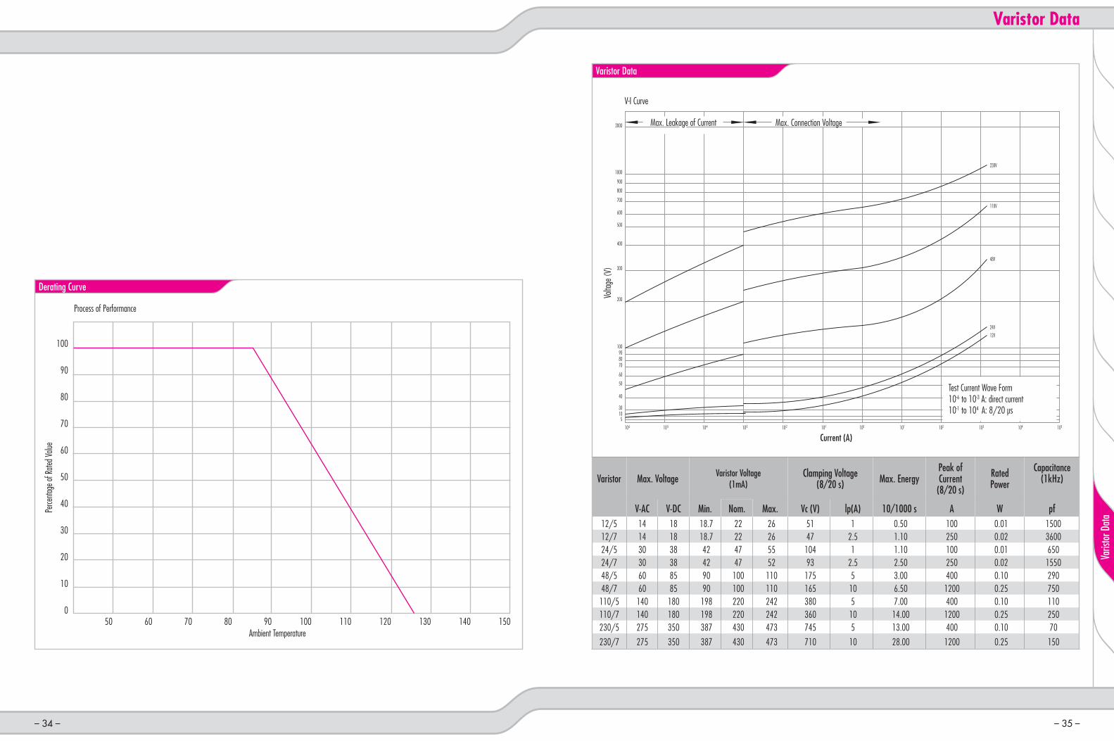
Derating Curve
Page 35Varistor Data
Page 20 - 21General Data, Materials, Colours
Page 33Circuit Version Numbers
– 2 –
Gene
ral
– 3 –
Constru
ction o
f Conne
ctors
Conn
ector
sCir
cuit V
ersio
nsCirc
uit Ver
sion Nu
mbers
Varis
tor D
ata
General

Nass Magnet GmbH, Hanover, Germany, is the headquarters of the company group Over 200 employees work to develop and produce electromagnetic pilot valves suited for air, inert gases, and other media, as well as systems for the automotive industry
Nass Controls LP, New Baltimore, Michigan, USA, is the distribution center for the North/South American and Australian markets Here, the components produced by the company group are assembled and tested to create final products for the customer’s specific application In addition, other products and services combine to create a complete product range to satisfy the widely varied needs of the customers
Precision Controls Kft , Veszprém, Hungary, employs approximately 250 knowledgeable individuals who work to develop and produce solenoid connectors, coils and function fitting products They also produce a portion of the assemblies for the group as a whole
Nass Magnet GmbH:Klaus H Kirchheim President Peter Morgenstern Managing Director Thomas Groetzinger Managing Director
Nass Controls LP: Klaus H Kirchheim President R Randall Bennett Managing Director Peter Morgenstern Managing Director
Precision Controls Kft :Klaus H Kirchheim President Peter Morgenstern Managing Director Dennis Müller Managing Director
The Companies
The Enterprise
A group of successful companies:Our group of companies is one of the largest European manufacturer of electromagnetic pilot valves suited for the following media:
airinert gasesother media
as well as of magnetic systems for automotive applications, function fittings and connectors
All over the world approximately 500 employees are engaged in the development, production and sale of our products About 40 engineers in our development and construction departments will be glad to give you competent advice in questions of engineering-service, product optimization as well as rationalization In case of any question, they will be available to help you with their know-how The 80+ history of our company group represents equally continuity in the economical development and flexible adjustment to time and market The fields of application of our products cover many different industrial branches, e g
industrial pneumaticsfood industrymedical technologycontrol technologyprocess technologygas technologypaper and printing technologypetroleum industryenvironmental technologyrail vehicleshydraulics
A list of our current trading partners can be found on our homepage www precisioncontrols hu
Distribution Network
– 4 –– 4 –
Gene
ral
– 5 –
Constru
ction o
f Conne
ctors
Conn
ector
sCa
ble Co
nnec
tors
Circu
it Ver
sions
Circuit
Version
Numb
ersVa
ristor
Data
General
Gene
ral

1 Terminal block with clamping contact (standard version)
Two-piece housing2b Housing 8 Cover9 Cover gasket
2a One-piece housing
3 Grommet4 Pressure ring5 Pressure screw
6a/b Central-fixing screw
7a Profile gasket
7b Flat gasket
10 Circuit Board
Valve Connectors
Construction of Connectors without Cable
Electrical connectors provide a fast and reliable interface for connection/disconnection to/from hydraulic and pneumatic valves, pressure switches, motor drives and other electrically driven industrial and mobil components The product offering includes Form A, B and C, according to CECC/EN 175301-803 Innovative wire connecting methods and user-friendly assembly allow for easy installation to the electrical device The connectors are available in many circuit versions to meet the customer’s specific application requirements
– 6 –– 6 – – 7 –
Constru
ction o
f Conne
ctors
Construction of Connectors
3
4
5
6a
6b
7b 7a
10
1
2a2b
8
9

FormGeneral Data Form A 1) Industrial
Type B Form B 1) Micro Type C Form C 1)
Operating voltage – versions without circuit UC max 250 V UC max 110 V UC max 250 VOperating voltage – versions with circuit See circuit versions, page 28 - 32Nominal current 2) 10 A 6 AContact resistance ≤4 mOhmCable diameter 5-10 mm 5-6 mmCross section of conductor with sleeve3) 0 5-1 5 mm2; 4) 0 34-0 5mm2
Cross section of conductor without sleeve5) 0 5-1 5 mm2 0 34-0 5mm2
Degree of protection acc to DIN EN 60529 IP65Ambient temperature for versions with …Housings in polyamide, black, grey, natural -25 C°- 125 C°Housings in polyamide, transparent -25 C°- 60 C°Housings with fire protection class V1 acc to UL 94 -25 C°- 125 C°Housings for explosion-proof areas -20 C°- 95 C°Profile gasket or flat gasket in NBR -25 C°- 90 C°Profile gasket or flat gasket in silicone -25 C°- 125 C°Tightening torque for Pressure screw max 1 8 ±0 2 Nm max 1 6 ±0 2 NmCentral-fixing screw max 0,4±0,1 NmContact screw 0 2+0,1 NmDimensions of central-fixing screw for One-piece housing M 3x33 5 M 2 5x27Two-piece housing M 3x37 5 ---
1) Acc to EN 175301-8032) Connectors with circuit in general 1 5 Va, except differently indicated, see page 28-32 Higher current versions upon request 3) We recommend to assemble the flying leads in our connectors with sleeves acc to VDE 0100/520 4) The assembly of the 1 5 mm² flying leads with sleeve is only possible with our standard versions without wire protecting plate 5) We recommend our special version with wire protecting plate for the assembly of the flying leads without sleeve 6) LABS: Substances disturbing the wettability of varnish Explosion-proof areas:- in gas explosive areas of zone 2 They comply with category II3C and the ignition protection type EEx nA II - in areas of zone 22 with flammable dust They comply with category II3D and degree of protection IP 65
MaterialsHousing in polyamide, black, grey, natural; cover black, grey (for two-piece housings); terminal block for form A, Industrial Type B, form B PA6 GF30
Housings in polyamide, transparent; transparent cover (for two-piece housings) PA6-IHousings black; terminal block with fire protection class V1 acc to UL 94 PA6 GF30 V0-equippedHousings transparent, with fire protection class V1 acc to UL 94 Polycarbonate V0-equippedHousings for explosion-proof areas PA6 GF30 dry impact-resistantTerminal block for Micro Type C, form C PA6 6Pressure screw PA6 GF30Contact CuZn, Sn/Cu-platedCentral-fixing screw, contact screw St, 4 8, zinc-platedPressure ring St, zinc-platedGrommet; gasket; cover gasket NBR LABS-free 6) or silicone
ColoursRAL-code of the grey housing and the grey pressure screw RAL 7040 ”window grey”Pressure screw for black and transparent housing blackPressure screw for grey housing greyPressure screw for explosion-proof areas black or blueNBR gasket blackSilicone gasket red
Indications on Usage
General DataMaterialsColours
Hinweise bezüglich der Verwendung
– 8 –– 8 – – 9 –
Conn
ector
s
Connectors

Technical Data
Form A acc. to EN 175301-803 (ISO 4400)Product Code: 6-11, One-piece HousingProduct Code: 6-41, Two-piece Housing
Product code: 6-11 Product code: 6-41One-piece housing Two-piece housing
Standard Product Features: Special Versions as Options:
Clamping contact without wire protecting plate Clamping contact with wire protecting plate
Housing with M 20x1 5 connectionHousing with M 16x1 5 connection
Housing with ½”NPTF connection
Housing and terminal block in polyamide Housing and terminal block in plastic with fire protection class V1 acc to UL94
Colour of housing blackColour of housing greyColour of housing transparent
--------Colour of housing natural (milky)
Standard design of connectors Design of connectors for explosion-proof areasCable gland without cable clamp Cable gland with cable clampGround position 12h Ground position 3h, 6h, 9hCentral-fixing screw in St 4 8 zinc-plated Central-fixing screw in stainless steelPreCon logo in the housing Customized logo on requestPackaging unit 100 pcs Single packaging
Additional special versions are available on request Circuit versions see page 28 - 32
6 - b 1 d e f - 2 h i k
Circuit version number 00: without circuit; 01-99: see page 33; above 99 on request
Circuit version 0= without circuit or components soldered directly to the contact 5= components on the circuit board
Gasket and central-fixing screw 0= without gasket and screw 1= without gasket with standard screw 2= NBR profile gasket, standard screw 3= NBR flat gasket, standard screw 4= silicone flat gasket, standard screw
Ground position and connection 1= 6h, for cable 5-6mm 2= 12h, for cable 5-6mm 3= 6h, for cable 6-8mm 4= 12h, for cable 6-8mm 5= 6h, for cable 8-10mm 6= 12h, for cable 8-10mm Number of poles and colour of housing 1= 2+ground, black 2= 2+ground, grey 3= 2+ground, transparent without circuit or with circuit with components soldered directly to the contact 4= 2+ground, transparent with circuit board 5= 3+ground, black 6= 3+ground, grey 7= 3+ground, transparent without circuit or with circuit with components soldered directly to the contact 8= 3+ground, transparent with circuit board
Housing version 1= One-piece housing 4= Two-piece housing
Part Numbers of Standard Versions
– 10 –– 10 – – 11 –
Conn
ector
s
Connectors
50
28 28
31 35
50
28 28
31 31,5
18

Technical Data
Industrial Type B11mmProduct Code: 6-12, One-piece Housing Product Code: 6-42, Two-piece Housing
Product code: 6-12 Product code: 6-42One-piece housing Two-piece housing
Standard Product Features: Special Versions as Options:
Clamping contact without wire protecting plate Clamping contact with wire protecting plateHousing with M 16x1 5 connection Housing with ½” NPTF connectionHousing and terminal block in polyamide Housing and terminal block in plastic with fire protection class V1 acc to UL94Colour of housing blackColour of housing greyColour of housing transparent
--------Colour of housing natural (milky)
Cable gland without cable clamp Cable gland with cable clampGround position 12h Ground position 6hCentral-fixing screw in St 4 8 zinc-plated Central-fixing screw in stainless steelPreCon logo in the housing Customized logo on requestPackaging unit 100 pcs Single packaging
Additional special versions are available on request Circuit versions see page 28 - 32
6 - b 2 d e f - 2 h i k
Circuit version number 00: without circuit; 01-99: see page 33; above 99 on request
Circuit version 0= without circuit or components soldered directly to the contact 5= components on the circuit board
Gasket and central-fixing screw 0= without gasket and screw 1= without gasket with standard screw 2= NBR profile gasket, standard screw 3= NBR flat gasket, standard screw 4= silicone flat gasket, standard screw
Ground position and connection 1= 6h, for cable 5-6mm 2= 12h, for cable 5-6mm 3= 6h, for cable 6-8mm 4= 12h, for cable 6-8mm 5= 6h, for cable 8-10mm 6= 12h, for cable 8-10mm
Number of poles and colour of housing 1= 2+ground, black 2= 2+ground, grey 3= 2+ground, transparent without circuit or with circuit with components soldered directly to the contact 4= 2+ground, transparent with circuit board
Housing version 1= One-piece housing 4= Two-piece housing
Part Numbers of Standard Versions
– 12 –– 12 – – 13 –
Conn
ector
s
Connectors
48,5
28,5 21
31 35
21
31,5
48,5
28,5
31
11

Technical Data
Form B acc. to EN 175301-803 (ISO 6952)Product Code: 6-13, One-piece Housing Product Code: 6-43, Two-piece Housing
Product code: 6-13 Product code: 6-43One-piece housing Two-piece housing
Standard Product Features: Special Versions as Options:
Clamping contact without wire protecting plate Clamping contact with wire protecting plateHousing with M 16x1 5 connection Housing with ½” NPTF connectionHousing and terminal block in polyamide Housing and terminal block in plastic with fire protection class V1 acc to UL94Colour of housing blackColour of housing greyColour of housing transparent
------Colour of housing natural (milky)
Cable gland without cable clamp Cable gland with cable clampGround position 12h Ground position 6hCentral-fixing screw in St 4 8 zinc-plated Central-fixing screw in stainless steelPreCon logo in the housing Customized logo on requestPackaging unit 100 pcs Single packaging
Additional special versions are available on request Circuit versions see page 28 - 32
6 - b 3 d e f - 2 h i k
Circuit version number 00: without circuit; 01-99: see page 33; above 99 on request
Circuit version 0= without circuit or components soldered directly to the contact 5= components on the circuit board
Gasket and central-fixing screw 0= without gasket and screw 1= without gasket with standard screw 2= NBR profile gasket, standard screw 3= NBR flat gasket, standard screw 4= silicone flat gasket, standard screw
Ground position and connection 1= 6h, for cable 5-6mm 2= 12h, for cable 5-6mm 3= 6h, for cable 6-8mm 4= 12h, for cable 6-8mm 5= 6h, for cable 8-10mm 6= 12h, for cable 8-10mm
Number of poles and colour of housing 1= 2+ground, black 2= 2+ground, grey 3= 2+ground, transparent without circuit or with circuit with components soldered directly to the contact 4= 2+ground, transparent with circuit board
Housing version 1= One-piece housing 4= Two-piece housing
Part Numbers of Standard Versions
– 14 –– 14 – – 15 –
Conn
ector
s
Connectors
48,5
28,5 21
31 35
21
31,5
48,5
28,5
31
10

Technical Data
Micro Type C(9.4 mm)Product Code: 6-14, One-piece Housing
Product code: 6-14One-piece housing
Standard Product Features: Special Versions as Options:
Clamping contact without wire protecting plate ---Housing with M 12 connection ---Colour of housing blackColour of housing greyColour of housing transparent
------Colour of housing natural (milky)
Cable gland without cable clamp ---Ground position 12h Ground position 3h, 6h, 9hCentral-fixing screw in St 4 8 zinc-plated Central-fixing screw in stainless steelPreCon logo in the housing Customized logo on requestPackaging unit 300 pcs Single packaging
Additional special versions are available on request Circuit versions see page 28 - 32
6 - 1 4 d e f - 0 h i k
Circuit version number 00: without circuit; 01-99: see page 33; above 99 on request
Circuit version 0= without circuit or components soldered directly to the contact 5= components on the circuit board
Gasket and central-fixing screw 0= without gasket and screw 1= without gasket with standard screw 2= NBR profile gasket, standard screw 3= NBR flat gasket, standard screw 4= silicone flat gasket, standard screw
Ground position and connection 1= 6h, for cable 5-6mm 2= 12h, for cable 5-6mm
Number of poles and colour of housing 1= 2+ground, black 2= 2+ground, grey 3= 2+ground, transparent without circuit or with circuit with components soldered directly to the contact 4= 2+ground, transparent with circuit board 5= 3+ground, balck 6= 3+ground, grey 7= 3+ground, transparent without circuit or with circuit with components soldered directly to the contact 8= 3+ground, transparent with circuit board
Part Numbers of Standard Versions
– 16 –– 16 – – 17 –
Conn
ector
s
Connectors
15,6 15,9
34,4
26
9,4

Technical Data
Form C acc. to EN 175301-803 (ISO 15217) (8mm)Product Code: 6-15, One-piece Housing
Product code: 6-15One-piece housing
Standard Product Features: Special Versions as Options:
Clamping contact without wire protecting plate ---Housing with M 12 connection ---Colour of housing blackColour of housing greyColour of housing transparent
------Colour of housing natural (milky)
Cable gland without cable clamp ---Ground position 12h Ground position 3h, 6h, 9hCentral-fixing screw in St 4 8 zinc-plated Central-fixing screw in stainless steelPreCon logo in the housing Customized logo on requestPackaging unit 300 pcs Single packaging
Additional special versions are available on request Circuit versions see page 28 - 32
6 - 1 5 d e f - 2 h i k
Circuit version number 00: without circuit; 01-99: see page 33; above 99 on request
Circuit version 0= without circuit or components soldered directly to the contact 5= components on the circuit board
Gasket and central-fixing screw 0= without gasket and screw 1= without gasket with standard screw 2= NBR profile gasket, standard screw 3= NBR flat gasket, standard screw 4= silicone flat gasket, standard screw
Ground position and connection 1= 6h, for cable 5-6mm 2= 12h, for cable 5-6mm
Number of poles and colour of housing 1= 2+ground, black 2= 2+ground, grey 3= 2+ground, transparent without circuit or with circuit with components soldered directly to the contact 4= 2+ground, transparent with circuit board 5= 3+ground, balck 6= 3+ground, grey 7= 3+ground, transparent without circuit or with circuit with components soldered directly to the contact 8= 3+ground, transparent with circuit board
Part Numbers of Standard Versions
– 18 –– 18 – – 19 –
Conn
ector
s
Connectors
15,6 15,9
34,4
26
8

Form General Data Form A 1) Industrial Type B Form B 1)
Operating voltage – versions without circuit UC max 250VOperating voltage - versions with circuit See circuit versions, page 28 - 32Nominal current 2) 10AContact resistance ≤ 4 mOhmUsable cable sizes to mould 3x0 75mm2, 4x0 75mm2, 3x1mm2 Cross section of conductor 0,75-1 0mm2
Degree of protection acc to DIN EN 60529 IP 67Ambient temperature -25C° - 70°C 4)
Tightening torque for central-fixing screw max 0 4 ±0 1NmDimension of central-fixing screw M 3x33 5
1) Acc to EN 175301-8032) Connectors with circuit in general 1,5VA, expect differently indicated, see page 28-32 Higher current versions upon request 3) LABS: Substances disturbing the wettability of varnish 4) Higher ambient temperatures are possible on request
MaterialsMoulding Soft PVC compoundTerminal block (component of the assembly to mould) PA6 GF30Cover (component of the assembly to mould) PA6-IContact CuZn, Sn/Cu-platedCentral-fixing screw St 4 8 zinc-platedGasket NBR LABS-free3) or siliconeMarking plate PA6
ColoursNBR gasket blackSilicone gasket redMarking plate white
Indications on Usage
General DataMaterialsColours
– 20 –– 20 – – 21 –
Cable
Conn
ector
s
Cable Connectors

Technical Data
Form A acc. to EN 175301-803 (ISO 4400)Product Code: 6-51With Moulded Cable
Product code: 6-51With moulded cable
Standard Product Features: Special Versions as Options:Colour of moulding black for versions without LEDColour of moulding transparent for versions with LED
--------
Cable length 2 m Cable length 0 - 10 m, over 10 m on request
Cable type: H05VV-F3G0 75mm² Heat- and/or oil resistant cableOther cable types on request
Colours of flying leads: 1=brown, 2=blue, ground=yellow/green Depending on cable typeVersion of loose cable end: flying leads with uninsulated sleeve On requestNumber of poles 2+1 ground, ground position 6h/12h Number of poles 3+ground, ground position 12h or 6hCentral-fixing screw in St 4 8 zinc-plated Central-fixing screw in stainless steelPreCon logo in the moulding Without logoMarking plate ---Packaging unit, depending on cable lengthup to 2m: 100 pcs over 2m up to 8m: 50 pcs over 8m up to 10m: 25 pcs
---
Loose cable endCable end with moulded connector, different typesConnecting cable: cable end with moulded M 12x1 connector acc to IEC 60947-5-2
Additional special versions are available on request Circuit versions see page 28 - 32
6 - 5 1 0 2 f - 9 h i k
Standard cable length 1=cable length 1 0m 2=cable length 2 0m 3=cable length 3 0m 9=cable length 9 0m 0=cable length 10 0m Circuit version number 00: without circuit; 01-99: see page 33; above 99 on request
Gasket and central-fixing screw 0= without gasket and screw 1= without gasket with standard screw 2= NBR profile gasket, standard screw 3= NBR flat gasket, standard screw 4= silicone flat gasket, standard screw
Part Numbers of Standard Versions
– 22 –– 22 – – 23 –
Cable
Conn
ector
s
Cable Connectors
L
27,57
30
27,5
58
31,7
18

Technical Data
Industrial Type B(11mm)Product Code: 6-52With Moulded Cable
Product code: 6-52With moulded cable
Standard Product Features: Special Versions as Options:
Colour of moulding black for versions without LEDColour of moulding transparent for versions with LED
--------
Cable length 2 m Cable length 0 - 10 m, over 10 m on request
Cable type: H05VV-F3G0 75mm2 Heat- and/or oil resistant cableOther cable types on request
Colours of flying leads: 1=brown, 2=blue, ground=yellow/green Depending on cable typeVersion of loose cable end: flying leads with uninsulated sleeve On requestGround position 12h Ground position 6hCentral-fixing screw in St 4 8 zinc-plated Central-fixing screw in stainless steelPreCon logo in the moulding Without logoMarking plate ---Packaging unit, depending on cable lengthup to 2m: 100 pcs over 2m up to 8m: 50 pcs over 8m up to 10m: 25 pcs
---
Loose cable endCable end with moulded connector, different typesConnecting cable: cable end with moulded M 12x1 connector acc to IEC 60947-5-2
Additional special versions are available on request Circuit versions see page 28 - 32
6 - 5 2 d 2 f - 9 h i k
Standard cable length 1=Cable length 1 0m 2=Cable length 2 0m 3=Cable length 3 0m 9=Cable length 9 0m 0=Cable length 10 0m Circuit version number 00: without circuit; 01-99: see page 33; above 99 on request
Gasket and central-fixing screw 0= without gasket and screw 1= without gasket with standard screw 2= NBR profile gasket, standard screw 3= NBR flat gasket, standard screw 4= silicone flat gasket, standard screw
Ground position and number of poles 1=6h, 2+ground 2=12h, 2+ground
Part Numbers of Standard Versions
– 24 –– 24 – – 25 –
Cable
Conn
ector
s
Cable Connectors
58
28
L
7
30
21,2
31,7
11

Technical Data
Form B acc. to EN 175301-803 (ISO 6952)Product Code: 6-53With Moulded Cable
Product code: 6-53With moulded cable
Standard Product Features: Special Versions as Options:Colour of moulding black for versions without LEDColour of moulding transparent for versions with LED
--------
Cable length 2 m Cable length 0 - 10 m, over 10 m on request
Cable type: H05VV-F3G0 75mm2 Heat- and/or oil resistant cableOther cable types on request
Colours of flying leads: 1=brown, 2=blue, ground=yellow/green Depending on cable typeVersion of loose cable end: flying leads with uninsulated sleeve On requestGround position 12h Ground position 6hCentral-fixing screw in St 4 8 zinc-plated Central-fixing screw in stainless steelPreCon logo in the moulding Without logoMarking plate ---Packaging unit, depending on cable lengthup to 2m: 100 pcs over 2m up to 8m: 50 pcs over 8m up to 10m: 25 pcs
---
Loose cable endCable end with moulded connector, different typesConnecting cable: cable end with moulded M 12x1 connector acc to IEC 60947-5-2
Additional special versions are possible on request! Circuit versions see page 28 - 32
6 - 5 3 d 2 f - 9 h i k
Standard cable length 1=Cable length 1 0m 2=Cable length 2 0m 3=Cable length 3 0m 9=Cable length 9 0m 0=Cable length 10 0m Circuit version number 00: without circuit; 01-99: see page 33; above 99 on request
Gasket and central-fixing screw 0= without gasket and screw 1= without gasket with standard screw 2= NBR profile gasket, standard screw 3= NBR flat gasket, standard screw 4= silicone flat gasket, standard screw
Ground position and number of poles 1=6h, 2+ground 2=12h, 2+ground
Part Numbers of Standard Versions
– 26 –– 26 – – 27 –
Cable
Conn
ector
s
Cable Connectors
58
28
L
7
30
21,2
31,7
10

Circuit Diagram Description 6-116-41 6-51 6-12
6-42 6-52 6-136-43 6-53 6-14 6-15
Circuit 01bipolar LED AC DC
12V X X X X X X X X
24V X X X X X X X X
48V X X X X X X X X
120V X X X X X X X X
230V X X X X X X X X
Circuit 02bipolar LEDand protective diode drop-off delay app 30ms
DC
12V X X X X X X X X
24V X X X X X X X X
48V X X X X X X X X
120V
230V
Circuit 03bipolar LED and varistordrop-off delay app 3ms(The energy in the coil isrestricted by the varistor )
AC DC
12V X X X X X X X X
24V X X X X X X X X
48V X X X X X X X X
120V X X X X X X X X
230V X X X X X X X X
Circuit 04diodedrop-off delay app 30ms
DC
12V X X X X X X X X
24V X X X X X X X X
48V X X X X X X X X
120V
230V
Circuit 05 varistordrop-off delay app 3ms(The energy in the coil isrestricted by the varistor )
AC DC
12V X X X X X X X X
24V X X X X X X X X
48V X X X X X X X X
120V X X X X X X X X
230V X X X X X X X X
Circuit 06double Z-diodedrop-off delay app 3ms
AC DC
12V
24V X X X X X X
48V
120V
230V
Circuit versions 01-06
Applicable for Product Code(s)
Circuit Versions 07-12
Circuit Diagram Description 6-116-41 6-51 6-12
6-42 6-52 6-136-43 6-53 6-14 6-15
Circuit 07bipolar LED anddouble Z-diodedrop-off delay app 3ms
AC DC
12V
24V X X X X X X
48V
120V
230V
Circuit 08bridge rectifier and varistordrop-off delay app 3msoperating current max 1 5 A 1)
AC
12V O2) X O2) O2)
24V O2) X O2) O2)
48V O2) X O2) O2)
120V O2) X O2) O2)
230V O2) X O2) O2)
Circuit 09bridge rectifier with varistor and bipolar LED drop-off delay app 3ms operating current max 1 5 A 1)
AC DC
12V O2) X O2) O2)
24V O2) X O2) O2)
48V O2) X O2) O2)
120V O2) X O2) O2)
230V O2) X O2) O2)
Circuit 1012-48V AC/DC lamp120-230 V AC glow lamp
AC DC
12V X X X X X X X X
24V X X X X X X X X
48V X X X X X X X X
120V X X X X X X X X
230V X X X X X X X XCircuit 1112-48V AC/DC lamp with varistor 120-230 V AC glow lamp with varistor drop-off delay app 3ms(The energy in the coil isrestricted by the varistor )
AC DC
12V X X X X X X X X
24V X X X X X X X X
48V X X X X X X X X
120V X X X X X X X X
230V X X X X X X X X
Circuit 12lamp with protective diodedrop-off delay app 30ms
DC
12V X X X X X X X X
24V X X X X X X X X
48V X X X X X X X X
120V
230V
Applicable for Product Code(s)
1) A circuit version with an operating current of 3A is also available for products 6-48 2) Only for connectors with two-piece housing
– 28 –– 28 – – 29 –
Circuit Versions
Circu
it Ver
sions
11
22
T
1+
2-
T
1
2
T
1+
2-
T
1
2
T
1
2
T
1
2
T
[]
[]
T
2-
1+
[]
[]
T
2-
1+
1
2
T
1
2
T
1+
2-
T

Circuit Versions 13-18
Circuit Diagram Description 6-116-41 6-51 6-12
6-42 6-52 6-136-43 6-53 6-14 6-15
Circuit 132 coloured LED and 2 varistors drop-off delay app 3ms(The energy in the coil isrestricted by the varistor )
AC DC
12V X
24V X
48V X
120V X
230V X
Circuit 142 bipolar LED AC DC
12V X
24V X
48V X
120V X
230V X
Circuit 152 coloured LED for pressure switch
AC DC
12V X
24V X
48V X
120V X
230V X
Circuit 162 bipolar LED and 2 varistorsdrop-off delay app 3ms(The energy in the coil isrestricted by the varistor )
AC DC
12V X
24V X
48V X
120V X
230V X
Circuit 17connector 3+G with bipolar LEDand varistor between contact 1-2(The energy in the coil isrestricted by the varistor )
AC DC
12V X
24V X
48V X
120V X
230V X
Circuit 182 varistorsdrop-off delay app 3ms(The energy in the coil isrestricted by the varistor )
AC DC
12V X
24V X
48V X
120V X
230V X
Applicable for Product Code(s)
Circuit Versions 19-27
Circuit Diagram Description 6-116-41 6-51 6-12
6-42 6-52 6-136-43 6-53 6-14 6-15
Circuit 19bridge rectifierwith bipolar LEDdrop-off delay app 3msoperating current max 1 5 A 1)
AC DC
12V X
24V X
48V X
120V X
230V X
Circuit 20bipolar LED with 2 Z-diodesdrop-off delay app 3ms
AC DC
12V
24V X
48V
120V
230V
Circuit 23signal amplifier (N-channel)drop-off delay app 30ms
AC DC
12V
24V X X
48V
120V
230V
Circuit 25TVS diodedrop-off delay app 3ms
AC DC
12V X X X X X X X X
24V X X X X X X X X
48V X X X X X X X X
120V X X X X X X X X
230V X X X X X X X X
On requestCircuit 26power reducer DC
12V
24V X
48V
120V
230V
Circuit 27bipolar LED with TVS diodedrop-off delay app 3ms
AC DC
12V X
24V X
48V X
120V X
230V X
Applicable for Product Code(s)
1)A circuit version with an operating current of 3A is also available for products 6-41
– 30 –– 30 – – 31 –
Circu
it Ver
sions
Circuit Versions
1-
2+
T
3+
[]
1
T
2
3
[]-
3+
T
2+
1+
32
1
1
2
T
3
1
2
T
3
1
2
T
3
[]
[]
T
2-
1+
1
2
T
ge/gr
T
2-
1+1Vdc+
2Vin+
1
2
T
1
2
T

Circuit Versions 28-29
Circuit Diagram Description 6-116-41 6-51 6-12
6-42 6-52 6-136-43 6-53 6-14 6-15
Circuit 28signal amplifier (P-channel)inverter drop-off delay app 30ms
DC
12V
24V X
48V
120V
230V
Circuit 29signal amplifier (P-channel)drop-off delay app 30ms
DC
12V
24V X
48V
120V
230V
Applicable for Product Code(s)
Circuit Version No.Colour of LED: red-green Colour of LED: yellow-green
12V 24V 48V 110V 230V 12V 24V 48V 110V 230VCircuit 132 coloured LED and 2 varistors
aA 91 aA 92 93 aA 94 aA 95 96
Circuit 142 bipolar LED aA 83 aA aA aA aA 84 aA aA aA
Circuit 152 coloured LED for pressure switch
aA 85 aA 86 87 aA 88 aA 89 90
Circuit 162 bipolar LED and 2 varistors
aA aA 97 aA 98 aA aA aA aA aA
Circuit Version No.Without LED Colour of LED: red Colour of LED: yellow Colour of LED: green
12V 24V 48V 110V 230V 12V 24V 48V 110V 230V 12V 24V 48V 110V 230V 12V 24V 48V 110V 230VCircuit 01Bipolar LED - - - - - 01 02 03 04 05 06 07 08 09 10 11 12 13 14 15
Circuit 02Bipolar LED and protective diode - - - - - aA 16 aA aA aA aA 17 aA aA aA aA 18 aA aA aA
Circuit 03Bipolar LED and varistor - - - - - 19 20 21 22 23 24 25 26 27 28 29 30 31 32 33
Circuit 04Diode 34 34 34 34 34 - - - - - - - - - - - - - - -
Circuit 05Varistor 35 36 37 38 39 - - - - - - - - - - - - - - -
Circuit 06Double Z-diode 40 41 42 - - - - - - - - - - - - - - - - -
Circuit 07Bipolar LED and double Z-diode
- - - - - 43 44 45 - - 46 47 48 - - 49 50 51 - -
Circuit 08Bridge rectifier and varistor 52 53 54 55 56 - - - - - - - - - - - - - - -
Circuit 09Bridge rectifier and varistor with bipolar LED
- - - - - 57 58 59 60 61 62 63 64 65 66 67 68 69 70 71
Circuit 10Lamp, glow lamp 72 73 74 75 76 - - - - - - - - - - - - - - -
Circuit 11Lamp, glow lamp with varistor
77 78 79 80 81 - - - - - - - - - - - - - - -
Circuit 12Lamp with protective diode aA 82 aA aA aA - - - - - - - - - - - - - - -
Circuit 17Bipolar LED and varistor for 3+ground
- - - - - aA aA 99 aA aA aA aA aA aA aA aA aA aA aA aA
- = not available aA = on request
Circuit Version Numbers
– 32 –– 32 – – 33 –
Circuit
Version
Numb
ers
Circuit Version Numbers
2
0
T
2-
1+
1Vdc+
Vin+
2
0
T
2-
1+
1Vdc+
Vin+
Max Connection Voltage
Varistor Data
Varistor Max. Voltage Varistor Voltage(1mA)
Clamping Voltage(8/20 s) Max. Energy
Peak of Current(8/20 s)
Rated Power
Capacitance(1kHz)
V-AC V-DC Min. Nom. Max. Vc (V) lp(A) 10/1000 s A W pf12/5 14 18 18 7 22 26 51 1 0 50 100 0 01 150012/7 14 18 18 7 22 26 47 2 5 1 10 250 0 02 360024/5 30 38 42 47 55 104 1 1 10 100 0 01 65024/7 30 38 42 47 52 93 2 5 2 50 250 0 02 155048/5 60 85 90 100 110 175 5 3 00 400 0 10 29048/7 60 85 90 100 110 165 10 6 50 1200 0 25 750110/5 140 180 198 220 242 380 5 7 00 400 0 10 110110/7 140 180 198 220 242 360 10 14 00 1200 0 25 250230/5 275 350 387 430 473 745 5 13 00 400 0 10 70
230/7 275 350 387 430 473 710 10 28 00 1200 0 25 150
30
510
40
50
60
708090
100
200
300
400
500
600
700
800
900
1000
2000
10-6
Strom (A)
12V24V
48V
110V
230V
10-5 10-4 10-3 10-2 10-1 100 101 102 103 104 105
Derating Curve
Process of Performance
Perce
ntage
of Ra
ted Va
lue
Ambient Temperature
100
90
80
70
60
50
40
30
20
10
0 50 60 70 80 90 100 110 120 130 140 150
V-I Curve
Max Leakage of Current
Volta
ge (V
)
Test Current Wave Form10-6 to 10-3 A: direct current10-1 to 104 A: 8/20 µs
Current (A)
– 34 –– 34 – – 35 –
Varis
tor D
ata
Varistor Data

– 36 –
Nass Magnet GmbHEckenerstraße 4 - 630179 HanoverGermany Tel : +49 511 6746 - 0Fax : +49 511 6746 - 131www nassmagnet dee-mail: vertrieb@nassmagnet de
Precision Controls Kft Henger utca 28200 VeszprémHungaryTel : +36 88 591 - 051Fax : +36 88 591 - 075www precisioncontrols hue-mail: info@precisioncontrols hu
Nass Controls LP51509 Birch New Baltimore, Michigan 48047U S A Tel : +1 586 7 25 - 66 10Fax : +1 586 7 25 - 58 02www nasscontrols come-mail: sales@nasscontrols com
Group of Companies