precast concrete tunnel segments: a review on current … · journal of advanced review on...
TRANSCRIPT

Journal of Advanced Review on Scientific Research
ISSN (online): 2289-7887 | Vol. 6, No.1. Pages 16-27, 2015
16
Penerbit
Akademia Baru
Precast Concrete Tunnel Segments:
A Review on Current Research
S. N. Jusoh *,1,a, H. Mohamad2,b, A. Marto1,c, N. Z. Mohd Yunus1,d, F. Kasim1,e, E. Namazi3,f
and H. Sohaei 1,g
1Department of Geotechnics and Transportation, Faculty of Civil Engineering, Universiti
Teknologi Malaysia, 81310 Johor Bahru, Johor, Malaysia 2Research Fellow, Construction Research Centre, Universiti Teknologi Malaysia
3Senior Geotechnical Engineer, Golder Associates (Singapore) Pte Ltd a,*[email protected], b [email protected], c [email protected], [email protected],
[email protected], [email protected], [email protected]
Abstract – Tunnel lining design is an interactive problem, which is not merely about the strength, but
on how much the tunnel allows to flexure to overcome the ground movement. When tunnel interacts
with soil, stress from the ground is distributed into the structure. In the case of precast segmental
bolted tunnel lining, it is critical to investigate the lining joint reaction, as this affects the overall
flexural behaviour of the tunnel lining. Understanding the segmental behaviour is important to
optimize the design of lining, leading to cost effective production and maintaining the good services
during its design life. The objective of this paper is to present a short review on research works
conducted in the past pertaining on the joint effect in longitudinal seam in tunnel lining. Review on
numerical simulations and laboratory testing were carried out in order to understand the basis of the
tunnel lining mechanical behaviour response. A series of flexural bending laboratory testing
conducted by the authors was also presented to discuss the mechanics of segmental tunnel lining
along the longitudinal joints. In conclusion, results indicate that the measured curvatures and
deflections are nonlinearly changed with the increased of applied loads. Different support systems
show that appropriate joints could help reduce the maximum moment but an excessive allowable joint
movement could lead to high flexural moment which could endanger the global structure stability.
Copyright © 2015 Penerbit Akademia Baru - All rights reserved.
Keywords: segmental lining, longitudinal seam, finite element, flexural test.
1.0 INTRODUCTION
The design of tunnel lining is not straightforward. It is not an independent structural problem,
but a ground-structure interaction problem, with the emphasis on the ground. Therefore, the
lining design process should be approached as iterative process in order to gain an
appreciation on how the ground and lining are likely to interact.
Linings are assembled in the segmental part connected with bolt, which give effect to the
overall structural behaviour. It resists an axial thrust based on the overburden and
groundwater pressure at spring line, plus bending stresses resulting from an arbitrary
percentage distortion of the diameter of the ring. The design code of the Japanese Society of
Civil Engineering empirically recommends in its popular simplified design method that a

Journal of Advanced Review on Scientific Research
ISSN (online): 2289-7887 | Vol. 6, No.1. Pages 16-27, 2015
17
Penerbit
Akademia Baru
lining should be designed to carry only 60–80% of the maximum bending moment carried by
the main segment [1]. The bending strength and stiffness of the structural linings are small
compared with those of the surrounding ground [2].
Large deformation can often be accommodated in the tunnel lining by rotation or shear at the
joints between segments inducing high stresses in the linings themselves. When taking in
accumulative for both longitudinal and circumferential joint, shield segment damage that
occurs around the segment joint more than once within two to three rings is almost 30% from
the total occurrences [3]. This percentage is similar to the leading shield damage factor;
cracking in axial direction. Cracks reported mainly to occur near bolt holes and hand holes
which affect the overall joint performance [4]. This brings a notion that understanding the
behaviour of segmental joint tunnel and then carefully design it is important. Therefore,
focusing on bending the moment of lining as to gain benefit from designing the lining is a
must, in order to obtain more cost effective way and safety of the design.
Considerable research on the movement and stresses for a single and multiple tunnels has
been undertaken [2, 5-11]. However, lack of investigation exists for extreme detail conditions
of structural response (i.e., flexural bending moment in tunnel lining) and the behaviour of
the joint conditions; both in longitudinal and circumferential joints. Research has been carried
out via numerical analysis, laboratory, and full-scale test that included the joint tunnel
response but not in a specific way [2, 12-16].
Intensive review on the previous flexural test both in numerical simulation and laboratory
testing on tunnel are presented in this paper. The aim of this paper is to show future
researchers on the direction of future research field available regarding the investigation of
performance in joint connections in tunnel lining. Current research works performed by the
authors regarding segmented tunnel lining loading tests are also presented. A series of
laboratory testing of the point load test have been developed to imitate the flexural behaviour
of the segmental tunnel lining condition in real. In addition, numerical simulation of single
and jointed segmental tunnel lining of three-dimensional model has been developed and
briefly presented here.
2.0 JOINTED TUNNEL LINING MODEL DEVELOPMENT IN FINITE ELEMENT
Review of the tunnel lining model developments in finite element is presented herein.
Several model tests and analyses have been carried out to examine the behaviour of the lining
joints. Review was also carried out to grasp the idea of the interaction modelling of
longitudinal joint tunnel simulation. Table 1 shows the adopted segment modelling technique
by earlier researcher.
Blom et al. [2] presented the behaviour of segment connections of the southern high-speed
line of "Green Heart" shield driven tunnel investigated via ANSYS finite element software.
Simulation indicates that the lining stresses measured in the construction field are not
uniformly distributed in radial, axial and tangential directions. In reality, the axial normal
forces found tend to have eccentricity and sectional forces, and moments are measured twice
higher compared with the conventional models. Contact element at the lining interface was
used to simulate the behaviour of connections between segments. Contact element located at
the circumferential seam, four contact elements; each for one segment; behaved as the linear
spring until sliding occurs. The stiffness of spring took similarly to the stiffness of packer.
Journal of Advanced Review on Scientific Research
ISSN (online): 2289-7887 | Vol. 6, No.1. Pages 16-27, 2015
18
Penerbit
Akademia Baru
Results showed tangential stresses along the lining did not change much because of the
hardening of grout, but the distribution in the lining ring changed. However, the range of how
much stress distribution changed in the lining is not mentioned in the exact
amount/percentage.
Table 1: Adopted modelling simulation by previous researcher
Simplified FEM analyses using shell element for lining segment and spring to model the joint
connections have been carried out by Teachavorasinskun and Chub-uppakarn [14]. Results
were compared with a true scale model test. Based on the model test, the accepted practical
angular joint stiffness is in the range of 1000-3000 kNm/rad. From their numerical work, it
was found that the jointed lining produced smaller magnitude of the maximum bending
moment than the non-jointed one. A parameter called the moment reduction factor expressed
by a function of angular joint stiffness and number of segment was introduced.
The effects of the influence of packing material configurations, their thickness and stiffness
and width and thickness of concrete segments to the critical contact deficiencies in tunnel
using DIANA 9.3 were also investigated by Cavalaro et al. [13]. Contact elements were also
used to model the joint connections. The initial work was verified with the analytical
developed equations. Results concluded that the packing stiffness, width and thickness of the
segment do influence the critical contact deficiency.
Researcher &
Year
Blom et al.
[3]
Teachavorasinsku
n & Chub-
Uppakarn [14]
Cavalaro
et al. [13]
Wang et al.
[16]
Arnou
and
Molins
[15]
FE Program ANSYS SAP2000 DIANA
9.3
ABAQUS
6.7
DIANA
2005
Tunnel outer
diameter (m)
14.5 4 - 8 11 7.1 11.6
Width of
lining (m)
NA 1.5 2 1.225 1.8
Thickness of
lining (m)
0. 6 0.3 NA 0.445 0.35
Segment
model
Solid
volume
elements
Shell element 8 node
brick
element
3D
nonlinear
brick reduce
integration
element
(C3D8R)
Shell
element
Joint
interaction
model
Contact
elements:
linear
spring
Rotational spring
with angular joint
stiffness
Interface
element
Nut of the
bolt were
embedded
in the
segments &
contact
surface
Interface
elements

Journal of Advanced Review on Scientific Research
ISSN (online): 2289-7887 | Vol. 6, No.1. Pages 16-27, 2015
19
Penerbit
Akademia Baru
Arnou and Molins [15] carried out numerical modelling simulated an in situ testing of the
slender tunnel of new Line 9 (L9) of the metro of Barcelona that has been developed to
investigate the performance of rings placement. Three hydraulic flat jacks were embedded at
the extrados of the loaded ring. Longitudinal joint were simulated as the shell interface
elements. From the simulation, the nonlinear tensile stress behaviour of joint was depicted at
the extrados side of the segment joint and the concentration of compression stresses occurred
in intrados side. The concentrated rotation occurs in longitudinal joints. These resembled the
behaviour of joint in full-scale test [17].
From these reviews, in short, previous researchers concluded that longitudinal joint is crucial
to be investigated but the analysis is complex to be fulfilled [3, 13]. A joint stiffness was
introduced in the previous studies. Angular joint stiffness was reported in the range of 1000-
3000 kNm/rad. However, previous numerical modelling was accomplished with a simple
manner of joint element modelling. Only “fixed-fixed” conditions were considered. Whereas,
the segment connection in partially fix or hinge was still not fully understood. In conclusion,
abundant useful information was obtained from previous researcher; unfortunately the
mechanics of the segmental joint stiffness was not explored in great detail and not verified
certainly. Therefore, a study of the lining joint in longitudinal is crucial.
3.0 SEGMENTAL TUNNEL LINING MODEL DEVELOPMENT IN LABORATORY
TESTING
Short review of tunnel lining laboratory and full-scale testing are carried out to understand
the behaviour and respond of the segment lining especially the joint interactions when
applied with load.
A development of a prestressed and precast concrete segmental lining (P&PCSL) for shield
tunnel was presented by Nishikawa [18]. In order to conform to its basic performance and
build ability, a bending testing was performed on the P&PCSL. The load applied, horizontal
and vertical displacements, tensile force, surface strain of concrete, and joint gaps were
measured. However, as the authors were discussing the capability of the new type of lining;
i.e., prestressed and precast concrete segmental lining (P&PCSL), there are still uncertainty in
the behaviour of jointed precast concrete tunnel lining.
A full-scale test was carried out using dual segment attached with curved bolts by
Teachavorasinskun & Chub-uppakarn [14]. The ring of the lining is four meters for the outer
diameter. Each segment has four numbers of socket for the curved bolts at longitudinal joint
(i.e., two for each side) and four numbers of similar socket for circumferential joint (four of
each side). Samples were taken from a water supply network tunnel in Bangkok with M22
curved bolts of grade 6.8 (fy=480 Mpa). A load-displacement curve with angular joint
stiffness, kw, and variation results of maximum bending moment with number and orientation
of joints were plotted. They validated their laboratory result with FEM and learned that an
angular joint stiffness for joints is to be incorporated in the reduced flexural moment
calculations. The authors presented the segment flexural behaviour but with fixed-fixed
support system which lack in representing real joint behaviour in tunnel lining.
An experimental research on the possibility of using fibre reinforced concrete (FRC) precast
tunnel segments instead of traditional reinforced concrete (RC) via full-scale test in bending
test and point load test was carried out [19]. The behaviour of the segments under the flexural

Journal of Advanced Review on Scientific Research
ISSN (online): 2289-7887 | Vol. 6, No.1. Pages 16-27, 2015
20
Penerbit
Akademia Baru
actions, point load – simulate the thrust force induced by TBM, and effect of load
concentration and splitting phenomena were carried out. Results show that fibre reinforced
concrete can substitute the traditional reinforcement and improved in terms of controlling the
cracking opening. Flexural test presented by Caratelli et al. [19] indicated that FRC has a
higher bearing capacity (yield force of 140 kN, with lower crack opening). Point load test
gave assurance that both types of the tunnel lining are able to carry the design load for
maximum bearing capacity system; a 4000 kN load. Although reviewing this paper helps out
on the discussion of the model support development, there is lack discussion on the jointed
segment matters. The discussion focused on the splitting phenomena in a single segment
testing only.
From this short overview, we could conclude that the influence of the segmental joint
stiffness was not explored in detail. Whereas, in laboratory testing, flexural bending test was
carried out, but not with the precast RC segments and at the same time, jointed connections
especially in the longitudinal joint were not counted. Teachavorasinskun and Chubuppakarn
[14] presented a study of the segment flexural behaviour but only with fixed-fixed support
system. Meanwhile, Caratelli et al. [13] have limited the discussion on the splitting
phenomena instead of bending moment tunnel response. Therefore, in the laboratory testing
perspective, there is still lacking information of longitudinal and circumferential joint effect
on the segmental tunnel lining, thus, the investigation of such testing is highly desirable.
Ideas of two different support mechanisms have been developed in order to imitate the rigid
and hinge jointed segment tunnel. A flexural testing using hogging segment condition and
segments with curved bolt joint were developed. The details of laboratory testing are
discussed later in 4.2.
4.0 RESEARCH WORK
This research involves two major parts of work; one is laboratory testing and another is
simulation using Finite Element Method (FEM).
The research flow in Numerical Modelling involved simulating one single segment in three-
dimension (3D) and followed by two jointed 3D segments. The results shall be used to
compare data obtained from the laboratory experiments.
In particular, testing was carried out to analyse the complex lining joint behaviour in the
longitudinal direction and to understand the structure response with more certainty. Support
mechanisms were designated at the first place to resemble the real joint behaviour in lining.
Two support mechanisms are introduced namely; Pin-Pin support (Phase 1 and 3) and
followed by Pin-Roller support (Phase 2 and 4). For laboratory testing, this paper discussed
the single intact segment testing results of Phase 1 and Phase 2 only.
After laboratory testing, numerical simulation will be continued to calibrate the laboratory
testing and extend the simulation with the extended parametric studies. However, this scope
of research will only be reported in the future publication.
Journal of Advanced Review on Scientific Research
ISSN (online): 2289-7887 | Vol. 6, No.1. Pages 16-27, 2015
21
Penerbit
Akademia Baru
4.1 INITIAL MODEL DEVELOPMENT OF JOINTED SEGMENT TUNNEL
INTERACTIONS IN ABAQUS
In the first place, numerical modelling of continuum model via ABAQUS 6.10 has been
carried out. This initial numerical simulation helps to get an idea of the range of loading and
support mechanism to be developed in the laboratory testing.
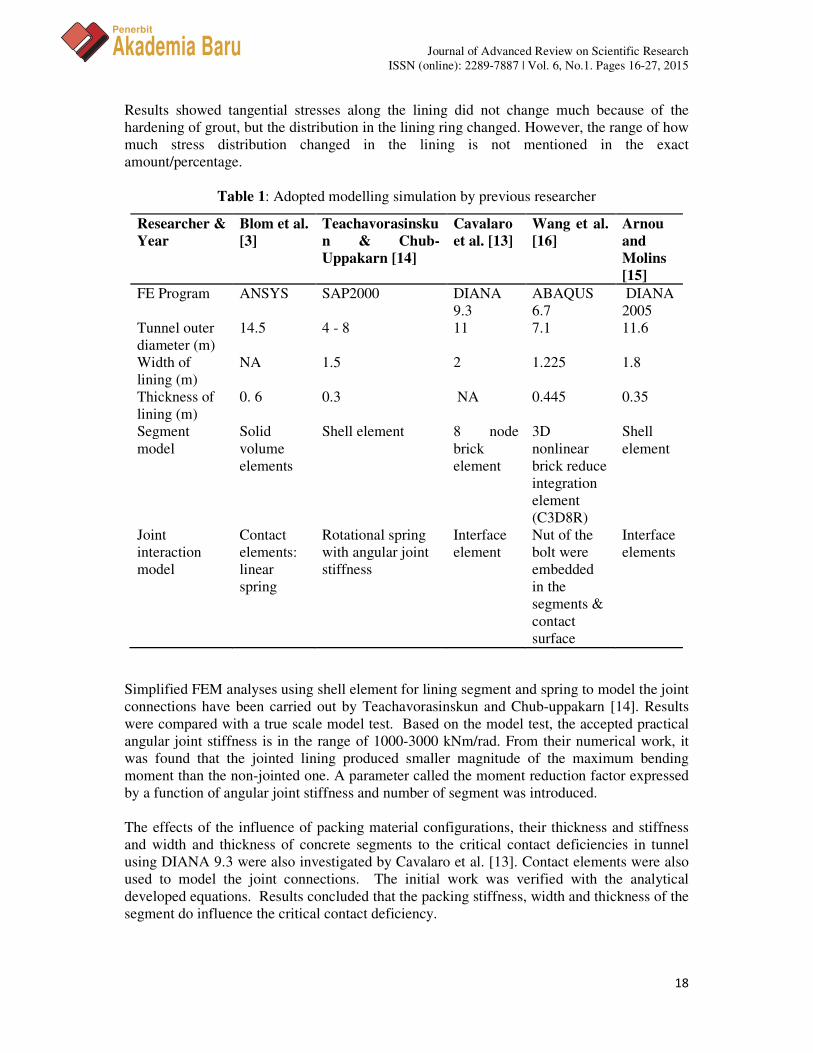
Figure 1 shows the model of single and dual jointed segments with 48850 numbers of
elements. A pair of pedestals was introduced at two ends to simulate the complicated
boundary condition of longitudinal seam. In the case of dual segments jointed by curved
bolts, the curved bolt modelling is assigned with tie constraint interaction.
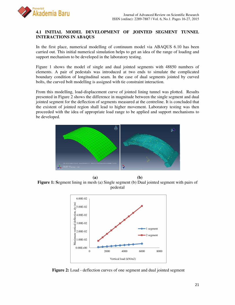
From this modelling, load-displacement curve of jointed lining tunnel was plotted. Results
presented in Figure 2 shows the difference in magnitude between the single segment and dual
jointed segment for the deflection of segments measured at the centreline. It is concluded that
the existent of jointed region shall lead to higher movement. Laboratory testing was then
proceeded with the idea of appropriate load range to be applied and support mechanisms to
be developed.
(a) (b) Figure 1: Segment lining in mesh (a) Single segment (b) Dual jointed segment with pairs of
pedestal
Figure 2: Load - deflection curves of one segment and dual jointed segment
0.00E+00
1.00E-02
2.00E-02
3.00E-02
4.00E-02
5.00E-02
6.00E-02
0 2000 4000 6000 8000
Maxim
um
ver
tica
l d
efle
cti
on
, d
y (
m)
Vertical load (kN/m2)
1 segment
2 segment

Journal of Advanced Review on Scientific Research
ISSN (online): 2289-7887 | Vol. 6, No.1. Pages 16-27, 2015
22
Penerbit
Akademia Baru
4.2 LABORATORY TESTING WORK
Flexural bending test using appropriate hogging segments taken from the nearby factory has
been carried out. Reinforced concrete lining specimen with 67.5o of hogging angle, almost
3.5 m span, 1.4 m width, 3.175 m outside radius and 0.275 m thickness was prepared.
As concrete is not a perfectly half rounded shape, a support system was developed to make
sure the edge of the segment lies comfortably in the testing area. The support system was
fabricated using the combination of simply supported steel beam to form triangular shape
(Figure 3). In the first experiment (Phase 1), one of the supports, i.e. 1.4 meters long of three
steel rollers (i.e., roller support on the right) was designed in such way that it could slide
horizontally while the other end (on the left) is bolted to the floor to function as a pin support.
The roller steel was applied with grease roller to function as a roller support. At the left
support is a steel box with 2 m anchored steel bolted to the floor. The triangle steel beam is
also supported laterally by H-beams to minimize the triangular beam translation during the
testing. To attach the segment to the triangle steel beam, the specially designed wall plug of
220 mm length and 50 mm thread with a diameter of 25 mm was used to help fixed the
segment in position and to the hole of triangle steel beam support system.
Testing was carried out using a Dartec hydraulic ram with a load-controlled system. A two-
point vertical load (using a frame extension redistribute as strip loading), imitating the
localised ground static load was applied to the middle of the segment. A 200 tonne of load
cell are attached with a computerized system used to verify the applied load from the
hydraulic ram of system. The strain gauges were properly mounted onto test specimen both
extrados and intrados of segment. At the same time, LVDTs were mounted at locations with
higher anticipated movement. Translation readings at the support system were also being
monitored.
Tests were performed initially within the elastic region. In reality, a full ring of tunnel would
consist of 5 to 8 segments jointed together. The joints allow the tunnel either to flex inward or
outward, thus allowing the tunnel to stay in a good service. In the first stage, the first tunnel
segment was laid as Pin-Roller and applied with load system (i.e., later known as non-jointed
pin-roller test, NJPR) shown in Figure 3. In the pin-roller testing, a triangle steel support of
one side was allowed to move to imitate hinge joint interaction. Three different load series,
beginning within the “elastic” loading (i.e., Test 1), continued with double the amount of
initial loading stage (Test 2) and finally loading to failure (Test 3).
In Phase 2, a non-jointed pin-pin test (NJPP) was performed (Figure 4). For NJPP test, a
triangle steel support of one side (which previously allowed moving) was then fixed with
bolted floor anchor and H-beam. This was carried out to imitate the almost rigid ground
condition surrounding the tunnel. Similarly, the incremental loading has been applied up to
130 kN (Test 1) (i.e., "elastic" loading) and 300 kN (Test 2) and the performance of segment
was investigated. Strains at intrados and extrados of segment surface were measured. Both of
the results are analysed in the next section.
Journal of Advanced Review on Scientific Research
ISSN (online): 2289-7887 | Vol. 6, No.1. Pages 16-27, 2015
23
Penerbit
Akademia Baru
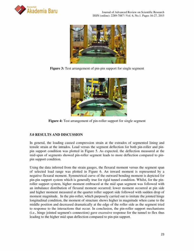
Figure 3: Test arrangement of pin-pin support for single segment
Figure 4: Test arrangement of pin-roller support for single segment 5.0 RESULTS AND DISCUSSION
In general, the loading caused compression strain at the extrados of segmented lining and
tensile strain at the intrados. Load versus the segment deflection for both pin-roller and pin-
pin support condition was plotted in Figure 5. As expected, the deflection measured at the
mid-span of segments showed pin-roller segment leads to more deflection compared to pin-
pin support condition.
Using the data inferred from the strain gauges, the flexural moment versus the segment span
of selected load range was plotted in Figure 6. An inward moment is represented by a
negative flexural moment. Symmetrical curve of the outward bending moment is depicted for
pin-pin support system which is generally true for rigid tunnel condition. Whilst, for the pin-
roller support system, higher moment embraced at the mid span segment was followed with
an imbalance distribution of flexural moment occurred; lower moment occurred at pin side
and higher moment measured at the quarter roller support side followed with sudden drop of
moment magnitude. In the pin-roller, which purposely carried out to imitate the jointed hinge
longitudinal condition, the moment of structure shows higher in magnitude when came to the
middle position and decreased dramatically at the edge of the roller side as the segment tried
to response to the interactions that occur. In conclusion, the pin-roller support mechanisms
(i.e., hinge jointed segment's connection) gave excessive response for the tunnel to flex thus
leading to the higher mid span deflection compared to pin-pin support.

Journal of Advanced Review on Scientific Research
ISSN (online): 2289-7887 | Vol. 6, No.1. Pages 16-27, 2015
24
Penerbit
Akademia Baru
Figure 7 and Figure 8 are the comparisons of results of the bending moment diagram
calculated using FEM and laboratory data of non-jointed single segment with pin-pin support
(NJPP) and non-jointed single segment with pin-roller support (NJPR) for load of 100 kN,
respectively. FEM showed continuous plotted moment diagram for the segment in the whole
segment span which gave more accurate moment reaction when compared to laboratory
results (i.e., only few points measured). The pin-pin segment reaction shows mirror pattern to
the middle of segment. In contrary, the pin-roller segment reaction shows a different flexural
movement in the segment at roller side. The moment was initially lower (i.e. bending inward)
then increased gradually to the midst of segment and reached its peak followed by the
decreasing moment magnitude and reached zero towards the roller support. It is also found
that the triangle support model of the segments in laboratory gave effect to the overall results.
Therefore, the appropriate model of support and material property model have been carefully
adopted in FEM to represent the real laboratory settings condition.
Figure 5: Load vs. deflection at mid span of segment
Figure 6: Bending moment for non-jointed pin-roller test (NJPR) and non-jointed pin-pin
test (NJPP) of single segment
0
20
40
60
80
100
120
140
0 0.002 0.004 0.006 0.008
Load
(kN
)
Deflection (m)
Pin-pin One Segment
Pin-roller One Segment
-5000
0
5000
10000
15000
20000
25000
0 1 2 3 4Ben
din
g m
om
ent,
M (
Nm
)
Segment's span length, x (m)
NJPR P = 50 kN
NJPR P = 100 kN
NJPP P = 50 kN
NJPP P = 100 kN

Journal of Advanced Review on Scientific Research
ISSN (online): 2289-7887 | Vol. 6, No.1. Pages 16-27, 2015
25
Penerbit
Akademia Baru
Figure 7: Bending moment for pin-pin support condition (NJPP) with numerical modelling
result (FEM-NJPP) of single segment
Figure 8: Bending moment for pin-roller support condition (NJPR) with numerical
modelling result (FEM-NJPR) of single segment
6.0 CONCLUSSION
A review on the previous experimental and numerical studies on the segmental concrete
tunnel lining was presented. The initial 3D simulation modelling by the authors was
presented in this paper. A series of laboratory testing of the segmented tunnel lining had been
carried out to conduct a flexural test. The load was applied on an arch configuration of the
tunnel lining to record the movements of the segment in elastic-plastic range and to
understand the flexural moment deflection response in the tunnel segments. In conclusion,
results show compression strain measured at the extrados and tensile strain measured at the
intrados of the segmented lining. The measured curvatures and deflections are nonlinearly
changed with the increased of applied loads. From the strain measurements, tangential
bending moments were calculated. A mirror curve of the tangential bending moment is
shown in the pin-pin support system while in pin-roller support, the lining reacts in contrary.
An unsymmetrically response of the flexural bending moment has occurred in the pin-roller
with the highest bending moment is measured at the near mid span of the lining to the side of
-1.50E+04
-1.00E+04
-5.00E+03
0.00E+00
5.00E+03
1.00E+04
1.50E+04
2.00E+04
2.50E+04
3.00E+04
0 1 2 3 4
Ben
din
g m
om
ent,
M (
Nm
)
Segment's pan length, x (m)
NJPP P = 100 kN
FEM-NJPP P=100 kN
-1.50E+04
-1.00E+04
-5.00E+03
0.00E+00
5.00E+03
1.00E+04
1.50E+04
2.00E+04
2.50E+04
3.00E+04
3.50E+04
4.00E+04
0 1 2 3 4
Ben
din
g m
om
ent,
M (
Nm
/m)
Segment's span length, x (m)
NJPP P=100 kN
FEM-NJPR P=100 kN

Journal of Advanced Review on Scientific Research
ISSN (online): 2289-7887 | Vol. 6, No.1. Pages 16-27, 2015
26
Penerbit
Akademia Baru
the roller support. These indicate that lining with appropriate joints (i.e., pin-pin) could help
reduce the maximum moment but excessive allowable joint movement (i.e., pin-roller) could
lead to higher moment which could endanger the structure stability. In addition, this research
aims to understand the appropriate characteristics of the tunnel response especially related to
ground load surrounding effects which are essential for long-term safety measurements.
Further study is on-going to take into account of the joint interactions for both longitudinal
and circumferential seam of lining.
REFERENCES
[1] Y. Koyama, Present status and technology of shield tunneling method in Japan,
Tunnelling and Underground Space Technology 18 (2003) 145-159.
[2] C.B.M. Blom, E.J. van der Horst, P.S. Jovanovic, Three-dimensional structural analyses
of the shield-driven Green Heart tunnel of the high-speed line South, Tunnelling and
Underground Space Technology 14 (1999) 217-224.
[3] M. Sugimoto, Causes of shield segment damages during construction, International
Symposium on Underground Excavation and Tunnelling, Bangkok, Thailand (2006).
[4] J. Chen, H. Mo, Numerical study on crack problems in segments of shield tunnel using
finite element method, Tunnelling and Underground Space Technology 24 (2009) 91-
102.
[5] C. Sagaseta, Analysis of undrained soil deformation due to ground loss, Geotechnique
37 (1987) 301-320.
[6] A. Verruijt, J.R. Booker, Surface settlements due to the deformation of a tunnel in an
elastic half plane, Geotechnique 46 (1996) 753-756.
[7] N. Loganathan, and H.G. Poulos, Analytical prediction for tunneelling-induced ground
movements in clays, Journal of Geotechnical and Geoenvironmental Engineering 124
(1998) 846-856.
[8] K.H. Park. Elastic Solution for Tunneling-Induced Ground Movements in Clays,
International Journal of Geomechanics 4 (2004) 310.
[9] S.H. Kim, Model Testing and Analysis of Interactions between Tunnels in Clay, PhD
Thesis, University of Oxford (1996).
[10] S.M. Liao, F.E. Peng, S.L. Shen, Analysis of shearing effect on a tunnel induced by
load transfer along longitudinal direction, Tunnelling and Underground Space
Technology 23 (2008) 421-430.
[11] H. Mohamad, K. Soga, P.J. Bennett, R.J. Mair, S.L. Chi, Monitoring twin tunnel
interaction using distributed optical fiber strain measurements, Journal of Geotechnical
and Geoenvironmental Engineering 138 (2012) 957-967.

Journal of Advanced Review on Scientific Research
ISSN (online): 2289-7887 | Vol. 6, No.1. Pages 16-27, 2015
27
Penerbit
Akademia Baru
[12] J. Chen, H. Mo, Numerical study on crack problems in segments of shield tunnel using
finite element method, Tunnelling and Underground Space Technology 24 (2009) 91-
102.
[13] S.H.P. Cavalaro, C.B.M. Blom, J.C. Walrave, A. Aguado, Packer behaviour under
simple and coupled stresses, Tunnelling and Underground Space Technology 28 (2011)
159-173.
[14] S. Teachavorasinskun, S. Chub-uppakarn, Influence of segmental joints on tunnel
lining, Tunnelling and Underground Space Technology 25 (2010) 490-494.
[15] O. Arnau, C. Molins, Experimental and analytical study of the structural response of
segmental tunnel linings based on an in situ loading test, Part 2: Numerical simulation,
Tunnelling and Underground Space Technology 26 (2011b) 778-788.
[16] L.Z. Wang, Z. Wang, L.L. Li, J.C. Wang, Construction behavior simulation of a
hydraulic tunnel during standpipe lifting, Tunnelling and Underground Space
Technology 26 (2011) 674-685.
[17] O. Arnau, C. Molins, Experimental and analytical study of the structural response of
segmental tunnel linings based on an in situ loading test, Part 1: Test configuration and
Execution, Tunnelling and Underground Space Technology 26 (2011a) 764-777.
[18] K. Nishikawa, Development of a prestressed and precast concrete segmental lining,
Tunnelling and Underground Space Technology 18 (2003) 243-251.
[19] A. Caratelli, Meda, Z. Rinaldi, P. Romualdi, Structural behaviour of precast tunnel
segments in fiber reinforced concrete, Tunnelling and Underground Space Technology
26 (2011) 284-291.