pre-formance - graybar€¦ · pre-formance™ table of contents 2 3 product description page boxes...
TRANSCRIPT

Pre-formance™
Giving you the convenience of a pre-fabricated product—plus the flexibility to accommodate job-site requirements
CHEC_45234_PreFormance_Bro.indd 1 1/15/08 11:52:05 AM
IEC 309 Non-Metallic Plugs, Receptacles & InterlocksPRE-formance™
32
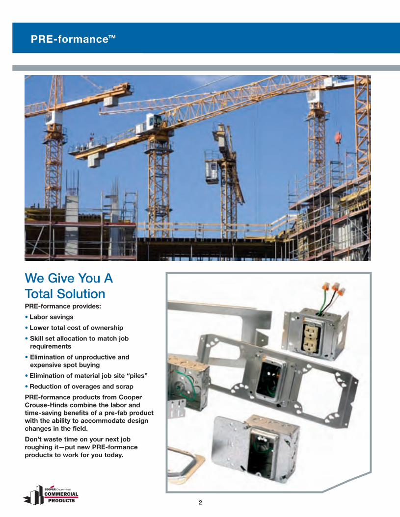
We Give You A Total Solution PRE-formance provides:
• Labor savings
• Lower total cost of ownership
• Skill set allocation to match job requirements
• Elimination of unproductive and expensive spot buying
• Elimination of material job site “piles”
• Reduction of overages and scrap
PRE-formance products from Cooper Crouse-Hinds combine the labor and time-saving benefits of a pre-fab product with the ability to accommodate design changes in the field.
Don’t waste time on your next job roughing it—put new PRE-formance products to work for you today.
CHEC_45234_PreFormance_Bro.indd 2 1/15/08 11:52:11 AM

PRE-formance™ Table of Contents
32
Product Description Page
Boxes with Pre-installed Ground Screw & Pigtail
Choose from our wide selection of outlet boxes with ground screw and pigtail lead—available from stock!
4
Fire Alarm Boxes Meet the NEC® requirements for fire circuit identification with the convenience and the savings of PRE-formance
5
4" Square Bracketed Outlet Boxes
Bracketed boxes offer quick and easy installation onto either side of a steel stud
6
Uni-Mount™ Covers & Assemblies
Provides a secure box support with built-in plaster ring 7 & 8
Telescoping Slider Assemblies
Adjustable pre-fab bracket for mounting between studs 9
Floor Mount Assemblies Sturdy and flexible. Positions center of box 15", 18" or 24" above floor
10
Floor Mount Slider Combo Assemblies
Sturdy and flexible. Positions center of box 15", 18" or 24" above floor
11
Single & Double Sided Box Support Assemblies
Labor-saving, built-in and adjustable far-side supports, double sided box support can be installed on either side of stud without repositioning
12
Multiple Box Mounting Assemblies
Provides support for multiple boxes or plaster rings 13
Open Box Support Mounting Assemblies
Provides adjustable support for multiple boxes or plaster rings
14
T-Bar Fasteners Assemblies
Provides box support between T-bar rails 15
Custom Assemblies Customize an assembly to meet your specific job requirements
16-19
CHEC_45234_PreFormance_Bro.indd 3 1/15/08 11:52:23 AM
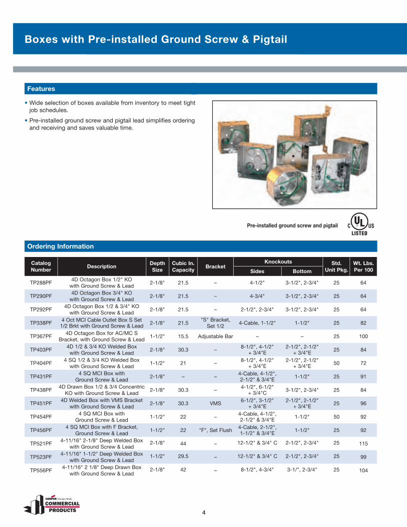
Boxes with Pre-installed Ground Screw & Pigtail
5
Features
• Wide selection of boxes available from inventory to meet tight job schedules.
• Pre-installed ground screw and pigtail lead simplifies ordering and receiving and saves valuable time.
Pre-installed ground screw and pigtail
4
Catalog Number
DescriptionDepthSize
Cubic In. Capacity
BracketKnockouts Std.
Unit Pkg.Wt. Lbs.Per 100Sides Bottom
TP288PF4D Octagon Box 1/2" KO
with Ground Screw & Lead2-1/8" 21.5 – 4-1/2" 3-1/2", 2-3/4" 25 64
TP290PF4D Octagon Box 3/4" KO
with Ground Screw & Lead2-1/8" 21.5 – 4-3/4" 3-1/2", 2-3/4" 25 64
TP292PF4D Octagon Box 1/2 & 3/4" KO
with Ground Screw & Lead2-1/8" 21.5 – 2-1/2", 2-3/4" 3-1/2", 2-3/4" 25 64
TP338PF 4 Oct MCI Cable Outlet Box S Set 1/2 Brkt with Ground Screw & Lead 2-1/8" 21.5
"S" Bracket, Set 1/2
4-Cable, 1-1/2" 1-1/2" 25 82
TP367PF4D Octagon Box for AC/MC S
Bracket, with Ground Screw & Lead1-1/2" 15.5 Adjustable Bar – – 25 100
TP403PF4D 1/2 & 3/4 KO Welded Box
with Ground Screw & Lead2-1/8" 30.3 – 8-1/2", 4-1/2"
+ 3/4"E2-1/2", 2-1/2"
+ 3/4"E 25 84
TP404PF4 SQ 1/2 & 3/4 KO Welded Box
with Ground Screw & Lead1-1/2" 21 – 8-1/2", 4-1/2"
+ 3/4"E2-1/2", 2-1/2"
+ 3/4"E 50 72
TP431PF4 SQ MCI Box with
Ground Screw & Lead2-1/8" – – 4-Cable, 4-1/2",
2-1/2" & 3/4"E 1-1/2" 25 91
TP438PF4D Drawn Box 1/2 & 3/4 Concentric
KO with Ground Screw & Lead2-1/8" 30.3 – 4-1/2", 6-1/2"
+ 3/4"C 3-1/2", 2-3/4" 25 84
TP451PF4D Welded Box with VMS Bracket
with Ground Screw & Lead2-1/8" 30.3 VMS 6-1/2", 3-1/2"
+ 3/4"E2-1/2", 2-1/2"
+ 3/4"E 25 96
TP454PF4 SQ MCI Box with
Ground Screw & Lead1-1/2" 22 – 4-Cable, 4-1/2",
2-1/2" & 3/4"E 1-1/2" 50 92
TP456PF4 SQ MCI Box with F Bracket,
Ground Screw & Lead1-1/2" 22 "F", Set Flush 4-Cable, 2-1/2",
1-1/2" & 3/4"E 1-1/2" 25 92
TP521PF4-11/16" 2-1/8" Deep Welded Box
with Ground Screw & Lead2-1/8" 44 – 12-1/2" & 3/4" C 2-1/2", 2-3/4" 25 115
TP523PF4-11/16" 1-1/2" Deep Welded Box
with Ground Screw & Lead1-1/2" 29.5 – 12-1/2" & 3/4" C 2-1/2", 2-3/4" 25 99
TP556PF4-11/16" 2 1/8" Deep Drawn Box
with Ground Screw & Lead2-1/8" 42 – 8-1/2", 4-3/4" 3-1/", 2-3/4" 25 104
Ordering Information
CHEC_45234_PreFormance_Bro.indd 4 1/15/08 11:52:26 AM

Fire Alarm Boxes
54
• Red epoxy paint allows for quick identification of fire alarm systems meeting NEC requirements.
• Eliminate the need to paint boxes on the job site, saving time and expense.
• Available in 4" and 4-11/16" square and 4" octagon, 1-1/2" and 2-1/8" deep welded or drawn construction and with extension rings to meet customer requirements or preferences.
Features
TP292reD
TP451reD
TP568reDTP564reDTP556reDTP472reDTP428reD
TP403reDTP434reDTP414reDTP423reDTP404reD
Catalog Number
DescriptionDepthSize
Cubic In. Capacity
BracketKnockouts Std.
Unit Pkg.Wt. Lbs.Per 100Sides Bottom
TP404RED 4" Sq Box Shallow Welded 1-1/2" 22 – 8-1/2", 4-1/2" & 3/4" E
2-1/2", 2-1/2" & 3/4" E 50 72
TP423RED 4" Sq Box Shallow Welded 1-1/2" 22 VMS 6-1/2", 3-1/2" & 3/4" E
2-1/2", 2-1/2" & 3/4" E 25 81
TP414RED 4" Sq Box Shallow Drawn 1-1/2" 21 – 8-1/2", 4-3/4" 3-1/2", 2-3/4" 50 67
TP434RED 4" Sq Deep Drawn 1-1/2" 30.3 – 8-1/2", 4-3/4" 3-1/2", 2-3/4" 25 84
TP403RED 4" Sq Box Deep Welded 2-1/8" 30.3 – 8-1/2", 4-1/2" & 3/4" E
2-1/2", 2-1/2" & 3/4" E 25 84
TP451RED 4" Sq Box Deep Welded 2-1/8" 30.3 VMS 6-1/2", 3-1/2" & 3/4" E
2-1/2", 2-1/2" & 3/4" E 25 96
TP428RED 4" Sq Extension Ring 1-1/2" 21 – 8-1/2", 4-3/4" – 50 46
TP472RED 4" Sq Flat Blank Cover – – – – – 50 31
TP556RED 4-11/16" Sq Box Deep 2-1/8" 42 – 8-1/2", 4-3/4" 3-1/2", 2-3/4" 25 104
TP564RED 4-11/16" Sq Extension Ring 2-1/8" 42 – 8-1/2", 4-3/4" – 25 84
TP568RED 4-11/16" Sq Flat Blank Cover – – – – – 25 40
TP292RED 4" Octagon Deep Outlet Box 2-1/8" 21.5 – 2-1/2", 2-3/4" 3-1/2", 2-3/4" 25 64
Ordering Information
CHEC_45234_PreFormance_Bro.indd 5 1/15/08 11:52:35 AM

4" Square Bracketed Outlet Boxes
Bracketed boxes offer quick and easy installation onto either side of a steel stud. For use with conduit, armored/metal clad cable or non-metallic sheathed cable.
Catalog Number*
Box Size Box Depth For Use WithCubic Inch Capacity
Description
Sides Bottom
TP404SSB 4" 1-1/2" Conduit 22 8-1/2", 4-1/2" & 3/4" E 2-1/2", 2-1/2" & 3/4" E
TP444SSB 4" 1-1/2" Non-metallic Sheathed Cable 22 4 Cable, 4-1/2", 2-1/2" &
3/4" E 1-1/2"
TP454SSB 4" 1-1/2" Armored/Metal Clad Cable 22 4 Cable, 4-1/2", 2-1/2" &
3/4" E 1-1/2"
TP403SSB 4" 2-1/8" Conduit 30.3 8-1/2", 4-1/2" & 3/4" E 2-1/2", 2-1/2" & 3/4" E
TP450SSB 4" 2-1/8" Non-metallic Sheathed Cable 30.3 4 Cable, 4-1/2", 2-1/2" &
3/4" E 1-1/2"
TP431SSB 4" 2-1/8" Armored/Metal Clad Cable 30.3 4 Cable, 4-1/2", 2-1/2" &
3/4" E 1-1/2"
TP563SSB 4-11/16" 2-1/8" Conduit 42 6-1/2", 6-1/2" & 3/4" C 3-1/2", 2-3/4"
* to include ground screw with 8" solid pigtail ground lead, add suffix "PF" to catalog number. Example: TP404SSBPF
6 7
Features
• Special spring steel allows for quick and easy tool-free installation.
• Mounts on either side of the stud and can be easily removed or repositioned.
• Sleek, low profile mounting bracket.
• Far side support bracket provides support for boxes in 2-1/4"–4" studs.
• Far side support snaps easily onto box and is secured in place by plaster ring.
• Available in shallow and deep boxes for use with conduit, armored/metal clad cable or non-metallic sheathed cable.
TP404SSB TP444SSB TP454SSB TP403SSB TP450SSB TP431SSB TP563SSB
Ordering Information
CHEC_45234_PreFormance_Bro.indd 6 1/15/08 11:52:39 AM

Uni-Mount™ Covers
6 7
Single Gang Two Gang
The Uni-Mount combines the features of a mounting device plate with those of a box support, giving you one universal plate for all your needs. Specifically designed for use with metal and wood studs:
• Universal design fits all 4" square boxes.
• Guide tabs ensure consistent alignment on stud.
• Stud alignment hole ensures consistent mounting height.
• Rigid bracket design eliminates the need for far side support.
• Available as a single or two device cover.
• Available in 1/2", 5/8" and 3/4" raised.
• Fast and easy installation.
• Can be used in multiple applications, resulting in less items to stock.
• Less labor intensive.
• Less material handling.
• No multiple assemblies to handle.
• Can be used in Class 2 communications outlets for low voltage without a box.
• UL Listed and CSA certified.*
Catalog Number Description Capacity Cu. In. Std. Unit Pkg. Wt. Lbs. Per 100
SINGLE GANG
TP30000 1/2" Raised 3.8 50 43
TP31000 5/8" Raised 4.3 50 46
TP32000 3/4" Raised 5.5 50 50
TWO GANG
TP35000 1/2" Raised 6 50 38
TP36000 5/8" Raised 8 50 52
TP37000 3/4" Raised 9 50 54
LOW PROFILE SCREWS—reduces risk of sheet rock bulge
TP710 L.P. Screws — 1000 .5
* CSA requires a far side support.
Ordering Information
R
CHEC_45234_PreFormance_Bro.indd 7 1/15/08 11:52:42 AM

Uni-Mount™ Assemblies
TP404 1-1/2" Deep–Welded 22" Cubic Capacity
TP403 21/8" Deep–Welded22" Cubic Capacity
TP436 2-1/8" Deep–Welded30.3" Cubic Capacity
TP467 1-1/2" Deep–Welded22" Cubic Capacity
TP414 1-1/2" Deep–Welded21" Cubic Capacity
TP434 2-1/8" Deep–Welded30.3" Cubic Capacity
TP454 1-1/2" Deep–Welded22" Cubic Capacity
TP431 2-1/8" Deep–Welded30.3" Cubic Capacity
• Uni-Mount provides a secure box support and features a built-in plaster ring.
• Can be field assembled with outlet box for power applications or used without a box for low voltage applications.
• Pre-fab Uni-Mount is available with most popular outlet boxes with a choice of 1/2", 5/8" or 3/4" raised cover and includes ground screw and lead.
• Rigid bracket design eliminates the need for far-side support.
• Guide tabs ensure alignment on studs.
8 9
Features
Catalog Number
Description Pre-Fabricated Box and Cover (no ground screw or lead)
Capacity Cu. In.
Std. Unit Pkg.
Wt. Lbs. Per 100
For ConduitTP30414 1-1/2" Drawn Box assembled to 1/2" Raised Single Gang Uni-Mount Cover 24.8 25 110TP31414 1-1/2" Drawn Box assembled to 5/8" Raised Single Gang Uni-Mount Cover 25.3 25 113TP32414 1-1/2" Drawn Box assembled to 3/4" Raised Single Gang Uni-Mount Cover 26.5 25 117TP35414 1-1/2" Drawn Box assembled to 1/2" Raised Two Gang Uni-Mount Cover 27 25 105TP36414 1-1/2" Drawn Box assembled to 5/8" Raised Two Gang Uni-Mount Cover 29 25 119TP37414 1-1/2" Drawn Box assembled to 3/4" Raised Two Gang Uni-Mount Cover 30 25 121TP30434 2-1/8" Drawn Box assembled to 1/2" Raised Single Gang Uni-Mount Cover 34.1 25 127TP31434 2-1/8" Drawn Box assembled to 5/8" Raised Single Gang Uni-Mount Cover 34.6 25 130TP32434 2-1/8" Drawn Box assembled to 3/4" Raised Single Gang Uni-Mount Cover 35.8 25 134TP35434 2-1/8" Drawn Box assembled to 1/2" Raised Two Gang Uni-Mount Cover 36.3 25 122TP36434 2-1/8" Drawn Box assembled to 5/8" Raised Two Gang Uni-Mount Cover 38.3 25 136TP37434 2-1/8" Drawn Box assembled to 3/4" Raised Two Gang Uni-Mount Cover 39.3 25 138
For AC/MC CableTP30454 1-1/2" Welded Box assembled to 1/2" Raised Single Gang Uni-Mount Cover 24.8 25 114TP31454 1-1/2" Welded Box assembled to 5/8" Raised Single Gang Uni-Mount Cover 25.3 25 117TP32454 1-1/2" Welded Box assembled to 3/4" Raised Single Gang Uni-Mount Cover 26.5 25 121TP35454 1-1/2" Welded Box assembled to 1/2" Raised Two Gang Uni-Mount Cover 27 25 109TP36454 1-1/2" Welded Box assembled to 5/8" Raised Two Gang Uni-Mount Cover 29 25 123TP37454 1-1/2" Welded Box assembled to 3/4" Raised Two Gang Uni-Mount Cover 30 25 125TP30431 2-1/8" Welded Box assembled to 1/2" Raised Single Gang Uni-Mount Cover 34.1 25 134TP31431 2-1/8" Welded Box assembled to 5/8" Raised Single Gang Uni-Mount Cover 34.6 25 137TP32431 2-1/8" Welded Box assembled to 3/4" Raised Single Gang Uni-Mount Cover 35.8 25 141TP35431 2-1/8" Welded Box assembled to 1/2" Raised Two Gang Uni-Mount Cover 36.3 25 129TP36431 2-1/8" Welded Box assembled to 5/8" Raised Two Gang Uni-Mount Cover 38.3 25 143TP37431 2-1/8" Welded Box assembled to 3/4" Raised Two Gang Uni-Mount Cover 39.3 25 145
Pre-Fabricated Box, Cover, Ground Screw and Lead Assembly (with ground screw and lead)
For ConduitTP30404PF 1-1/2" Welded Box, 1/2" Raised Single Gang Uni-Mount Cover, ground screw and lead 25.8 25 115TP31404PF 1-1/2" Welded Box, 5/8" Raised Single Gang Uni-Mount Cover, ground screw and lead 26.3 25 118TP31436PF 2-1/8" Welded Box, 5/8" Raised Single Gang Uni-Mount Cover, ground screw and lead 34.6 25 130TP31467PF 1-1/2" Welded Box, 5/8" Raised Single Gang Uni-Mount Cover, ground screw and lead 26.3 25 113TP32404PF 1-1/2" Welded Box, 3/4" Raised Single Gang Uni-Mount Cover, ground screw and lead 27.5 25 122TP32454PF 1-1/2" Welded Box, 3/4" Raised Single Gang Uni-Mount Cover, ground screw and lead 27.5 25 121TP35404PF 1-1/2" Welded Box, 1/2" Raised Two Gang Uni-Mount Cover, ground screw and lead 28 25 110TP36404PF 1-1/2" Welded Box, 5/8" Raised Two Gang Uni-Mount Cover, ground screw and lead 30 25 124TP36467PF 1-1/2" Welded Box, 5/8" Raised Two Gang Uni-Mount Cover, ground screw and lead 30 25 119TP37404PF 1-1/2" Welded Box, 3/4" Raised Two Gang Uni-Mount Cover, ground screw and lead 31 25 126TP30403PF 2-1/8" Welded Box, 1/2" Raised Single Gang Uni-Mount Cover, ground screw and lead 34.1 25 107TP31403PF 2-1/8" Welded Box, 5/8" Raised Single Gang Uni-Mount Cover, ground screw and lead 34.6 25 110TP32403PF 2-1/8" Welded Box, 3/4" Raised Single Gang Uni-Mount Cover, ground screw and lead 35.8 25 114TP35403PF 2-1/8" Welded Box, 1/2" Raised Two Gang Uni-Mount Cover, ground screw and lead 36.3 25 102TP36403PF 2-1/8" Welded Box, 5/8" Raised Two Gang Uni-Mount Cover, ground screw and lead 38.3 25 116TP37403PF 2-1/8" Welded Box, 3/4" Raised Two Gang Uni-Mount Cover, ground screw and lead 39.3 25 118
CHEC_45234_PreFormance_Bro.indd 8 1/15/08 11:52:47 AM
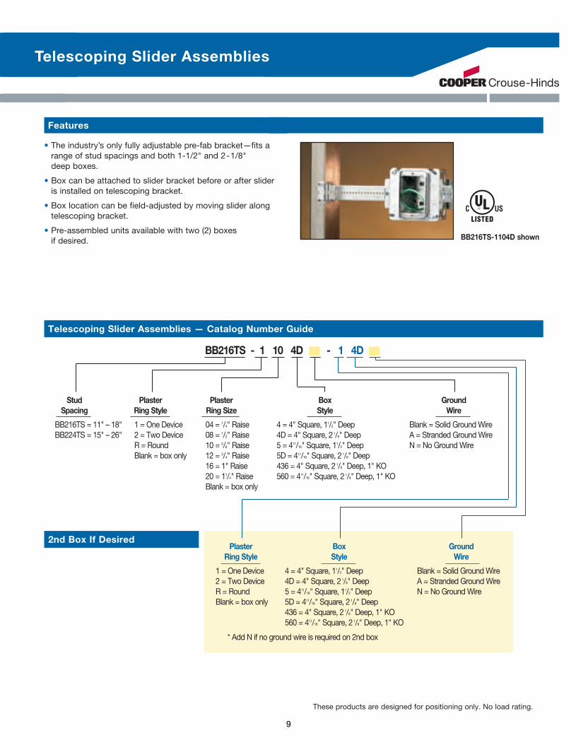
Telescoping Slider Assemblies
Features
• The industry’s only fully adjustable pre-fab bracket—fits a range of stud spacings and both 1-1/2" and 2-1/8" deep boxes.
• Box can be attached to slider bracket before or after slider is installed on telescoping bracket.
• Box location can be field-adjusted by moving slider along telescoping bracket.
• Pre-assembled units available with two (2) boxes if desired. BB216TS-1104D shown
Telescoping Slider Assemblies — Catalog Number Guide
BB216TS - 1 10 4D - 1 4D
Stud Plaster Plaster Box Ground Spacing Ring Style Ring Size Style Wire
BB216TS = 11" – 18" 1 = One Device 04 = 1/4" Raise 4 = 4" Square, 11/2" Deep Blank = Solid Ground WireBB224TS = 15" – 26" 2 = Two Device 08 = 1/2" Raise 4D = 4" Square, 2 1/8" Deep A = Stranded Ground Wire R = Round 10 = 5/8" Raise 5 = 411/16" Square, 11/2" Deep N = No Ground Wire Blank = box only 12 = 3/4" Raise 5D = 411/16" Square, 21/8" Deep 16 = 1" Raise 436 = 4" Square, 21/8" Deep, 1" KO 20 = 11/4" Raise 560 = 411/16" Square, 21/8" Deep, 1" KO Blank = box only
Plaster Box Ground Ring Style Style Wire
1 = One Device 4 = 4" Square, 11/2" Deep Blank = Solid Ground Wire2 = Two Device 4D = 4" Square, 2 1/8" Deep A = Stranded Ground WireR = Round 5 = 411/16" Square, 11/2" Deep N = No Ground WireBlank = box only 5D = 411/16" Square, 21/8" Deep 436 = 4" Square, 2 1/8" Deep, 1" KO 560 = 411/16" Square, 21/8" Deep, 1" KO
* Add N if no ground wire is required on 2nd box
2nd Box If Desired
8 9
These products are designed for positioning only. No load rating.
CHEC_45234_PreFormance_Bro.indd 9 1/15/08 11:52:50 AM
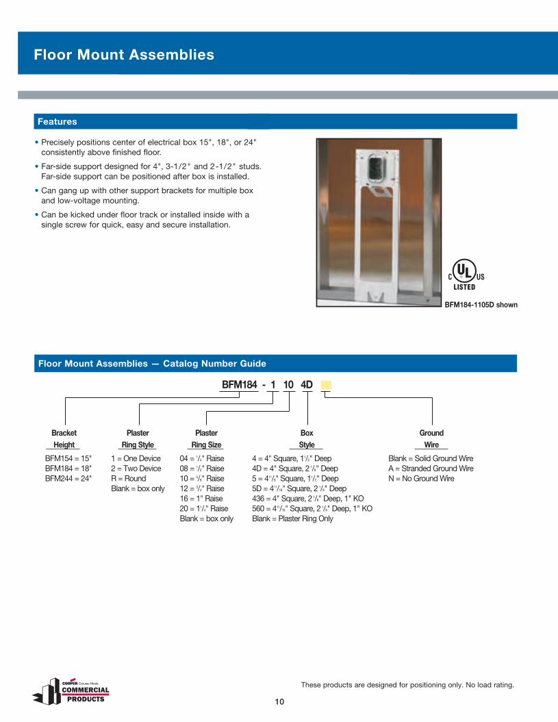
Floor Mount Assemblies
10
These products are designed for positioning only. No load rating.
11
Floor Mount Assemblies — Catalog Number Guide
• Precisely positions center of electrical box 15", 18", or 24" consistently above finished floor.
• Far-side support designed for 4", 3-1/2" and 2-1/2" studs. Far-side support can be positioned after box is installed.
• Can gang up with other support brackets for multiple box and low-voltage mounting.
• Can be kicked under floor track or installed inside with a single screw for quick, easy and secure installation.
BFM184-1105D shown
BFM184 - 1 10 4D
Bracket Plaster Plaster Box Ground Height Ring Style Ring Size Style Wire
BFM154 = 15" 1 = One Device 04 = 1/4" Raise 4 = 4" Square, 11/2" Deep Blank = Solid Ground WireBFM184 = 18" 2 = Two Device 08 = 1/2" Raise 4D = 4" Square, 2 1/8" Deep A = Stranded Ground WireBFM244 = 24" R = Round 10 = 5/8" Raise 5 = 411/8" Square, 11/2" Deep N = No Ground Wire Blank = box only 12 = 3/4" Raise 5D = 411/16" Square, 2 1/8" Deep 16 = 1" Raise 436 = 4" Square, 2 1/8" Deep, 1" KO 20 = 11/4" Raise 560 = 411/16" Square, 2 1/8" Deep, 1" KO Blank = box only Blank = Plaster Ring Only
Features
CHEC_45234_PreFormance_Bro.indd 10 1/15/08 11:52:52 AM
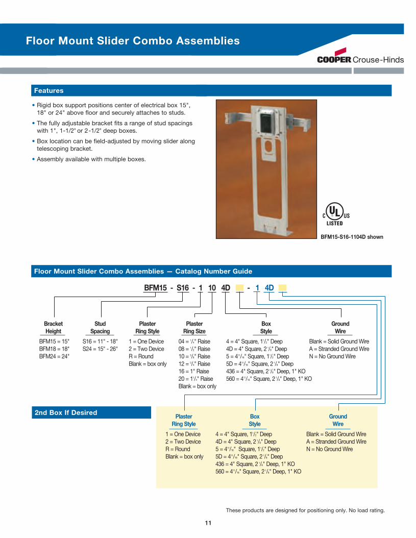
Floor Mount Slider Combo Assemblies
2nd Box If Desired
10
These products are designed for positioning only. No load rating.
11
BFM184-1105D shown
• Rigid box support positions center of electrical box 15", 18" or 24" above floor and securely attaches to studs.
• The fully adjustable bracket fits a range of stud spacings with 1", 1-1/2" or 2-1/2" deep boxes.
• Box location can be field-adjusted by moving slider along telescoping bracket.
• Assembly available with multiple boxes.
BFM15-S16-1104D shown
BFM15 - S16 - 1 10 4D - 1 4D
Bracket Stud Plaster Plaster Box Ground Height Spacing Ring Style Ring Size Style Wire
BFM15 = 15" S16 = 11" - 18" 1 = One Device 04 = 1/4" Raise 4 = 4" Square, 11/2" Deep Blank = Solid Ground WireBFM18 = 18" S24 = 15" - 26" 2 = Two Device 08 = 1/2" Raise 4D = 4" Square, 2 1/8" Deep A = Stranded Ground WireBFM24 = 24" R = Round 10 = 5/8" Raise 5 = 411/16" Square, 11/2" Deep N = No Ground Wire Blank = box only 12 = 3/4" Raise 5D = 411/16" Square, 21/8" Deep 16 = 1" Raise 436 = 4" Square, 2 1/8" Deep, 1" KO 20 = 11/4" Raise 560 = 411/16" Square, 21/8" Deep, 1" KO Blank = box only
Plaster Box Ground Ring Style Style Wire
1 = One Device 4 = 4" Square, 11/2" Deep Blank = Solid Ground Wire2 = Two Device 4D = 4" Square, 2 1/8" Deep A = Stranded Ground WireR = Round 5 = 411/16" Square, 11/2" Deep N = No Ground WireBlank = box only 5D = 411/16" Square, 21/8" Deep 436 = 4" Square, 2 1/8" Deep, 1" KO 560 = 411/16" Square, 21/8" Deep, 1" KO
Features
Floor Mount Slider Combo Assemblies — Catalog Number Guide
CHEC_45234_PreFormance_Bro.indd 11 1/15/08 11:52:52 AM

Single and Double Sided Box Support Assemblies
12 13
• Far-side support prevents box movement in wall cavity.
• Adjustable far-side supports designed to reduce labor. • BB4-6 works on 6", 5-1/2", 3-1/2", and 2-1/2" studs. • BB4-4 works on 4", 3-1/2", and 2-1/2" studs.
• Brackets may be piggy-backed in series or attached to Floor Mount Box Supports (see page 10). BB423-2104D shown
Features — Single Sided Assemblies
BB423 - 1 10 4D
Stud Plaster Plaster Box Ground Depth Ring Style Ring Size Style Wire
BB423 = 1 = One Device 04 = 1/4" Raise 4 = 4" Square, 11/2" Deep Blank = Solid Ground Wire31/2" & 2 1/2" 2 = Two Device 08 = 1/2" Raise 4D = 4" Square, 2 1/8" Deep A = Stranded Ground WireBB44 = R = Round 10 = 5/8" Raise 5 = 411/16" Square, 11/2" Deep N = No Ground Wire4", 31/2" & 2 1/2" Blank = box only 12 = 3/4" Raise 5D = 411/16" Square, 2 1/8" DeepBB46 = 16 = 1" Raise 436 = 4" Square, 21/8" Deep, 1" KO6", 51/2", 31/2" & 2 1/2" 20 = 11/4" Raise 560 = 411/16" Square, 2 1/8" Deep, 1" KO Blank = box only Blank = Plaster Ring Only
Single Side Assemblies — Catalog Number Guide
BB73 - 1 10 4D
Stud Plaster Plaster Box Ground Depth Ring Style Ring Size Style Wire
BB73 = 1 = One Device 04 = 1/4" Raise 4 = 4" Square, 11/2" Deep Blank = Solid Ground Wire3 1/2" & 2 1/2" 2 = Two Device 08 = 1/2" Raise 4D = 4" Square, 2 1/8" Deep A = Stranded Ground WireBB74 = R = Round 10 = 5/8" Raise 5 = 411/16" Square, 11/2" Deep N = No Ground Wire4", 3 1/2" & 2 1/2" Blank = box only 12 = 3/4" Raise 5D = 411/16" Square, 2 1/8" DeepBB76 = 16 = 1" Raise 436 = 4" Square, 2 1/8" Deep, 1" KO6", 5 1/2", 3 1/2" & 2 1/2" 20 = 11/4" Raise 560 = 411/16" Square, 2 1/8" Deep, 1" KO Blank = box only Blank = Plaster Ring Only
Double Sided Assemblies — Catalog Number Guide
• Double side box support designed for pre-fab installations. Unit can be installed on either side of stud without repositioning box or devices.
• Adjustable far-side supports designed to reduce labor. Three different sizes pre-bent for 3-1/2", 4" or 6" studs.
• Mounting bracket options accommodate stud depth from 2-1/2" – 6".
• Stands up to drywallers; far side supports prevent box movement in wall cavity.
BB73-1104D shown
Features — Double Sided Assemblies
These products are designed for positioning only. No load rating.
CHEC_45234_PreFormance_Bro.indd 12 1/15/08 11:52:56 AM
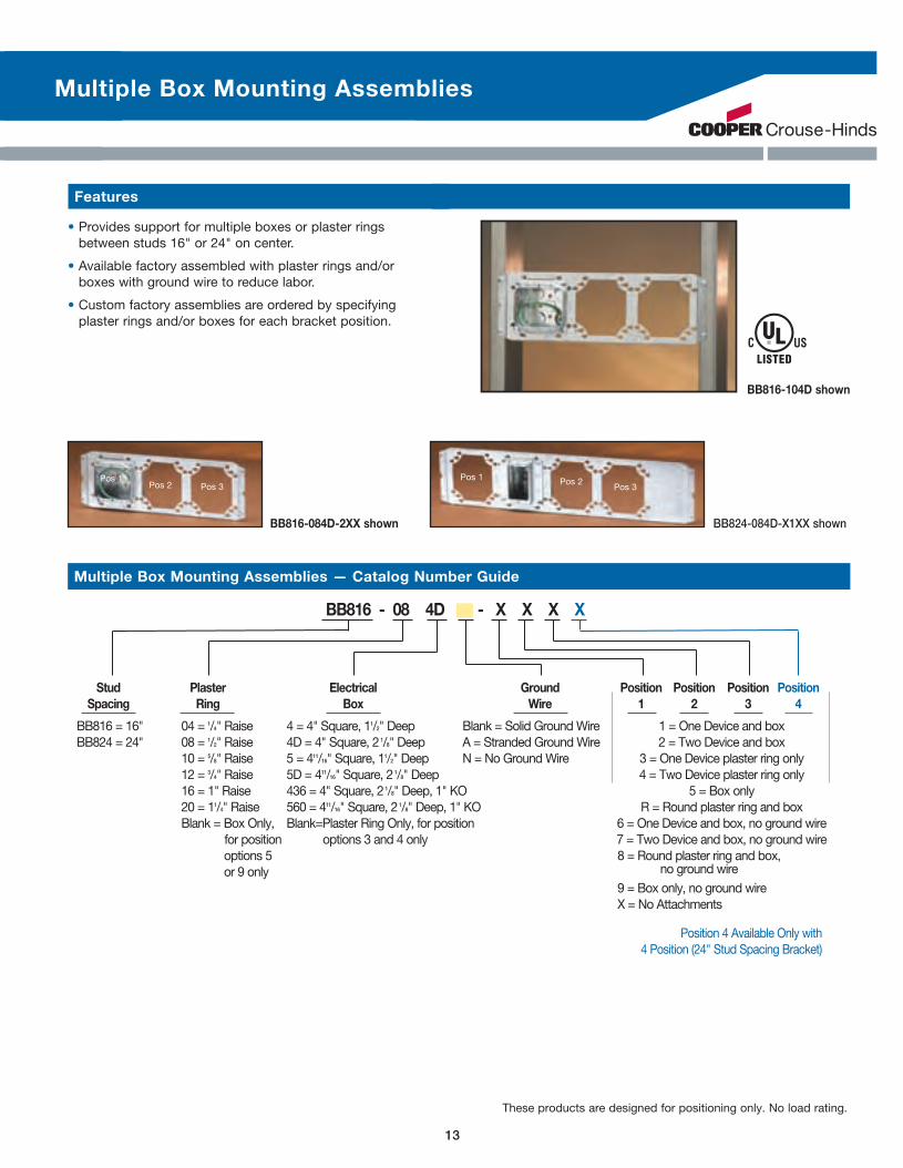
Multiple Box Mounting Assemblies
12 13
• Provides support for multiple boxes or plaster rings between studs 16" or 24" on center.
• Available factory assembled with plaster rings and/or boxes with ground wire to reduce labor.
• Custom factory assemblies are ordered by specifying plaster rings and/or boxes for each bracket position.
Features
BB816-104D shown
BB816-084D-2XX shown BB824-084D-X1XX shown
Pos 1Pos 2 Pos 3
Pos 1 Pos 2Pos 3
BB816 - 08 4D - X X X X
Stud Plaster Electrical Ground Position Position Position Position Spacing Ring Box Wire 1 2 3 4
BB816 = 16" 04 = 1/4" Raise 4 = 4" Square, 11/2" Deep Blank = Solid Ground Wire 1 = One Device and boxBB824 = 24" 08 = 1/2" Raise 4D = 4" Square, 2 1/8" Deep A = Stranded Ground Wire 2 = Two Device and box 10 = 5/8" Raise 5 = 411/16" Square, 11/2" Deep N = No Ground Wire 3 = One Device plaster ring only 12 = 3/4" Raise 5D = 411/16" Square, 2 1/8" Deep 4 = Two Device plaster ring only 16 = 1" Raise 436 = 4" Square, 2 1/8" Deep, 1" KO 5 = Box only 20 = 11/4" Raise 560 = 411/16" Square, 2 1/8" Deep, 1" KO R = Round plaster ring and box Blank = Box Only, Blank=Plaster Ring Only, for position 6 = One Device and box, no ground wire for position options 3 and 4 only 7 = Two Device and box, no ground wire options 5 8 = Round plaster ring and box, or 9 only no ground wire 9 = Box only, no ground wire X = No Attachments
Multiple Box Mounting Assemblies — Catalog Number Guide
Position 4 Available Only with 4 Position (24" Stud Spacing Bracket)
These products are designed for positioning only. No load rating.
CHEC_45234_PreFormance_Bro.indd 13 1/15/08 11:52:59 AM

Open Box Support Mounting Assemblies
14 15
• Open design allows infinite adjustability, box can be placed in any horizontal location.
• New open box support secures boxes and plaster rings between studs 16" and 24" on center.
• Stamped markings at 1/4", 1/2" and 1" increments allow the installer to easily locate the desired box position.
• Custom factory assemblies are ordered by specifying box location for each position. BB724-104D-776X shown
Features
BB716 - 10 4D - X X X X
Stud Plaster Electrical Ground Position Position Position Position Spacing Ring Box Wire 1 2 3 4
BB716 = 16" 04 = 1/4" Raise 4 = 4" Square, 11/2" Deep Blank = Solid Ground Wire 1 = One Device and boxBB724 = 24" 08 = 1/2" Raise 4D = 4" Square, 2 1/8" Deep A = Stranded Ground Wire 2 = Two Device and box 10 = 5/8" Raise 5 = 411/16" Square, 11/2" Deep R = Round plaster ring and box 12 = 3/4" Raise 5D = 411/16" Square, 2 1/8" Deep 6 = One Device and box, no ground wire 16 = 1" Raise 436 = 4" Square, 2 1/8" Deep, 1" KO 7 = Two Device and box, no ground wire 20 = 11/4" Raise 560 = 411/16" Square, 2 1/8" Deep, 1" KO 8 = Round plaster ring and box, no ground wire X = No Attachments
Open Box Support Mounting Assemblies — Catalog Number Guide
BB716-104D-76X shown BB724-104D-776X shown
Position 4 Available Only with 4 Position (24" Stud Spacing Bracket)
These products are designed for positioning only. No load rating.
CHEC_45234_PreFormance_Bro.indd 14 1/15/08 11:53:01 AM
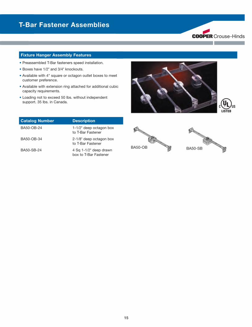
T-Bar Fastener Assemblies
14 15
• Preassembled T-Bar fasteners speed installation.
• Boxes have 1/2" and 3/4" knockouts.
• Available with 4" square or octagon outlet boxes to meet customer preference.
• Available with extension ring attached for additional cubic capacity requirements.
• Loading not to exceed 50 lbs. without independent support. 35 lbs. in Canada.
BA50-OB BA50-SB
Fixture Hanger Assembly Features
Catalog Number Description
BA50-OB-24 1-1/2" deep octagon box to T-Bar Fastener
BA50-OB-34 2-1/8" deep octagon box to T-Bar Fastener
BA50-SB-24 4 Sq 1-1/2" deep drawn box to T-Bar Fastener
CHEC_45234_PreFormance_Bro.indd 15 1/15/08 11:53:03 AM

1716
If you could not find an assembly in the previous pages to meet your specific
application or need to add connectors, devices, or other customizations, please
follow the steps in the next 3 pages to select an assembly that meets your needs.
Page 17 is an example of a custom assembly selection. After reviewing, use page
18 and 19 to make your own selection. Start by selecting the mounting method,
then select the appropriate box, mud ring and ground wire. You can then add
connectors and devices. If you need to specify other configurations including
various box/bracket configurations or MC whips, please specify on the 'Draw your
own request' page. After selecting the assembly that fits your needs, please fax a
copy of your selections or drawings to us at 315-477-5153 ATTN: PRE-formance
and we will evaluate and quote according to your requirements. Please email your
questions to: [email protected].
Custom Assemblies
CHEC_45234_PreFormance_Bro.indd 16 1/15/08 11:53:10 AM

1716
Example: 4 Square 2-1/8" Deep Box was selected and added to the Telescoping slider bracket
Example: Solid Ground wire was selected and added to the 4 Square 2-1/8" Deep Box and telescoping slider bracket
Example: 5/8" Raised mud ring was selected and added to the 4 Square 2-1/8" Deep Box with ground wire and telescoping slider bracket
Example: Duplex device was selected and added to the telescoping slider bracket, 4 square 2-1/8" deep box, ground wire, and mud ring
Example STEP 1: Select Mounting Method
Multiple Box Mounting Supports
■ 11-18" Stud Spacing (BB216TS)
■ 15-26" Stud Spacing (BB224TS)
Telescoping Slider Support
√
Example STEP 2: Select Box, Ground Wire and Mud Ring
Example STEP 3: (single box mount) and 4 (with multiple box mount supports) Select Devices and/or Connectors
Select Box Type
Select Mud Ring
C) 5/8" Raised Single Device (TP489) ■ ■ ■ ■√
Pos
ition
1 (S
ingl
e
box
mou
nt)
Pos
ition
2 (m
ultip
le
box
mou
nt, M
idd
le
Pos
on
16")
Pos
ition
3 (m
ultip
le
box
mou
nt) R
ight
P
os o
n 16
"
Pos
ition
4 (m
ultip
le
box
mou
nt) R
ight
P
os o
n 24
"
A) 4D - 4" Square 2-1/8" Deep (TP403) ■ ■ ■ ■√
Pos
ition
1 (S
ingl
e
box
mou
nt)
Pos
ition
2 (m
ultip
le
box
mou
nt, M
idd
le
Pos
on
16")
Pos
ition
3 (m
ultip
le
box
mou
nt) R
ight
P
os o
n 16
"
Pos
ition
4 (m
ultip
le
box
mou
nt) R
ight
P
os o
n 24
"
Select Ground Wire
B) Solid ■ ■ ■ ■√
Pos
ition
1 (S
ingl
e
box
mou
nt)
Pos
ition
2 (m
ultip
le
box
mou
nt, M
idd
le
Pos
on
16")
Pos
ition
3 (m
ultip
le
box
mou
nt) R
ight
P
os o
n 16
"
Pos
ition
4 (m
ultip
le
box
mou
nt) R
ight
P
os o
n 24
"
Pos
ition
1 (S
ingl
e
box
mou
nt)
Pos
ition
2 (m
ultip
le
box
mou
nt, M
idd
le
Pos
on
16")
Pos
ition
3 (m
ultip
le
box
mou
nt) R
ight
P
os o
n 16
"
Pos
ition
4 (m
ultip
le
box
mou
nt) R
ight
P
os o
n 24
"
15A 20A Select Devices (Wagos Included)
■ ■ Duplex Receptacle ■ ■ ■ ■ ■ ■ ■ ■√√
Example: Telescoping Slider Bracket was selected
Example of assembly after each selection
Custom Assemblies — Example Custom Assembly Selection
CHEC_45234_PreFormance_Bro.indd 17 1/15/08 11:53:24 AM

1819
Custom Assemblies — Selection Sheet Print a copy and fax your selection to 315-477-5153 ATTN: PRE-formance or email to [email protected]
If you could not find a selection in the previous pages, follow the steps and check the boxes next to each selection to assemble different configurations for your application.
Contact Name: __________________________________________________________
Customer Name: ________________________________________________________
Account Number: _______________________________________________________
Phone: _________________________________________________________
Fax/Email: ______________________________________________________
■ 16" Stud Spacing (BB816)
■ 16" Stud Spacing (BB716)
■ 24" Stud Spacing (BB824)
■ 24" Stud Spacing (BB724)
Please specify box distance from sides if other than standard 1st, 2nd, 3rd, or 4th
positions on open mounting brackets. _______________________________________
STEP 1: Select Mounting Method STEP 2: Select Box, Mud Ring, & Pre-Installed Ground Wire
Multiple Box Mounting Supports
Use Position 1 for single mount assemblies and for 1st position multiple mount assemblies. (Position 4 Only Available with 24" Stud Spacing)
Select Box Type
4D 4" Square 2-1/8" Deep (TP403) ■ ■ ■ ■
4 4" Square 1-1/2" Deep (TP404) ■ ■ ■ ■
5D (4-11/16") Square 2-1/8" Deep (TP521) ■ ■ ■ ■
5 (4-11/16") Square (TP523) ■ ■ ■ ■
4" Square 2 1/8" Deep 1" KO (TP436) ■ ■ ■ ■
4" Square Drawn 1 1/2" Deep 1/2" KO (TP410) ■ ■ ■ ■
4" Square Welded 2-1/8" Deep 3/4" KO (TP432) ■ ■ ■ ■
4-11/16" Square Drawn 2-1/8" Deep 1" KO (TP560) ■ ■ ■ ■
4-11/16" Square 1-1/2" Deep Square Drawn 1/2" 3/4" KO (TP548) ■ ■ ■ ■
4-11/16" Square Drawn 2 1/8" Deep 1" KO (TP560) ■ ■ ■ ■
4" Octagon Box 1-1/2" Deep 1/2" KO (TP274) ■ ■ ■ ■
4" Square Deep Open Back Box with Cvr (TPO67) ■ ■ ■ ■
4D 4" Square 2-1/8" Deep RED (TP403) ■ ■ ■ ■
Select Mud Ring Type
1/2" Raised Single device (TP484) ■ ■ ■ ■
5/8" Raised Single device (TP489) ■ ■ ■ ■
3/4" Raised Single device (TP486) ■ ■ ■ ■
1" Raised Single device (TP488) ■ ■ ■ ■
1-1/4" Raised Single device (TP490) ■ ■ ■ ■
1-1/2" Raised Single device (tile ring) (TP528) ■ ■ ■ ■
1/2" Raised Double device (TP498) ■ ■ ■ ■
5/8" Raised Double device (TP499) ■ ■ ■ ■
3/4" Raised Double device (TP500) ■ ■ ■ ■
1" Raised Double device (TP502) ■ ■ ■ ■
1-1/4" Raised Double device (TP501) ■ ■ ■ ■
1-1/2" Raised Double device (tile ring) (TP540) ■ ■ ■ ■
1/2" Raised Rnd (TP476) ■ ■ ■ ■
5/8" Raised Rnd (TP477) ■ ■ ■ ■
3/4" Raised Rnd (TP475) ■ ■ ■ ■
1" Raised Rnd (TP479) ■ ■ ■ ■
1-1/4" Raised Rnd (TP483) ■ ■ ■ ■
HORIZONTAL MOUNTING OPTION ■ ■ ■ ■
Select Ground Wire (Pre-Installed)
Solid ■ ■ ■ ■
Stranded (with fork) ■ ■ ■ ■
Devices (includes leads with Wagos attached) 1 2 3 4
Single Pole ■ 15A ■ 20A ■ ■ ■ ■ ■ ■ ■ ■
3-Way ■ 15A ■ 20A ■ ■ ■ ■ ■ ■ ■ ■
Single ■ 15A ■ 20A ■ ■ ■ ■ ■ ■ ■ ■
Duplex ■ 15A ■ 20A ■ ■ ■ ■ ■ ■ ■ ■
GFI ■ 15A ■ 20A ■ ■ ■ ■ ■ ■ ■ ■
Other Cooper Wiring Device Cat#___________ ■ ■ ■ ■ ■ ■ ■ ■
Ivory ■ ■ ■ ■ ■ ■ ■ ■
White ■ ■ ■ ■ ■ ■ ■ ■
Black ■ ■ ■ ■ ■ ■ ■ ■
Other Color/Grade_____________________ ■ ■ ■ ■ ■ ■ ■ ■
Protector Plate ■ ■ ■ ■
STEP 3: Select Commercial Device(If 1 device mud ring — select first box. If 2 device mud ring — 1st or 2nd box)
STEP 4: Select Fitting Type, Size and Position Steel EMT Connectors Trade Size 1 2 3 4
■ Set Screw ■ Insulated 1/2" 3/4" 1"
■ Compression ■ Non-Insulated ■ ■ ■
Space Saver EMT Connectors Trade Size
■ Set Screw 1/2" 3/4" 1"
■ Compression ■ ■ ■
Steel AC/MC (ACB & SSACB Type Fittings) Trade Size
■ Set Screw (ACB) 3/8" 1/2" 3/4" 1"
■ Space Saver ACB (SSACB) ■ ■ ■ ■
Quick-Lok AC/MC Connectors Trade Size
■ Quick-Lok Connector
1/2" Sgl 3/4" 1/2"
Duplex
■ ■ ■
Uni-Mount Box Support (For 4 Sq Box Only)
■ 1/2" Raised Single Gang Cover(TP30000)
■ 5/8" Raised Single Gang Cover(TP31000)
■ 3/4" Raised Single Gang Cover(TP32000)
■ 1/2" Raised Double Gang Cover(TP35000)
■ 5/8" Raised Double Gang Cover(TP36000)
■ 3/4" Raised Double Gang Cover(TP37000)
Floor Mount Slider Combo
■ 15" Height 11"-18" Stud Spcg (BFM154S16)
■ 15" Height 15"-26" Stud Spcg (BFM154S24)
■ 18" Height 11"-18" Stud Spcg (BFM184S16)
■ 18" Height 15"-26" Stud Spcg (BFM184S24)
Single Sided Box Support
■ 3-1/2" & 2-1/2" Stud Size (BB423)
■ 4", 3-1/2", & 2-1/2" Stud Size (BB44)
■ 6", 5-1/2", 3-1/2", & 2-1/2" Stud Size (BB46)
T Bar Fasteners
■ T Bar Fastener (BA50)
Floor Mount Support
■ 15" Height (BFM15)
■ 18" Height (BFM18)
■ 24" Height (BFM24)
Double Sided Box Support
■ 3-1/2" & 2-1/2" Stud Size (BB73)
■ 4", 3-1/2", & 2-1/2" Stud Size (BB74)
■ 6", 5-1/2", 3-1/2", & 2-1/2" Stud Size (BB76)
Telescoping Slider Support
■ 11-18" Stud Spacing (BB216TS)
■ 15-26" Stud Spacing (BB224TS)
Box 4Box 1 Box 2 Box 3
CHEC_45234_PreFormance_Bro.indd 18 1/15/08 11:53:33 AM
Custom Assemblies — Custom Assembly Selection Sheet — Draw your own requestPrint a copy and fax your selection to 315-477-5153 ATTN: PRE-formance or email to [email protected]
1819
If you need to further customize your assembly, use this page to draw your own configuration. Submit your own assembly configuration of boxes, brackets, devices, fittings, MC whips, etc. to us and we will evaluate and quote. Also if drawings or digital pictures are available, please forward via fax or email ([email protected]).Lead times will vary depending on complexity of design and availability of material.
Customer Name: __________________________________________________________
Contact Name: ___________________________________________________________
Phone: ___________________________________________________________________
Fax: _________________________________________________________________
Email: ________________________________________________________________
Account Number: ______________________________________________________
Comments: __________________________________________________________________________________________________________________________________
_____________________________________________________________________________________________________________________________________________
Draw Your Own Assembly
CHEC_45234_PreFormance_Bro.indd 19 1/15/08 11:53:43 AM
Your Authorized Cooper Crouse-Hinds Distributor is:
Printed in USA4901-0108
Cooper Industries, Ltd.600 Travis, Ste. 5800Houston, TX 77002-1001P: 713-209-8400www.cooperindustries.com
For more information:If further assistance is required, please contact an authorized Cooper Crouse-Hinds Distributor,
Sales Office or Customer Service Department:
www.crouse-hinds.comCooper Crouse-Hinds is a trademark of Cooper Industries, Inc.©2008 Cooper Industries, Inc.
U.S. (Global Headquarters):Cooper Crouse-HindsWolf & Seventh North StreetsSyracuse, NY 13221(866) 764-5454FAX: (315) 477-5179 FAX Orders Only: (866) [email protected]
Canada:Cooper Crouse-Hinds CanadaToll Free: 800-265-0502(905) 507-4187FAX: (866) 587-2850
Mexico:Cooper Crouse-Hinds, S.A. de C.V.52-555-804-4000FAX: [email protected]
Latin America/Caribbean:Cooper Crouse-Hinds, S.A. de C.V.52-555-804-4000 FAX: 52-555-804-4020
Singapore:Cooper Crouse-Hinds Pte. Ltd.65-6297-4849FAX: [email protected]
Australia:Cooper Electrical Australia61-2-8787-2777FAX: [email protected]
Europe (Germany):Cooper Crouse-Hinds GmbH49 (0) 6271 806-50049 (0) 6271 [email protected]
China:Cooper Crouse-Hinds Pte. Ltd.86-21-2899-3600FAX: [email protected]
India:Cooper Crouse-Hinds India91-22-6504-5150FAX: 91-22-2404-1811
Middle East (Dubai):Cooper Crouse-Hinds LLC971-4324-1578FAX: 971-4324-1640
Korea:Cooper Crouse-Hinds Korea82-2-3484-678382-2-3484-6778
CHEC_45234_PreFormance_Bro.indd 20 1/15/08 11:53:44 AM