pre-final geotechnical engineering report lower
TRANSCRIPT
Prepared by
Michael Baker Jr., Inc. Beaver, Pennsylvania
PRE-FINAL GEOTECHNICAL ENGINEERING REPORT
LOWER HILL REDEVELOPMENT PROJECT
PITTSBURGH, ALLEGHENY COUNTY, PENNSYLVANIA
Prepared for:
Sports and Exhibition Authority of
Pittsburgh and Allegheny County
December 2012 S.O. 127410

i
Sports and Exhibition Authority
Lower Hill Redevelopment Project
GEOTECHNICAL ENGINEERING REPORT FOR PRE-FINAL DESIGN
TABLE OF CONTENTS
1.0 INTRODUCTION .................................................................................................. 1
2.0 RECOMMENDATIONS ........................................................................................ 2
3.0 CONCLUSIONS..................................................................................................... 3
4.0 PHYSIOGRAPHIC SETTING ............................................................................... 4
5.0 ENVIRONMENTAL CONCERNS........................................................................ 4
6.0 ECONOMIC CONSIDERATIONS........................................................................ 5
7.0 SITE INVESTIGATION ........................................................................................ 5
8.0 SOIL, ROCK, AND HYDROLOGIC SETTING ................................................... 5
9.0 SUBSURFACE CONDITIONS AT ROADWAY LOCATIONS ......................... 8
10.0 RECOMMENDED FINAL DESIGN SUBSURFACE INVESTIGATION .......... 9
11.0 LIMITATIONS AND QUALIFICATIONS ......................................................... 10
12.0 REFERENCES ..................................................................................................... 11
FIGURES
Figure 1 - Project Location Map Figure 2 - Proposed Street Grid Figure 3 - Test Boring Location Plan Figure 4 - Stratigraphic Column
APPENDICES
APPENDIX A - Site Photographs APPENDIX B - Test Boring Logs APPENDIX C - Laboratory Testing APPENDIX D - Subsurface Profiles APPENDIX E - Draft Special Provisions

1
1.0 INTRODUCTION
This report presents preliminary design considerations for the project and was prepared in general accordance with Pennsylvania Department of Transportation (PennDOT) Publication 293, Sections 1.3.3, Geotechnical Engineering Manual, dated January, 1997 and Change No.1, December 1998 and associated addendums.
1.1 Location
The project site is located to the east of Pittsburgh’s Central Business District. The site is bounded by Crawford Street, Bedford Avenue, Washington Place and Centre Avenue. The location of the project is indicated on Figure 1 and the proposed street grid is shown on Figure 2.
1.2 Purpose/Scope
The purpose of this Pre-Final Geotechnical Engineering Report (GER) is to present the findings of the soils reconnaissance and geological engineering investigation, identify significant geotechnical features, and furnish interpretations of data collected in the vicinity of the proposed Lower Hill Redevelopment Project. Baker is authorized to perform this work by the Sports and Exhibition Authority.
1.3 Proposed Construction
Proposed construction for the site involves establishing a network of local streets shown in Figure 2 to permit development of the surrounding parcels. A discussion of the proposed construction and/or modification for each roadway baseline within the project area is presented in Section 9.0.

2
2.0 RECOMMENDATIONS The following sections present geotechnical recommendations for the project. It is assumed earthwork and pavements will be constructed in accordance with PennDOT Publication 408.
2.1 Embankments
Provide 2H:1V or flatter embankment slope ratios with construction benching to provide a firm, level base and adequate width for proper compaction.
Use on-site soils to construct embankments and subgrade. Clear and grub existing ground to remove topsoil and scarify the ground
surface prior to embankment construction. Remove or rubblize in place existing pavement prior to placement of any
embankment materials.
2.2 Excavations and Cut Slopes
Provide 2H:1V or flatter cut slope ratios in soil and rock. Remove or bury the existing concrete retaining wall from proposed Fullerton
Street to proposed Whitcomb Way. Saw cut and leave in-place the portion of retaining wall from Whitcomb Way to Bedford Avenue.
2.3 Pavement
A Pavement Design Report for the proposed local streets should be completed in a future design phase.
Design for a CBR of 5. Stabilize the subgrade by undercut and replacement as necessary.
Provide Special Rolling for all subgrade in accordance with the Standard Special Provision.
Provide for undercutting and backfill of weak subgrade areas as identified with Special Rolling.
Backfill undercuts in subgrade areas with embankment material meeting the requirements of suitable random material.
2.4 Structure Foundation
No proposed highway structures anticipated within the project limits.
2.5 Special Provisions
Special Provisions anticipated for the project are Special Rolling (Standard Special Provision) and Over excavation and Backfill of Subgrade (as identified through Special Rolling). See Appendix E for draft special provisions.

3
3.0 CONCLUSIONS
The following is a list of geotechnical conclusions for the proposed local streets to be constructed for the project.
3.1 Embankments
Embankments will be necessary to achieve the desired grade for the proposed roadways.
Embankment heights are not anticipated to exceed 20 feet. On-site soils are anticipated to meet the requirements specified in PennDOT
Publication 408, Section 206.2. A 2H:1V or flatter slope ratio for the embankment slopes may be used. Slope stability is not anticipated to be an issue with the shallow embankment
heights of 20 feet or less with 2H:1V or flatter slopes. Based on the environmental investigation, there is no limitation to the use of on-
site soils. Off-site waste should be in accordance with a Waste Management Plan that includes soil characterization.
3.2 Excavations and Cut Slopes
Most of the excavations will be shallow and completely in soil. Excavations are anticipated to be 24 feet or less in depth. Rock excavation is anticipated only for Fullerton Street. No groundwater is anticipated to be encountered. Cut slopes in soil and rock can be achieved with a 2H:1V or flatter slope ratio. Existing cut slopes within the project area were not identified to be susceptible to
rockfalls or landslides. Partial removal of an existing concrete retaining wall will be required during
grading for the proposed Wylie Avenue, Fullerton Street and Whitcomb Way. Since only small portions of the wall would remain between Fullerton Street and Whitcomb Way, completely remove or bury the retaining wall except for the portion of the wall between Whitcomb Way and Bedford Avenue.
3.3 Pavement
A Pavement Design Report for the proposed city streets will need completed in a future design phase, in accordance with PennDOT Publication 242.
Since subgrade will vary considerably throughout the project, provide subgrade treatment to improve subgrade strength to a CBR of 5.
Subgrade soils upon which pavement and embankments will be placed consist of existing fill and residual soils.
Existing fills may require undercutting as heavy construction traffic may identify weak subgrade areas during construction.

4
Subgrade should be proof rolled to identify weak subgrade areas requiring undercutting in accordance with the Standard Special Provision for Special Rolling.
Embankment material meeting Publication 408, Section 206 –Embankments can be used for backfill. Material requirements for use as backfill are included in the Special Provision - Over excavation and Backfill of Subgrade Areas.
3.4 Structure Foundation
No proposed structures anticipated within the project limits.
3.5 Special Provisions
Special Provisions anticipated for the project are: Subgrade Special Rolling to identify weak or otherwise unsuitable subgrade
areas. Over excavation and Backfill of weak and/or unsuitable subgrade areas
identified by Special Rolling. 4.0 PHYSIOGRAPHIC SETTING
The project area is located in the Pittsburgh Low Plateau Section of the Appalachian Plateau Physiographic Province. The topography consists of gently rolling hills and valleys of moderate relief. The project site has been extensively modified through cuts and fill placement during urban construction. The project area is located east of the junction of the Allegheny, Monongahela and Ohio Rivers.
5.0 ENVIRONMENTAL CONCERNS
The project site has been an urban area for over one hundred years and has contained numerous industrial and commercial operations that may have contaminated the soil and groundwater. The Phase I Environmental Site Assessment prepared by Michael Baker Jr. dated October 2012 indicates that most of the historic fill and weathered rock present at the site is classified as regulated fill and should be kept on-site during grading operations. Excess fill material to be transported off-site will need to be tested. The Phase I ESA concluded that it is probable that unidentified underground storage tanks are present at the project site and may be encountered during redevelopment. Consider providing provisions in the excavation contract to allow for quick identification and removal of underground storage tanks.

5
6.0 ECONOMIC CONSIDERATIONS
Potential coal or limestone seams that could be used as geologic resources, such as the Little Clarksburg coal, Wellersburg coal, Duquesne coal, Harlem coal, Brush Creek coal, and Upper Freeport coal, and Vanport limestone seam, are likely too thin and/or deep to be economically viable within the current project area. No oil or gas wells were located within the project area. Natural gas is expected to be present in the shale units deep beneath the site including the Marcellus and Utica formations. No data is available on the economic status of these formations within the project area. 7.0 SITE INVESTIGATION
7.1 Office Investigation
A number of literature sources were reviewed for the current project area including unpublished previous geotechnical investigation reports as well as published literature and mapping. Associated references are provided in Section 11.0.
7.2 Previous Subsurface Investigations
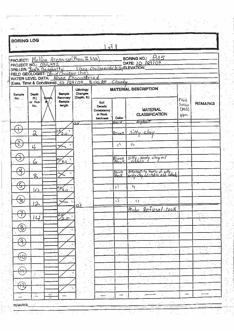
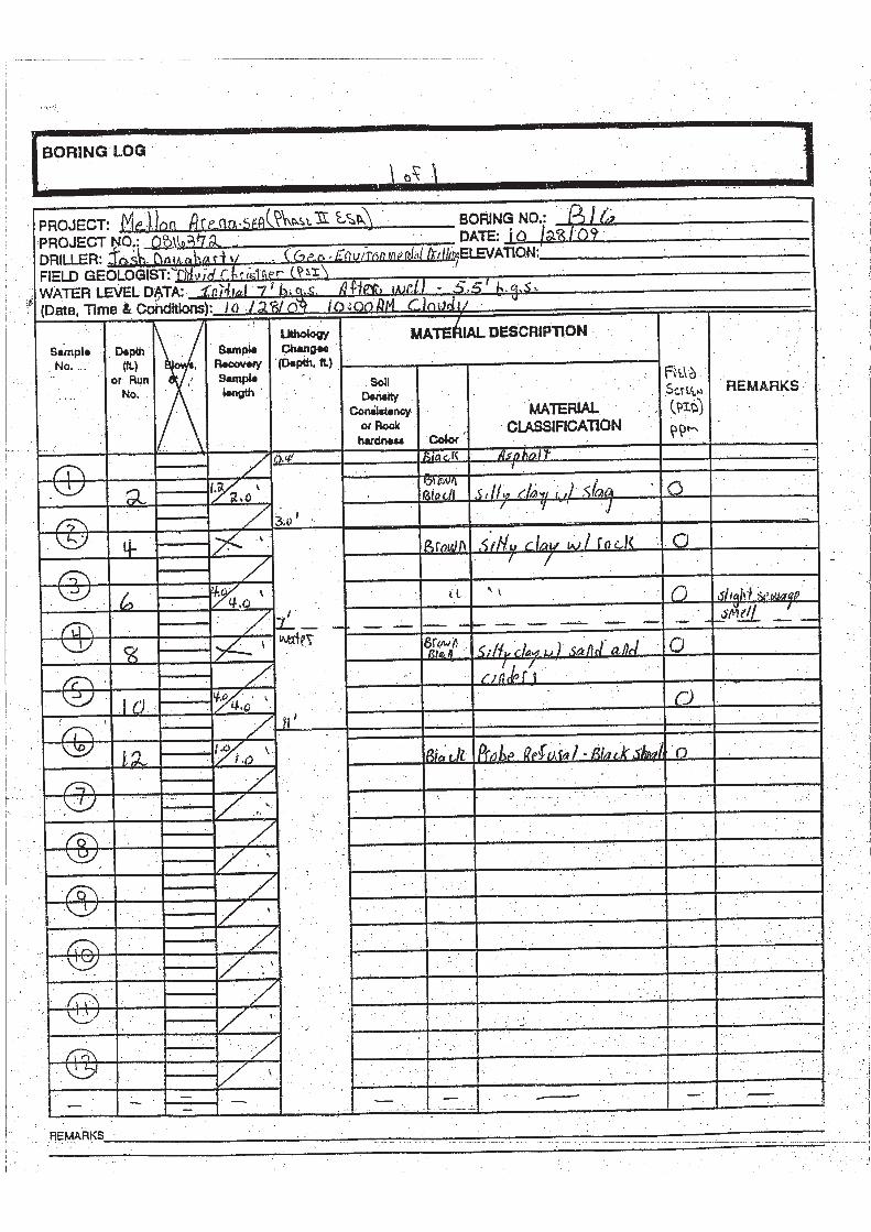
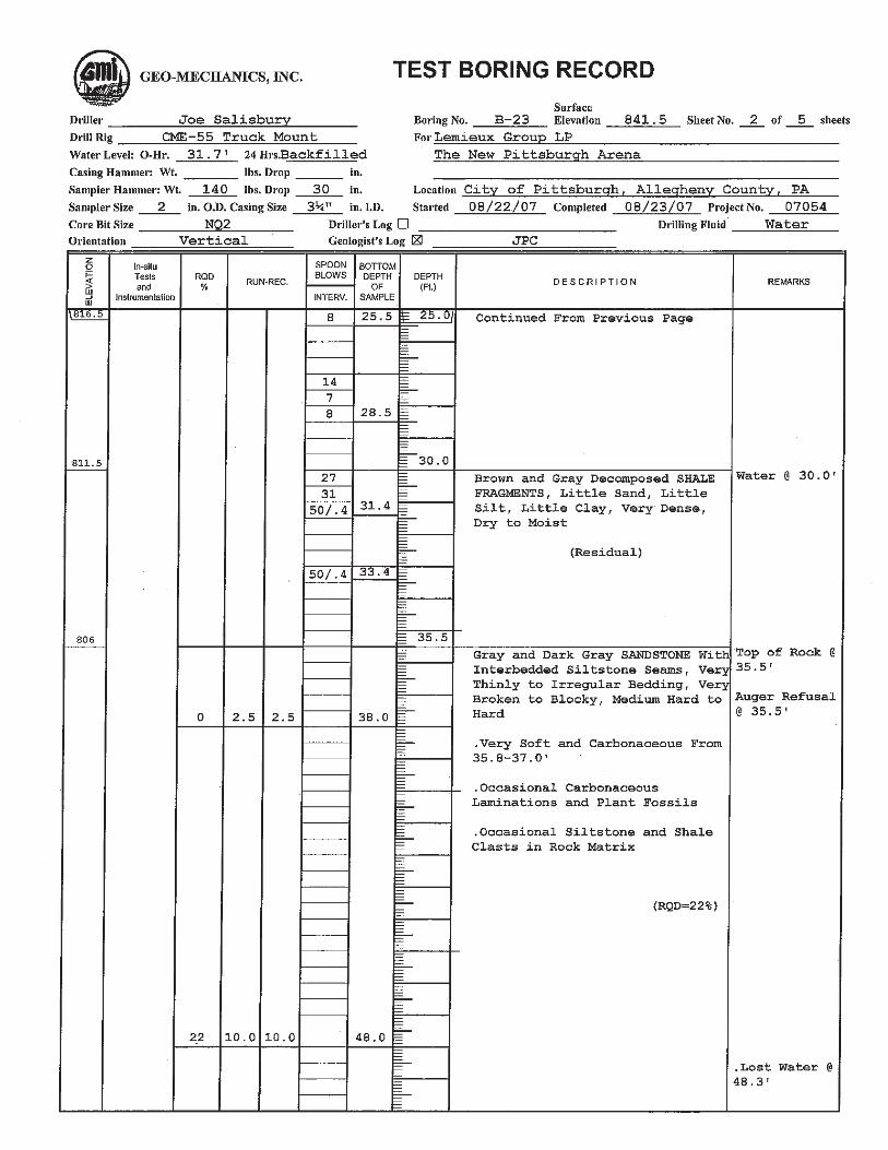
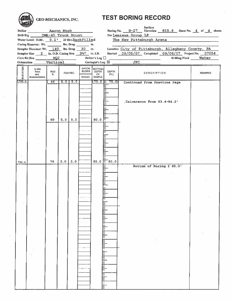
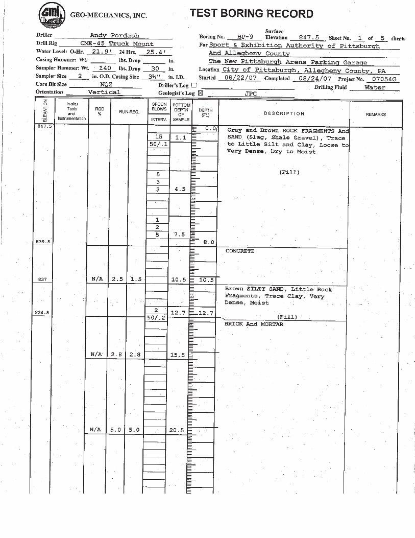
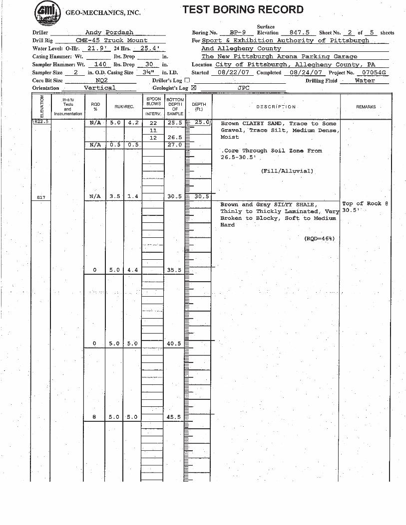
Data from several previous subsurface investigations was reviewed to determine the soil and rock characteristics of the site. Figure 3 presents locations of the test borings used for the site evaluation. See Appendix B for test boring logs and Appendix C for geotechnical laboratory test results. An environmental Phase II site assessment was conducted in 2010 by Professional Service Industries, Inc. for the area surrounding the Civic Arena. Twenty-one test borings were conducted to investigate the soils at the site. The results of these test borings, numbered B-1 to B-21, are discussed in Section 9.0. No soil engineering tests were conducted on these samples. Test borings were conducted for the Consol Energy Arena in 2008. Two test borings for the arena along Centre Avenue, numbered (GMI)B-23 and (GMI)B-27 and three test borings for the parking garage numbered BP-9, BP-11 and BP-12 are included in the evaluation of the project site as discussed in Section 9.0.
7.3 Site Reconnaissance
A field reconnaissance was conducted on October 1, 2012 by Baker personnel. Significant features observed during the field visit are presented below. Refer to Appendix A for site photographs. Since demolition of the Civic Arena, the project site is comprised of a series of parking areas terraced into the hillside between Washington Place and Crawford Street. As shown in Photographs 1 through 3, the upper parking area is separated from Crawford

6
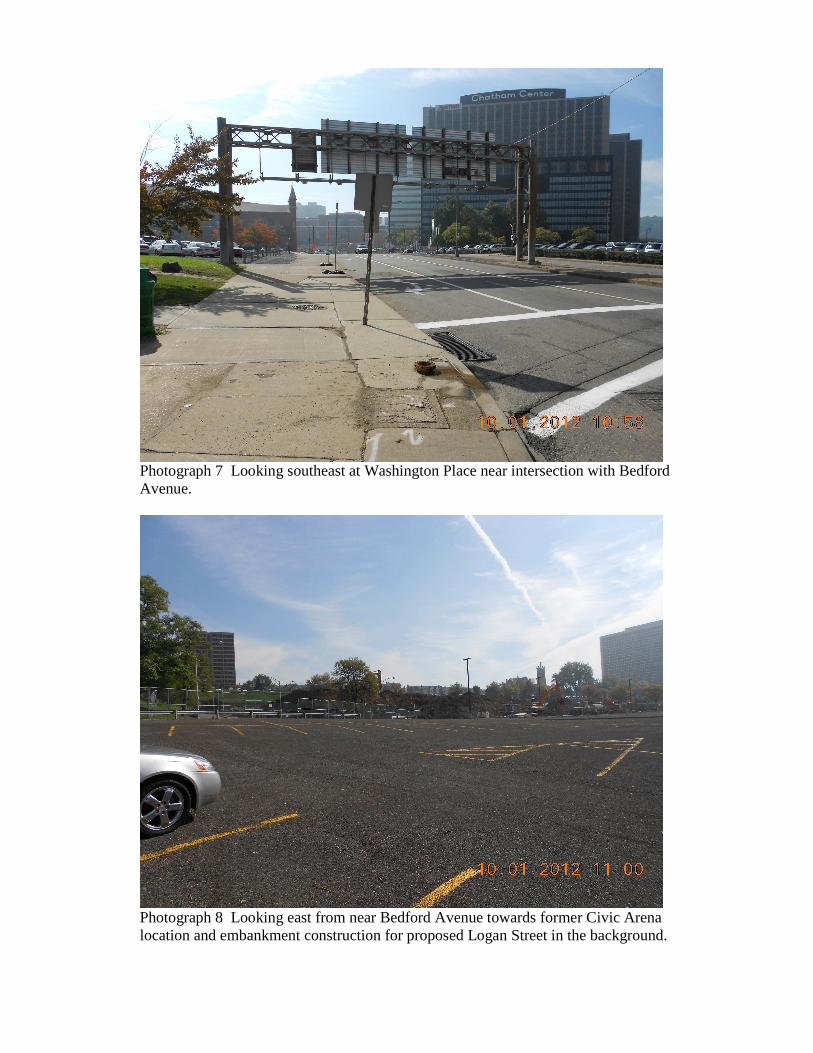
Street by a ten-foot high 2H:1V slope. The middle area is located ten feet below the upper area with a 2H:1V slope. A ten-foot high concrete cantilever retaining wall topped with a fifteen-foot high 2H:1V embankment supports the middle parking area above the lower parking area. The lower parking area is separated by Mario Lemieux Place. The lower parking area, which includes the former Civic Arena footprint, is covered with a combination of coarse aggregate and asphalt. At the time of the site reconnaissance, a large quantity of borrow was being placed in the vicinity of Mario Lemieux Place near the eastern side of the former arena. This material is reportedly being transported from the PNC Tower excavation in downtown Pittsburgh. A classification test and a proctor test for this material is presented in Appendix C. The newly constructed Consol Energy Arena and associated parking garage is located on Centre Avenue near the proposed intersection with Lemieux Place. The arena was built on the location of Saint Francis Hospital which apparently housed several basement levels beneath Centre Avenue grade. A small gabion wall, located near the intersection of Centre Avenue and Crawford Street, supports a corner of the upper parking lot as shown in Photograph 10. This wall will be removed during site grading. A sandstone outcrop was observed in a steep cut slope at the intersection of Webster Avenue and Crawford Street. A photograph of the location is shown in Photograph 11. 8.0 SOIL, ROCK, AND HYDROLOGIC SETTING
The soil, rock, and hydrologic conditions at the site were investigated through office research supplemented by field reconnaissance. A listing of published and unpublished literature and mapping reviewed for the current project area are presented under the references section.
8.1 Soil
The USDA Soil Survey of Allegheny County indicates that the predominant soil unit within the project area to be the Urban land-Culleoka complex, moderately sloping (UCD). Due to past development in the project area, the soils have been extensively modified through removal, burial, and cut/fill operations as part of the development of the city. Consequently, all of the soils in the current project area should be considered as some variety of the Urban Land soil type.
Pertinent information has been reported for the Urban land-Culleoka complex, moderately sloping (UCD). UCD is comprised of 65 percent Urban land (UB), 20 percent Culleoka soil (CuC and CuD), and 15 percent other soil types. UCD soil slopes are also typically between 8 and 25 percent. Urban land soils are considered to be comprised primarily of fill material that has been hauled in and placed over natural soil materials such that little to none of the original soil can be identified.

7
A soil classification test identified the soil as lean clay (CL) with a liquid limit of 26 and a plasticity index of 10. The AASHTO Classification was A-4(3).
8.2 Rock
The bedrock units underlying the site are members of the Pennsylvanian Period, Conemaugh Group. Distinct marker beds for the area are the Pittsburgh coal seam, representing the top of the Conemaugh Group, and the Ames limestone which is the base of the Conemaugh Group. Although the coal is absence from the site, the structure contour of the Pittsburgh coal is estimated at elevation 1060. The Ames limestone was encountered in the test borings for the Consol Energy Center at elevation 773. Exposed sandstone bedrock belonging to the Connellsville sandstone unit was observed just outside the project area at the corner of Webster Avenue and Crawford Street. The McMurray syncline is located approximately one mile east of the project site. The bedrock in the project area has a general dip direction towards the east at less than one percent. A generalized stratigraphic column is presented in Figure 4. Bedrock depth likely varies across the project area and typically includes a zone of weathered bedrock overlying more competent rock. The weathered bedrock may or may not be overlain by residuum and/or fill.
8.3 Geologic Hazards
None of the slopes within the project area are listed as susceptible to landsliding. Weak claystone bedrock associated with the Pittsburgh redbeds formation is located near the top of bedrock west of Washington Place. The Pittsburgh coal seam is not present on the project site. No mining has been reported in the Upper Freeport coal and other smaller coal seams beneath the site. No geologic strata within the project site are conducive towards formation of sinkholes and other karstic terrain features.
8.4 Hydrologic Setting
The Conemaugh Group contains water bearing members. The water bearing sandstone of the Conemaugh Group that may be encountered during subsurface investigations is the Connellsville sandstone. It is coarse grained, micaceous, and moderately permeable sandstone. It ranges in thickness from 20 to 75 feet thick. No declared wetlands are located within or adjacent to the project area. No other streams or rivers are anticipated to have any impact on the currently proposed project. No public or private water wells of any type were discovered during field or office investigations of the project area. The static groundwater level is relatively deep in this area. However, a significant number of perched aquifers likely exist within the soil zones. The bedrock hydrology in

8
the project area is typical of gently dipping sedimentary regimes which are determined primarily by the lithology and attitude of the regional bedrock. Groundwater is carried down dip in fractures and joint sets in the more resistant rock units. The primary water bearing rock units within the site are limestones, sandstones, shales, and coals.
9.0 SUBSURFACE CONDITIONS AT ROADWAY LOCATIONS
The following discussion presents a summary of the subsurface conditions encountered at the project site. Test boring logs are presented in Appendix B. A plan indicating the location of the test borings within the project site is presented in Figure 3. Subsurface profiles are shown in Appendix D.
9.1 Wylie Avenue
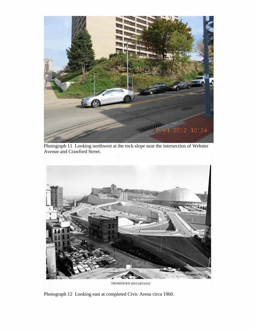
Proposed Wylie Avenue will extend from the intersection with Washington Place at Station 40+00 to the intersection with Crawford Street at Station 54+20. From Station 40+00 to 41+75, a shallow cut with a maximum depth of two feet will be required. Test Boring B-13 encountered eight feet of silty clay overlying six feet of sandy clay with sandstone fragments on top of bedrock. A shallow embankment with a maximum height of eleven feet is required from Station 41+75 to the intersection with Logan Street at Station 48+60. Since this area is the location of the former Civic Arena, the subsurface conditions are expected to consist of silty clay and demolition debris overlying a highly variable bedrock surface due to the numerous excavations for construction of the arena as shown in Photographs 13 to 17. From the intersection with Logan Street at Station 48+60, the Wylie Avenue profile will require a cut to Station 52+60. The cut will have a maximum height of fifteen feet and intercept the existing ten-foot high concrete retaining wall supporting the middle parking area at Station 50+40. Test Borings B-6 and B-4 encountered eight feet of silty clay overlying bedrock. Test Boring B-4 had an overlying nine-foot thick layer of silty clay fill comprising the parking lot embankment above the retaining wall. Bedrock may be encountered in this cut. From Station 52+60 to the intersection with Crawford Street at Station 54+20, a shallow fill with a maximum depth of five feet will be required. Test Boring B-3 encountered nine feet of silty clay fill overlying four feet of silty clay with shale fragments on bedrock.
9.2 Fullerton Street
Proposed Fullerton Street will extend from the intersection with Logan Street at Station 200+00 to the intersection of existing Centre Avenue at Station 207+25. The roadway alignment will have a ninety-degree bend at Station 202+60. Fullerton Avenue will be entirely in cut with a maximum depth of twenty-four feet. Near Station 201+75, the cut will remove an existing concrete retaining wall supporting the middle\upper parking area.

9
Test Boring B-20 encountered approximately seven feet of silty clay overlying bedrock and Test Boring B-5 sampled eight feet of silty clay fill overlying six feet of silty clay with shale fragments. The proposed cut is expected to require approximately ten feet of rock excavation. 9.3 Lemieux Place The proposed relocated Lemieux Place roadway will extend from the intersection with Bedford Avenue at Station 80+00 to the intersection with Centre Avenue at Station 89+15. The roadway will be supported by a new embankment with a maximum depth of eight feet at the intersection of proposed Wylie Avenue at Station 85+25. Test Borings B-10 at Station 81+50 sampled nine feet of silty clay fill overlying two feet of silty clay with shale fragments on bedrock. Test Boring B-18 near Centre Avenue at Station 886+50 encountered twenty-four feet of silty clay with rock fragments. This soil profile is similar to the deep soil zones found during the Consol Energy Arena exploration, Test Borings GMI B-23 and GMI B-27, which are believed to be associated with the former Saint Frances Hospital which was demolished for the Arena construction.
9.4 Logan Street
Proposed Logan Street will extend from the intersection of Bedford Avenue at Station 90+00 to the intersection with Centre Avenue at Station 101+10. From Station 90+00 to Station 94+10, the proposed roadway will be placed on embankment with a maximum depth of twenty feet near Station 91+00. Test Boring B-8 encountered twelve feet of silty clay with rock fragments over bedrock and Test Boring B-9 sampled five feet of silty clay with shale fragments overlying bedrock. From Station 94+10 to 101+10, the Logan Street alignment will be constructed on a shallow embankment with a maximum height of two feet. Test Boring B-19 encountered eleven feet of silty clay with rock fragments.
9.5 Whitcomb Way
Proposed Whitcomb Way will extend from the intersection with proposed Logan Street at Station 300+00 to Station 303+40. The proposed roadway will be mainly in cut and will require the excavation of the existing ten-foot high concrete retaining wall near Station 301+70. Test Boring B-7 encountered eleven feet of silty clay fill overlying two feet of sandy clay with sandstone fragments and bedrock. 10.0 RECOMMENDED FINAL DESIGN SUBSURFACE INVESTIGATION
The previous subsurface investigations described in Section 7.0 of this report will be adequate to address roadway geotechnical issues for Final Design. Pavement Design will be required in Final Design.

10
11.0 LIMITATIONS AND QUALIFICATIONS
The opinions expressed in this report are based on the results of field explorations made by others and engineering judgment. The geotechnical engineer should review the PS&E submission for this project to verify the submission is in accordance with this geotechnical engineering report. The opinions expressed in this report are based on the results of geotechnical test drilling and laboratory testing programs conducted by others. Baker assumes that this information is accurate. If deviations from the noted conditions are encountered during construction, they should be brought to the attention of the geotechnical engineer. The professional services have been performed, findings obtained, and recommendations prepared in accordance with generally accepted geotechnical engineering principles and practices. No other warranty, expressed or implied, is made as to the professional advice included in this report. Michael Baker Jr., Inc. is not responsible for the conclusions, opinions, and recommendations made by others based upon the data included herein.

11
12.0 REFERENCES
Lower Hill Preliminary Land Development Plan. Urban Design Associates, et al, 2012. Phase I Environmental Site Assessment Report, Lower Hill Redevelopment Project. Michael Baker Jr., Inc., October 2012. Phase II Environmental Site Assessment Report. Professional Services Industries, Inc., March 1, 2010. Final Geotechnical Engineering Investigation Report, The New Pittsburgh Arena. GeoMechanics, Inc., October 2008. Geotechnical Engineering Investigation Report, The New Pittsburgh Arena Parking Garage. GeoMechanics, Inc., December 2008. Dodge, Clifford H., 1985, Coal Resources of Allegheny County, Pennsylvania - Part 1, Coal Crop Lines, Mined-Out Areas, and Structure Contours. Pennsylvania Department of Environmental Resources, Bureau of Topographic and Geologic Survey, Mineral Resource Report 89, Part 1. Lytle, W.S. and L. Balogh, 1975, Greater Pittsburgh Region Oil and Gas Fields Map 44. Department of Environmental Resources and Topographic and Geologic Survey. National Wetlands Inventory Map: Pittsburgh West Quadrangle. National Wetlands Inventory, Fish and Wildlife Service, U.S. Department of the Interior. Newbury, R.L., Belz, D.J., and R.G. Grubb, 1981, Soil Survey of Allegheny County, Pennsylvania. U.S. Department of Agriculture - Soil Conservation Service, Pennsylvania State University - College of Agriculture, and Pennsylvania Department of Environmental Resources - State Conservation Commission. Pittsburgh East 7.5 Minute Quadrangle Map. United States Department of the Interior, Geological Survey and State of Pennsylvania, Department of Internal Affairs, Topographic and Geologic Survey. 1997 and 2010. Wagner, W.R., Craft, J.L., Heyman, L., and J.A. Harper, 1975, Greater Pittsburgh Region Geologic Map and Cross Sections (Map 42). Bureau of Topographic and Geologic Survey, Commonwealth of Pennsylvania and United States Department of the Interior Geological Survey. Wagner, W.R., Heyman, L., Craft, J.L., Edmunds, W.E., and J.A. Harper, 1975, Greater Pittsburgh Region Structure Contour Map (Map 43). Bureau of Topographic and Geologic Survey, Commonwealth of Pennsylvania and United States Department of the Interior Geological Survey.

FIGURES

Figure 1 Project Location Map
Lower Hill Redevelopment Project Pittsburgh, Allegheny County, Pennsylvania
Scale: na Elevation Datum: NAVD 1988 Source: 7.5-Minute Quadrangle, Pittsburgh East, PA, U.S. Geological Survey, U.S. Department of the Interior, 1997.
N
Project Location

Figure 2 Lower Hill Redevelopment Project
Pittsburgh, Allegheny County, Pennsylvania Source: Lower Hill Redevelopment Plan, Urban Design Associates, September 2012.

B-3
B-2
B-1
B-4
B-5
B-6
B-7
B-20B-19
B-9
B-8
B-10
B-11
B-21
B-12
B-13
B-16
B-17
B-18
B-15
B-3A
GMI
B-23
GMI
B-27
GMI
BP-11
GMI
BP-9
GMI
BP-12
Figure 3
Test Boring Plan

Figure 4 Stratigraphic Column
Lower Hill Rehabilitation Project Pittsburgh, Pennsylvania
Source: Mining and Physiography, Allegheny County, A.C. Ackenheil & Associates, Inc., 1968
Elevation 1060
Elevation 773

Appendix A
Site Photographs

Photograph 1 Looking southeast at upper parking area from Bedford Avenue towards Centre Avenue.
Photograph 2 Looking southeast at middle parking area from Bedford Avenue towards Centre Avenue.

Photograph 3 Looking southeast at lower parking area from Bedford Avenue towards Centre Avenue. Note concrete retaining wall separating the parking levels.
Photograph 4 Looking south at the middle and lower parking levels from Bedford Avenue. Civic Arena has been demolished.

Photograph 5 Looking southeast at the lower parking area. Excavated material is being placed on former Mario Lemieux Place near proposed embankment for Logan Street.
Photograph 6 Looking northeast at Bedford Avenue near the intersection of Bedford Avenue and former Mario Lemieux Place.
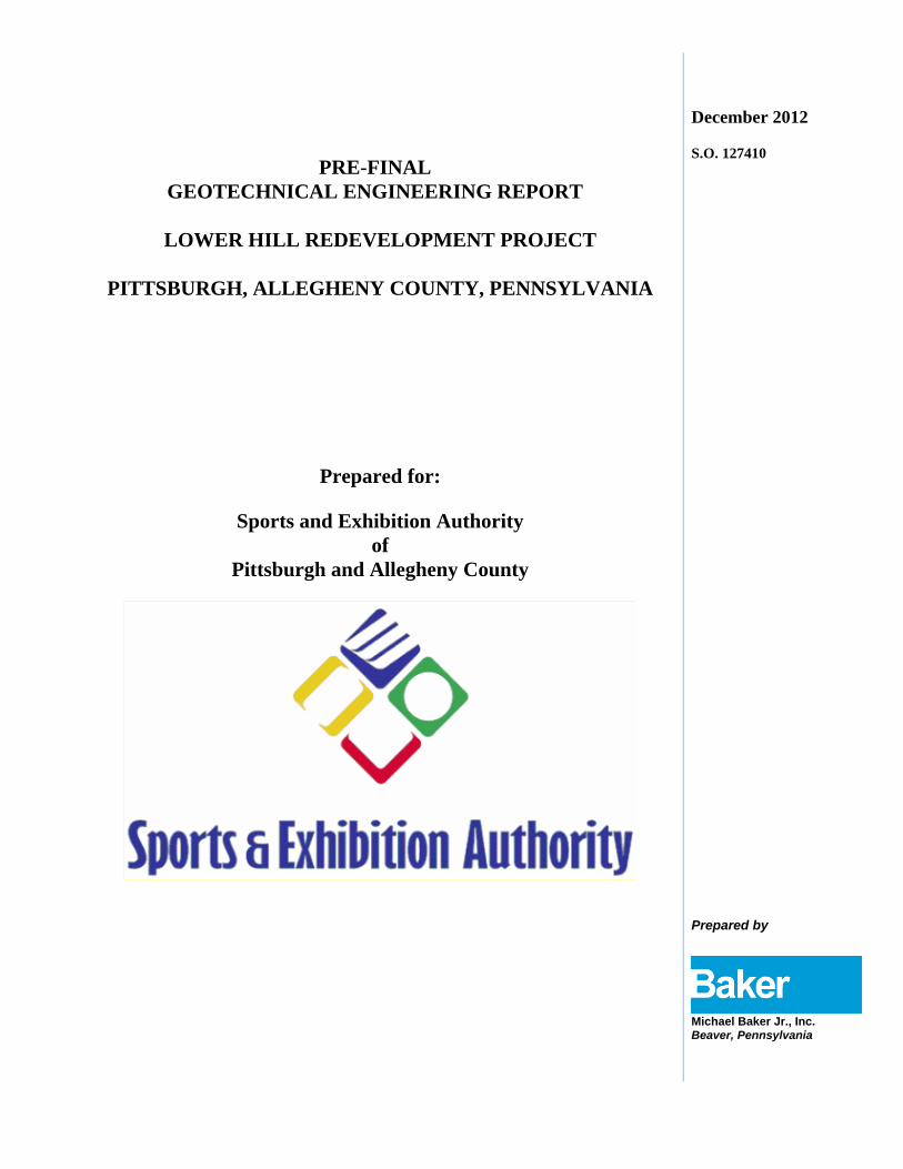
Photograph 7 Looking southeast at Washington Place near intersection with Bedford Avenue.
Photograph 8 Looking east from near Bedford Avenue towards former Civic Arena location and embankment construction for proposed Logan Street in the background.

Photograph 9 Looking southeast towards embankment construction for proposed Logan Street.
Photograph 10 Looking north from Centre Avenue towards a gabion wall supporting the upper parking area near the intersection with Crawford Street.
Photograph 11 Looking northwest at the rock slope near the intersection of Webster Avenue and Crawford Street.
Photograph 12 Looking east at completed Civic Arena circa 1960.
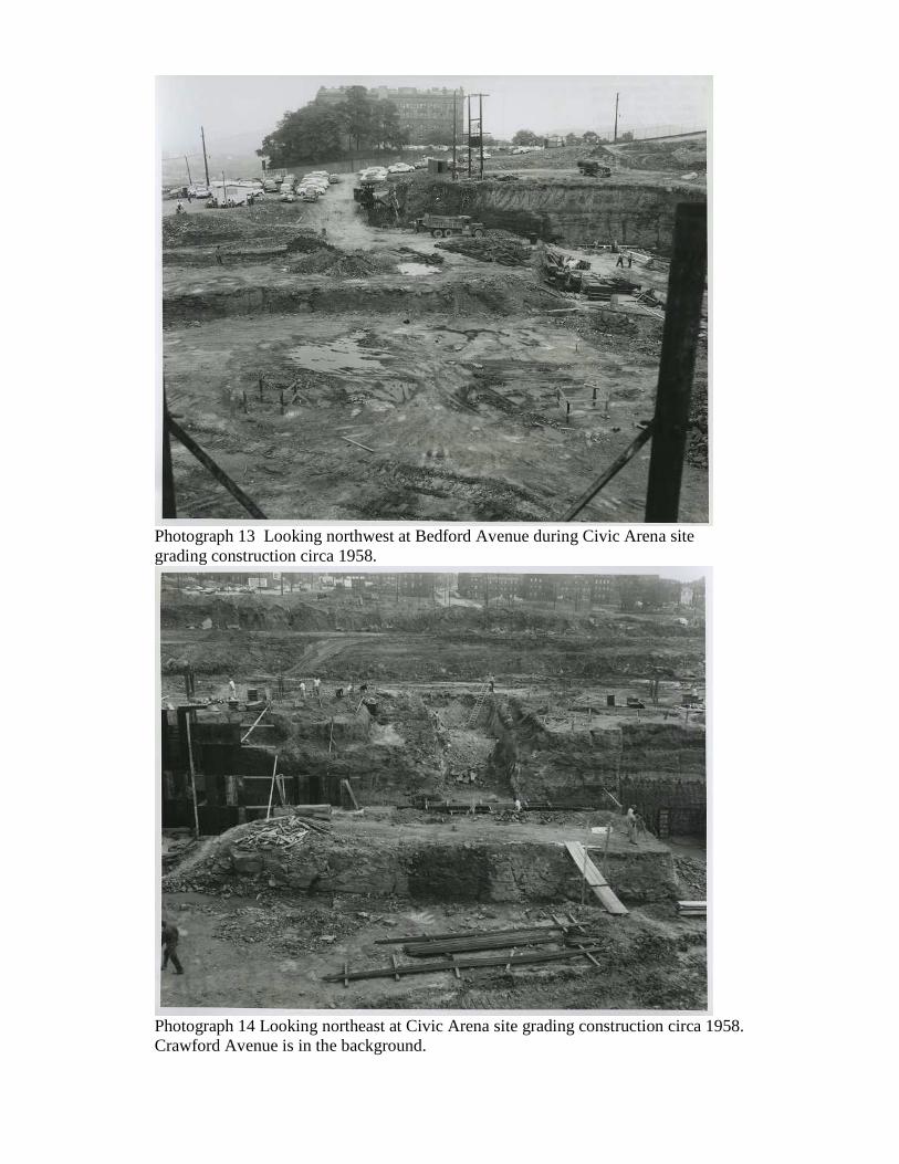
Photograph 13 Looking northwest at Bedford Avenue during Civic Arena site grading construction circa 1958.
Photograph 14 Looking northeast at Civic Arena site grading construction circa 1958. Crawford Avenue is in the background.

Photograph15 Looking northeast at Civic Arena site grading construction circa 1958. Crawford Avenue is in the background.
Photograph 16 Looking southwest at foundation excavations for the Civic Arena circa 1958.

Photograph 17 Looking southwest at foundation excavations for the Civic Arena circa 1958.

Appendix B
Test Boring Logs


Appendix C
Laboratory Testing


Appendix D
Subsurface Profiles

B-13
B-6
B-4 B-3
Fill
Fill
14.0
8.0
15.5
13.0
Fill

B-10
B-18
GMI
B-23
Building
Rubble
Fill
Fill
11.0
24.0

B-8
B-19BP-9
Building
Rubble
Shale
Bedrock
12.0
10.5

B-20
B-5
B-7B-8
B-4
GMI
BP-12
Offset
Building
Rubble
Sandstone
Bedrock
Shale
Bedrock
Fill
13.5
6.5
13.0
15.5
12.0
Fill
Fill
WHITCOMB WAY

Appendix E
Draft Special Provisions
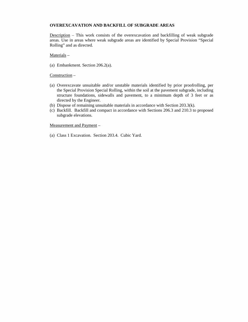
OVEREXCAVATION AND BACKFILL OF SUBGRADE AREAS
Description – This work consists of the overexcavation and backfilling of weak subgrade areas. Use in areas where weak subgrade areas are identified by Special Provision “Special Rolling” and as directed.
Materials –
(a) Embankment. Section 206.2(a). Construction –
(a) Overexcavate unsuitable and/or unstable materials identified by prior proofrolling, per the Special Provision Special Rolling, within the soil at the pavement subgrade, including structure foundations, sidewalls and pavement, to a minimum depth of 3 feet or as directed by the Engineer.
(b) Dispose of remaining unsuitable materials in accordance with Section 203.3(k). (c) Backfill. Backfill and compact in accordance with Sections 206.3 and 210.3 to proposed
subgrade elevations. Measurement and Payment –
(a) Class 1 Excavation. Section 203.4. Cubic Yard.

SPECIAL ROLLING
Description - This work is the special rolling of areas as indicated or as directed by the Engineer.
Material –
(a) Use acceptable pneumatic-tired equipment for special rolling, capable of varying the load from 267 kN (30 tons) to 445 kN (50 tons). Use a roller constructed to transmit the load through four wheels, equally spaced over the roller width, mounted on two (2) or four (4) axles in line, permitting oscillation of the individual wheels or pairs of wheels. Use a roller with tires capable of operating at inflation pressures ranging from 0.62 MPa (90 pounds per square inch) to 1.03 Mpa (150 pounds per square inch). Provide charts or tabulations showing the contact areas and contact pressures for the full range of tire inflation pressures and loadings for the particular tires furnished.
Construction –
(a) Adjust the roller load and tire pressures for contact pressures to approximately the maximum supporting value of the layer being rolled. When the special rolling of any layer shows an area to be unstable or nonuniform, satisfactorily stabilize the area by providing additional compaction on these areas or by removing the unsuitable material, replacing it with suitable material, and recompacting.
(b) Operate the roller in a systematic manner so the number of passes can be readily determined and recorded. Normally, operate the roller at a speed of not less than 4.0 km/h (2-1/2 miles per hour).
(c) Perform special rolling only in the presence of the Inspector-in-Charge who will approve
or disapprove the stability of the embankment and recommend corrective measures.
Measurement and Payment – Hour.
No measurement and payment will be made for idle equipment time because of repairs, servicing, loading or unloading ballast, increasing or decreasing tire pressure, bad weather, or for any other similar reason.