pre feasibility report · equipment removes the solids of different sizes which get mixed with the...
TRANSCRIPT

PRE FEASIBILITY REPORT

Page | 1
Introduction:
India’s demand for petroleum products are growing at a rapid rate, current consumption is
around the capacity of 400MT equivalent. This will be 900MT (approx.) by 2030. As per ONGC
perspective plan 2030, it aspires to increase its share in India’s hydrocarbon consumption from the
current 22% to 27% by 2030 and targeting growth rate of 4-5%. Whereas as present growth rate 1-
2% in last decade. For achieving this growth ONGC will need to maintain focus on its core exploration
and production (E&P) business. We have to drill more exploration and development wells to
increase the production which is significant importance to balance the hydrocarbon demand of the
nation. Till date, 32 fields have been discovered in Cauvery sedimentary Basin. Bhuvanagiri and
Periyakudi Fields are the two major gas fields of Cauvery Asset in terms of huge reserves locked up
for exploitation. As per MoPNG & DGH guidelines, ONGC management has been firmed up for fast
track exploitation of these tight gas reservoirs under 10% import reduction of India’s crude oil.
Bhuvanagiri Field:
The field is located in Ariyalur – Pondicherry Sub-basin of Cauvery Basin and is about 10 KM
North-West of Chidambaram town. It was discovered in the year 1987 by the discovery well, BVG#2
has established commercial hydrocarbon in October 1987 from Bhuvanagiri Formation. Till date,
total of 12 exploratory wells have been drilled in the field, out of which five are completed as gas
producers. The Bhuvanagiri reservoir is encountered in the depth range of 3300-3800m, dominantly
with thin alternations of shale and sandstone. The Petro physical characteristics indicate that the
reservoir is extremely tight with low permeability. The clay matrix is mainly responsible for drastic
reduction in permeability and productivity. As it is a low permeability tight reservoir the convention
drilling and completion methods are not sufficient for effective recovery of oil & gas. The field could
not be exploited to the desired level due to complexities in subsurface reservoir and low
permeability, difficulties in drilling with water base mud, completion, testing and effective
stimulation. Although it has been discovered three decade earlier and its actual potential in terms
of reserves and production was not fully understood.
M/s Blade Energy Partners, consultant hired to study the Bhuvanagiri field in order to
develop a comprehensive strategy for exploitation of huge gas reserves established in the field. The
consultant was submitted detailed Field Development Plan (FDP) report. M/s. Blade Energy came

Page | 2
out with recommendations for implementation of Bhuvanagiri FDP in two phases, Phase-I with 4 Hz
wells and Phase-II with 13 Hz wells. A total of 17 Hz wells have been suggested for development.
Four wells have been planned to put on production during phase-I of development. Drilling of
remaining 13 wells and expansion of surface facility like gathering system with enhanced gas
handling capacity of up to 100MMSCFD has been proposed in the second phase of the development.
Due to the tight nature of the reservoir, blade energy has suggested drilling the proposed
wells by using LTSOBM (Low toxicity oil based mud) for trouble free drilling and multi stage HF
(Hydro Fracturing) for enhanced recovery of gas.
Periyakudi Field:
The field was discovered in May-2011, belongs to Nagapattinam Sub-basin of Cauvery Basin.
Field is located at 20KM North-West of Tiruvarur town, near Kovilkalappal and Adichapuram fields.
Huge pile of hydrocarbon potential (Gas) in the depth range of 4180 – 4820m with an average pay
thickness of 640m is present in Periyakudi field. 3 exploratory wells have been drilled in Periyakudi
field and presence of commercial hydrocarbon was proved though testing. The major chunk of yet
to find hydrocarbon potential in Cauvery Basin remains in this type of syn-rift sequence particularly
in the Nagapattinam sub-basin. The age of the prospect is Late Jurassic/Early Cretaceous. Reservoir
pressure is 12,666psi and temperature is 325°F hence the field falls in High Pressure High
Temperature (HP-HT) category. The permeability of the sand is very poor about 0.01mD and
porosity is 9-10%. Though the field has huge pay thickness of 640m, the productivity is very low due
to poor reservoir facies development. Exploitation of hydrocarbon from this tight reservoir is really
a challenge. In the field development plan, it was recommended drilling the wells with LTSOBM (Low
toxicity oil based mud) to avoiding drilling complications and HF for better recovery from tight
reservoir.
1. Description of Mining Lease area:
Project region ML Block name Block area Sq.km
Remarks
Tamil Nadu State
Bhuvanagiri ML & PML area of Bhuvanagiri
14.0 & 77.8
Cuddalore District
Periyakudi ML area 396 Tiruvarur District

Page | 3
2. Details of proposed Drilling Activity:
The locations are proposed to be drilled by Hired Electrical Type-III rigs which have capacity
to drill to depth of 5000m. The technical details of the proposed drilling activity are given below.
Well Depth Approx 3800m -4500 m
No of wells to be drilled 27
Duration of drilling 130-150 Days
Aprox. Qty. of drilling fluid per wells
600m3
Aprox Qty. of cuttings, Cu.M per well
550-615m3
Aprox Qty. of drilling, Waste water Cu.M per well
800-1000 m3
Development plan in case of strike
Already existing field, FDP submitted for 17 wells in Bhuvanagiri, 10 wells planned in Periyakudi Field
HC reserve (initial in place) IGIP-47021.437 MMSCM & IOIP- 0.042MMt (Bhuvanagiri). IGIP-26507.10 MMSCM & IOIP-20.93MMt (Periyakudi)
Formation Pressure Hydrostatic + 40-60%
Testing flaring, duration 2 to 3 days (oil is confined to the oil pit)
2.1 Details of drilling rig proposed to be deployed
Type of rig Electrical Rig (Type-III)
Drilling mud composition Water Based drilling Fluid up to 3200m. LTSOBM Usage in final phase (from 3200-5000m).
Power generator type & nos. AC-SCR Type (04Nos) for Type-III rig
Diesel consumption 6m3/day
Qty. of fresh water requirement & source 25m3/day. Bore well/ Transported from nearby source through contractor
Manpower on rig 35 per shift of 12 hrs. Two shifts per day.
Material requirement & Mobilization From ONGC base in Karaikal
Details of solid handling system on rig Shale Shakers- 1200 GPM capacity, De-sander- 1200 GPM Capacity, Desilter-1200 GPM Capacity
Details of Sewage treatment facility, if any Not applicable.
Waste pit availability & Size 90x13-25x1.5m
Oil Pit availability & Size 60’x20’x4’-1No.

Page | 4
2.2 Drilling Operations
1. Drilling operations can be carried out using an onshore rig. Drilling unit for drilling of oil & gas
wells consist of a derrick at the top of which is mounted a crown block and a hoisting block with a
hook. From the swivel is suspended a Kelly stem passes through a square of hexagonal Kelly bush
which fits into the rotary table. The rotary table receives the power to drive it from and electric
motor. The electric motor rotates the rotary table which passes through the Kelly bush and the
rotations are transmitted to the bit as the drilling progresses, the drill pope singles of length around
9 meters are added to continue the drilling process. At the end of the bit life, the drill pipes are
pulled out in stands and stacked on the derrick platform. A stand normally has 3 single drill pipes.
After changing the bit, the drill string is run back into the hole and further drilling is continued. This
process continues till the target depth is reached.
2. During the course of drilling, cuttings are generated due to crushing action of the bit. The mud
from the pump discharge through the rotary hose connected to stationery part of the swivel, the
drill string and bit nozzles. The mud coming out of the bit nozzles pushes the cuttings up hole and
transports them to the surface through the annular space between the drill string and the hole. The
mud not only carries away crushed rock from the bottom of the hole but it also cools the bit as it
gets heated due to friction with formation while rotating. The mud also helps in balancing
subsurface formation pressures and by forming a cake on the walls of the well diminishes the
possibility of crumbling or caving of the well bore.
3. At the surface, the mud coming out from well along with the cuttings falls in a trough, passes
through the solids control equipment i.e. shale shaker, de-sander/desilter and mud cleaner. This
equipment removes the solids of different sizes which get mixed with the mud during the course of
drilling. The cleaned mud flows back to the suction tanks to be pumped again into the well. The
drilling mud/fluid circulation is thus a continuous cyclic operation.
4. The most suitable clay for mud preparation is which is capable of forming highly dispersed
colloidal solutions. Various other chemicals are also used in mud preparation as per requirements
dictated by the temperature/pressure conditions of the wells. The mud is continuously tested for
its density, viscosity, yield point, water loss, pH value etc., to ensure that the drilling operations can
be sustained without any down hole complications.

Page | 5
5. Drilling is temporary activity in a location spanning over 90-150 days for one well. The rigs are
self-contained for all routine jobs. Once the drilling operations are completed and if sufficient
indications of hydrocarbons are noticed while drilling, the well is tested by perforation in the
production casing. If the well is found to be a successful hydrocarbon bearing structure, it is seated
off for future development, if any.
2.3 General Requirements of Drilling
Development drilling program requires the following common facilities:
1. Drilling of wells requires specially formulated mud which basically comprises inert earth materials
like barite in water with several additives to give mud weight, fluidity and filter cake characteristics
while drilling. The drilling mud have several functions like lubrication and cooling of the drill bit,
balancing subsurface formation, bringing out the drill cuttings from the well bore, thixotropic
property to hold cuttings during non-operations, formation of thin cake to prevent liquid loss along
well bore etc. Several additives are mixed into the mud system to give the required properties.
2. Water based mud will be used to the possible extent in drilling but use of synthetic based mud
may require due to complexities associated with the geological formations and associated hole
stability problems. The constituents of water based mud (WBM) are given in Table-2.
Table-2: Ingredients of Water Based Drilling Fluid.
Sl. No Name of The Raw Material
1 Limestone
2 Bentonite
3 Caustic Soda
4 Soda ash
5 XC Polymer
6 PHPA
7 PAC-RG
8 PAC-LV
9 PGS
10 Drilling Detergent
11 Sodium Chloride
12 Potassium Chloride
(All Chemicals are environment friendly)
3. Contractual mud service is planned for Bhuvanagiri & Periyakudi wells right from spudding to
completion of the wells. Contractor shall build, operate a mud plant of capacity 10000 bbls to

Page | 6
store/process base oil, LTSOBM, Water base mud and brine during the contract period and after the
contract period handover the mud plant in running condition to ONGC. The land for the mud plant
will be provided by ONGC. Rig will be equipped to use LTSOBM / equivalent compatible drilling fluid
in all respects.
4. Providing Mud Engineering Services on Contract basis for the drilling of developmental wells in
Bhuvanagiri and Periyakudi fields using, Spud Mud, KCl-Polymer DF (Both are water based) and
LTSOBM including:
Supply of chemicals, mud preparation and maintenance of the mud based on actual borehole condition
LCM Chemicals, Contingency and Specialty Chemicals
Personnel for Mud Engineering Services (Base coordinator and One mud Engineer per shift)
Clear Brine
Centrifuge and centrifuge Engineer
Cutting Drier and cutting drier Engineer
Brine Filtration Unit and BFU operator
Spacer for SOBM and Brines
Well Bore Clean up services & Casing wash
Waste management for SOBM soaked drilled cuttings
Transportation of leftover/salvaged Muds, Base fluids, Chemicals between drill sites and mud plant.
Mud plant construction, operation and handing over at end of the contract period.
a) Drilling mud
LTSOBM (Low toxicity Synthetic oil based mud):
In LTSOBM, the low toxicity synthetic liquid forms continues phase while brine serves as the
dispersed phase. During drilling operations, the solids in the mud system and the formations
are primarily exposed to the synthetic liquid and not to the aqueous phase, preventing
swelling and de-gradation of borehole walls.
These muds generally consist of base oil (usually diesel or mineral oil), barite, clays,
emulsifiers, water, calcium chloride, lignite, lime, and other additives. SOBMs have been
the mud of choice for a range of special situations, including high temperatures, hydratable
shales, high-angle and extended-reach wells. It helps trouble free drilling though long shale

Page | 7
section and ensure good hole condition and faster completion of drilling and avoids drill pipe
stuck up and other drilling complications.
In wells drilled with SOBM, the mud will be recycled, and only the drill cuttings will be disposed
of. Wells drilled with SOBMs normally produce lower waste volumes than those drilled with
WBM because a nearly gauge hole is drilled, and the mud is reconditioned and reused rather
than dis- charged at the end of the well.
b) Power Generation
The drilling process requires movement of drill bit through the draw works which require
power. The power requirement of the drilling rig will be met by using the six Diesel Generator
sets with a diesel consumption of about 6m3/day. The exhaust stacks of the DG sets are likely
to vent the emissions.
c) Water requirements
The water requirement in a drilling rig is mainly meant for preparation of drilling mud apart
from washings and domestic use. While the former consumes the majority of water
requirement, the water requirement for domestic and wash use is very less. The daily water
consumption will be 25m3/d of which 15m3/d will be used for mud preparation and 10m3/d
will be used for domestic purposes including drinking.
d) Domestic wastewater
The operating personnel in the drilling rigs will operate from drill site accommodation (DSA)
in the vicinity of the location. Suitable soak pits will be available at the DSA.
e) Solids removal
The rock cuttings and fragments of shale, sand and silt associated with the return drilling fluid
during well drilling will be separated using shale shakers and other solids removal equipment
like de-sander and desilter. The recovered mud will be reused while the rejected solids will
be collected and discharged into the water pit.
f) Drill cuttings and waste residual muds
During drilling operations, approx. 550-600m3 per well of wet drill cuttings are expected to be
generated from each well depending on the type of formation and depth of drilling. In
addition to the cuttings 15-20 m3/day of wastewater is likely to be generated during well

Page | 8
drilling. The waste residual muds and drill cuttings which contain clay, sand etc. will be
disposed into the waste pit.
g) Testing
Testing facilities will be available at drilling rig for separation of liquid phases and burning of
all hydrocarbons during testing. The test flare boom will be located at a distance from the
drilling rig.
h) Chemical storage
The drilling rig will have normal storage facilities for fuel oil, required chemicals and the
necessary tubular and equipment. The storage places will be clearly marked with safe
operating facilities and practices.
i) Manpower
The drilling rig will be operated by approx. 35 persons on the rig at any time. The manpower
will operate in two shifts with continuous operations on the rig.
j) Logistics
Crew transfers to and from the drilling rig, materials, diesel and chemicals will be through light
vehicles, trucks trailers.
2.4 Ingredients of Synthetic Oil Based Drilling Fluid:
SOBM consists of Base synthetic oil consists of C9 to C21 Alkanes-linear and Branched
aliphatic hydrocarbons. Other additives include primary emulsifier, secondary emulsifier, viscosifier,
CaCl2 for brine phase, weighing agent. Average volume of the drilling fluid used will be around
300m3. After completion of operation the drilling fluid will salvaged, re-cycled and re-used.
2.5 Hydro fracturing Job:
1. Hydraulic fracturing is a well stimulation technique in which formation is fractured by a
pressurized liquid. The process involves the high-pressure injection of 'fracking fluid' (primarily
water, containing sand or other proppants suspended with the aid of thickening agents) into
a wellbore to create cracks in the deep-rock formations through which natural gas, petroleum,
and brine will flow more freely. When the hydraulic pressure is removed from the well, small grains
of hydraulic fracturing proppants (either sand or aluminium oxide) hold the fractures open.

Page | 9
2. As a part of the integrated study for ONGC, a conceptual design for hydraulic fracture treatment
has been recommended by Blade Energy Partners. The conceptual design provides an estimate of
the material and equipment requirements and provides fracture geometry estimates and fracture
parameters for use in reservoir simulation modelling. It scopes out any potential issues with
fracturing this field. The actual fracture design should be customized for the future wells using their
individual well logs and targets picked by G&G and the engineering team. Fracture simulation
models for BVG-2, BVG-10 and BVG- 11 were created from the rock mechanical properties
calculated by Blade’s Geo-mechanical study for these wells. Because the mini-frac data did not exist
and treatment data was very limited, Blade’s rock mechanical properties were used as is without
any tuning. The fracture gradient is ranged from 0.81 to 0.92 psi/ft.
3. Hydraulic Fracturing Equipment Requirements:
The equipment requirements should be adequate to deliver the designed hydraulic fracturing program for BVG & Periyakudi development wells. The following specifications are identified based on the recommended hydraulic fracturing design by Blade Energy.
Items Description
5 ½ “ casing High Pressure House 15,000 psi
Pump Pressure Rating 15,000 psi
Flow Rate Range 35- 50 bpm
Hydraulic Horsepower 15,000 HHP with 100% backup
Surface Pipe Pressure Rate 15,000 psi
Liquid Storage Volume 3,000 bbl
Bulk Liquid Storage Volume 3,0000 bbl
Solid Storage Volume 300,000 lbm
Bulk Solid Storage Volume 3,000,000 lbm
Sand Blender Rate 6 lbm / gal at 50 bpm
Acid Blender Rate 15% HCl at 35 bpm
Data Acquisition Pressure, Temperature Density and Rate
Control Panel
Crane 25 Ton
Annulus Pressure Pump 10,000 psi
Annulus Pop Off Valve 10,000 psi and adjustable to 5,000 psi
Target Depth of zone 3500m-4400m

Page | 10
3. Details of proposed Surface Facilities
3.1 Bhuvanagiri Field:
1. Currently field production is being processed at existing EPS (Early Production System) facility at
Bhuvanagiri Field. Presently EPS has an area of 11.75 Acres of land. The EPS is having manifold
system, first stage group separator, second stage group separator, gas scrubber, test separator, two
nos of condensate storage tanks, associated facilities and utilities.
2. As per the BVG field development plan, under phase-I, Asset has planned to drill 4 horizontal wells
and expected peak production will be of 4.25 LSCMD of gas and 186.4 m3/d of condensate. After
completion of Phase-II development, envisaged field peak production will be of 28.2 LSCMD of gas
and 1020 m3/d of condensate.
3. In order to handle the field production, the surface facilities to be upgraded into complete GCS
(Gas Collection Station) under phased manner. To handle the peak production profile from the four
horizontal wells of Phase-I, following additional facilities are planned to set up by expansion of BVG-
EPS.
HP separation system (HP header, HP test header, bath heater, HP separator, HP gas
KOD, HP test separator)
GDU & DPD system, Condensate storage system: 3 tanks each of 500 m3
New flare system, Fire water system & New fuel gas KOD
Gas based power generator: 300 KW
Condensate loading bay: 1 loading bay with three loading arms
Condensate loading pumps: 3 (2+1), Capacity: 25 m3/hr each
Raw water system: 1 Bore well, Tanks: 50 m3, Pumps: 2 (1+1), Capacity: 5 m3/hr each
Instrument air compressor system: Capacity: 100 m3/hr
Effluent storage & pumps: Tank: 45 m3, Pumps: 2(1+1), Capacity: 5 m3/hr each
4. The processed gas is to be routed to the gas grid near Madanam where the envisaged sales gas
pressure will be around 15 kg/cm2, accordingly the Bhuvanagiri HP gas separation system will be
required to be operated at around 35 kg/cm2.
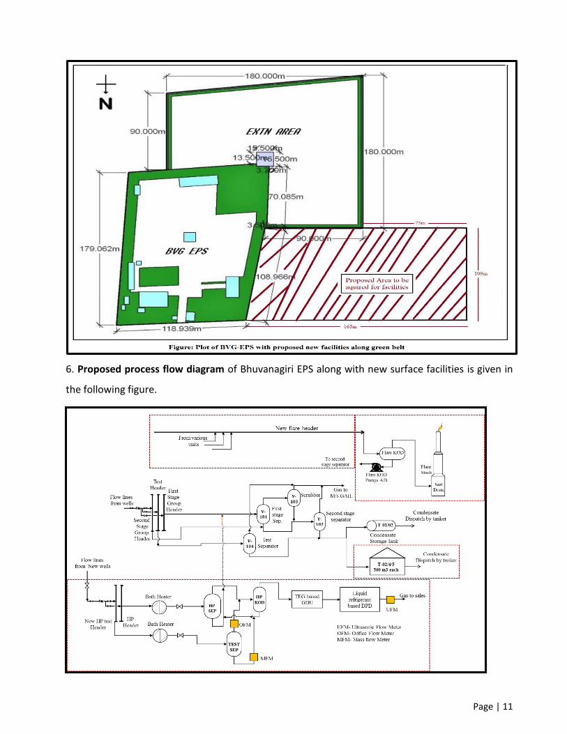
5. Layout Plan: Additional area requirement for setting up new surface facilities at BVG-EPS will be
approximately 4.5 acres including green belt. Existing Plot plan along with additional land required
for augmentation of surface facilities is given in the following figure.
Page | 11
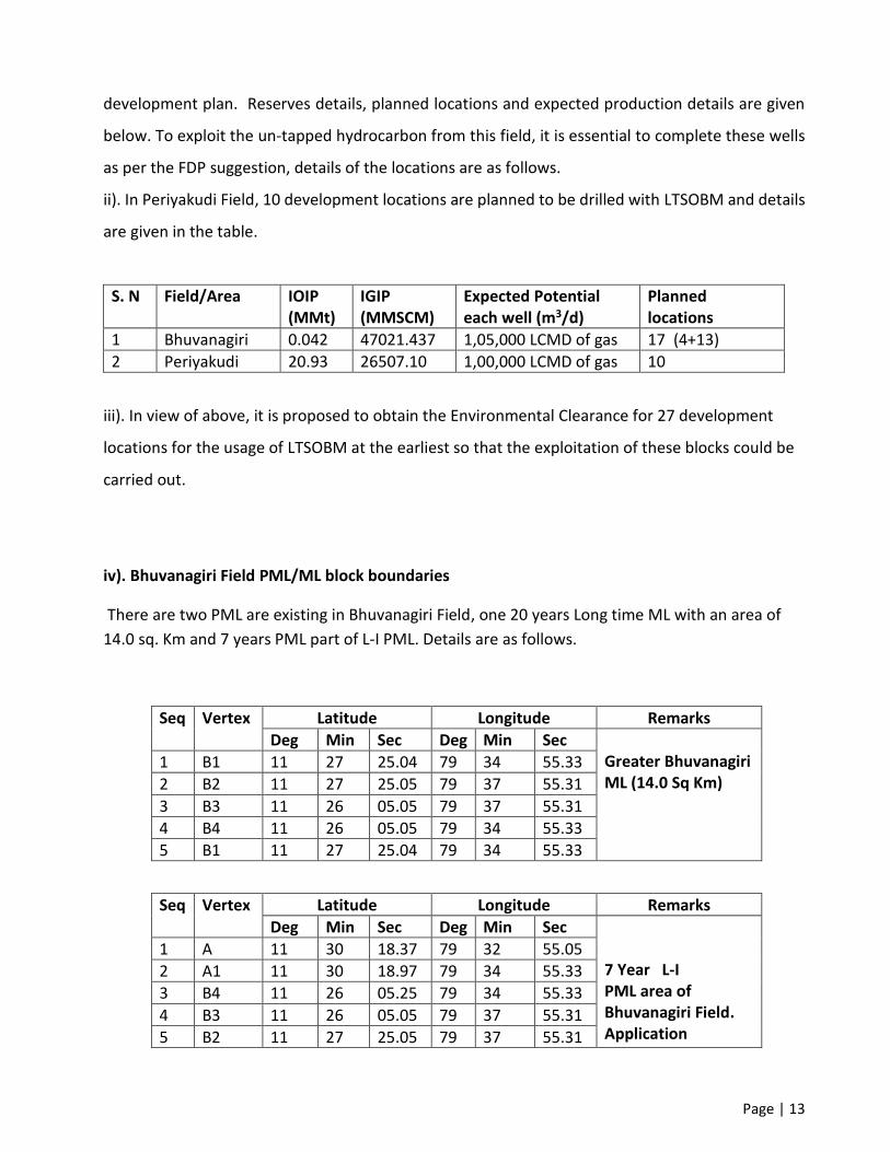
6. Proposed process flow diagram of Bhuvanagiri EPS along with new surface facilities is given in
the following figure.

Page | 12
Thus, there is urgent need of enhancing the oil and gas processing facility by erecting and operating
BVG-EPS to handle the peak production of Phase-I about 186m3/day of condensate and 4.25LSCMD
of gas to adequately monetize the resources in the interest of nation.
4. Project Capital Investment anticipated
4.1 Bhuvanagiri Field:
Phase-I development will be executed by contract services and Phase-II development will be
completed by ONGC resources.
Phase-I development CAPEX (Wells + facilities) is approximately Rs. 750 Crore
Phase-II development CAPEX is approximately Rs. 1700 Crore
4.2 Periyakudi Field:
Development CAPEX envisaged is about Rs. 1300 Crore.
5. Justification for Environmental Clearance
Hydrocarbon accumulation has been established in Bhuvanagiri field in Bhuvanagiri
Formation of Upper Cretaceous age. As on date 12 exploratory wells were drilled and proved the
presence of huge quantity of commercial hydrocarbon in tight reservoir of Bhuvanagiri Field. Due
to the poor development of reservoir facies and unconventional nature of the reservoir the field
was remain as unexploited. ONGC is committed to fulfil the energy requirement of the country,
Bhuvanagiri and Periyakudi are challenging fields and with the induction of right technology the
untapped hydrocarbon from unconventional reservoirs can be monetized.
5.1 Justification for LTSOBM usage
i). A comprehensive study has been undertaken by M/s. Blade Energy and submitted the detailed
plan for the Bhuvanagiri Field development. 17 development wells have been proposed under two
phased development plan with Low Toxicity Synthetic Oil Base Mud (LTSOBM) usage in final phase
drilling for avoiding complications and multi stage Hydro fracturing for enhanced hydrocarbon
recovery. Envisaged peak gas production is 28 LSCMD of gas after implementation of Field
Page | 13
development plan. Reserves details, planned locations and expected production details are given
below. To exploit the un-tapped hydrocarbon from this field, it is essential to complete these wells
as per the FDP suggestion, details of the locations are as follows.
ii). In Periyakudi Field, 10 development locations are planned to be drilled with LTSOBM and details
are given in the table.
S. N Field/Area IOIP (MMt)
IGIP (MMSCM)
Expected Potential each well (m3/d)
Planned locations
1 Bhuvanagiri 0.042 47021.437 1,05,000 LCMD of gas 17 (4+13)
2 Periyakudi 20.93 26507.10 1,00,000 LCMD of gas 10
iii). In view of above, it is proposed to obtain the Environmental Clearance for 27 development
locations for the usage of LTSOBM at the earliest so that the exploitation of these blocks could be
carried out.
iv). Bhuvanagiri Field PML/ML block boundaries
There are two PML are existing in Bhuvanagiri Field, one 20 years Long time ML with an area of
14.0 sq. Km and 7 years PML part of L-I PML. Details are as follows.
Seq Vertex Latitude Longitude Remarks
Deg Min Sec Deg Min Sec Greater Bhuvanagiri ML (14.0 Sq Km)
1 B1 11 27 25.04 79 34 55.33
2 B2 11 27 25.05 79 37 55.31
3 B3 11 26 05.05 79 37 55.31
4 B4 11 26 05.05 79 34 55.33
5 B1 11 27 25.04 79 34 55.33
Seq Vertex Latitude Longitude Remarks
Deg Min Sec Deg Min Sec 7 Year L-I PML area of Bhuvanagiri Field. Application
1 A 11 30 18.37 79 32 55.05
2 A1 11 30 18.97 79 34 55.33
3 B4 11 26 05.25 79 34 55.33
4 B3 11 26 05.05 79 37 55.31
5 B2 11 27 25.05 79 37 55.31
Page | 14
6 C1 11 27 25.03 79 40 20.30 submitted to DGH for ML conversion
7 D1 11 24 32.04 79 40 20.30
8 D 11 24 29.94 79 32 56.83
9 A 11 30 18.37 79 32 55.05
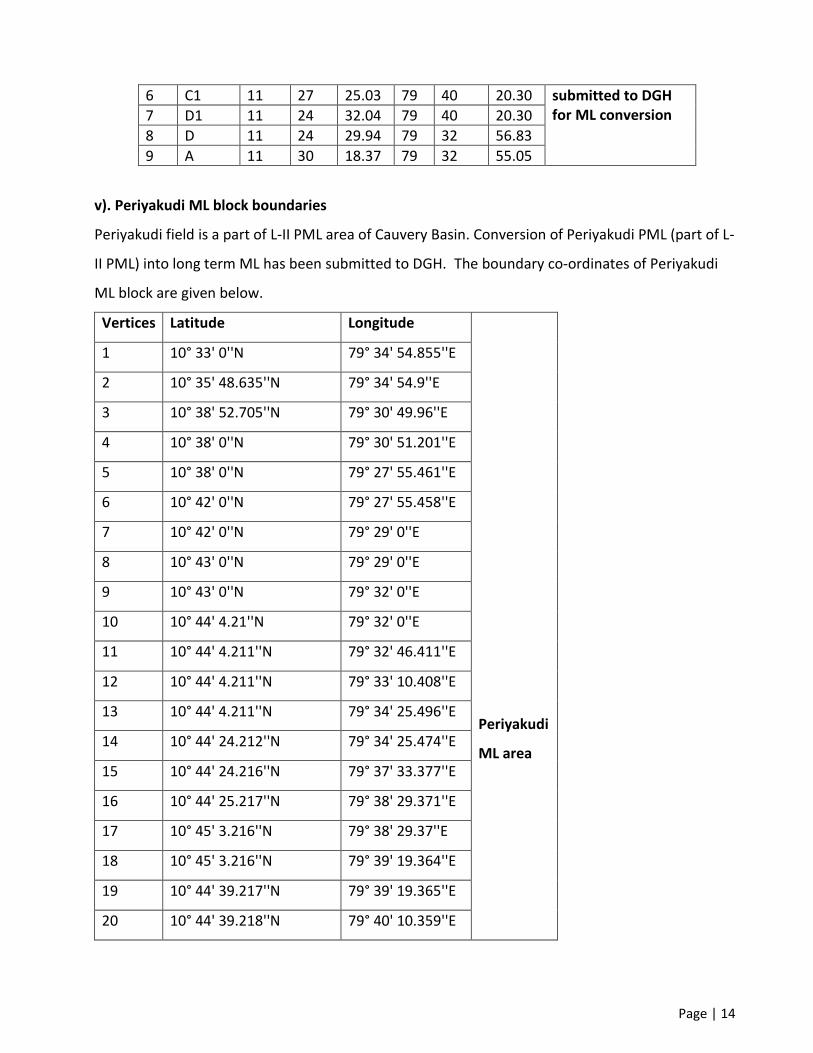
v). Periyakudi ML block boundaries
Periyakudi field is a part of L-II PML area of Cauvery Basin. Conversion of Periyakudi PML (part of L-
II PML) into long term ML has been submitted to DGH. The boundary co-ordinates of Periyakudi
ML block are given below.
Vertices Latitude Longitude
Periyakudi
ML area
1 10° 33' 0''N 79° 34' 54.855''E
2 10° 35' 48.635''N 79° 34' 54.9''E
3 10° 38' 52.705''N 79° 30' 49.96''E
4 10° 38' 0''N 79° 30' 51.201''E
5 10° 38' 0''N 79° 27' 55.461''E
6 10° 42' 0''N 79° 27' 55.458''E
7 10° 42' 0''N 79° 29' 0''E
8 10° 43' 0''N 79° 29' 0''E
9 10° 43' 0''N 79° 32' 0''E
10 10° 44' 4.21''N 79° 32' 0''E
11 10° 44' 4.211''N 79° 32' 46.411''E
12 10° 44' 4.211''N 79° 33' 10.408''E
13 10° 44' 4.211''N 79° 34' 25.496''E
14 10° 44' 24.212''N 79° 34' 25.474''E
15 10° 44' 24.216''N 79° 37' 33.377''E
16 10° 44' 25.217''N 79° 38' 29.371''E
17 10° 45' 3.216''N 79° 38' 29.37''E
18 10° 45' 3.216''N 79° 39' 19.364''E
19 10° 44' 39.217''N 79° 39' 19.365''E
20 10° 44' 39.218''N 79° 40' 10.359''E

Page | 15
21 10° 45' 3.217''N 79° 40' 10.361''E
22 10° 45' 3.217''N 79° 40' 25.357''E
23 10° 45' 6.826''N 79° 40' 25.357''E
24 10° 45' 7.219''N 79° 41' 58.346''E
25 10° 45' 7.221''N 79° 43' 25.337''E
26 10° 45' 7.363''N 79° 44' 0''E
27 10° 42' 52.503''N 79° 44' 0''E
28 10° 42' 35.37''N 79° 40' 46.36''E
29 10° 33' 0''N 79° 40' 46.379''E
1 10° 33' 0''N 79° 34' 54.855''E
5.2 Justification for expansion of surface facilities at BVG-EPS
1. All the existing Oil and Gas processing facilities in the Bhuvanagiri field i.e. BVG-EPS are
maintaining third party certified Environment Management System based on ISO 14001, integrated
with Quality Management System (ISO 9001) and Health and Safety Management System (OHSAS
18001). This implies that all the environmental risk along with health and safety risks have been
identified and being managed. All these facilities are operating under consolidated consent and
authorization from Tamil Nadu Pollution Control board (TNPCB). Regular monitoring of stacks,
ambience, produced water, noise and vibration, haz. waste etc. is carried out by third party and
returns are filed with TNPCB.
2. Proposed facility i.e. BVG-EPS will also maintain the same management system to address its
environmental issues to minimize the impact of its product, activities and services on the
surroundings.
3. Construction of proposed facility will result in development of infrastructural facility in the area
for the benefit of people residing nearby.
4. Construction of proposed facility will involve large number of skilled and unskilled workers. This
would generate employment for the locals.

Page | 16
5. Cauvery Asset has been the flag bearer when it comes to Corporate Social Responsibility (CSR)
schemes for the area will help in improving the living conditions of societies in this area.
6. Bhuvanagiri field is holding Mining Lease (ML) and exploration and production activities are being
carried out since 1987.
7. Coordinates of proposed BVG-GCS (up gradation of EPS with new facilities) are given below;
The final area will be decided after land acquisition is completed.
Sl No. Location EPS Surface Co-Ordinates Remarks
Latitude Longitude
1 A 11°26'23.5"N 79°36'57.2"E Area ‘ABCDEFGH’ belongs to existing BVG-EPS
2 B 11°26'17.6"N 79°36'56.8"E
3 C 11°26'17.5"N 79°36'55.6"E
4 D 11°26'14.4"N 79°36'56.1"E
5 E 11°26'13.8"N 79°36'49.7"E
6 F 11°26'19.9"N 79°36'49.9"E
7 G 11°26'23.5"N 79°36'57.2"E
8 H 11°26'23.2"N 79°36'53.3"E
9 I 11° 26' 23.441''N 79° 36' 47.956''E Belongs to proposed BVG-EPS. The final area will be decided after land acquisition is complted.
10
J 11° 26' 20.01''N
79° 36' 47.498''E