practical wirei,ss, june contr lof selectiv y...
TRANSCRIPT

NE WN ES
PUBLICATION
EJ.CAMM
©DFU EVERY
WEDNESDAY
PRACTICAL WIREI,SS, June 29th 1910.
CONTR LOF SELECTIV
A IFS\
Y See page. 15
11
Radio Service Work is Booming! Get a Good Job with the Knowledge in this Im portant Book!
PRACTICAL WIRELESS SERVICE MANUAL F. J. 'AMM A complete dand up-to-date guide Invaluable to all whose work concerns the tracing of faults and the effecting of repairs to all types of wireless receivers. Over 200 Illustrations.
6i a NET From oil booksellers, or b post 6/6 from the Publisher, GEORGE NEWNES, Ltd. (Book Dept.), Tower Flouse, Southsr,ston Street, Strwid, Lustlos, W.C.2.
ALlY 1.
VOL 16. O. 4O6 'J 1940.
*
____________
Va1ve Standardisation
- -, -,-------- - Differential Condensers
L ' Thermion's ç
Commentary I
The Control of ct7ityand Quality 4
Practical Hints .
r A Remote Control
I
I I
De:ice
Quick4ire Servicing A TWEL'VERANCE TEST..METER
- -' Readers' Letters
PDF compression, OCR, web optimization using a watermarked evaluation copy of CVISION PDFCompressorPDF compression, OCR, web optimization using a watermarked evaluation copy of CVISION PDFCompressor

AC. Fury Four (SG, SG, D, Pen) - PW2O Five-valve Blueprints, is. 6d. each .Shrt-a.sw A4aptcr1j.) .. - AW450 AC. Fury Four Super (SG, SO, D, Super-quality Five 2 HF, D, RC, Superhet Converter (1/-) .. - AW457
Pen) ........ - PW34D Trans) ......... W2O 13.L.1XL.C. Short-wave Converter AC. Hall-Mark (HF Pen, D, Class B Quadradyne (2 SG, D, LP, (1/-) ........ .. Muy '30 WM4L5
push-Pull) ...... - PW4 Class B) - WM344 Wilson Tone Master (1/-) June'30 WM400 Universal Hall-Mark (HF Pen, D, Ìew Class B Five (2 SO, D, LP, - The W.hI. AC. Short-wave Con-
Puah-ftll) PW47 Class B) ........ - W1l(340 verter (1/-) ......... - WM408
e.
(Pen), LP, CI. 33) Tise AdmiraI ' Four (11F Pen,
11F l'en, D, Pen (RU)).. Mai,ss Operated
Two-valve : Blueprints, Is. each. AC. Twin (D (Pesi), Pen) A.C.-D.. Two (SG, Pow) Seleebane AC. Raviiogram Two
(B, Pow) ........ Three-valve : Blueprint!, II. each. Deuble-Diosle-Triosle listen (HF
Peu, DDT, Pen) D.C. Ace (SG. D, Pen) AC. Three (SG, D, Peu) AC. leader (HF Pcn,p, Pow) 11. Premier (11F Pen, D, Pen) Unique (HP Pen, D (Pen), l'en) Armaula Mains Three (UF Pen, D,
Pen) F. J. Camni' s A.C. A ti-Wave Silver
Souvenir Three (11F Pen, D, Pen) "All-Wave" A.C. Three (D, 2
LT (BC)) ........ A.C. 10341 Sonotone (HF Pen, UF
Pen, Westector, Pen) Stains Record Alt-Wave 3 (HF
Pen, D, Pen)
Fane-valve Rlucerints. Is. each.
12.2.38 PWS3 (1(0, D, Trans) ..... . l0!i34 Lucerne Straight Three (D, RC,
3.9.38 PWtM) Traen) ......... - Tranusportable Three (SC, D, Pen) - Siinple-rune Three (SG; D, Pen).. Jvene '33 F.coiiousy-Pentode Three (SO, D, - PW18 Pen) ......... Od. '33 - PW3I "W.M. 1934 Standard Three
(S4J,D,Fen) .. .. .. - - PWIt) £3 s. Three (SC, D, Trane) -. Mar. '34 1035 £41 Cs. Battery Three (SG,
D,Pen) ........ - - PW23 l'TI' Three (Pen, D, Pen) .. - - PW25 Certainty Three (SG, D, Pen) -. - - PW2O Minitube Three (SG, D, Trans) . Od. '35 7,1.39 PW35C All-Wave Winning Three (SO, D,
PW35B Pen) ....... - - PWI6A Four-valve Blueprints is. Gd. each.
- PW3S 65v. Pour (SG, D, RC, urans) - 2HFFour(2S0,D,Pen) -- -
- PWSO Self-contained Four (SO, D, LP, Clairs B) ........ Aug. '33
- PWS4 Lucerne Straight Four (SG, D, 1Y Trans) ...... -
- PWS6 £5 5v. Battery Four (JTF, D, 2 LP) Feb. '35 The U.K. Four (SG, SG, D, Pen) - -, PW7O The Auth Straight Pour (UF Pen,
11F Pen, DDT, l'en) .... Apr. '36
AW435 15O, D, LP, P) ...... 22.7.30 Sugerhet : Blueprint, is. Gd.
AW437 Simplified Short-stave Super -. Nor. '35 WM271 W11327 Mains Operated. -
Twc-valve : Blueprints, Is. each. WM337 Two-valve Mains Short-waver (D,
l'en) AC. ...... 13.1.40 WM251 W.M." Long-wave Converter -
Three-valve Blueprint, Is. J6uuigrator(SG, D, Pen) AC. -
WM371 WMISO Four-valse : Blueprint, is. Ed. WM093 Stanslarsl Four-valve AC. Short-
uaver(SO, D, RC, Trans) .. - MISCELLANEOUS.
\%M400 SW. One-valve Converter (Price Cd.) ........ -
AW370 FAit Isusiast's PoSeer Amplifier (1/6) - AW421 Listener's 5-watt AC. Amplifier
(1/C) ......... WM331 Radio Unit (2V.) for VM392 (1f-) Net'. '35
Harris Idectrogram battery am- WM3S) plifier(lf.) .. . . - WMISI De Luxe Concert AC. Electro- WM32,4 gram (1f.) .. Mur. 36 :, Ness' style Short sv'sve Adipter WM404 (/-)
Trietle Cearger (Cil.) -
W1s1383
WM3U7
AW453 WM380
WM352
WM3O L
AW329 WM387
W M 302 WM3OS
- WM390
WM403
WM388 AW4432
(11F Pen, D, Pen) .. .. 221.38 1'W84 F. J. Camm's "Sprite" Three AMATEUR WIRELEU ANO WIRELESS MAGAZINE
(HF Pen,.D, Tet) 2G.3.38 PW87 CRYSTAL SETS. The" flurrlcane"All-WaveThree Blueprints, 6d. each.
(SG, D (l'en), Pen) .... 30.4.38 FWSO Foui-Station Crystal Set.. .. 23.7.38 AW427 F. J. Camm's "Push-Butthrs" 1934 CryStal Set .. .. .. - A\*444
Three (HF Pen, 3) (Pen), Tet 30,38 PW92 150-mile Crystal Set .. .,.- . AW4SO
Four-valve Bluprints, is. each STRAIGHT SETS. Battery Operated. Senotene Four (SG, D, LP, Pj- L,3,37 'w Oce-valve Blueprint. Is. Fury Your (2 SG. D, Pen) &&37 PW3I B.B.C. Special tJoe-valver - AW3S7 Beta Universal Four (SO, D, LP, Two-valve Blueprints, is. each.
Cl. E) ....... Nuirlen Class B Four SO, D
- PWI7 !siele*ly Banger Two (D, Trans.) -. AWISS
(SG), LF, Cl. B) ...... - FW34B Full-volume Two (8G det, Pen), - , AW32 Fury Four Super (SO, SG, D, Peu) - PW34C Lucerne Minor (1), Pen).. - .'uW426
Battery HalL.hlark 4 (1fF Pen, A Modern Tsvo-valver .... - WM400
D, l'uslu-PuIl) ...... - PWI6 Three-valve Blueprints, le. each. F. J. Gamm's "Limit" All-Wave II, Trans) - AW412
Your (HF Pen, D, LP, P) 269.36 PWC7 Lucerne Ranger (SG. 1), Trans) - AW422 "Acme" All-Wave 4(HF Pen, D en s Thr De Luxe Version
SHORT-WAVE SETS. Battery Operated. One-valve Blueprints, is. each. S.W. Ouue-valverforAuserica .. 15.10.38 AW429 lieuse Short-Waver ..,, - AW452 Two-valve Blueprints, is. each. Ultra-Short Battery Two (SG, det,
Pen) ...,,., Feb.'36 WM402 Houne-1nadc Coil Two (D, Pen) - AW440 Three-valve : Blueprints, 1S.(each. )'sorlsl-ranger Short-wave 3 (D,
W., Trans) ...,.. - AW355 Expenmenter's 5'metre Set (D,
Trans, Super-regen) .... 30.634 AW438 The Carrier Short-waver (SG, D, P) July'35 WM390 -. Four-valve Blueprints, is. 6d. each: A.W. Short-wave World-beater
(HF Pen, D, B, Trans) .. - AW436 Empire Short-waver (SG, D, RC,
Trans) ..,,.., - WM313 - Staisdarul Four-valve Short-waver
(Trans)) ........ - PW1O SHORT-WAVE SETS. Battery Operatel. house Lover's Ìew AlI-Fjectric -
Sixty Shilling Three (D, 2 LP - One-valve : Blueprint, i . Three (SG, D, Traue) AC. .. - AVi73 3
(RC & Trans)) -
PW34A Ssmple S.W. One-valver . . 23.12.39 PWSS AC. Three (11F, Pen, Leader Three (SG,D, Poe) :: J'W35 D, Pen) ........ - WM314 Summit Three (HF Pen 1) Pen) - PW37 Two-valve : Blueprints, is. each. 215 15v. 3036 A.C. Rasiiogrsiii All 4'esstodc Three (Ri? j'en, J) Midget. Short-wave Two (D, Pen) - PW38A (11F, D, l'en) ...... Jan. '36 WM4O1
(Pén), Pen) ...... 20.5.37 PW3O The Fleet" Short-wave Two Four-valve Blueprints is. Ed. each. Ball-Mark Three (SG, D, Pow) . - PW41 - D (UP Pen), Pesi) .... 27.8.33 PWO1 All Metal Four (2 SG, D: Pen) .. July'33 WM320 Ball-MarkCadet(D, J.F, Pen (RC)) 1. Camm's Silver Souvenir
16.3.35 PW48 Three-valve: Blueprints, is. each. Ifarrei' Jubilee Batliograni (HF '35 j' (HF
Pin, J) (Pen), l'en) (All-Wave Rx4)erinsentere Short-wave Three Pen, D, LP, P) . ..... May WM36
Three) 13.415 PW4O (SG,D,Fosv) .. - PWSOA SUPERHETS. ........ Cameo Midget Three (D, 2 LI? The Predà 3 (D, 2 LF (C ani Battery Sets : Blueprints, is, Ed. each.
(Trans)) ........ - i'wi Trans)) ........ - PWO3 ModérnSuperSenior ,.,. - WM3IS 1936 Sonotone Three-Four (11F The Band-Spread S.W. Three -. VarvityFour ...... Oct. '35 WM305
Pen, HF Pen, Westector, l'en) - PWS3 (HF l'en, 1) (Pen), Pen) .. L10.38 PWOS ,,TeJtequestAll-Waver .., June'30 WM4O7 Battery All-Wave Three (D, 2 LP PORTABLES.
W35 Super-Five Battery (Superhet) - WM379 (RC)) .........
The Monitor (11F l'en D, Pen) PW5S
- Thret-valve : Blueprints, is. each. Mains Sets : Blueprints, is. Ed. each. Heptexte Super Three AC. .. May'34 WM3E9 ..
The Tutor Three (HF ben, D, Pen) 21.3.36 PW(2 J. Camm's ELF Three-valve Portable (HF Pen, D, Pen) .. - PWO5
"W.M." Radiograin Super LC. - W113t36 The Centaur Three (SG, D, P) . 14.8.37 1'W64 Parvo Flyweight Midget Portable PORTABLES. -
F. J. Camus's its-cord AU-Wave (844, D, l'en) ...... 3.6.30 PW7I Jour-valse: Blueprints, is. 6d. each. Three (MF Pen, D, Pen) .. 31.10.36 PW69 Holiday Portable (SG, D, LP,
The "Colt" All-Wave Three (D, Four-valve : Blueprint, is. '- - Cluns B) ......... - AW303
2 LP (RC & Traiss) .... 18.2.39 PW32 "Imp '-Portable 4 (D, LP, LP Faisìily Portable (HF, D, RC, TIse "Rapide" Straight 8 (D,
. (Pen)) ......... - PW86 Trans) ........ - AW447 2 LP (RC & Trans)) -. ..
P; J. Camus's Ora'le All-Wave 4-I'll? L'W82
- MISCELLANEOUS Two 11F Portable (2 SG, D, QP21)
Three (HF, Det., Pen) ,... 1038 "Ta-ibatid" All-Wave Three
25.8.37 PW7S Blueprint, 1v. S.W; Goevertee-Adapt.cr (1 valve) -
.
PW4SA ..........
Tyers Portable (SG, D, 2 Trans) - WM363 WM367
PRACTIOAL WIRELESS ¡Jethoflsssie A
CRYSTAL SETS Bluepeints, Bd. each. 1937 Crystal Receiver - me Junior " Crystal Set .. 27.8.38
STRAIGHT SETS. Battery Operated. Qne-valve : Blueprints, lu. each.
fl-Wave lJnipcn (l'entole - .. - Beghsners Une-volver .. .. 19.2.38 The "Pyraasitl" One-valver (HF
Pen) ........ 27.8.38
Two-valve Blueprint, 1v. The Signet Two (D & LT) .. 24.9.38
Three-salve : Blueprints, is. each. Seleethne Battery Three (D, 2 LT
No. of SUPERHETS. lueprin! Battery Sets : Blueprints lu. each.
£5 Superlict (Three-'eaIv . 5.0.37 F. J. camus's 2-valve Superhet
FW7S Mains Sets Blueprints, Is. each. AC. £5 Superhet (Three-valve) - D.C. £5 Superhet (Three-valve) - Universal £5 Superbet (Three-
FW3IA valve) -. PW85 F. J. camus's AC. Superhet 4 - -
F. J. camus's Universal £4 Super- pwtis bet 4 ......... -
Qualitone" Universal Four . - 1(l.L37
PW7O Four-vaine : Doubte-cided Blueprint, lu. 6d. Punuh Button 4, flattery Motel -
- PuseS Button 4, AC. Mains Model -.
1940, and alter) - 5d. Post Paid
.',nIaleuI' Wiretess 4d. Wiletess Magazine ...... .1/4 The index letters which precede the Blueprint
PW4O Number Indicate the periodicai in which the des- PWSZ crlption appears: Thus P.W. refers to PRACTICAL
WIRELESS. A.W, to A,ealeur Wireless, W.M. to Wire- less Masgzine,
PW43 Send (preferably) a postai order to Cover the Cost of tbe blueprint. aliti the issue (stamps over 6d. unacceptable) to PRACTiCAL WIRELESS Blueprint Ip George Newnes Ltd., Tower house. South- PW44 asnpton Stzeet, Strand, W.C.2.
PW59
PWOO Mains Operated. PWZ3 Two-valve Blueprints, Is. each.
Consoelectric Two (D, Pen) AC. - AW4td Fnomy AC. Two (D, Trans) A.C. - WM2SO
FWOS llnicorn A.C.-D.C. Two (D, Pen) - WM394 -
Three-valve : Blueprints, is. each.
PRACTICAL WIRELESS June 29th, 1940
These Blueprints are drawn full size.
dons of these sets can In some cases be supplied at I the following prices which are additional to the cosi I
ractical Vire1ess of appropriate Issues containing descrip-
of tlw8luepiint. A dash before tut Blueprint Number I
1E 1 R I S E RSnI C E indicates that the issue IS Out of print.
Practical Wireless (issues dated prior to June I ist, 1940) 4d. Post Paid (Issues dated Juno ist,
PDF compression, OCR, web optimization using a watermarked evaluation copy of CVISION PDFCompressorPDF compression, OCR, web optimization using a watermarked evaluation copy of CVISION PDFCompressor

Adèle \stire and Cole Porter. . .-. . _. charge of the feature.
Hour, The Prisoner of Zenda" in a new adaptation by Barbara Sligh will have the first of a series of weekly episodes.
College Rhythm THE Three College Boys, who are students
at a Glasgow Medical School and who, instead of working, sing their way through college, will take part in a short variety programme on June 28th, with Harry Carmichael and Dave Goldberg (guitar). While on holiday in France, they gave a guest concert with the Quintette of the Hot Club of France, and their performance earned congratulations and a magnum of champagne from two celebrities present,
The Editor will be pleased to rongider articles of a practical nature suitable for publication in PRACPICAL WIRELESS. Such articles should he written on oar, side of Use paper only, and should contain lise naisse and address of the gender. Whilst the Editor does not hold himself responsible for munuscripts, ecery rifar? will be made to return theni if a stamped and addressed envelope is enclosed. Alt corres pondence intended for the Editor should be addressed: The Edilor, PRLCTICÂL WIRELESS. eeorge Nss'nes, Ltd., Tower Horse, Southampton Street, Strand, W.OE.
Owing to the rapid progress i0 the design of erireleso apparatus and io our efforts to keep our readers in touch with the latest developments, we give no warrunty i/sot apparalus descnï.sed in our columns is not tise sObject of letters patent.
Copyright in all drawings, photographs and articles putsti8lsed in PRACTICAL \VERELESS is specifically reversed throng/soul t/s countries signa- tory to the Berne Convention asid tise U.S.A. .Reproducliona or imitations of any of these are therefore r.rpresaly forbiddrn. P050TICAL Wins- LESS mess borates Amateur Wireless."
,Creswell.
Return of Lrlme Magazine" AFIER more than a month in which to
take stock, "Crime Magazine" will return to the Home Service and Forces programmes on July 2nd, but at a slightly later hour in the evening. It is expected that practically all the features which were included at the end of the first, series will be retained. Ex-Detective Inspector Jack Henry, late of New Scotland Yard, will again be heard in a further series of adventures based on incidents of real life; Billy Milton will appear in "Meet the Arrow," a series of detective occasions written by Ernest Dudley; and Bill Maclurg will again be in
Engitieeis on the subject.
Literary Productions THE B.B.C. announces that on July 8th
tite first instalment of a serial version of Rupert of Hentzau" will be broadcast in the Home Service. It has been adapted from Anthony Hope's book by Hugh Stewart. Charles Mason will play Rupert; Edana Romney Princess Flavia; Sebas- tian Shaw doubles the King and Rudolph Rassendyll, Frederick Lloyd is Colonel Sapt and Ronald Simpson Fritz von Tarlenheim. 'On July 11th, in the Children's
Gloria Brenl, the attractive singer who is often Diane, and Garry Cowan ; and that Eddie heard on 1/ic air with various Jamous bands.
Palmer will play the novachord.
slats of a "review" of the French Army and listeners will hear a portrayal of something of the spirit and tradition behind the army and how it is run and main- tained both in peace and war.
Editorial and Advertisement Office, " Practical Wtreless," George Newnea, Ltd.. Tower House, Southampton Street, Strand, W.C.2. 'Phone: Temple Bar 4363.
Telegrams Newnes, Rand, London. Registeredat the G.P.O. for transmission by j Canadian Magazine Post. t
F, "Three in a bar AMYSTERY play entitled "Three in a
Bar," to be bwadcast on June 27th, lias for its setting an old-fashioned public- house bar parlour. A mock trial, arranged by three customers in the parlour, leads to the apprehension of a murderer, who is "caught out," by the clever cross-question- ing of a police inspector and a police sergeant in disguise. The play is written by Peter Franklin and will be produced by Peter
LJ PRACTICAL T[.LEVISION* EVERY WEDNESDAY F. J. C 1% %I 1 w. J.bELANEY, FRANK PRESTON,
E O I E O O Y
j St.JJ:
Vol. XVI. No. 406. June 29th 1949. - H. J. BARTON CHAPPLE B.Sc.
ROUND THE WORLD OF. WIRELESS Simplified Valves
THE beginner may justly be excused some doubts concerning the wisdom
of manufacturers supplying such a wide range of valves. In the early days there were only a few types, and they were easily distinguished by references to indicate their main application. With improvements in circuit design various novel types of valve were introduced, many of which have ceased to exist, but a number are atill in existence. To add to the confusion the various makers use different references so
that it is not a simple matter to decide
a given alternative. In America this has been overcome by using a common refer- ence for all types, irrespective of the maker. Thus there is an R.C.A. 45, or a Raytheon 45 or a Sylvania 45, and it is only necessary in a
specification to quote a type 45 and the
constructor can use any make he desires with the knowledge that it will have the correct specification. Readers will remember recently an attempt to simplify matters in this country by the introduction of a special valve to suit any stag in a receiver, but it is obvious that there is a growing need foi a simplification in the valve classification, either by a limitation in types or a standardi - sation in reférence numbers. In this issue we give details of a proposal which has been made by the British Institution of Radio
Au Drapeaù Old Favourite, New Name AREVIVAL of the programme called IVEN the title "Nippit Fit and Clippit
"Au Drapeau," which was broad- Fit." few neonle would say they had cast at the end of April, will be produced even heard of th st3ry Yet it i realty one by Denis Johnston on June 29th. It con- of the most famous tales in the world, for
this is the Scottish version of Cinderella, which has been retold by March Syke and will be read by Christine at the beginning of the Children's Hour on June 27th. For Sassenachs "Nippit Fit and Clippit Fit" may be literally translated as "Nipped Foot and Clipped Foot," which explains the whole story. In the same programme, another of Helen Drover's "Songs of the. Clans" will be heard. This time she is deal- ing with Clan Scott, another of those which do not belong purely to the Highlands of Scotland. It includes some of the best songs and stories of the Scottish Border country, including "Blue Bonnets over the Border" and the story of "Muckle Mou'ed Meg."
r
Oscar Rabin and His Romany Dance Band
OSCAR RABIN and his Romany Dance
Band will be the' Band of the Week" beginning June 30th, and it is hoped that all the regular solo vocalists will be heard, including Harry Davies, Beryì Davies,
June 29th, 1940 PRACTICAL__WIRELESS
cflI W î !es s 309
PDF compression, OCR, web optimization using a watermarked evaluation copy of CVISION PDFCompressorPDF compression, OCR, web optimization using a watermarked evaluation copy of CVISION PDFCompressor

three types could equal any receiver at present available. In fact, a set in- corporating Types "A," "B" and "C" would result in a greater all-round advantage-at a lower cost to the manufacturer and consumerS
DICTIONARY OF METALS AND THEIR ALLOYS 5/-,
j by post 5/4.
PRACTICAL MECHANICS HANDBOOK 6/., by post 6/6. j MIoMa! e from or though Ne r from Ge Newnen Ltd Tower Houseeuthamon SL SW
controlled variable-mu AF. ampiffier, tetrode or triode; as a two-input circuit mixer and, of course, also as any constituent part of the above combinations.
Type "B" A universal output tetrode valve of the
type oapab1e of working at 100 screen voltage having an indirectly-heated cathode with a 25-volt 0.3 amp. heater.
Type "C" A two-system rectther of the type in
which all electrodes are brought out separately, having indirectly-heated cathodes with a 25-volt 0.3 amp. heater.
Receivers designed on the use of these
A COMPLETE LIBRARY OF STANDARD WORKS By F. J..CAMM.
PRACTICAL WIRELESS ENCYCLOPAEDIA 7/6, by post 8/.. EVERYMAN'S WIRELESS BOOK 5/., by post 5/6. SIXfl' TESTED WIRELESS CIRCUITS 3/6, by post 3/lo. COILS, CHOKES and TRANSFORMERS 3/6, by post 3/10. PRACTICAL WIRELESS SERVICE MANUAL 6/-, by post 6/6. WORKSHOP CALCULATIONS, TABLES & FORMULAE
3/6, by post, 3/lo. NEWNES' SHORT-WAVE MANUAL 5/., by post 5/4. THE HOME MECHANIC ENCYOPEDIA 3/6, by post 4/. WIRELESS TRANSMISSION FOR AMATEURS 3/6, by post 3/10.
present available, which approaches 1,000 different types.
The scheme in its final form is essentially based around five specific types of valves, as fhllows
Type " A" This is a screened triode-hexode of the
type in which the first grid of the hexode is cornuion with the triode-grid, having an indirectly-heated cathode and a 6.3 volt 0.3 amp. heater.
lu addition to its customary use as a frequency changer, such a valve can also be used as an R.F. variable-mu amplifier; a variable-mu I.F. amplifier and diode for A.V.C. as a demodulator diode and as a
in the initial stages of the scheme. The ultimate national production of the
proposed five types of valves would actually aid the valve manufacturing industry by ultimately eliminating "frozen" stocks of diverse types while similarly aiding pro- duction on the restricted amount of material now available, for home and particularly export trade.
This is important in view of the following essential imports:
Pure nickel: Scandinavia and U.S.A. Pure molybdenum: main sources
U.S.A. Eliminating two hundred odd types of
glass bulb shapes which, owing to cut-off supplies from Belgium and Czechoslovakia,
4. The specialisod types of vÍves manufactured have always been less than lo per cent, of the normal Receiver Valve business, and the adoption of the scheme put forward will undoubtedly expedite production of the specialised types which may still be required for the Defence Departments, the B.B.C. and the G.P.O.
Summary Consideration and development of these
proposals by a technical committee repre- senting the industry will undoubtedly contribute to our occupying a more influential position in the world market. both now and after the war.
technicians such as tool makers and jig and tool designers.
4. Save a considerable amount of raw material which is now absorbed unnecessarily.
5 Make good some of the loss of essential import material.
6. Alleviate difficulty in Lidio Servicing. It should be noted that the first step
towards achieving the ideal is the immediate all-round adoption of the existing range of 6.3 volt 0.3 amp. valves. This range, including its higher voltage companion types, consists of a mere twenty types as against the formidable list of types at
Type "D" A battery valve type, analogous to
Type "A," having 1.5 volt 0.05 amp. filament. Its functions are identical to Type "A."
Type "E" Analogous to Type "B," but having a
centre-tapped 2.8 volt 0.05 amp. filament. Types "D" and "E" can be used to
fulfil the majority of requirements outside the field of utility of Types "A," "B" and "C," but two or three of the additional existing 1.5 valves would also be reo uired
3. The technical objection that certain specialisecl apparatus will stiii require specialised types of valves is undeniable, but does not materially affect the scheme, since of the ten to twelve million radio receiver valves absorbed by the Radio Receiver Industry, well over 80 per cent. are used in sets in which the five specified types of valves could be satisfactorily used. The other 20 per cent, is made up of Replacement Valve business which, if the above proposed scheme is put into effect, could be easily satisfied for the next eighteen months to two years from the existinq available stocks of diverse tvoes.
Some Interesting Proposals which Have Been Put Forward by the British Institution of Radio Engineers
THERE have been many suggestions
in the past for a standardisation and limitation in the number of
valve types. Many interesting schemes have been formulated, and the standard- isation committee of the British Institution of Radio Engineers have reoently published a report which has been submitted to the Ministry of Supply, Ministry of Labour and the Service departments regarding a scheme proposed by Mr. J. A. Sargrove. It is claimed by the B.I.R.E. that adoption of the proposals set out would enable the Radio Industry to:
1. Satisfy home demand but
2. Increase export trade. 3. Make available for other important
industries many highly-skilled
Such features as automatic inter-station noise suppression, automatic volume control, post demodulator, automatic volume level maintainer, would, with the incorporation of these three types, be included without difficulty, thereby proving of sales advantage in the home and export field.
The scheme envisages all receivers as A.C./D.C. supply types, thus entirely eliminating the need for mains transformers and, in the case of the smaller sets, also eliminating the smoothing choke, thereby saving a considerableamount of high-quality transformer (or Swedish) iron and copper (former important source-Belgium).
Adoption of these three types would, it is estimated, solve 70 to 80 per cent. of the market requirements for radio receivers.
are at present being manufactured in this country, to the detriment of other glassware export.
A Summary of Discussion of the Objections to Mr,. J. A. Sargrove's Proposals 1. The standardised component parts
suggested do not affect the ultimate per- formance of receivers or impose Jimits on
-' the design of specialised receivers; the resultant performance of the suggested design can be confirmed by &vkpendent and qualified Radio Engineers.
2. The scheme will provide the Radio Manufacturer and Designer with an adequate but limited number of comnonents.
310 PRACTICAL WIRELESS June 29th. 1940
uggested Va ¡ve Sta ¡ida rdisa tien
PDF compression, OCR, web optimization using a watermarked evaluation copy of CVISION PDFCompressorPDF compression, OCR, web optimization using a watermarked evaluation copy of CVISION PDFCompressor

really wanted. If it finds it8 way to the - -- - (Conti,,ed o, next page).
7
For manyears now the standard method of controlling reaction has been by using a reaction coil with a fixed number of turns of wire and fixed coupling, and to vary the current through this by connecting it in series with a variable condenser. This method is illustrated in Fig. 3. However, as shown here, it has certain drawbacks. The most obvious is that when the reaction condenser is set at a minimum there is no easy path for the H.F. component of the anode current of the detector valve.
The anode current of the detector valve may be considered as consisting of three separate parts. There is the steady direct current from the high-tension supply the rectifier speech current, and the amplified H.F. impulses. It is the last-named which are used for reaction purposes. They are fed back by means of the reaction coil, and superimposed on the input current. Now, apart from its use for reaction purposes, this H.F. part of the anode current is not
filament, as shown by the arrows in the left-hand diagram in Fig. 4. When the reaction is "turned-off" then the path of the H.F. impulses is from the anode to the fixed vanes B, thence via C, to the-filament. In any intermediate position the currents follow a divided path-partly through the
II pE,criiW I CalL
Fig. 3.-The orthodox method of controlling re-
action, using an ordinary variable con-
denser.
Fig. 4.-Showing I/se connection and the working of a differential reaction condenser.
HF. current when the reaction condenser is at zero. However, this value may be too large when a reaction condenser is sil in, for the total value of the by-puss condenser and the reaction condenser may be such as to by-pass sorne of the higher audio-frequencies and thus mar reproduction by loss of the higher notes. It is also found in practice that the use of the differential condenser provides a smoother control of reaction. It certainly provides a greater range of control than an ordinary condenser of equivalent value used in conjunction with a by-pass condenser, for when the differential is in the "full-on" position, nearly 100 per cent. of the current passes through the reaction coil, while when it is in the "off" position practically all of the current passes direct. to the
R 8 /1 8
mid point will be half the maximum value. This position is indicated in Fig. 2. It will be obvious from this that as the capacity of one condenser is increased that of the other is decreased, tho balance between the two sections being maintained.
Now there are several uses to which a differential condenser may be put, but we will deal first with its most common application, namely, its use as a reaction control.
By-passing the HF. Currents
#9
that it does not provide an alternative path for the H.F. component when it is set at zero, then a fixed condenser between
Fig. 2.-Plan of the anode and filament, as in Fig. 5, is all that vanes of a different ial is needed. Admittedly, this often provides condenser, showing a solution of the iroblem if the value of three different ,t- the fixed condenser is carefully chosen, ings of the condenser, but even so it has not quite the same
advantages as the differential method. For one thing, the value of the fixed condenser must be sufficiently large to by-pass the
a very easy exit, but when the reaction condenser is set to its minimum position it presents a very high impedance, and the "unwanted current" has no escape.
This is where the differential condenser comes in. It is connected as m Fig. 4. Now a moment's consideration shows us that whatever the setting of this condenser the by-pass effect is always constant. When the condenser is in the "full-on" position then the H.F. currents travel from the anode via the reaction coil, the fixed vanes A, and the moving- vanes C, to the
H.P C.
symbol and the general form of construction of the differential condenser and it will he seen that, from the theoretical point of view, it is really two condensers in series. There are two sets of fixed vanes mounted exactly opposite each other, and the spindle carries a set of moving vanes of standard shape and arranged in the same manner as on a normal variable condenser. The moving vanes are semi-circular in shape, so that when the spindle is half-way through its total arc of rotation each set of fixed vanes has an equal section of the moving vanes intermeshed with it Thus each separate condenser (considering them as two in 8eries) will be of equal valuo which at the
ing an H.F. choke in the anode Circuit of the detector immediately ibllowing the anode itself, as shown in Fig. 3 This choke acts as a barrier, and prevents its travelling farther than the anode of the valve. However, the choke is not in itself sufficient, and the "unwanted current" may be strong enough to force through this barrier unless some alternative path is provided. In Fig. 3 this alternative path is through the reaction coil and reaction condenser to the filament. It is indicated by the arrows. Now when the reaction control is "turned on fully," that is, when the reaction condenser is set somewhere near its maximum capacity, this path offers
Fig. 1.-The elements of a differential con- denser. Above, two ways of representing o
differential condense r diagrammatically.
reaction coil and A C, and partly through the path B C.
High Note Cut Off It may be argued that if the only draw-
back to the ordinary reaction condenser is
A Description of This Special Type of Variable Condenser and Its Various Circuit Applications
IT is sometimes noted that a specification includes a "differential" condenser- generally for reaction purposes. In
view, of the rather infrequent use of this type of component certain athateurs are not quite clear as to its special design and application, although the fact that it has three sets of piTates in comparison .with the usual two sets of moving and flxed vanes, may be known. Fig. i shows the theoretical
grid of the next valve it will cause dis- tortion and possibly actual howling. Again, if it is allowed to pass on round the anode circuit when an H.F. stage is used before the detector, then it is possible for it to cause undesirable back couplmg through the medium of the common impedance of the H.T. source.
The usual thing to do with this unwanted current is to impede its progress by includ-
-f' -1
June 29th, 1940 PRACTICAL WFELESS 311
For The Beginner
Tb Differential Condenser
PDF compression, OCR, web optimization using a watermarked evaluation copy of CVISION PDFCompressorPDF compression, OCR, web optimization using a watermarked evaluation copy of CVISION PDFCompressor

Ltd-Generation and transmission of radio waves. May 30th.
9472.-Standard Telephones and Cables, Ltd.-Generation and transmission of radio waves. (Cognate with 9470.) May 30th.
Specifications Published. 521637.-Radioakt.-Ges. D. S. Loewe.
-Deflection of cathode-ray beams. 521710.-Kolster-Brandes, Ltd., and
Arnold, J.-Remote-control sys-
Corporation-Loudspeakers. 521872.-Koister-Brandes, Ltd., and
Brigham, C E.-Thermi.omc valve circuits. -
521873.-Television and picture-trans. mission systems.
Printed copias of the full Published Specifications only, nay be obtained from the Patent Office, 25, Southampton , Buildings, London, W.C.2, at the uniform price of is. each.
Denmark AFEATURE telling listeners in this
country of the peaceful life which was led by the people of Denmark right up to the eve of thé German invasion on April 8th, 1940, will be broadcast on June 27th. The programme will consist of four scenes and will be performed by members of the B.B.C. Repertory CompanT. The story has been written by Marianne Heiweg and her father, J. -H. Heiweg, and will be produced by Laurence Giffiam.
Group Abridgmerds can be obtained from the Patent Office, 25, Southampton Buildings, London, W.C.2. either sheet by sheet as issued on payment of a subscription of Ss. per Group Volume or in
bound volumes, price 2. each. - e aOS)eOe4,)e4)fl)e e4)
tema, particularly for radio-re- N E W PATENTS Tbese particulars of New Patents of interest to
ceivers. 52l71l.L...Kolst,erBrandes, Ltd.., and readers have been selected from the Official
journal of Patents and are published by per' Beatty, W. A.-Antenna systems miesson of the Controller of H.M. Stationery and supporting structures. Office. The Official Journal of Patents Can 521714.-Standard Telephones aid he obtained from the Patent Office 25, South- ampton Buildings, London, w.c.i, price Is. Cables, Ltd. Terry, R. St. G., $
weekly (annual subscription £2 los.), and Beard, J' R.-Electromagnetic relay switching devices, particularly Latest Patent Applications, for radio equipments.
I 9819.-Cole, Ltd., E. K., and Kennedy, 521809.-Philco Radio and Television F. W. 0.-Tuning mechanism for Corporation .-1\iethod of assem- I radio-receivers. June 5th. bling and welding loud-speaker
984 1.-Hazeltine Corporation.-Tele- parts. vision systems. June 5th. 521808.-Philco Radio and Television
9703.-Philips Lamps, Ltd. - Wireless Corporation-Loudspeakers of the receiving-sets. June 3rd. eleetrodynamic type, and methods
9471.-Standard Telephones and Cables, of assembly thereof. Ltd-Generation and transmission 521810.-Philco Radio and Television of radio waves. (Cognate with Corporation. - Sound - reproducing 947OE)' May 30th. devices.
9470.-Standard Telephones and Cables, 52181L-Philco Radio and Television
"Up The Poll !"
A LLAN MAcKDN0N and Jack House' pioneers in writing for radio in
Scòtland, have resumed partnership and collaborated in what they have described as a "Mass Observation Musical Comedy," to be broadcast on June 27th. It is called "Up the Poll," and deals with events in a country whose happy people astonish the world. Nothing ever goes wrong in Morania, where the Government, having. studied publlc opinion surveys and Amen- - can magazines, employs a firm of professional public pulse-holders to find ont what the country wants. Thus the king is able to make perfect laws, because of the so-called infaffibility of the percentage polls. But, as the listener will find out, everything in the garden is not quite as lbvely as that. Allan MacKinnon is well known in the ifim world, having been jointly responsible with another Scot, Roger MacDougall, for the scripts of "This Man is News and "This Man in Paris."
,, - ._._l____ The Differential as a Volume full volume setting - - -
Control there is some slight - The connection for a differential reaction reduction of input Fig. 7.-Differential condensers used asvolume and seleciiitg controls.
condenser, shown in Fig. 4, is not the only owing to the fact possible arrangement. Another version is that there is still a small minimum capaóity devices in the one circuit, as in Fig. 7, shown in Fig. 6. Differential condensers existing between C and B. Secondly, that as more than sufficient control can are also used for a variety of other purposes variation of the control means slight usually be obtained with either one or besides reaction control. One of the best variation in the wavelength of the aerial the other. The variable coupler, how- known is as a volume control which works circuit, so that when the volume ever, is sometimes used, in conjunction by varying the aerial input. The circuit control is operated it may be necessary with an ordinary pre-set or variable is shown in Fig. 7. When the moving to readjust the aerial tuning conden- condenser, in series with the aerial a vanes of the ,condenser are completely ser. If this latter is ganged this will an additional selectivity control.
LATEST PATENT NEWS PROGRAMME NOTES
some multi-range coils there is considerable This type of volune control has the difference necessary in the setting of the advantage that it is very simple, noiseless reaction condenser on one wave-band in operation, and covers a large range, it compared with another. being possible to cut down the most
powerful stations to - wIiinr Jq dirI
11e condenser used as a variable coupler is represented at D E F. Here the action is precisely similar to that of the differential condenser A B O. In the same.way that A B C controls the input to the first valvé, so D E F controls that to the next valve
vantages are, firstly, (in this case the detector). In practice RCCe that even at the it is hardly necessary to include both
II---- 1 I
BYLPT I __
Fig. 5.-The us of a by-pass Fig. 6.-Alternative connections for / J
condenser. See text, a differential reaction condenser. i T i i_i
312 PRACTICAL WIRELESS June 29th, 1940
THE DIFFERENTIAL CONDENSER (Continued from previous page).
filament via B C (see Fig. 4), and only the smallest fraction (due to the minimum capacity between A and O) passes through the reaction coil. This is an advantage with some circuits. For instance, with
interleaved with the fixed vanes marked A, then the input to the tuning coil Is at a maximum and loudest signals result. As the moving vanes are rotated towards the other set of fixed vanes,' so the input via C A is reduced and t'jhe same time the aerial currents find an alternative path direct to earth via C - B.
naturally be impossible. Incidentally, wit this form of volume control the sele9. tivity will be Increased as the volume fè reduced.
A sinjlar use for a differential condenr is as a variable coupling between the ILl?. valve and the following grid coil in a ttped- grid circuit. This is also shown in Fia. 7.
PDF compression, OCR, web optimization using a watermarked evaluation copy of CVISION PDFCompressorPDF compression, OCR, web optimization using a watermarked evaluation copy of CVISION PDFCompressor

"Then the full-time crews were assisted Hornsey, N.8. - to reprint it. This book has already played by part-time men, and they got the benefit D. Coney an important part in the war effort in of our set. .We put it to the A.F.S. officers (AC., R.A.F.), - -. helping to tram radio operators, so claim that they should provide the radio. They . 5, Spa Street, Lincoln. your copies before it is too late.
A:F.S., work in many cases in shifts of 12 hours, and some form of radio is essential not only to pass away the time but also for the reception of news. The article goes on to say
"Who provided the radio ?" I asked the leading fireman at the sector to which I am attached.
"We did," he replied. "As it took the authoities a long time to realise we must have something to make waiting tolerable, we clubbed up, 2d. per man per week to raise the money for the set you are now listening to. One of us signed a document and agreed to collect the coppers and pay the dealer.
Bury St. Edmunds, Suffolk. A. Johnstone
(L/Cpl., Searchlight Unit), nr. Boston, Lincs.
E. Cusack
Portsmouth. E. Howgate
(Sapper, REI), Walsingham.
J. M. Whendon: (Lieut., R.N.),
Gosport, Hants. W. G. Webb
(Sapper, R.E.),
telephone spoke. "Hello. Hello. Did you get my message?
Repeat, did you get my message? Over to you."
Back came the laconic reply from the successful pilot: "Your message received. Your message received. . . and understood. Over to. you."
"The Radio Training Manual" LL readers who have reserved copies 'of the" Radio Training Manual" should
apply for their copies according to the instructions immediately. In these days of paper shortage it may not he found possible
i will wager not. i
One would imagine that this is a most elementary matter concerning which we should not take the slightest risk. I hope that by the time you read these words something drastic will have been done.
A.R.P. Receivers ALTHOUGH appeals have been made
for radio apparatus for the use of A.RP. staffs, etc:, dealers can also help in this connection. A trade paper recently quoted a case where the members of a post had overcome the difficulty of obtaining a receiver. The members, especially of the
records, and the idea is, I suppose, to conserve supplies of material for war, and for export purposes.
Out iRoEt of (metit Our Reade on Active Scrvire.-Second List.
Ho»u addresses only are pven
w; L. Bicknell (Seartthlight Detachment),
38, Albion Road, Westcliff-on-Sea, Essex.
C.J. Robinson (Private. Infantry).
,Henschel aircraft 2,000 to 3,000 feet below. He spoke into his radio-telephone, address- ing one of his accompanying pilots.
"Hello. There is a Hun below you. Go and deal with it."
The Hurricane pilot to whom the radio message was given left the formation and dived down without a word. He went straight at the Nazi aircraft below, pressed his gun button to send a few hundred rounds of ammunition into it, and saw it go down in flames to the sea.
He then climbed back to rejoin his flight.
- Again the Squadron Leader's radio-
one reader wants to know why foreigners are employed in the British Broadcasting Corporation; they want to know whether these foreigners are of such calibre that there is no Englishman of equal ability. Is is necessary to have a foreign-sounding natne before the &B.C. will employ you? Why are not al) foreigners turfed out of the B.B.C. nov" that we are at war? Especially, why are not all Germans, and Italians- tuned ont and interned? And so on and so on! As I have said, I cannot answer these questions. There are many Germans employed in England, and some of them have been in this country for many years. We may assume that they are friendly, but I wonder what would happen in the unlikely event of the Germans arriving here? We cannot afford to take the slightest risk. A German cannot change his nation- ality any more than the leopard can change its spots. I wonder whether there are any Englishmen employed in the German Broadcasting Stations? I wonder, indeed, whether any foreigners short of Haw-Haw, and Lady Hee-Hee, are- employed there?
u..... ................................... s ........ Our Roll of 1S.4erit agreed, toók over our agreement and are now making the payments.
"There is now no need fo crews to buy their own radio sets for the sectors. Armnge- nients for the installation of radio are made by the authorities."
Observe how the initiative came from the lower ranks. What can be done in one place a big city with hundreds of sector posts, can be done in other places.
Limitation of Supplies
UNDER the Limitation of Supplies (Miscellaneous), Order, 1940, many
articles are restricted as to supply for the home market. These restrictions apply to a miscellany, such as candelabra, pendants, lanterns, bowls and reflectors, musical instruments, such as gramophones, radio gramophones, pianolas, and accessories for such instruments, excluding wireless receiv- ing sets sound amplification wireless apparatus, musio strings (t) and loud- speakers. It also includes gramophone
AFURTHER list of names is publishd this week. I want to make this list
as complete as possible, so if you are serving the country in any way I hope you will write to me letting me know your name, home address, military number, and unit, adding a few words as to how you are faring. It is only right that this journal should set on record the names of its readers who are serving the country.
Those readers who have already written to me from France and other countries state that in spite of the bitter struggle in which they are engaged, they are having this journal sent to them each week, and it provides them with n pleasant relaxation from fighting.
Sooner Said
AFORMATION of six Fighter Command Hurricanes was on patrol recently
over the sea off the south coast of England. Suddehiv the leader svotted a German
Aliens and Radio
AGOOD
deal.of publicity has been given to the official announcement that some hundreds of aliens were engaged by
the B.B.C. A considerable amöunt of resentment has also been aroused at this revelation, and also parliamentary criticism has been raised against the employment by the . B.B.C. of aliens. Naturally, I have received a very large post on this problem, and the questions which readers ask I am unhble to answer. For exámple,
.. -.
By Thermion
The New Station So at long last a Midland town is to have
its own transmitting station, which will include fixed and mobile transmitters. It is not stated as to when the construction will begin, but the Home Office urges an early installation, so that it can be used in connection with the capture of criminals, as well as for the dissemination of war news. It is said that the equipment will cost £2,500.
June 29th 1940 PRACTICAL WIRELESS 313
ON YOUPX7AELENGTH
PDF compression, OCR, web optimization using a watermarked evaluation copy of CVISION PDFCompressorPDF compression, OCR, web optimization using a watermarked evaluation copy of CVISION PDFCompressor

into the monumental scherzo, and, here again, his own creations have never been rivalled. He removed all the "padding" from a symphonic work, which even the greatest examples of Haydn and Mozart suffered from to some extent. And he finally removed the rough edges from the form. He also invented the coda.
Three Periods Beethoven's music is easily divisible into
three marked periods. He was always striving and seeking after something new: something he felt the form he was workihg
tions, etc., are among the masterpieces of this last period.
The briefest sketch of Beethoven's life can serve as a conclusion to this article. He was the son of the third generation of a musical family that had settled in Bonn. His father and grandfather were both dissolute drunkards, though good musicians, especially the latter, who was employed at the Electoral Court. Young Ludwig was cruelly overworked at his musical studies, and on his father's death foúnd himself responsible for his mother and a numerous family. -
tion to his art, generally kept it well in check. -
His death reads like a page from Greek tragedy. Blind at the last as well as stone deaf, racked with pain and in the direst poverty, he was buried during a snow- storm amidst every sign of public grief and homage. Among the pall bearers- all notable musicians-was Schubert. On -
the 'way home they stopped for some refreshment, atid Schubert-then 29-. rused his glass "to the next one of us to go." He it turned out to be-two years later!
Many others have written wonderful works, but they have not exerted influence on others' thought to anything like the same extent.
He made instrumental music suprême and proved that it could work miracles without the extraneous aids of words, acting or scenery. He is the supreme classicist, and completed the work of Haydn and Mozart, to whom his debts should not be overlooked.
Symphony and Sonata He took the symphony of his two great
predecessors on to the heights where it still remains. Ho perfècted the sonata. But whereas he was succeeded by at least one great symphonist, no one has as yet approached him in his supremacy in the latter genre. In writing sonatas his methods were entirely di fièrent from those of anyone else, and in his own greatest examples he makes use of every phase of musical self- expression. Whole movements are written, for example, in variation or fugai form. Marvellous tonal contrasts and modulations are to be heard throughout the collection, more particularly in his choice of keys for the second subject.
But it was in his revolutionary uses of rhythm that Beethoven showed the most astounding originality, and in which he most widely opened the path for his successors. In such examples as the .0 Minor and F Minor sonatas, and the Seventh Symphony, his handling of it marked the commencement of a new era.
T-Te also develoned the minuet and trio
the Archduke Trio, Fidelio, the Waldstein, Appassionata and Kreutzer sonatas, the forth and fifth piano concertos, and the one for vioin, the Rassoumowsky quartets, the Lonora overtures, and scores of other works. An unrivalled output--the period covers about twelve years-which embraces a range of thought and a universality of musical expression that no other master can rival.
The third period clearly shows the master with his thoughts stretching out into the future and into another life. Struck with deafness and racked with pain and disillusion- ment, his mind is seeking the peace and tranquillity that this world so signally failed to give him, whilst his message is being conveyed to generations yet unborn, but far more likely to heed the prophet and seer than the living teacher.
Closing Years The works of the closing years of his life
take on a diffuseness an± speculative character, and are an ethereal and visionar quality. If they can be charged wit being less incisive and terse than their immediate forerunners, and to be too abstract and disquisitious, they are among the most sublime and imaginative works in all music, and over a hundred years acquaintance with them have not been suthcient to plumb their profound depths and extract their wealth.
The Ninth Symphony, the Missa Solemnis, the last five piano sonatas, the last six quartets, the Diabelli Varia-
to the point. "Why, Haydn didn't teach me anything!"
As a Pianist He then studied with Albretsburger,
and proved himself a brilliant pianist in many concerts. He had the good fortune to meet most of the leading figures of the aristocracy, and men like the Archduke Rudolph, Prince Lobkowitz, Count Wald- stein, and Prince Rassoumowsky, were faithful patrons.
But the shadow of his future deafness now appeared and warned him of what fate was holding in store. Because of it he had to abandon his pianistic activities. It is doubtful whether, even at this early period, he could hear much of what was played. But, during most of his third period it has been established that he couldn't hear anything, and the authentic story of his conducting his Seventh Symphony at a benefit concert and, having to be turned round to face the audience as he couldn't hear their tumultuous applause is typical of the state he was in.
A worthless brother, apparently typical of the strain, died and left a boy for whom Ludwig developed the most extraordinary fondness. He took sole charge of him, and the story, far too long to- be told here, is one of the most tragic pages in the master' s life.
It must be admitted that he showed an inherited liking for intoxicants, hut the wonderful nobility and fortitude of his character, coupled with his slavish devo-
crkftsmen. Nor do we award him the crown of supremacy because a majority prefers it to any other master's. No, it is far from being a mattet' of personal taste or prejudice. But rather do we award it for what he did for his art than fòr any collection of works be may have given it. And of Beethoven it can truly be said that he contributed more ideas to music and laid down more laws for musicians to obey than any other composer. Like Napoleon, whom he admired so much for a time, he was a legislator and statesman, philosopher and pedagogue; as well as the fashioner of wonderful compositions.
Minor piano and violin sonata, and the first two piano concertos, etc. All these works clearly foreshadowed the mighty masterpieces that were to come, and established their author as the most original composer of the day. At the same timo they prove his acknowledgements to his masters and predecessors; the influence of Haydn in particular is very evident. Side by side with daring innovations and a constant spirit of empiricism is a most catholic regard for his antecedents.
The second is truly a cataclysm of stupendous works. Never were prophe,eies more fully borne out. Symphonies 3 to 8,
Haydn, then. the doyen of musicians, also thought very highly of him. Conse- quently the Elector sent him to Vienna to studv with thc composer of "The Creation." But they did not get on very well together: young Beethoven's em- pirical and ardent nature frequently coming into contact with the older man's resting on his laurels, and more contented philosophy. As an example may be cited the incident when Beethoven dedicated the three sonatas, op. 2, to his master. When it was suggested that the dedication should be made to read "to my master Joseph Haydn," the reply was terse and
A Brief Sketch of the Life and Works of Beethoven,. by Our Music Critic, MAURICE REEVE
WE - have now arrived at the greatest name in all musical history.
Ludwig van Beethoven, who was born in 1770, and died in 1827.
As with Shakespeare, Leonardo da Vinci, Dickens, or any other supreme genius, we do not say that any one of them is the greatest master of his craft merely because we prefer his work to that of his fellow
in needed for its completion and consum- mation. The last of his scherzos, from the Ninth Symphony, and the last of the piano sonatas are clear cases.
The three periods of his creative genius might not inappropriately be termed the "student," the "master," and the " vision- ary." The first ends with the Second Symphony, and includes the first twenty sonatas, the six quartets -0p. 18, the C
He was a wonderful improviser, and on his first visit to Vienna in 1787 Mozart, greatest of all musical, phenomena, was amazed athis inventiveness and brilliance. This hard and bitter chiWhood and youth brought him up against life's realities very early, and this fact unquestionably did more than anything else to impart that ruthless and uncompromising charac- ter that is the feature of all his work.
314
Comment, Chat and Criticism
PRACTICAL WIRELESS
Outline of MUS1CQ
June 29th, 1940
History-6
PDF compression, OCR, web optimization using a watermarked evaluation copy of CVISION PDFCompressorPDF compression, OCR, web optimization using a watermarked evaluation copy of CVISION PDFCompressor
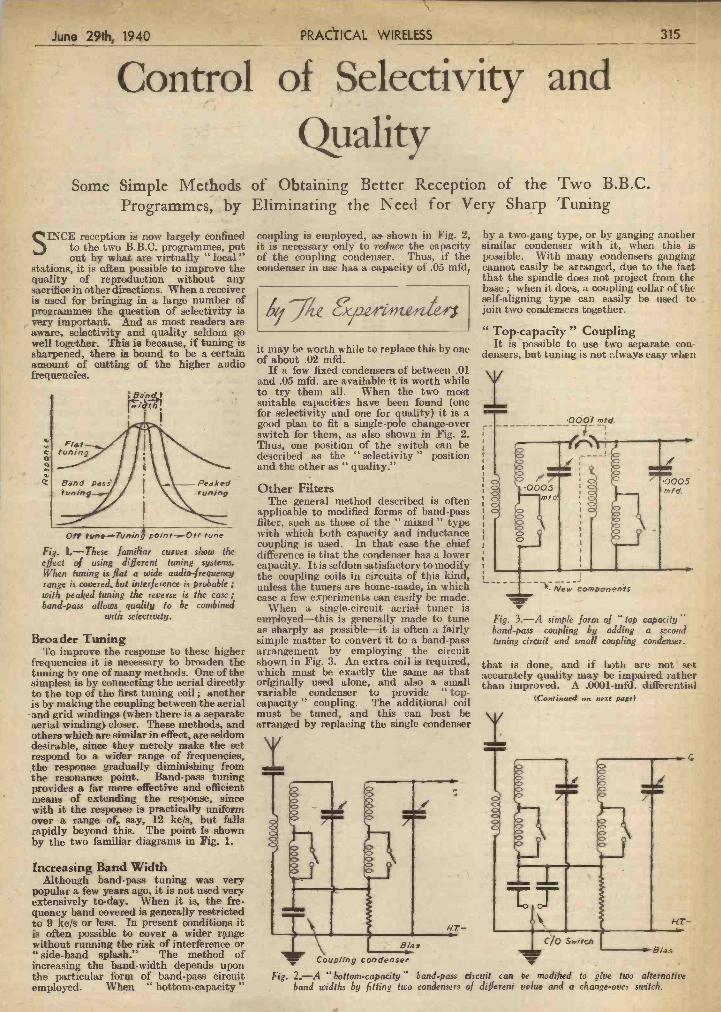
the particular foru of band-pass circuit Fig. 2..-A "bottom-capacity" band-pass circuit can 'e modified to give Iwo alternative employed. Whn "bottom-capacity" band widths by fitting two condensers of different veiue arid a change-over switch.
with selectívily.
Broader Tuning To improve the response to these higher
frequencies it is necessary to broaden the tuning by one of many methods. One of the simplest is by connecting the aerial directly to the top of the first tuning coil; another is by making the coupling between the aerial
-and grid windings (when there is a separate aerial winding closer. These methods, and others which are similar in effect, are seldom desirable, since they merely make the set respond to a wider range of frequencies, the response gradually diminishing from the resonance point. Band-pass tuning provides a far more effective and efficient means of extending the response, since with it the response is practically wsifor,n over a range of, say, 12 kc/s, but falls rapidly beyond this. The point is shown by the two familiar diagrams in Fig. 1.
Increasing Band Width Although band-pass tuning was very
popular a few years ago, it is not used very extensively to-day. When it is, the fre- quency band covered is generally restricted to 9 kc/s or less. In present conditions it is often possible to cover a wider rnge without running the risk of interference or "side-band splash." The method of increasinu the band-width depends upon
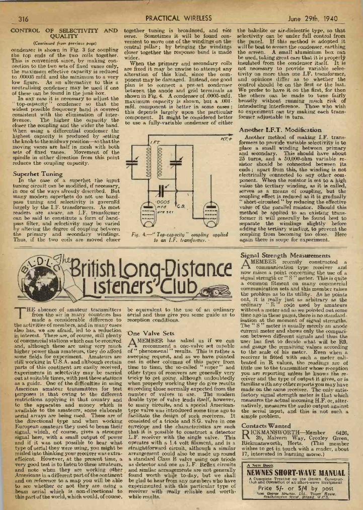
employed-thisis generally made to tune as sharply as possible-it is often a fairly simple matter to convert it to a band-pass arrangement by employing the Circuit shown in Fig. 3. An extra coil is required, which must be exactly the same as that originally used alone, and also a small variable condenser to provide "top- capacity" coupling. The additional coil must be tuned, and this can best be arranged by replacing the single condenser
I
Fig. 3.-A simple form 01 top capacity' bond-pas., coupling b adding - a second tuning circuit and small coupling condenser. -
that is done, and if both are not set accurately quality may be impaired rather than improved. A .0001-mfd. differential
(Continoed on next pae)
stations, it isoften possible to improve the quality of reproduction without any sacrifice in other directions. When a receiver is used for bringing in a large number of programmes the question of selectivity is
, very important. And as most readers are aware, selectivity and quality seldom go well together. This is because, if tuning is sharpened, there is bound to be a certain amount of cutting of the higher audio frequencies.
F/a,
thmncf
_::-:IJ \ç__Pesked
'ufling
O? n Tvrnn& poles r-,()t ,cine
Fig. 1.-These familiar curves show the effect 'of using different tuning systems. Whets tuning is flat a wide audio-frequency range is covered but interference is probable wit/i peaked tuning the reverse is the case; band-pass allows quolüy i'o be combined
condenser in use has a capacity of .05 mfd,
47ÁeaezeitH it may be worth while to replace this by one of about .02 mfd.
If a few fixed condensers of between .01 and .05 mfd. are available it is worth while to try them all. When the two most suitable capacities have been found (one for selectivity and one for quality) it is a good plan to fit a single-pole change-over switch for them, as also shown in Fig. 2. Thus, one position of the switch can be described as the "selectivity " position and tise other as "quality.?'
Other Filters The general method described is often
applicable to modified forms of band-pass filter, such as those of the "mixed" type with which both capacity and inductance coupling is used. in that case the chief difference is that the condenser has a lower capacity. It is seldom satisfactory to modify the coupling coils in circuits of this kind, unless the tuners are home-made, in which case a few experiments can easily be made.
When a single-circuit aeriab tuner is
cannot easily be arranged, due to the fiLet that the spindle does not project from the base; when it does, a coupling collar of the self-aligning type can easily be used te> join two condensers together.
"Top-capacity" Coupling It is possible to uso two separate con-
densers, but tun ng is not Iways easy when
I o6oi mtd.
V
0005 s' Cd.
- Quality
Some Simple Methods of Obtainmg Better Reception of the Two B.B.C. *
Programmes, by Eliminating the Need for Very Sharp Tuning
S INCE reception is now largely confined coupling is employed, as- shown in Fig. 2, by a two-gang type, or by gauging another
to the two B.B.C. programmes, put it is necessary only to reduce the capacity similar condenser with it, when this is out by what are virtually "local" of the coupling condenser. Thus, if the possible. With many condensers ganging
June 29th, 1940 PRÁC1IICAL 'WIRELESS 315
of ;Selectivity' and '
PDF compression, OCR, web optimization using a watermarked evaluation copy of CVISION PDFCompressorPDF compression, OCR, web optimization using a watermarked evaluation copy of CVISION PDFCompressor
purposes is that owing to the different restrictions applying in that country and to the apparatus and money which is available to the amateurs, some elaborate aerial arrays are being used. These are of the directional type and when working European amateurs they used to beam their signal, w hich, of course, gives a stronger signal here, with a small output of power and if it was not possible to hear what type of aerial they were using, you might be misled into thinking your receiver was extra- eflicient. However, at the present time, a very good test is to listen to these amateurs, and note when they are working other Americans in a different part of the continent and on reference to a map you will be able to sec whether or not they are using a beam aerial which is non-directional to this part of the world, which would, of course,
number of valves in use. The modern double type of valve lends itself, however, to many circuits, and a special American- type valve was introduced some time ago to facilitste the design of such receivers. It consisted of a triode and SG, valve in one envelope and the characteristics are such that it is possible to construct a detector L.F. receiver with the single valve. This operates with a 1.4 volt filament, and is a straightforward circuit, although a similar arrangement could also be made up round a standard Class B valve using one triode as detector and one as L.F. Reflex circuits and similar arrangements are not generally found worth while to-day, but we shall be glad to hear from any members who have experimented with this particular type of receiver with really reliable and worth- while results.
factory signal strength meter is thai which meaáures the actual incoming H.F. or, alter- natively, measures the audio output against the aerial input, and this is not such a simple problem.
Contacts Wanted RICKMANSWORTH-Member M26,
39, Malvern Way, Croxley Gi-een, Rickinansworth, Herts. (This member wishes to get in touch with u. reader, about 17, interested in learning morse.)
ft. Sew Book
NEWNES SHORT-WAVE MANUAL A Complete Treatle on the Design, Contruc- tan and Operation 01 ail Short-wave Equipment.
- Price 5/- or 5/4 by post fron, GeorQe Newnos. Lid.. l'ower Hss.
NoVLhom pion .Çtr'et, Strand. W.C.2.
THE absence of amateur transmitters from the air in many countries has made a considerable difference to
the activities of members, and in many cases also has, we are afraid, led to a reduction in interest. There are, of course, still plenty of commercial stations which can be received and, although these are using very much higher power than amateurs, they do afford sorne fields for experiment. Amateurs are still working in U.S.A. and although certain parts of this continent are easily received, experiments in selectivity may be carried out at suitable times, with just these stations as a guide. One of the difficulties in using American amateur transmitters for test
be equivalent to the use of an ordinary aerial and thus give you some guide as to reception conditions.
One Valve Sets AMEMBER has asked us if we can
recommend a one-valve set capable of" phenomenal" results. This is iather a sweeping request, and as we have pointed out in other columns of this paper from time to time, the so-called "super" and other types of receivers are generally very tricky to cet going, although undoubtedly when properly working they do give results exceeding those normally expected Irorn the
ordinary "R" code used by amateurs without a meter and as wo powted out some time ago in these pages, there is no standard- isation at the moment of signal strengths. The " s,, meter is usually merely an anode current meter and shows only the compari- son between different signals and thus the user has first to decide what will be R9, and gauge the remaining values according to the seule of his meter. Even when a receiver is fitted with such a meter cali- brated in R values, the readings are of little use to the transmitter whose reception you are reporting unless he knows the re- ceiver and the type of output it gives, or is familiar with any otherruports you may have made on the same receiver. The only satis-
readers are aware, an LF. transformer former it will generally be found best to can be said to constitute a form of band- method be applied to an existing trans- i
separate the windings slightly before i pass filter, and selectivity may be varied by altering the degree of coupling between adding the tertiary winding, to prèvent the I
the primary and secondary windings. Fig. 4.-" Top-capacity" coupling applied coupling from becoming too olose. Here j Thus, if tise two coils are moved closer to an 1.F. transformer. . again there is scope for experiment. I
C
ritish LoriaPìsta rice I istcncr'CIub
Signal Strength Measurements AMEMBER recently constructed a
communication type receiver and now raises a point concerning the use of a signal strength or " s,, meter, This is quite a common fitment on many commercial communication sets and this member raises the problem as toits utility. As he points out, it is really just as arbitrary as the
- When using a differential condenser the highest capacity is produced by setting the knob to the midway position-so that the moving vanes are half in mesh with both sets of fixed vanes. Movement of the spindle iii either direction from this point reduces the coupling capacity.
Superhet Tuning In the case of a superhet the input
tuning circuit can be modified, if necessary, in one of the ways already described. But many modern superhets do not use band- pass tuning and selectivity is governFd largely by the IF. transformers. As most
Another I.F.T. Modification Another method of making IF. trans-
formers to provide variable selectivity is to place a small winding between primary and secondary. This should have about 25 turns, and a 50,000-ohm variable re- sistor should be cohnected between its ends; apart from this, the winding is not electrically connected to any other com- ponent. When the resistor is set to a high value the tertiary winding, as it is called, serves as a means of coupling, but the coupling effect is reduced as it is gradually ' short-circuited" by reducing the effective value of the parallel resistor. Should this
316 PRACTICAL WIRELESS June 29th; 1940
CONTROL OF SELECTIVITY AND QUALITY
(con:rued from pre1io, page)
condenser is shown in Fig. 3 for coupling the top ends of the two coils together. This is convenient since, by making con- nection to the two sets of fixed vanes only, the maximum effective capacity is reduced to .00005 mfd. and the niinimum to a very low figure. As an alternative to this a neutralising condenser may be used if one of these can be found in the junk box.
In any case it is necessary to adjust the "top-capacity" condenser so that the widest possible frequency band is covered consistent with the elimination of jilter- ference. The higher the capacity the closer the counlina and the wider the band.
together tuning is broadened, and tice versa. Sometimes it will be found con- venient to move one of the windings on the central pillar; by bringing the windings closer together the response band is made wider.
When the primary and secondary coils are fixed it may be unwise to attempt any alteration of this kind, since the com- ponent may be damaged. Instead, one good plan is to connect a pce-set condenser between the anode and grid terminals as shown in Fig. 4. A condenser of .0005-mid. maximum capacity is shown, but a .001- mfd. component is better in some cases; this depends largely upon the particular component. It might be considered better to use a fully-variable condenser of either
the bakelite or air-dielectric type, so that selectivity can be under full control from the panel. If this method is adopted it will be best to screen the condenser. earthing the screen. A small aluminium box car he used, taking great care that it is properl' insulated from the condenser itself. It is not necessary to provide variable selec- tivity on more than one I.F. transformer, and opinions differ as to whether the control should be on the first or the last. We prefer to have it on the first, for then the others can be made to tune fairly broadly without running much risk of introducing interference. Those who wish to experiment can try making each trans- former adjustable in turn.
PDF compression, OCR, web optimization using a watermarked evaluation copy of CVISION PDFCompressorPDF compression, OCR, web optimization using a watermarked evaluation copy of CVISION PDFCompressor

and thus simplifies this part of the circuit. Next I had to use a signal level or output meter. Without this all guesses were right out, but by using this and adjusting for volume as the sound came along I was able to control matters so as always to avoid overloadmg and also to keep up the level for good cutting. By the usual attention to L.F. circuits and components I have now got a recorder which I am proud of.- T. WARREN (Richmond).
r-
Washer
An anti-vibratory chassis suspension device.
4d. - -. - . - Every Thursday
Priictical Mechanics The only English Journal of its type. It deals with every branch of Science, Mechanics. Invention, Model-making, ChemIstry, Astronomy, Photography.
con(ienser m question. When testing a disconnected mains set
in which large smoothing condensers are used, it is very advisable to short-circuit such components before interfering with any of the wiring, otherwise there wifi be the possibility of a nasty shock being obtained by the charge held by the condenser.-E. BOLTON (Derby).
Home-recording AF]IER making several poor attempts
at home-recording I have at last succeeded in making a record indistinguish- able from a commercial product. I have found several essential features which I now give for the benefit of others who may have proved unsuccessful in their attempts. I scrapped a pentode output stage, as I found that one main difficulty was matching the cutting head to the output stage. A triode valve is not so critical for matching
tension on the wire before An easily conirived circuit lester. winding ensured that the turns "stayed put," and the shield was then carefully inserted between the two coils with perfect results.-P. RAKS (Gloucester).
A Chassis Suspension Device FOR this simple anti-vibratory chassis
suspension device the parts required are 12 nuts and bolts, four washers, and a piece of rubber from an old car inner tube. It will be seen froni the sketch that
Cflossis fixing boit
-Wsfle, -1-------Puòber disc -
Chassis
Fixing ar cabinet
supply by using the meter alone. Ordinary tests for continuity can be carried out with this simple combination quickly and effectively.-L. WINOROVE (Pinner).
NEWNES' PRACTICAL JOURNALS Practical Engineering The weekly Journal for those engaged in all branches of the Engineéring
and kindred industries.
A simple dodge for clamping wire under terminals.
gets loose and jams the terminal head before it is properly screwed down. To avoid this I filed a groove in the terminal 8hank, as shown in the sketch, and after twisting the flex wire I placed it in the groove and screwed down the head. Instead of being pushed out, the wire is just pressed into the groove and held fast.-J. T. WHITItLEY (Northampton)
Fixéd Condenser Tips WHEN it is required to ascertain the
capacity of a condenser of a fairly small value, a simple method is to connect it across one of your tuning condensers and note the reduction necessary to tune-in a known station. This differenc will indi- cate, after a little experience with this method, the capacity which the fixed condenser bears in relation to the tuning
SPECIAL NOTICE All hints must be accompanied by the
! coupon cut from page 328.
A Static Screen IRECENTLY wished to fit a Faraday
or static screen between an aerial and grid cc il, but could not make a suitable arrangment. The following idea, however, enabled me to make a screen which really reduces static on my communications receiver, and is easy to wind. Over a solid former of a diameter suitable to fit be- tween primary and secondary I laid a thin strip of copper foil. Across this I wound a coil of bare, thin tinned copper wire. When com- pleted, solder was run across the turns where they crossed the coil, and then the turns were all cut through just above the foil. A slight
stout rubber band is used to hold them together, as shown in thc accompanying sketch. The positive terminal of the meter is connected by means of a crocodile clip and a piece of flex to the positive socket of the battery, and a flex lead is plugged into the other end of the battery. This simple tester comes in handy for checking a suspected short circuit in the high- tension winding. It is much better to dis- connect the H.T. and test with the meter in series with the small battery than to try to locate the leakage of the HT.
Fixing Wire Under Terminals I USUALLY find, when fixing flex w1ire I under terminals that it is either squeezed out of the sides, or elsea strand somehow
E THAT DODGE OF YOURS J
Every Reade, of "PRACTICAL WIRE. LESS" must have originated somelittle dodge which would interest other readers. Wi» not pais it on to us? We pay Li-10-O for the best hint submitted, and for every other item published on this page we will pay half-a.
¡ guinea. Turn that idea of yours to account b sending it in to us addressed to the Editor
PRACTICALWIRELESS,"GeorgeNewnes Ltd., Tower House, Southampton Street Strand, W.C.2. Put your name and.address on every item. Please note that every notloa
¡ sent in must be original. Mark envelope, I"Practical Hints," DO NOT enclose Queries with your hints.
the bolt which is fixed to the cabinet supports the chassis by contact with the rubber disc only. The chassis, therefore, is hung on the rubber discs, one in each corner of the chassis.-J. RATCLIFFE (Yatesbury).
A Simple Circuit Tester MANY amateurs use a watch-pattern
voltmeter for checking their accu- mulators and dry batteries, and such a meter can be made into a handy tester for tracing faults and checking over the wiring -
of a new set. The voltmeter is simply laid on the side of a grid-bias battery, and a
June 29th, 1940 PRACTICAL WIRELESS
tikcdì]I lfttitini its
317
.1
PDF compression, OCR, web optimization using a watermarked evaluation copy of CVISION PDFCompressorPDF compression, OCR, web optimization using a watermarked evaluation copy of CVISION PDFCompressor

IN order to increase the adjacent channel ¡ selectivity of a band-pass filter it is
known to employ low - resistance channel frequencies. Such circuits are, however, liable to prove costly in view of the high-efficiency conductances which have to be used, and consequently the possi- bilities of feedback to reduce the losses of less costly components are worthy of examination.
This subject has recently been, under review in the R.C.A. Laboratories, and the following is an account of some of the circuits used and the results obtained.
Broadly considered, the networks of Figs. i and 3 include two acceptor circuits, C1L1 and C4L4, tuned to the centre of th desired frequency band, and two rejector circuits, C2L2 and C3L3 (Fig. 1), tuned respectively on the opposite sides of the
of the resistor and maintaining a normal voltage of about -3 volts on the-feedback amplifier cathodes.
The cathode lead resistor 20-21, for example, has a stabilising influence in two ways.. First, any change in the plate voltage or mutual conductance of the feed- back valve results in a compensating change
current is used for regeneration through the tickler L5 or L6.
If the mutual conductance of the valve should decrease, a smaller voltage will appear on the cathode. Hence the differ- ence between grid and cathode voltages is greater, giving a larger input voltage to the valve. Thus it can be seen that the varia- tion in plate current is a very much smaller percentage than the variation in valve characteristic. Thus the cathode resistor is the means of stabil ising the amplification of the valve, and such amplification is then used as a means of applying regeneration to the rejector circuit. While a fixed coupling is shown between the plate and grid coils, and regeneration is adjusted to a critical value by adjusting the cathode resistor section 21 and 26, the same result could be obtained with a fixed cathode resistor and a variable tickler adjustment.
I 318 PRACTICAL W1RELES
'Selective Band-pass Filter A Description of Two Interesting Circuits
June 29th, 1940
frequency voltage is applied to the grid, a voltage appears upon the cathode of the same phase, and almost equal amplitude. The true input to the valve is the difference betweén the grid and cathode voltages, and a radio frequency plate. current flows, due to this difference voltage. This plate
regenerative effect is stabilised by the ficance here.) The top curve is assumed to cathode lead resistors 20-21 and 25-26. The Fig. 5.-A series of Fig. 4-Rejection be the desired one. The other curves are lower terminals of these stabiising resistors curves representing the, frequency curve.- obtained when one or more circuit constants are subjected to a negative potential such shapes of band - pass have inaccurate values as indicated on as - 32 volts for neutralising the D.C. drop characteristics. the figure. -
pass band. As indicated by the curve of - Fig. 2, this well-known circuit gives a flat
top or three slight peaks with steep sides in the pass band part of the frequency. amplitude characteristic. With high-loss reactors or with a narrow pass band, the shoulders of this characteristic tend to droop. Regeneration of the rejector circuits C2L3 and C3L3 functions to máintain the desired flat pass band characteristic irres- pective of the reactor losses and the pass band width.
The network of Fig. i includes an electron discharge amplifier 10 which is provided with input terminals 11-12 and with output termi.e- 13.14 coupled through reactor-
.---capaeitor units C1L1 and C4L4 to the input terminals 15-16 of an amplifier 17. A resistor R1 of the order of 100,000 ohms may be connected in shunt to the reactor L1 for reducing the centre peak of the curve of Fig. 2 to about the same height as the other two peaks, and a resistor R, which may be smaller than the resistor R1, may be connected in shunt to the reactor L4.
Interposed between the acceptor or coupling units C1L1 and C4L4, and con- nected in shunt to the main signal channel
- are the low-frequency ifiter or rejector C2L4 and the high-frequency filter or rejector C3L5. Regeneration of the low- frequency rejector G2L5 is effected by means including an amplifier 19 provided (1) with an input circuit including a cathode-lead resistor 20-21 and a grid-leak resistor 22 connected in shunt to the capacitor G2
and (2) with an output circuit including the resistor 20-21, a suitable plate voltage source añd a feedback coil L5 which is inductve1y coupled to the reactor L2.
Regeneration of the high-frequency rejector C3L3 is likewise effected by means including an amplifier 23 having in its input circuit a cathode lead resistor 25-26 and a grid-leak resistor 24 which is connected in shunt to the capacitor C3, and in its output circuit the resistor 25-26, a plate voltage source and a feedback coil L0 inductively coupled to the reactor L3.
Tickler Coils It will be noted that regeneration is
effected through the tickler coils L5 and L6, in the usual manner, except that the
Fig. I (Above).-A filter stage network, incorporating shunt
rejector circuits.
Fig. 2.-Frequency amplitude characteristic curve.
in the grid bias potential of the valve and, as a result, the valve mutual inductance varies but slightly. In addition, this small change in the effective valve characteristic is further reduced by the action of the resistor at radio frequency. When a radio-
'E ----$: -
o
A cj '' Fig.3(Above)-A modi/lcd network including a shunt
circuit.
-
p,ewcc -
Modified System The modified network of Fig. 3 differs
from that of Fig. 1 in that the two shunt rejector circuits C2L.2 and Ci3Ls are replaced by a shunt circuit which includes a capacitor C7 and a reactor L7 connected in series with the parallel connected capacitor C8 and reactor L5. In this modification, the parallel
- resonant circuit is regenerated through means including a single amplifier 27, a cathode Lead resistor 28, and the tickler coil L5 which is inductively coupled to the reactor L8.
When the effective series resistance of C5L8 is slightly negative, -the negative resistance component of this parallel resonant circuit is as indicated by the curve of Fig. 4. At the rejection frequencies, C7L, C8 and L8 form a series resonant com- bination and the effective series negative resistance of (1)8 L8 should equal the resist- ance of C7L7. Oscillation does not occur because of the grid and plate coilresistances. In the pass band, the entire rejector circuit L1-C1-L2-Ct2 has a negative effective resist- ance, but suitable adjustment of the grid and plate circuit losses results in a fiat pass band. -
Lining úp the Rejectors -
In lining up a single stage ifiter such as that of Fig. 1, a signal generator is con- nected to the grid of the amplifier valve and a valve voltmeter is connected to the output of the filter. The first operation is to line up the rejectors for maximum attenuation at the rejection frequencies. This involves adjusting both tuning and regeneration for maximum attenuation. The two acceptor circuits L1C1 and L2G2 are then tuned for maximum response in the centre of the pass band. Alignment may be - found easier if less than optimum damping is used for this preliminary tuning adjust- ment. A head and shoulders curve will then be obtained in the pass batid. The steps involved in correcting this to the desired shape are indicated in Fig. 5.
In this figure, a series of curves are plotted. Each curve represents a possible shape of the pass band characteristic. (The relative height of one curve to another is of no signi-
PDF compression, OCR, web optimization using a watermarked evaluation copy of CVISION PDFCompressorPDF compression, OCR, web optimization using a watermarked evaluation copy of CVISION PDFCompressor

jn1ve. ad smoothing condensers. before new condenser is the obvious cure. (Contitued o next pase.)
culated from Ohm's Law and checked against the normal current taken by the valves used in the receiver. A much higher current would most likely indicate a condenser breakdown in an earlier stage of the set.
If, as a result of disconnecting one of the smoothrng condensers, the voltage becomes normal, a loud hum will become audible, and it may not even then be possible to get the receiver to. work at all. In such a case, the introduction of a new smoothing condenser will remove the hum and the set will work normally.
Mains Receivers.. In the case of mains receivers, it always
nava to make thorough tests of the rectifier
JT -T1 For example, if the volts drop across the
resistance R (10,000 ohms) is 150 volts, it is obvious that the current flowing through the résistance is 15 mA. Supposing that the normal screen current of the valve with 100 volts applied is only 6 mA, it is quite probable that the excess current is caused by a leaky decoupling condenser C, and this shoiild be disconnected. 1f the current resumes normal proportions, a
receiver. Anode volts were found to be within a few per cent. of normal, and the cathode volts were then measured.
Bias for the output valve was derived from a potentiometer across the loudspeaker field winding in the H.T. negative lead, and n voltmeter between point "A," and the chassis, gave a negative reading. On connecting the meter between point "B" and chassis, i.e., on the other side of the
thought as to the probable cause of. the complaint. It will always repay you.
For routine testing a good A.C./D.C. test set is essential. Set about the job methodically, and measure anóde and screen voltages first, commencing with the rectifier valves.
Measure the H.T. voltage at the point X (Fig. 1). Low volts will indicate: (I) a faulty rectifier; (2) a faulty mains transformer; or (3) a heavy current draiñ on the rectifier due to excessive leakage or breakdown of a condenser.
Measure the rectifier anode voltage (A.C.) between "M" and chassis, and "N" and chassis, if the first test has shown low volts. Disconnect the smooth- ing condenser at "X" and measure volts between "X" and chassis. If voltage is O.K., reconnect condenser and disconnect the other smoothing condenser at point "Y." If volts are O.K. reconnect and measure volts drop across the speaker field. Knowing the resistance of the field, the current flowing can quickly be cal-
Now proceed to measure the- anode and screen voltages at AI, A2, A3, A4, A5, G!, 02 andG3, commencing with the output valve. Also, measure the voltage drop across each decoupling resistance and, from Ohm's Law, calculate the current passed, and thence check up the anode and screen consumption of the valves against the valve manufacturers' published data and curves.
i
to a hasty conclusion. If a wrong reading is obtained, consider the probable cause of the fault and proceed systematically.
An example of the use of deduction is shown in Fig. 2, which is the skeleton circuit of the L.F. portion of a commercial radiogram. The fault was distortion and low volume on both radio and gramophone, and this meant that the fault, or at least a fault, existed in the L.F. side of the
Fig. 2.-Output stages of a re- ceiver lo illustrate tile use of deduc- lion from meier
tests.
side operate from a pick-up? Is a faint near a valve and has, therefore, been sub- expect, however, to get your readings to hum present? Spend a few moments' jected to undue heat treatment. agree exactly with the published data on
the valves being used. They should be
Fig. 1.-Skeleton circuit reasonably accurate, however, say between ± 10 per cent. of normal.
showing points ai which tesis should be made. " No Volts "
In the case of "no volts," the obvious
L544 thing is to work back to the main HT. line until a voltage reading is obtained. If, for example, volts are found on one
of a resistance and not on the other, remove the resistance and test it. If tIse
N resistance appears in order or is even replaced by another and a 'no volts" reading is still obtained, it is probable that the decoupling condenser is faulty and short-circuiting the H.T. supply at this point. The decoupling resistance would prevent a full short-circuit on the main H.T. supply, but it is quite probable that the resistance would become very hot.
__________ - During these voltage tests, don't jump
THE object of these notes is to give hints which will enable a set which has developed a "usual" type of
fault, e.g., valve failure, to be serviced in as quick a time as it takes to read this article, and certainly quicker than it takes to write it.
The first thing to do when confronted with a receiver for service is to endeavour to diagnose the complaint. If the receiver is "dead" to radio signals, will the L.F.
to be Rapidly Serviced
proceeding any further. Without wishing to indicate anything detrimental against electrolytic condensers (they are. really excellent when properly used), it is interest- ing to note that four out of the last six sets I have serviced have had smoothing condenser breakdowns. Usually it has been found that the condenser has been worked right up to its maximum voltage, and in some cases over, and has either been totally enclosed or else placed too
The next thing is to measure the bias across the cathode resistances Cl, C2, C3 añd C4, and from these values can be calculated, again from Ohm's Law, the total current taken by each valve.
You should now have enough data to check the operation of all the valves in the receiver, and their associated corn- ponents, and in all probability one of the tests will have cleared the fault by showing "no volts" or "heavy current." Don't
June 29th, 1940 - PRACTICAL WIRELESS 319
QUICK-FIRE SERVICING Practical Hints whicli Will Enable a Set that has Developed Valve Failures
PDF compression, OCR, web optimization using a watermarked evaluation copy of CVISION PDFCompressorPDF compression, OCR, web optimization using a watermarked evaluation copy of CVISION PDFCompressor

Combined Tuning und Wave-change Control
A Method of Controlling Both These Operations with a Single Knob
MANY proposals have heretofore been made for improvements in the control of radio receivers. It has
already been proposed, for example, to reduce the number of controls by making one control perform two or more opera- tions; or to reduce the space occupied by arranging two or more controls concentric- ally.
The accompanying sketch shows à simple 'arrangement whereby both the tuning
indicator and the wave-change switch can be actuated by means of a single control knob. The control is shown in section, and the wave-change switch i is provided with a spindle 2 arranged in a bearing 3 which is secured to the chassis 4. The end of the spindle 2 is provided with a circumferential groove 5 for a purpose which will be described later. A hollow control spindle 6 le rotatably mounted on the wave-change switch spindle 2, as shown, and is provided with a control knob 7. The spindle 6 is held to the shaft 2 by means of a pin 8 which projects into the groove 5, and thus allows a limited amount of axial movement between the two shafts. The
end of the control spindle remote from the knob is provided with one member 9 of a clutch, and the other member 10 of the clutch is rigidly secured to the wave-change switch spindle 2. The members 9, 10 are biased apart by a spring 11. The hollow
fl ?-'
Section of the single-knob con- ¿'iay'#F&L ¡rol device de-
7 J scribed in the text.
control 6 is provided with a circumferential recess 12 round which a cord from a pulley associated with the tuning condenser may be wrapped. Operation
In operation, rotation of the control knob 7 will cause the hollow spindle 6 to rotate round the wave-change spindle 2 and operate the tuning indicator through a cord drive. When it is desired to change the wave-band the control knob 7 is dis- placed axially to bring the clutch members together, and then rotated so that both the wave-change switch and the tuning indi- cator are moved together; as soon as the correct wave-band has been found the axial pressure upon the control should be removed so that a farther rotation causes only the tuning indicator to operate. It is Inadvisable to secure the driving cord positively to the hollow spindle 6 so as to avoid unnecessary strain upon the cord if the control should be manipulated for changing the wave-band switch when the tuning indicator is in a limiting position.
PRACTICAL WIRELESS SERVICE MANUAL
By F J. CAMM. Yrom oil Book,,Iiers 6/- DeL, or by posi 6/6 direot from tbe Pubjiebep.. Georg, Nowoei. Ltd. (Book Dept.). To,.ez House. SooUiompton St., Stesod. LoodOo. W.C.i.
as well as the grid circuits. Referring again to Fig. 2, the pick-up or oscill&tor should be connected to each of the points W, X, Y, Z in turn through a I mfd. condenser. In the case referred to above, the fault would have been immediately located at the point W, but had the primary of the transformer been connected to chassis instead of to the secondary and ILT. negative, point "W" would have been shown up O.K. and the fault not located until the pick-up was connected to the primary side of the L.P. transformer.,
The oscillator voltage should remain fairly constant over the vhole of the wave- band, although it may vary for different wavebands. For instance, on SW. bands, the oscillator anode voltage is often increased. The quickest method of check- ing an oscillator is toinsertamilliamineter in series with the oscillator anode, between the voltage dropping resistance and the main ILT. line, and note the reading. Short-circuit the oscillator tuning con- denser, or connect a large fixed capacity condenser across it. A change of oscillator
consumption of the receiver can be quickly calculated from Ohm's Law.
4. If the H.T. supply appears to be at fault, examine the smoothing con- densers first. Disconnect each one of them in turn until a voltage reading is obtained. Ignore the increased hum for the time being. It will be immediately reduced as soon as the smoothing condensers are reconnected, or new ones substituted.
valve to drop. We will presume that after taking these
readings, all voltages and currents have been found to be reasonably normal and that the fault cannot be located.
Interjecting Signals The next step is to inject a modulated
L.F, signal into the L.F. stages, commenc- ing again with the output valve, and work- ing back to the grid of the first L.F. valve. A pick-up will do for this. Provided that a condenser is fitted in series with the pick- up or oscillator leads, it is quite per- missible to inject th signal into the anode
main HT. supply Never connect it between anode and the I.F. transformer.)
Keep the aerial and earth connected to the receiver and rotate the tuning con- denser very slowly. As a signal is tuned in, the current should decrease if the H.F., I.F., detector and A.V.C. circuits are in order.
In a superhet receiver the oscillator section of the frequency changer is quite a frequent source of trouble. If the oscil- lator fails, no I.F. signal will be reproduced, but in some cases the oscillator may only fail on certain wavebands, or parts of a waveband. -
1. Always make sure tbat the aerial has not been inadvertently dis- connected.
2. In the ease of a battery receiver, make sure that none of the battery leads have been pulled out or inserted in the wrong positions.
3. The quickest way to estimate whether a valve is likely to be the cause of the trouble, especially where read- ings cannot be obtained without removing the set from its cabinet, is to measure the voltage drop across the speaker field. These terminals are easi1y accessible and the current
coupling condenser C was leaky, and allow- ing a positive H.T voltage to appear on the grid of the output valve. The insertion of a milliammeter in the circuit in series with condenser C showed that nearly 10 mA was flowing through the condenser. On examining the condenser it was found to be an electrolytic variety, and it was learnt that this had been put in when the set was serviced on a previous occasion. Removal of the condenser and its substi- tution by a paper one, cured the trouble, although the positive voltage on the grid had caused the emission of the output
to long waves and rotate the timing condenser to maximum capacity.
There are two fairly common faults which will not be located by simple voltage tests and which can be found without the use of an oscillator. One is a faulty diode or A.V.C. circuit, and the other is failure of the frequency valve to oscillate.
The simplest way to test the diode and A.V.C. circuit is to connect a milliam meter in the anode lead of one of the controlled valves (keep the meter leads a short as possible and always connect the meter between the decoupling resistance and the
change in current consumption occurs at any point or points, indicating that the valve is going in and out of oscillation at this point. Don't confuse this with a gradual change, for no oscillator will give a constant reading over the whole of all the wavebands.
Final Hints Here are a few hints, which are the
result of actual experience, and which may help the reader when called in to service a receiver:
320 PRACTICAL WIRELESS June 29th, 1940
QUICK-FIRE SERVICING (Coni jn,,ed from prePiou, page)
G.B. decoupling resistance, a reading of several volts poßiiive was obtained.
Consideration of the probable cause of the complaint, and ari examination of the theoretical oircuit, suggested that the
If the fault cannot be found in the L.F. portion of the receiver, an HF. or I.F. signal must be injected into each H.F. or IF. stage in turn.
When carrying out any of the above tests, remove the aerial, set the volume control to maximum, switch the receiver
anode current, which may arise or fall depending on the type of oscillator in use, should occur. If ño change occurs, the oscillator is not functioning.
In the case of partial failure, this will be shown up by tuning the set through the various wavebands and noting if a sudden
PDF compression, OCR, web optimization using a watermarked evaluation copy of CVISION PDFCompressorPDF compression, OCR, web optimization using a watermarked evaluation copy of CVISION PDFCompressor

I BENO NEA.E py4q,
so.oEqEo 0M. ,tiqru/
A'(JT e.BOa.T. ¿.00IcNb/r
LL]J p ty4I_.
Fig. 2-Detail, of lop armatore. BuYo qS S/tC
fixing mud- RNQTJE guards), two 2BA bras s
TOP 4ç'nAr,.qE bolts lin. B54R11G5.
' nuts j-'. 24 on each;
five ter- minais,
BAWD 47. seven in. PIGI-7- 4Mf.E w o o d
I I-is'. 3.-Top orma' teatino,
acre U S
a n d a tore piece of
wood for TO ÑPPÎATURE b a se 3
Li ßsR/tp'GS by 4m, by /1 about sin. 4(1/
i_j '
t hick. BEND TM/5 The bell
bobbins 2 PICE5 are best
4.qu/IE bought if an old
the small wood screws. The armatures, bearing supports, and stops are next
E cut to size out ofthestrip and the holes drilled.
Solder the lin, nails to the OL.DPED armatures; as shown in Fig. 2, T4JQ and fit the iron cycle bolts.
-7 Cut the bolts off flush with J- face of nuts and give the
nuts a thin film of solder- this secures them further and
M also prevents them - 4 " sticking" to the
F' Iffih1I "1. magnet cores. Fit f1H!J 3,.." . the 2BA bolts in
4 position and solder
HERE Bend the arma- w'ia the bottom nut
only on each.
tures, stops and 2 ,_!' bearings to ap- proximately the shapes shown in Figs. 3 to 7, then assemble the top
/1EEarmature and IoJ + bearings first. See
that the iron nuts on
HO.E5 a r m a t u rea ßE.PYO are directly
70P 7 opposite the magnet (coil)
5TOP j cores. Fix the terminals
Fig. 4.- Top armai i,re stop. and connect
tip as iii Fig. 8. Before
bottom armature, and effectively locks it
BPYD THI5 7j)7) - 2P,ecES F'II
_i,,...
i;.' j a BOTTOM BEAq/MGS
Fig. 7.-"Deta,l, of botta,,, bearings.
when properly adjusted. This action takes place instantaneously.
On sending a current through coil No. I, the top armature is attracted to core of No. i coil and releases the bottom armature, which fails by its own weight back to its stop.
lt will be seen that only .a momentary current is needed to operate the relay. The operating circuit ja quite distinct and separate from the low-tension circuit of the
- WIRELESS BO.T 04. &ML/T5
9t I
BEMO THuS
$_.,..,,,,,., .._....i Fig. 6.-Batto,,, ormai,,,., tot' and bearing,.
HOLES -
simple construction, the device is the result of considerable experi- ment.
A special feature is that, unlike most other controls, it consumes no current while the set is in use, and gives a positive on-off contact. The action is similar to a G.P.O. line relay and sounder, and compli- cated, unreliable clock actions, etc., are avoided. The parts required are two electric bell bobbins (complete), about 18m. of ¡sin, springy brass strip 1132m, thick, two small iron or steel cycle bolts (as used for
E, & £2 I/RE SERR,Ncrs SC/PPOR77NG THE /7Á'MI/ TI/RES .1 & B.
D,& D2 ,4ovsr/NG SCREWS. X /w CYCLEN/TS Boz rs.
Fig. ¡--Cern plete4 relay showing armature ' aurocted, and relay in c!05d position after No. 2 coil hai bcen momentarily ene ,gised. L. T. circuit is then closed and L.T. current then flows up the bottom armatore Io top armature through
bearings to set.
L c
bell is not to hand. In the latter case two' small iron or steel bolts will serve as cores.
Details of Construction First drill a hole through the base as
shown (Fig. 1), and mount No. 1 coil upright by means of the nut on the core
end. It will be necessary to recess the bottom of base a little so that tIte nut'
j- will be flush. Coil No. 2 is then mounted horizontally on a small piece
T of 3/l6in. wood or ebonite, and is secured to base by a metal strap (cut out of the brass strip), and two of
QN
I'Ls Fig. 5.-Ro:lom ambla,:.
i SOd-DEE
through coil No. 2 the bottom armature is attracted to the core, and in doing so knocks against the top armature and lifts it up. The top armature acts as a kind of latch, and immediately drops back over the
A Useful Device Made from Odds and Ends
AVERY fascinating hobby is the control of various pieces of apparatus by means of distant-
operated switches, and the details given In last week's issue of one reader's attempts in this direction will no doubt arouse a desire to carry out similar schemes in the homes of many experi- menters. Although it is possible to purchase ready-made relays or similar devices, there is much more interest in making up your own apparatus, and the following deta ils °
which were given by us some years t
ß1ç'qss 5recP 1/CL 0//VG CoIL r0BRSE
l811c X 5rop .-8S2 .
2H-. L
ago are taerelore reprinrea loT rnose who wish to make up a similar type
) CO>L N°2
of instrument. Although of very '2' Th,ci< PncKulG (EBONITE OR I'v'OOD)
testing it will be advisable to explain the action of the relay.
How the Relay Operates The relay operates on each coil
separately, the normal position of relay, when not in use, being shown in Fig. 10. It will be seen that both armatures are so balanced that they normally rest on the 'stops." When a current is passed
- /
ß5r1O HERE
1J PvlJ7 (I
:
29th, 1940 PRACTICAL WIRELESS
Home-made Remote Control
321
PDF compression, OCR, web optimization using a watermarked evaluation copy of CVISION PDFCompressorPDF compression, OCR, web optimization using a watermarked evaluation copy of CVISION PDFCompressor

MOST people are familiar with the melodies which ran through that
musical-comedy success of the last war, "The Maid of the Mountains," but how many know anything about its composer, H. Fraser-Simson, who is, in fact, one of the. most versatile and successful of British theatre composels? The life and work of "The Man who Wrote 'The Maid of the Mountains,'" will be the subject of a musical biography to be broadcast in the Home Service programme on June 28th. Compiled by M. Wilison Disher, Gordon-
MeConnel and Gwen Williams, this pro- gramme will give a picture of an exceed- ingly versatile musician who has created not only popular but musicianly scores for musical comedy, revues and ballet. Many listeners will recall Fraser-Simson's settings of the Christopher Robin verses by A. A. Milne.
The singers wifi include Joan Cross, Dennis Noble and Billie Baker, supported by the B.B.C. Theatre Ohoru and Theatre Orchestra, conducted by Stanffird Robinson.
i Film Festival will be a revival of the radio version- of "Babes in Arms," which was regarded at the time as a model in intelligent compression for broadcasting purposes. It will be heard on July ist. Of recent film music scores of this type this is surely one of the most attractive-which is hardly surprising when it is remembered that Richard Rodgers and Lorenz Hart were responsible for it. The haunting "Where or When" and the high-spirited "Good Morning" are regarded as excellent examples of the present trend in popular music, particularly the former.
8'55 S7?tP..d' f FRQPIT5TOP aa. Fi0. 1O.-Showin top armatore in action at the moment of energising N0. ¡ roil. The armatore is clear 4 its stop foe a moment, and this frees the bottom P.CKI1°f G )4"f6T''ilG#( armatore which is shown dropped clear by its own weight. The dotted lines
Fig. 11.-Relay in normal position-note top armature, resting on stop, as alio botlom armature, show the previous position of litt armature.. Top armatore drops bock on to itr No coils ene rgised. stop after being momentarily energised. -
mounted on an oblong switch block, and may be used. Three wires are necessary especially for the purpose is admirable-and may be of different colours or simply, to each point. Both relay and operating try to avoid a heavy loss through the leads marked with panel transfers, but this is, of battery should be as near to the wireless by using large-capacity batteries or, alter- course, optional. Any number of control set as is possible to keep the low-tension natively, one of the smaller types of points, with two pushes at cach point, wiring on the set as short as possible. accumulator.
-I
'tihe Man Wh0 Wrote 'The ... ' 1 Film Festival (4) : "Babes in
;BROADCAST ITEMS Arms" Maid of the Mountains 'T'RE fourth troduetion in the Summer
Two ordinary bell-pushes ,°cisg 0M are used for operating. One
I
Q&Y 5rrev push is used to switch the set off and the other to switch it on The pushes should be
N1? 4RI1ATVP. PIVOTED T I.
AÇ1U5T HERE _LQCK-tyJT3 II ,-r-
or call is used to operate the mechanism there is a risk of such a loss of current in. passing through the long leada that the relay fails to operate. Therefore, obtam a really heavy extension lead-one of the multiple leads sold by Messrs. Bulgin
SOL.oq 5O77O'T f/75 7'Q 4q'MArv1qS
T
armature. - OPERATING TER.
Simple Adjustments -circuO to rciau. A certain amount òf ad-
Figs. 8 and 9.-Showing wiring and
justment will be necessary on both armatures to get smooth working, but this will not be difficult as ______ ________
.Q.vcNruc7 CseCvir they are made of springt SEPÑR.Q7T 70 5Er brass. For operating the o
relay 3 volts will usually i - suffice (or a flashlamp battery), but up to 6 volts 3 can be used, especially if there is a long length of wire to the control pushes.
adapt this control to your own par-
_. ticular receiver, as there are --- so many different arrange- - mente which may be made
up, and these depend, - naturally, on the type of - receiver which is in use and
what form of reproduction is used, i.e., 'phones or loudspeaker.. There is.ono
point which must always be- borne fn mind when fitting up this form of relay, antI that is that the curreht which óperates it has naturally to pass through the extension leads, and when oiüy a very small battery
bottom armature, bearings, t
- LT rwr'i.s be made to through bottom armature along
u ro sr & CC(IMUATO house the top armature (wherein contact), relay if down top armature bearings and I I
SE4T CIC(JIT desired. If out to other L.T. terminal on r'
OM QELJW) properly relay base. To test the relay before using (as is advisable),
adjusted it will be found to
connect temporarily one end of I operate efficiently a battery to terminal 3. Touch without atten- terminal 2 and bottom armature tion. should be attracted as explained. O
WIRE TO 0f course, it is On touching terminal i the top armature should be attracted,
not necossary to
thereby releasing the bottom ______________________________ give any instruc- tinas as to how to
322 PRACTICAL WIRELESS June 29th, 1940
HOME-MADE REMOTE CONTROL WiSE ro ro Finally, see that the (Continued from previous page)
______________________ mø'ved otherwise 1f set which it throws on. and off. fi ___________________
9°/Md relay in.keptli a hori-
The L.T. circuit is from one of the I
uót
tilted, its working will be erratic, A neat wood
two terminals (see Fig. 8) to canine can
PDF compression, OCR, web optimization using a watermarked evaluation copy of CVISION PDFCompressorPDF compression, OCR, web optimization using a watermarked evaluation copy of CVISION PDFCompressor

been shown to depend upon the size and cable, and in Fig. i this is shown as Y. building. The feeder cables are held apart spacing of the conductors comprising it- Here, again, a reducing factor has to be by insulating distance pieces of the appro- see formula on page 240--and when the introduced which changes slightly accord- priate length, and are connected to the proper adjustment of the line is made at ing to the frequency of operation. Calling aerial proper at an exact distance ba&d the radio frequency employed then it will this k1 we have k1 is 0.25 for frequencies on calculations using the three preceding act as a pure resistance joined across the below 3,000 kilocycles; 0.24 for frequencies formuhn.
from Fig. 1, the feeder is made to diverge for a distance Z before the junction is made. This is for the purpose of intro- ducing an exact impedance match between the aerial and the twin wire feeder termi- nation. This ensures a maximum transfer of power, and also eliminates any radiation from the feeders themselves. This match- ing question is an important one, and must be accepted at this stage; further details concerning its working will be dealt with in a subsequent issue.
The transmission line has a certain characteristic surge impedance which has
150,000k metres
where f the frequency of operation is expressed in kilocycles. That is to say, for a 2 metre system the aerial length would be 0.94 metres. If it is desired to express X in feet, then it is only necessary to introduce a simple conversion factor and we have
X 492,000k feet f
The next important dimension concerns the coupling bctween the aerial itself, and the diverging lines of the twin feeder
feeder is nearly 200 times the radius of the wire used for the feeders. That is to say, if No. 6 gauge copper wire was used for the transmission line, then since the radius of this wire is 0.O8in. the distance between the wire centres for the twin run would be approximately 16m.
An Example As an indication to readers of an actual
dipole aerial erection with a Y matched twin wire open feeder, reference can be made to Fig. 2. This shows a dipole secured by an arm at the top of a mast, which in turn is guyed to a high flat roof on the top of a
IT
Peeder to i'ranstormet
Spàc,ng Örs
Fig. 1.-The simple layout of the aerial system described on
this taSe.
proviaing maximum radiation at the wavelength or frequency selected. The first item is naturally the length of the aerial itself, and in this case a small reducing factor k has to be introduced to allow for the fact that the aerial cannot be erected in free space. This factor will vary according to the diameter of the wire employed for the aerial, the factor becoming larger the thinner the wire. In addition, slight changes in k have to be made accord- ing to the frequency employed. For fre- quencies below 3,000 kilocycles, k can be taken as 0.96; between 3,000 and 28,000 as 0.95; and above 28,000 as 0.94. Revert- ing to Fig. 1, therefore, we have the length of the dipole X given by
connection and his given by the formula: Z 45,000 metres
where f is in kilocycles as before 01
= 147,600 feet. f
These simple equations only hokl good for those installations where the charac- teristic impedance of the twin wire feeder line is 600 ohms, but as was mentioned earlier this is the standard worked to in the majority of the Service and commercial installations. If, therefore, this ligure is substituted in the f orniula given on page 240 (June Ist issue), it will be found that the distance between the wires of the twin
suitably adjusting the coil taps at the transmitter.
Proper Matching The aerial is a dipole, etected either
horizontally or vertically a required, and this is fed by a twin-wire open feeder. In the June ist issue, referred to above, it was shown that the maximum current conditions occurred at the centre of the aerial, but feeder connection is not made directly at that point. As will be seen
causing reflectÏons, and so upsetting the efficiency of t h e installation. Under correct working conditions, however, the only loss should be the FR losses, which is quite negligible.
Useful Formula The form of connection between feeder
lines and aerial shown in Fig. i is generally referred to as Y-matching, and if the formuin which follow are used correctly, each installation should be capable of
between 3,000 and 28,000 kilocycles and 0.23 for frequencies above 28,000 kilo- cycles. The length now becomes
y_ i50.(X!0l metres
where f is in kilocycles or y 492,000k1 feet.
The final item now relèrs to the length Z of the diverinu section of the feeder
June 29th, 1940 PRACTICAL WIRELESS
fl t A I
Why working? Further Notes ort Dipole Aerials, by
H. J. BARTON CHAPPLE, B.Sc.
THERE are no doubt many newcomers output of the transmitter's to radio, both in the services and last stage. It will be outside, who are called upon te found in practice that for
work with dipole aerials for the first time. most commercial purposes Furthermore, it is possible that some of the dimensions of the feeder the pre.war transmitting folk who used line are chosen so that it certain types of feeder and aerial sy8tems provides a characteristic did so without thoroughly appreciating impedance of 600 ohms. their real significance when it came to the question of why certain steps were taken. Surges The notes which follow have been prepared When the whole system with the object of clarifying an important is correctly balanced, each point in so far as it applies to a twin.wire of the twin wire feeders is matched impedance feeder system which at an equal but opposite has been found to be very suitable for use potential to the other, and with push-pull transmitters, and s really a in consequence radiation continuation of the data and description from the lines is neutral. furnished in PRAcTIcAL WIEELSS dated ised. If this condition is June ist, pages 239 and 240. The success not achieved, that is, if of this complete aerial system my be said phasing and matching is to depend primarily on certain physical not accomplished, then all dimensions, which must be correct for the the power will not be particular operating frequency allocated delivered to the dipole for the installation. These are shown as aerial for radiation into X, Y and Z in Fig. 1, and when this has space, and the remainder been erected correctly it is only necessary will surge backward and to determine the right load conditions by forward alonr the line
i-
323
Fig. 2.-An actual ex- ample of an aerial and feeder installation based on the points discussed in
(his anide.
PDF compression, OCR, web optimization using a watermarked evaluation copy of CVISION PDFCompressorPDF compression, OCR, web optimization using a watermarked evaluation copy of CVISION PDFCompressor

multiplied by 10, and so on.
be provided so that instead of taking the the Instrument. 0n the other hand, for A Typical Sample meter reading for, say, .5 mA., this may those who have an instrument of 100 ohms represent 50 volts. For the benefit of The following constructional details will or who obtain one of that value, we give new readers, the idea works out as follows: give an idea of the lines to be followed in below a table of the necessary shunt and The meter will have an internal value, making an all-purpose meter, the main series resistances for various current and usually of 50 or 100 ohms. Any meter may be used, but the actual current range 2500
-
'g.2.-Wing should not be greater than i mA. Suppose Diagram. in this that we use a meter with a resistance of am the "wafers" of the switch 3Voit 100 ohms, and connect across it a resistance are shown as though hing
of 100 ohms. This means that if a small is through
That is contact I is actu
voltage applied a circuit so that a current of 1 mA. flows, this will divide and flow equally through the meter and the extra 100 ohms resistance, and accordingly the meter needle will only rise half-way up the scale. If the scale is calibrated, this would mean that the meter would indicate .5 mA., but we suggested that the meter /2a had been connected to a circuit through /6
-1 /16
which lmA. was flowing, and therefore, our meter indication is only half of the true current. In other words, we have
- multiplied the scale by 2 by shunting the meter with a resistance equivalent to the _______ meter resistance. If we shunt the meter '«J W with a resistance of Buch a value that only 7 ______ r
one-tenth of the current flows throùgh 110
the meter and nine-tenths through' the shunt resistance, the meter scale will be
2,500 0--- - O.;=:===.O \
- o
o0
4-'
Test. 3V fO Ieds , Q
Fig. 1.- Theoretical circuit of the 12.-range meter
components inside the, meter case, and choosing these properly, indications may
resistance of 9,900 ohms in series and then connect the two across a 1-volt supply the needle would rise to i on the scale and thus we have obtained our desired range. This may be extended up to any desired voltage range, although if, for instance, we wish the meter to read 1,000 volts, we need not use a resistance of 999,900 ohms, as the percentage error would be so small that we could use a standard component of 1,000,000 ohms with little margin of error on the scale. The use of the meter for measuring resis- tances is carried out in a similar manner, including a small cell inside the instrument so that this. is connected in series when a resistance is being measured, and calibrating our scale in resistance values in ohms, according,to the current flowing. Usually, a home-made meter is arranged to cover only one range of resistance values, external batteries then being added to give multiples of the resistance range as required.
Fig. 3.-The finished instrument in its home-made case.
difference between the average home-made instrument and a commercial meter being in the selection of the appropriate ranges.' Usually, the home-made instrument is provided with plugs and sockets, whereas the commercial instrument has a single control with multi-switch unit for the same purpose, and by adopting this method of construction the use of the meter is greatly simplified, and a more professional finish is obtained. In the samplei Ilustrated, a double-band 12-contact switch was used, this being manufactured by A. B. Metal Products, Ltd., and may he obtained from B.T.S. The meter used was supplied by Premier Supply Stores and has an internal resistance of 60 ohms. We understand, however, that these are no longer available, but many readers may have one of these on hand and wish to make
-- -. A Home-made All-purpose Instrument
-
with Single Switch Control I
OSTreader
ByW. J. DELANEY :
s are now aware that an Voltage Readings all-purpose tester may be made up The above explanation shows how the round a single range milliammeter. meter may be made to read various current It is usual to use a meter with a full-scale ranges merely by switching in suitable deflection of i mA. for this purpose, and shunt resistances. To enable a voltage to increase the current reading various reading to be obta!ned, for which purpose
resistances are shunted across it. To the meter has to be joined in parallel with enable voltages to be read, resistances are the supply or circuit, some form of limiting -s
connected in series with it, and for the resistance must be included, also in series, .3O '-Ni / SOO f
reading of actual resistance values a small so that the total current flowing through Z9... / 'OO voltage is included in series. The basis the meter does not exceed 1 mA. Suppose tj of all these tests is that the meter passes ve wish to make the needle indicate 10 f
a current up to the maximum indicated on volts when it points to I on the scale (that I the meter, and by including' additional is, at full-scale deflection). Ohms Law
gives us the rule that i mA. will flow .
O-/Ma. through a resistance of 10,000 ohms when 10 volts are applied (current equals voltage divided by resistance). Therefore, if our
i meter is loo ohms and we connect a
i
324' PRACTICAL WIRELESS June 29th, 1940
A Twé1ve-rcinge Test-meter
PDF compression, OCR, web optimization using a watermarked evaluation copy of CVISION PDFCompressorPDF compression, OCR, web optimization using a watermarked evaluation copy of CVISION PDFCompressor

series resistances to the two-bank witoh purposes (on the i amp. range), clips had for the different ranges is shown in Fig. 2, to be used to maintain constant contact, 4
and it will be seen that when set to the but this is a point which may be left to the a
"Resistance "range, a batteri' and variable individual constructor. For accuracy, i:.. .
resistance is included In circuit, in addition the series resistances should be specially . to a fixed resistance. These are essential selected and most manufacturers can :
for every- j
::RAflIfl 5VOLTS -:
1AMP----- I rSOVOLTS, : N.E ED
\ ..
j
i,,,
.
The range of pilot - - -. -. lamp holders is un-
250 M A- / 100 V OLTS - equiforquality
- ç. A large variety of j
- different models is
25 M A - -. 250 VO LT s actually stocked, and
- A, B, C, D or E can :
be fixed to any
5 .A e bracket. The selec- -
yu V'.dLl . tion below is repre.
-. - - sentative of our wide
- range.
:1 1MA -10O0 VOLTS - ':.
esiOra -.g radio components, --
:- ....j_._ -
chokes, switches,
I '. ( plugs, etc., particu-
lars of which we shall . - r -
be glad to supply - upon application.
- - If you have not yet
June 29th, 1940
voltage ranges. From these the appro- priate values may be chosen to give any desired range. Incidentally, Premier Radio can supply a ready-wound shunt resistance for a 60-ohm i mA. meter which will give readings of 5mA., 25iuA., 25OmA., and I amp. The wiring of the shunt and
PRACTICAL WIRELESS
At the end of the leads, sockets are soldered, and these are made to take crocodile clips or other methods of obtaining contact at the points of a circuit whieh are to be tested. Alternatively, the Bulgin test: prods may be used. As the meter in ques- tion was intended to be used for charging
TYPE.
325
TI5 dial Indicator mag ¿e cut out and stuck on tite pael. Copies on ari paper may be obtained from this office for 3d.
additions. When a small battery is included in series with the meter, a given range will be provided, but as the battery becomes discharged the reading will vary and thus a scale could not be accurately calibrated. Therefore, if a moderately low-value resistance is included in series, this may be adjusted to compensate for the varying voltage of the battery. In the original instrument this resistance bas a total rating of 1,004) ohms, and it is included on a small bracket inside the box, with a hole at the top through which a small screwdriver may be inserted for a zero setting. The normal spindle is cut down to about )in. in length and is then slotted by means of a thick-bladed hack-
- saw or two blades mounted side by side on a hack-saw frame. The battery used was a standard No. 8 torch cell, a small section of the bottom of the box (home- made) being cut out, and two spring con- tacts being made from the brass strips taken from a disused flashlamp battery. A sliding metal lid was provided with a keyhole and hinged to facilitate replacement when desired: To obtain the zero setting the two test leads are short-circuited, and the screwdriver inserted in the hole and the needle adjusted to read an exact zero. With a 50-ohm meter, a 1,000-ohm variable and a fixed value of 2,500 ohms, the meter scale will read from O to 200,000 ohms.
Test Prods The test leads are ordinary red-and-black
flex connected a shown to indicate correct polarity. This ia most important and must be preserved to avoid damaging the meter.
supply these specially at a slight extra charge. These are incidentally also obtain- able from Premier Radio, guaranteed 2%+.
SHUNT RESISTANCES SERIES RESISTANCES
Multiplying Resistance Factor ¡n Ohms
2 loo 3 50 4 33.33 5 25 6 20 8 14.29
10 11.11 20 5.26 30 3.45 40 2.56 50 2.04 60 1.695 80 1.266
100 1.010 200 0.503 300 0.34 400 0.251 500 0.200 600 0.167 800 0.125
1,000 0.100
Voltage Range
Desired
I Resistance I
in Ohms I
2 volti 1,900 3 ,, I 2,900 5 ,, I 4,900
10 ,, I 9,900 15 ,, I 15,000 20 I 20,000 30 30,000 50 I 50,000
loo I 100,000 150 ,, I 150,000 200 ,, I 200,000 300 ,, I 300,000 500 I 500,000
1,000 ,,
1,000,000
WORKSHOP CALCULATIONS TABLES AND FORMULE
(Second Edition)
By F. J. CAMM
3/6, by post 3/IO from
George Newnes. Ltd. (Book Dept.). Tower House.Soutl,ampton St..Strand. W.C.2
1
had a copy of our I current catalogue,
send now. This con- tains full details of the whol "BULGIN" range.
:1-
A SELECTION M.E.S. Dual Live 6° 28 Bracket. I1.E.S. Springplunger 3°
26 Contact. M.E.S. Double Clip 3°
33 Bracket. M.E.S.Recessed Fix. 30
9 ing Bracket Live.
M.E.S. AsNo.60,side 3F 82 earspinched
- over. 11.E.S. L i vg Fixing 3
61 Bracket. M.E.S. As 27, side 3D
42 ears pinched over.
M.E.S. As 27 less side 3D 45 ears.
M.B.C. As No. 12,ears4° 14 pinched over. I
WI.B.C. Baseboard or 4" 6 chassis fixing. it
S.E.S Baseboard or 4" 81 chassis tlx,ng.
c.E.S. Baseboard or 4° 6 chassis fi,dng.
PLUS I6% WAR. - ,., lNl4.EAbE
-. [ LWAY S. O P E N O:N
i- B U L G:
I N:.
Adsoot. nl A. F. BULGIN & Co. Ltd., BYE PASS ROAD. BARKING. T01. RlPpkway 3474(4
PDF compression, OCR, web optimization using a watermarked evaluation copy of CVISION PDFCompressorPDF compression, OCR, web optimization using a watermarked evaluation copy of CVISION PDFCompressor

midget capable of pocket use. Will two valves give me the desired result and, if so, what types would you advise, especially as I wish to keep batteries to a minimum? I should also like some recommendation as to a suitable circuit for strict portability."- G. F. (N.W.5).
"I recently assembled some parts into a straight four-valve set which, although H
works well on mike and pick-up, gives a bad howl on radio. I made several modifi- cations to the layout and screening, but I find that the output is low on the mike circuit and the howl cannot be removed.
uae a pre-set or small variable condenser In series with the lead-in.
The coupon on page 328 must be
attached to every query
The slot should be opened as much as possible and the thin wire "fished for" with a crochet hook or similar implement. When located and pulled out a length of bare thin copper wire should be soldered on to the end and the solder at the base of the pin heated and shaken off to leave the hole clear. The wire will then have to be pushed through and pulled straight, when it may be soldered to the point of the pin and excess solder cleaned off. Do not try to remove the pin from the base of the valve.
Midget Receiver "I wish to make up a very small battery
me your recommendations as to the most effective way of coupling this tomy set?"- V. G. T. (Boston).
A LTHOUGH good results are obtainable with twisted feeders used with the
aerial mentioned by you, the losses are actually far higher than with any other type of transmission line. The same results apply to both transmitting and receiving aerials and we suggest that you use a proper)y spaced pair of feedtsrs, coupling these to your receiver either through a small coupling coi) or with a tuned matched input circuit.
L.F. Instability
enaracteristics 01 uie valves in use.
I
TiM follov4nq replies lo queries are jiveo is, abbrevi at ed joron either because of nen.cempl.ancs
our miles, or because the point raised u not of gene 'a1-
»4 -------- cecee J. . W. (Wolverhampton). Your sketch s quite
incorrect. You have apparently applied 230 volts to the ifiameut! The 230 volt winding must be joined to the anodes, wIth the centre tap to earth (HT.-). The filament is fed from a separate low-voltage windi ng, and the centre tap is ILT.
G. E. (Bromwich). 'Ilse valve ¡s not suitable. You must use a Class B type driver in that circuit.
J, S. C. (Glasgow). The aerial is quite suitable, but
good contact I tried to improve matters by opening the pins with a penknife. I am afraid that I have damaged one of the valves as the set won't work now, and in a test there is no anode current in the valve. The pins are not simple slotted ones, but bowed slightly on the sides and I had a bit of-a job to get the knife blade in. Do you think I have done anything to damage the valve ? ''-B. T. (Blackburn, Lanes). THERE is a possibility that you have I severed the leading-out wire inside
one of the pins. Absence of anode current would indicate that it is an anode or filament leg and a continuity test on the filament will enable you to ascertain which is broken. In the case of the filament leads having gone it will be necessary to replace both as it will be found that you will have to try and pull out the lead from the leg and if you attack the wrong one you are hound to break it and thus will have to do both.
poraries. (3) Suggest alterations or modifications to
commercial receivers. (4) Answer queries over the telephone. (5) Grant Interviews to querists. A stamped addressed envelope must be
enclosed for the reply. All sketches and drawings which are sent to us should bear the name and address of the sender.
Requests for Blueprints must not be enclosed with queries as they are desit with by a separate department. Seud your Queries lo the Euler, PRACTICAL WiRELESS. Gsorgs Neuves, Ltd., Tower House, Soutbampton Street, Straud. Loodos. W.C.2. The Cospos musst be Suolosed
- With every query.
Doublet Aerial Feeds " I am using one of the 'J ' type aerials
which was originally used by a well-known local transmitter. I am utilising ¡tin con- junction with my commercial communica- tions 8-valver and I am wondering if I can improve on the flex feeders I am now using with this type of aerial. Could you give
A new battery has a very low H.F. resist- ance and consequently offers little barrier to the H.F. whiöh is thus effectively earthed. On the other hand as the battery becomes discharged, although the voltage is reduced the internal resistance of the battery increases and thus offers opposition to the flow of H.F. This takes the easier path to earth offered in other parts of the circuit and accordingly troubles arise. By including decoupling resistances in the anode circuits and providing a by-pass condenser to earth, the H.F. is prevented from getting to the battery and therefore, although of high-resistance, it does not affect stability. Obviously, however, the reduced voltage, coupled with the fact that resistances are in the anode circuit, will result in poor reception due to lack of HT. on the atua1 anode and therefore the battery should not be used when the voltage drops to a certain level-dependent upon the circuit and the
i nor neater winclmg is not centre-tappeti, the HT. positive 1mo being taken from one side of the filament or heater. This is apparently the case in your component, the ceñtre -tapped low-voltage winding being intended for the valves in the receiver. This arrangement works quite satisfactorily and on many receivers there is little differ- ence from the point of view of hum when the centre-tap is used. The main reason for dispensing with the tapping is, of course, one of economy.
Damaged Valve "I was recently overhauling my set and
in thinking the valve pins were not making
poiiit for the tap would have to be found by experiment. A Bulgin midget trans- former could be used for coupling, with the small tubular fixed condensers, etc., to make quite a neat set.
RULES We wish to draw the reader' e attentIon to the fact that the Queries Service is Intended only for the solution of probleme or dilflcuitiee arising from the construCtion of receivers described in our pages. from articles appearing In our pages, or on general wireless matters. We regret that we cannot, for obvious reasons-
(i) Supply circuit diagrams of complete multi-valve receivers.
(2) Suggest alterations or modlflcatione of receivers dearrihed in our euntem.
"I was looking through some elementary wireless articles recently and I see that decouplIng has to be included in a battery set in order to avoid trouble due to a run- down HT. battery. This seems rather in-
congruous to me as surely when the battery is new there Is more H.T. and the trouble would thus be more intense with a new battery. Why, therefore, do you have to adopt the procedure mentioned to guard against a low-voltage battery P "-K. E.
(Cambridge). YOU have overlooked tho fact that the
trouble is due to the fact that without decoupling components H.F. currents will have to pass through the battery to earth.
Mains Transformer Connection I have removed a -mains transformer
from a commercial set and there ¡s one little thing which puzzles me in its connection. There are two heater windings, one centre- tapped and one not. I know the set used 6.3 volt valves and should be glad to know how to use these two windings in the set, in the absence of the centre-tapping. The large H.T. winding Is centre-tapped as usual."- M. P. (Gainsboro'). ¡N many commercial receivers the recti-
yJE would suggest a two-valver, which VV will give ample volume with a small
built-rn frame for - headphone use at low H.T. voltage. The Hivac XD and XL valves will be found quite suitable, with transformer coupling. One of the small 45-volt H.T. batteries used for deaf-aids may be employed with a dry accumulator or dry cell. The frame could be wound in the lid of the box, assuming a box about 8m, by 5m. About 40 turns of wire would be needed for the medium-waveband, tanninc this for reaction. The most suitable
or in small P.A. apparatus is that of instability due to the EF. volume control. This type of component is generally pro- vided with a metal case over the element, and we have met a number of cases where the trouble can only be overcome by earthing this screening cover. Its exact cause cannot easily be discovered, but the trouble is by no means rare and our own A.R.P. equipment installed in this building had to have the control earthed in this nanner in order to obtain maximum gain and complete stability. We suggest, there- fore, that you try this in your case.
H.T. Battery Resistance
326
II PRACTICAL WIRELESS
rep \
';trkuour
June 29th,. 1940
This leads me to sUspect the L.F. section of the receiver and I wonder if you can suggest any likely cause of the trouble. I might mention that I have carried out all the usual tests for instability and have amply decoupled everything and seen to correct working voltages and values."-L. D. S. (Brockley).
AFORM of trouble sometimes experi- enced in the L.F. section of a receiver
PDF compression, OCR, web optimization using a watermarked evaluation copy of CVISION PDFCompressorPDF compression, OCR, web optimization using a watermarked evaluation copy of CVISION PDFCompressor

I The Editor does not necessarily agree with the opinions expressed by his correspondents. Ali lettars must be accompanied by the name and address
'L
of the 'sender (not necessarily for publication).
,-''' -s_._
Radio Service Manual '.
QIR,-With reference to the "Service L) Manual," I once read this book through prior to purchase and found it the most intriguing and interesting pulilication on modern radio rye ever read, gripping one from beginning to end so much so I intend to read it through again, hence my desire for a copy. Whilst bmg sufficiently
.technical it does help one to see daylight by its very practical text and ifiustrations, and it is certainly a refresher for those who like myself managed to keep up with early advances in radio, but who in later years, through work and other factors, have let the study slide. As evidence of my present request for anothez book, I may say that it has renewed .my interest in radio and the study of it.
Wishing your publications every success and many recommendations which I, personally, shall gladly a.dd te-J. E. JtSTELLE (Dagenham).
A Satisfied Prize-winner
volumes roughly bound tor reterence. I look forward to my copy each week, and
thoroughly digest its contents, even the advertisements, and hope it may continue to flourish for many years to come.- D. HAY (London, W.).
Suggested Club for Huddersfield
QIR,-I have been a reader of PRACTICAL L) WIRELESS for the past two years, and have found it a great help on numerous occasions. The formation of a local short- wave club appeals to me, and if any readers in the district are interested I shall be glad if they will please write to me or call.
Regarding the controversy that is going on between the O-v-1 men and those who support the more elaborate communica- tions receivers, may I add that I listened in with an O-v-1 and was able to receive all the stations worked by local amateurs, who all use 5-7 valve superhets.-J. HAWKINS. (Huddersfleld).
AC. MAINS CHARGERS. "LESDIX" TUNGAR CHARGF.RS. Two models of these famous sets. One for 70 volts 6 amps, with meters and controls, etc.. will handle lOE) Cons a day, £711718. Another line TunEar for two 5 amp, circuits with meters and variable volt controls, 70 volts 10 amps., for 200 OeIls, bargain. £12115. WESTINGHOUSE METAL RECTIFIERS. 200/ 250 'r. AC/D.C. Single Circuit, wall type. Sin. x loin. X Hin. 250v. .&C. for liC. 100v. at 500 m/a. Saio, £5110. Wall type "R steel ease. 1200. X lSft., A.C. mains to D.C. 40 volts lamps., for 40 radio cells, guaranteed. £'17/6. Similar one for car battery charging. 15 . " "'a
volts 6 amps.. D.C. output. £611718. Fine model also for AC. mains with D.C. output of () - 200 vits 250 ma_ £726. Two 50-volt circuits each 01750 rn/a.. D.C. from AC. mains, Is another bargain at £8110. KEEP YOuR RATTERT PRI7PARED 7 -Charging on A,C. Mains. The NITNUAK does this without attention and at low cost. Model N/A2i, charge 2 Volts I amp., 12/6. Model '1/.464. Trickle, Charge G volts I amp., 17,8. Model N1BOl, Car Charger. rharge 6 Volta 1 amp., 24/-. Moalel N/1t614 Car Charger, charge 6volts 1G amps., 27'6. ModcU'G/C82, Car Charger, VhatYo'ß volts lamps., 7/-. Model NJD12/j, HM. Car Charger, I amp,, 38/-. STORAGE. You may bave charging facilities and want to Install high capacity steel accumulators which will hold their charge almost indefinitely' A.R.P. EDISON HIGH CAPACiTY STEEL CELLS at less than half price for stand-by lighting. 120 ..H. to 300 AH. at 25/- lo 35'-. Makel's' prioe is £5. Ask for leaflet. D4. ROTARY CHARGERS. S h.p. 820 volt D.C. motor, t volt 250 amp., dynamo liti. 200 volt motor. 25 volts 8 amps. dy'namo. £4, Motor 220 volts S volts 50 snips. dynamo, £6 10. And others up to6 kw. A.C. ROTAi1A CHARGERS. S-phase motor. 200 volt to D.C. Dynamo 8 volts 15 amps,. £4176. R.C.A. 3-pb. motor. 220 Volts coupled to DiC. dynamo. 500 volts 200 mIa., £5/10. Single-phase to D.C.. Eiggs 230 voit AC, motor coupled lo D.C. dynamo, 8 volts 16 amps., £8110. R.T.R.. ditto, .14 hip, motor, w,th starter on bed with 15 volt 30 arno. ynamo, £7110. 300-CELL A.C. CRYPTO 7'IOTOR.4IEN. SET. For IRI volt AC. mains, for radio celi clrcits and ten 12 Volt 10 amp. car batteriOs D:C. Output. £32,
June 29th, 1940 PRACTICAL WIRELESS 327
UI2ez to Viicuiiín
ELECTRAD IX RECTIFYING EQUIPMENT
for Emergency Lighting in Shelters. Chargers for Homes, Garages and Depots. Lift
Control. Signals. Magnetic Tools, etc.
SIR, wish to thank you for the book "Sixty Tested Wireless Circuits,"
awarded me for solving a recent problem. It will be very useful for quick reference,
as I am constantly making up sets of one kind or another for experiment or for friends.
I have been a constant reader of PRACTI- CAL WIRELESS from No. 1, and have all the
PROBLEM No. 406 l'tITELVYN lias a two-valve set (battery IIVL operated) in which an SG. valve was used as detector, and the tuning was effected ¡
by means of n band-pass pair of coils. Ho decided that the introduction of a variable-mu valve would be an improvement and accordingly ¡ obtained such a valve, fitting the standard I lbrm of volume control, namely a potentiometer -
across a biasing battery, with the arm of -
the control connected to the lower end of the ' grid coil with by-pass condenser to earth. He found, however, that instead of varying volume this control Introduced serious distortion. Why was this? Three booksjvlll be awarded for the first three correct solutions
I opened. Will entrante please name their I - preference for a prize, selected .from the list -
on page 310. Entries should be addressed to . The Editor, l'SAOTICAL WSRELS5S, (leorge -
- Newnes, Ltd., Tower House, Southampton I
- Street, Strand, London, W.C.2. Envelopes -
: must be marked Problem No. 406 In the top left-hand -
i
corner and must be posted to reach' ibis office not bster than the first post on I
-
?douday, July ist, 11140.
Solution to Problem No. 405 The trouble in Abbott receiver was an upon-circuited
by-pass condenser in the rathode-circult of the output valve. At weak or normal volumes this would have little effect, but at large volumes the effect of a bias resistor without HF. by-pass would result In distortion and a limiting effect which would reduce volume.
The followIng three renders successfully solved Problem &o. 404, and books have accordingly been forwarded to them: lt. C. Evans, Station Rouse, Llangefni. E. T. Lascelles, 3, Church Avenue, Aintree, Liverpool, 9. K. Pitman, 31, Elmtree ¡toad, Pitaco, Essex.
A DX Log from Bristoll
SIR,-I enclose a short log which may interest other readers. The stations
were received durwig the last three weeks on a simple det. and L.F. arrangement using a 60ft. vertical aerial:
WRUL, WGEA, WRUW, WCBX, WNBI, WPIT, WHAM, WFIL, W1JFG, W1ABQ, W1FH, W4CYU, W1DQ, LY1S, CR6AF, and XGOY.-H. S. PRAYER (Bristol).
FROM THE TEST BENCH Screwdriver Blades
constructors find that screw heads ôeceme badly damaged
when tightening or loosening screws or bolts, and this is invariably due to the fact that the screwdriver blade is wrongly cut. ¡t should not, contrary to general impressions, be sharpened. If possible, the blade should be parallel-sided and the tif) should be filed flat. That is, a cross section of the blade should show a rectangle. Unfortunately, this will mean that it will only fit certain slots, and this is generally overcome by making a very slight taper on the blade) but where much constructional work is undertaken it will pay to have several screwdrivers with varying thick- nesses of blade, ff neatness is to be preserved.
PATENTS AND TRADE MARKS i Any of our'readers requiring information and i advice respecting Patents, Trade Marks or
.1 Designs, should apply to Messrs. Rayner and i Co., Patent Agents, oi Bank Chambers, 29, £
Southampton Buildings, London, W.C.2, i who will give free advice to readers mention- i ing this paper.
DA:. MAES MOTOR GENS. D.C/D.C. HO V. to 30 V. 10 amps.. £7119. MG. Crompton. D.C.ID.C. 100 volts to 17 volts 6 amPs.. £4 76. 200 y. to 16 V. 5 amps.. £5. Estro MG. ditto to 6 VOlts 1 amp.. 45/-. Motor Goner- aLors for all Outputs up to 50 amps. -
ALTERNATORS. 500 watt 5O0 ccie Alternators. T-pe 52A. A most perfecUss-mude A.C. generator. with exciter 10 volts 20 amps.. weight 11 lb.. In alu- minium cover. Edt or motor r.ive, Used by many works for test 500 y. current. Cost £30. Our price. only £3110. ELECTRIC SUPPLY. An Independent Emeigene 01' Stand-by set may be of great value to you. Can be transported on any car that can carry 3 covI. A.R.P. PETROL ELECTRIC GEI%E1(ATING SETS.
500-watt slug1eeyl.. 2-stroke, water-cooled, seR-o1lin Stuart Turner ; mag. Ion. 50/70 volts.
o ' 10 amps. Shunt dYflamO. 1.000 - II rpm.- These are £40 sets l: ID .
ready for fmmediate deilvery L br £17110.
.= 150 watt sets on simiter lines I,
but coupled to 2520 volts. - v - e aisips. dynamo, £13.
200 watt Petrol Electric Alter- unter. £26/10, FLITRIC PUMPS. for AC. or D.C.. 12v. to 230 V.
Centrifugal, aU-bronze pumps. Itt. lift. 120 gals. per hour. For lift. fountain. Caravans, Bungalows and boats, 7216. Larger pomos quaInt Por. AIR COMPItESSORS lar Paint Spraying. Set Cleaning. InflatIon. etc. Foot operated. 45(., Electric, No. i size. #..C. or VC. motor. £6. No. 2 1'w1fl-Cyl. £7110. A few 8.H. In good order. Cheap.
SIGNAL GEAR Headphones, Morse Keys, Practice Sets,
Buzzers and Aldis Lamps. Stamped envelope laust be encLOsed for Free Paresia List ,, N." or for replies to enquiries.
ELECTRADIX RADIOS 218 Upper Thames Street, London, E.C.4
Telephone 'Central .4611
1 -
.'tNGINEERINC OPORTUNITI[S' li -
' Frec. I " This omique HanflbooTk PAGES
AM.l.Meeli.E., A.ML.E.E., A. M. 1. A.E., A.M.I.W.T.,
A.M.I.R.E., and similar qualifica- ttons. WE GUARANTEE-' NO PASS-NO FEE." Details are given of over 150 Diploma Courses in all branches of Civil, Merli.. Rice.. Moto,-. Aero, Radio and Production Englneei'Ing. Television, Building, DrughtsmansIilp, Tracing, Inspeciton. Govern- ment Employ ment, etc. Write for thIs enlightening Handbook to-day FREE and post free. Mrs ,,.,ith ,'wfIa lao,eI&g ea,, osaI,, alIrsetis, poiii hi ti, British Institute of Engineering Technology,
40S. Shskeiseore ROsi,, 17, 10. 19. StrattersI Pl.. W.1
PDF compression, OCR, web optimization using a watermarked evaluation copy of CVISION PDFCompressorPDF compression, OCR, web optimization using a watermarked evaluation copy of CVISION PDFCompressor

Dept. 94*, InternatIonal Buildings, Rlngaway, London, W.C.2.
Please explain fully about your Instruction in the subject marked X.
Complete Radio Engineering Radio Service Engineers
Elementary Radio Television
If you wish to pass a Radio examination, indicate It below.
Inst. of Wireless Technology P.M.G. Certificate ter Wireless Operators
Provisional Certificate In Radio Telephony and Telegraphy for Aircraft
City and Guilda Telecom municatlans
Name ............................... kge..
Address...................................
(Use penny stamp on unsealed envelope.)
NEW CHASSIS
ARMSTRONG Co. recommending the following economically priced itudlo Chassis for good quality reprothlction. AILMSTRONO Model AW38.-8-valve all-wave Radio-gram chassis, Incorporating the latest circuIt, including 6 watts push-pull output. Price £81810 + 6% war increase. Armstrong Co. bave many other models of equal interest, please write for catalogue, Od. Post Free. Arnsstrong Manufacturing Co., Warltera ltd., Holloway, London, N.5.
NEW LOUDSPEAKERS
3 000 Speakers, P.M. and energised 4m, to 14m. I- cluding several Hpoch I8in.-Sinclatr Speakers, Pulteney Terrace, Copenhagen Street, London, N.l.
F QUALITY CHASSIS ON EASY TERMS
warra rois FULL DeacRepTivE LIST & TERMO. PROMPT DELIVERY. CARE. PAID.
LONDON RADIO SUPPLY CO., "WINDEN," ARDINGLY RD.,BALCOMBE,
SUSSEX (Evacuation Address).
FREE ADVICE BUREAU
COUPON This coupon is available usitil July 6th 1540, slId resIst eccompany all Queries sud Iflnts.
PRACTICAL. WIICRLE8S, 29/6/1940.
RADIO SERVKE MAN, DEALER AND OWNER The man who enrolls for on I. C. S. Rodio Course learns radio thoroughly, corn. pletely. practically. When he earns his diplomo, he will KNOW radio. We ars not content merely to teach the prin. clples of radio. we want to show our ifudents how to apply thât training in
- practical, every.day. radio s.rvice work. We train them to be successful!
INTERNATIONAL CORRESPONDENCE SCHOOLS
MORSE EQUIPMENT
FULL range of Transmitting Keys, Practice Sets, Oscillators, Recorders and other Radio Teleszraph Apparatus, designed and manufactured by T. R. McFlroy, World's Champion Telegraphist. Sole dis- tributors: Webb's Radio, 14, Sobo Street, London,. W.1. 'Phone: Gerrard 2089.
MORSE TRAINING
WRELE8S Code Courses. "Boot of S'acta" Free.- Candler System Co. (LO.), 121, Kingsway, London, W.V.2.
less " are scanned by most of our readers. Here you will find a ready market for your surplus components. Special rate of Id. perword (minimum
1/..)
Send your advertisement with P.O. to Advertisement Manager, " Practical Wireless," Tower House. Southampton
Street, London, W.C.2. -
WE SUPPLY LATEST MODELS OF
- ARMSTRONG
Vrjt for fully
, descriptive leaflet.
DE
Sole Proprietors t Monufachoreos
Automatic Coil Winder & Electrical Equipment Co., Ltd., Wiader Eon,,, Doglai St.,Loadon,S.W.1. 'Phs,,, Vklri, 3404j7
t'OR THE
LOUDSPEAKER repairs, British, American, any make. 24-hour service, moderate prices-Sinclair Speakers. Puiteney Terrace, Copenhagen Street. London, Nl. REPAIRS to moving coil spáskers. Cones/colls fitted or rewound. Fields altered or wound. Prices quoted, including eliminators. Pick-ups aiitì speaker transformers rewound, 4/fi. Trade invited. Guaranteed satisfaction. Prompt service. LS. Repair Service, 5, Balham Grove, London, S.W.12. Battersea 1321.
MISCELLANEOUS
STAMPS.-50 Italy 8d.; 25 Bulgaria &L-Uarrowven, 224, King Street, Norwich.
Ing und ash fo, leaflet on CASF.-IJARDENING STEEL and TEal PER ING TOOlS with FLUX ITh FLUXITE LTD. (Dept W.P.). DRAGON WORKS.
DERMONDSEY ST. SEI.
FLULTE SIMPLIFIES ALL SOLDERING
ADVERTISE. Turn those surplus compo- nents into cash The classified columns of Practical Wire-
This precision-built moving-coil D.C. instrument, with 13 ranges covering O-120 rn/A, O-600 volts, and O-3 megohms, provides adequate testing facilities for checking valve perform- ance, batteries and power units, etc. It reduces trouble-tracking to its simplest terms. In case with instruc-
- tion booklet, leads, interchangeable testing prods and crocodile clips.
Voltsg, Current
0- 0 y. O-240 V. 0- 0 m/smo,. 0. 12 y. O-300 V. 0- 30 m/amps. 0-130 V. 0-000 V. 0-130 m/umps.
Resigtis,,
N -
0-10,000 ohm,. 0-00,000 00th,.
O. -. O-3m,gohunn.
Advertisement Manager, "Practical Wireless," Tower House, Southampton Street, London, W,02,
CABINETS
A CABINET for every radio purpose: Surplus cabinets (undrifled) from noted makers. We hove hundreds in stock (no catalogues). Seuid measurements of chassis, etc., and -Say what hind of cabluci, requires!. Stamp for reply. Inspection invited. H. L. SMITH AND GO., LTD., 289, Edgware Road, W.2. Tel.: Pad. 5891.
- LITERATURE
NEW »lition. American Amateur Reiay League Handbook-. Soi) pages of up-to-the-minute technical Information, 7/-, post. 6d. 1940 .Jones Handbook; approximately 700 pages dealing with every aspect of Short-wave Radio, 8/fi, post Oil-Webb's RadIo, 14, Sobo Street, London, Wi. Phorue: Oerrard 2089. -
LOUDSPEAKER REPAIRS
Said "Eh," that is" Re" with the girth, You oak why I dig tip the earth.
Well, the earth tube. my dear. Has broken tooae-ao it's clear Here again will Flu.rite prove ita worth I"
See that FLUXITE Is always by you-In the Iuouse-garage-worksl,op-ssherevor speedy sol- (lerluig Is needed, Used ror 30 years in govern- nient works and by leading engIneers and man,, facturera. 0f lronnuongei-s-ln fins. Od,, Sd., 1/4 and 2'S. Ask to see tile FLUXITE SIIALL-SPACIg SOL- DERING SIT-onupaot huit substantIal- complete ssllh full lnst,'uctlons. 716.
TO CYCLISTS! Your wheels will NOT keep round and true, unless IMe spokes are tied with fine wire at the crossings AND SOLDERED.
I 7hia makes a much stronger wheel. ¡t'a aim pie i I -with FLUXITE-but IMPORTANT.
The FLUXIng GUN la always ready to put Fluxite on Ihn soldering lob Instantly, A 11*11e pressure placee the 'Iglut quantity on Ike riglul spot nuiul one Ohal-ging lasts for nues. l',lce
1/6 or Ilfled 2/6. Write for Free Book on Ike art of" soft" solder-
328
Get back that PUNCH in your Set! with the D.0
Av0MIN0R R9d 54,1
ELECTRICAL MEASURING INSTRUMENT
PRACTICAL WIRELESS
Classified Advertisements ADVERTISEMENTS are accepted for these columns at the rate of 2d. per word (mlnimnm charge 2/- each paragraph). Series discounts 015 per cent, for 13, 10 per cent, for 2G and 15 per cent, for 52 Insertions are allowed. All advertisements must be prepaid. EACH paragraph will commence with the first word printed In bold face capitals. Additional words in bold face capitals are charged at 4d. per word. ALL communications should he addressed to the
June 29th, 1940
The "Fluxite Quins" at work.
r'
rL 'ç;
PDF compression, OCR, web optimization using a watermarked evaluation copy of CVISION PDFCompressorPDF compression, OCR, web optimization using a watermarked evaluation copy of CVISION PDFCompressor

PRACTICAL Postal tourses, radio tele'ision, test equipment design, trade-test coaching for R.A.F. posts, l.1'.R.f. and 1.W.T. exams.; booklet (tee.- Secretary, I.1'.R.E., 3, Shirley Road, London, V.4.
YOUNG MEN (15-20 years) urgently needed to train as Radio Officers for the Merchant Navy; military exemption obtainable; short training period; low fees; boarders accepted. Write or call for full par- tieiilara. Wireless College, Cairnore, Southampton, or Wir!e5sCellJeue. Colwyn hay.
I PREMIER 1940 CATALOGUE 111 PAGES . . PRICE Od. plus postage, 2d.
GET YOUR COPY TO-DAY!
ALL POST ORDERS TO Jubiles Works, 167,
Lower Glapton Road, London, E.5. Amherst 4723
CALLERS TO Jubilee Works or our NEW PREalitta, 169, FLEET STREET, E.C.4.
Central 2S33 or 50, High Street, Clapham, S.W.4. Macauiay 2351
832 pages. Cvcr 500 iHustratiorts.
10,6 NET
From all Bock,rlkr,, or b pou 11/. freni
GEORGE NEIF/NES, LTD. (Book Dept.), Tower Houir, Southampton St., Strand, London, JV.C.2.
READERS' BARGAINS
RADIOGRAM, good tone and working order, also all- wave table receiver. Must be good arai reasonable prtce.-Robrts, Rural Structures, Anrersham.
tlLWES Unit 150 volts £3. Battery Añìplifier, 3 watts, 30f-. 200 copies PRACricAb WIReLESS, August, -1935, to Augusts 1039, £i.-Bpearman, Stansfield, Sudhury, Suffolk.
TUITION
PREMIER Morse Practice Key on Birkelite Base and Brass Movement 3/3. GENERAL PURPOSE Morse Key,5/l0. HEAVY DUTY TX Key on Cast Base. 10/- BATIERY AMPLIFIERS. Clase B output com- plete wIth valves. 2 watts, 45/-; 4 watte, £311316.
CARDBOARD ELECTROLYTICS, 500v. working, 4 mf, or 8 mf., 1/9; 8+8 mf., 3/6; 50 mf. 12v., 1/2; 25 mf, 25 y., 1/2; 50 mf, 50 V.; 2f-. UTILITY Micro Cursor Dials, Direct nnO 100: 1
Ratios, 4/3. LISSEN Dual Range Screened óils, medium and long waves, 2/9 each. Orders 5/- and over sent Post Free. Under 5/- please add Cd. postage. All enquiries must be accompanied by 2d. stamp.
YOU MUST HAVE A
By RALPH STRANCER
Covers the whole theory and practice of Wireless Reception. Deals with Matter and Energy, Electrified Matter, EIectroni Contents, Magnetism and Electro-Magnetism, Batteries and Accumulators, Wireless Communica- tin and Broadcasting, Modern Valves, Wireless Signals, Wireless Receiving Circuits, Wireless Measur-
¡ng Instruments, etc.
21/- Small Trader's Parcel of Components. 150 Articles comprising all types Condensers, Valve Roiders, Itesistances, Chokes, Coils, Wire, etc. Value 85/-, 21/- the parceL 5/- 100 WIre-end Itesistances, assorted capacities. 4 and 1 watt, 5/- per 100. ORMOND Loud-speaker Units, 2/6. Crystal Sets, 5/ti; Westectors Type W2, 2/6; Crystal Detectors, 2/-; Crystals, Gd.; Marconi V24 Valves, Od. "P.O." Microphones on Stand, for use with any receiver, 5/-; TeMen W349 Iron-core }bdget Dit. Coils 5/6; Morse Tapping Keys, 3/-; Buzzers, 1/6. 2/- Tool or Instrument Carrying Cases, ex Oovern. usent Stock. Wood ir X r x r, 2/-. SOUTHERN Radio, 4G. Lisle Street, London, W.C. Gerrard 0653.
PHILUPS Transformers 2r0-0-25O y., 90 ma., 8/6 each. Type 83 American Rectifiers 6/- each. TaxIs-y 5-blade Switches 2/ti. Surplus Components in Sib. boxee, comprising Switches, Volume Controls, Resist.. anees,etc., 4/-each, penit Free. All other lines previously advertised still available-London Central Radio, 23, Lisie Street, London, W.C.Z. Gerrard 2969.
REPLACEMENT VALVES FOR ALL SETS EUROPA MAINS VALVES. 4 s., AC. Types, AC./H.L., A.C./L., A.C./S.G., A.C./V.-M.S.G., A.C./H.P, A.C./V.H.P. (5-pin), aIl 5/3 each. A.C./H.P., A.C.IV.H.P. (1-pin), 7/6. A.C./Pens- i.H., 7/6 ; A.C./P.X.4, 7/3 ; Oct. Freq. Changers, 8/6 ; Double Diodo Triodes, 7/6 ; 350 n. F.w. Rect.. 5 6 ; 500e. F.W. ReeL, 6/6 ; 13v, .2 amps. Gen. Purpose Triodes, 5/6 ; H.P. Pens and Vat.- Mu H.F. Pen Double Diode Triodes, Oct. Vreq. Changers, 8/6 each. Full and Half-Wane Rectifiers, 6/6 each. TRIAD HIGH GRADE U.S.A. VALVES, 'ali types in stock. Standard tubes 5/6 each. Octal Base- tubes, 6/6 each. PREMIER Short-Wave Condensers all-brass construction, with Trolitul insulation, 15 mief., 1/9; 25 mief., 1/10; 40 mmi., 2/-; 100 ninif., 2/3; 160 mmL, 2/7; 214) mmf., 2111. PRbMIER SHORT-WAVE COILS, 4- and 6-pin types, 13-26, 22-47, 41-49, 78-170 metres, 2/- each, with circuit. Special set of SW. Coils, 14-15f)
metres, 4/9 set, with circuit. Premier 3-band S.W. coli. 11-25. 19-43, 38-86 metres. Suitable any circuit, 2/11. 4- or 6-pin formera, 112.
On she Official Admiralty List-Recoin-
mended to Wireless Operators in the
Navy
THE
OUTLIN OF VIREL S
DENCO.-Ultra low loss SW. Components, receivers, polystyrene insulation. Send 2d. for Catalogue.- Warwiek Road, Ciacton, Essex,
RADIO CLEARANCE, LTD. See last week's issue for full list of bargains. RADIO CLEARANCE, LTD., 63, High Keltern,
London, W.C.1. Holborn 4361.
SOUTHERN Radio's Bargains. ALL Guaranteed. Postage Extra. 5/. Parcel of useful Components, comprising Con- densers, Resistances, Volume Controls, Wire, Circuits, etc. Value 2f-. 5/- per parcel. 151- Sersice Man's Component Elt. Electrolytic Condensers, Volume Controls Resistances, Tubular, Mica., ,,Paper Condensers, Valve Holders, etc. 120 articles contained in strong carrying case, ir r r, 15/- the hit.
SPECIAL OFFER. ROTHERMEL PlEXO BRUSH CRYSTAL PICK-UPS. New Junior P.U. witb arm, 19/6. Standard 8.8. Model with arm, 29/6. PU. head only, De Luxe Model, 19/6. ROLA MOVING COIL SPEAKERS, complete with Transformers, Olin. P.M. 12/6. Sin. P.M. 16/6. lOin. i'M. 22'6. 012 P.M. 66fr. MAINS TRANSFORMERS. Manufacturers' surplus. All brand new and Guaranteed. Input 110 y. and 220 s. AC. Output 325-325 V., 120 ma. 6.3 s., 2-3 amps., S y. 2 amps, CT., 7/6 each. Input 230 y. AC. Output 325-325 y., 75 m.a.,S y. 2 amps., 6.3 V. 2-3 amps. C,T., 6/6 each. Input 100-250 y., 300-300 y. 50 ma. 4 V.
5 a. CT., I y. 1 a., 6/II. Output 325-325 y. 180 m.a.. 5 y. 2-3 amps., 6.3 y. 2-4 amps., 12/6. PREMIER BATTERY CHARGERS for AC. Mains. Westinghouse Rectification complete and ready for use. To charge 2 volts at 4 amp., 1119; 6 volts at 4 amp., 19f-; 6 volts at i amp., 2216; 12 volts at 1 amo.. 24/6; 6 volts at 2 amps., 381.
THE whole amazIng science of wireless is eontaned in "The Outline ofWireless." by Ralph Stranger. The entire theory of veception 1 clearly explaliied, Over 800 pages. Jllustrate,i.-Of ali booksellers, 10/f,, or by post 11/- from George Newnes, Ltd. (Book Dept.), Tower House, Soutliamptoo Street, Strasd, Loislon, W.C.2.
AMATEUR ais! professIonal' servicemen, will find all their radio problems solved in . Fhe Practical Wi«less Service Manual," by -F. J. Czimm.-lllugtrate'i.- Of ali booksellers, 0/., or by postß/4i, from Goorge Newnes, Ltd. (Book Dept.), Towerltonse, Southampton Street, Strand, London, W.C.2.
"THE Mathematics of Wireless," by Ralph Stranger5 deals simply and fascinatingly with this essential branch of radio knowledge-Of all booksellers, 5/-, or by post 5/6 from George Newnes, Ltd. (Book Dept.), Tower House, Southampton Street, Strand, London,
RECEIVERS AND COMPONENTS
EA N K RU PT Bargains. Brand new 1939/40 models, well-known best makes, makers' seale1 cartons, with guarantees, at less 30%-40% below listed prices; also Midgets, portables.. Send 2jd. stamp for lists.- Basilo Bargains, Dept. P.W. 261-3, LehflcId Road Anton, Birmingham.
GOULPHONE Radio, 22, Grimaliaw Lane, Ornsekirk. All goods preyiously advertised stili available. Special oiler. Cosmocord Series III. Crystal pick-ups, 18/8. Stamp for lists.
VAUXH ALL-AU goods previously advertised are still available; send now for latest price list, free.- Vauxisail Utilities, iSlA, Strand, W.C.2.
DE LUXE S.W. KITS Complete to the last detail, including all Valves and coils, wiring diagrams and lucid instructiOns for building and working. Each Kit is supplwd with a steel Chassis and Panel and uses plug-in Coils to tuco from UI to 170 metres. I Valse Short-Wave Receiver or Adaptor Kit 20/- i Valve Short-Wave Superhet Converter Kit 23/- 1 Valve Short-Wave A.C. Superhet Converter
Kit .......... 26/3 2 Valve Short-Wave Receiver Kit .... 29/- 3 Valve Short-Wave Screen Grid asd Pentodo
Kit .......... 68/- 4 VALVE S.W,. RECEIVER KIT for AC. malus £4'lO/-, complete with valves, coils and circuits. Special 011er of Record Auto-Changer Units tor A.C. Mains by famous manufacturer. Play 8 records. Latest type Magnetic Pick-np, Auto- stop, Start and Rejector. Limites! number only at 64/19/6. Carriage Fasi.,
Forces of the Natlont-Of all newsagents ami book- sellers, is. Od. net, or by post la. Od. from the Bedk Publisher, George Newiìca, Ltd., Tower Rouse, Southampton Street, Strand, London, W.C.2.
KNOW what to do before the doctor eomes.-Learn from the new book, ' First Aid For The Rouseholder," and your knowledge may be the means of saving n life. Deals In simple language with ali kinds of injuries and their treatment, war-gases, shock, and the minor alimenta of everyday life. Clearly illustrated.- Of all booksellers, is. 64. net, or by post is. 94. from the Book Publisher, George Newnes, Ltd., Tower House, Southampton Street, Strand, London, W.C.2.
A RADIO Consultant for All-" Everyman's Wirsiess Book,".by F. J. Gamin, expiates the operation, upkeep, and overhaul of all types of wireless receivers, IDus- trated.-Of ail booksellers, 5/-, or by post 5/6 fiom George Sewiies, Ltd. (Book Dept.), Tower flouse, Southampton Street, Strand, London, W.C.2.
June 29th, 1940
RADIO MAP AND GLOBE
W EBB'S Radio Map of the World enables you to locate any station heard. Size 4(Y' by 30' 2coloerhea'y Art Paper, 4/li, post Bd. Limited slipplyon Linen, 10/B, post Od. VE13BS Radio Globe-superb 12' full- colour model. Radio prefixes, zones, etc. Iieavy oxy- dived mount. Poet Paid. 27/6-Webb's Raulio, 14, Solio Street, London, WI.. 'Phone: Gerrard 2089.
PRACTICAL WIRELESS
PREMIER R DIO BOOKS
YOU need this war atlas when you read the newspapers PREMIER SHORT-WAVE BATTERY-OPERATED or listen to the wixeless bulletins. "Ncwnes Comprc-
KITS tor OVERSEAS NEWS hensive War Atlas" will make the progress of the Incorporating the Premier 3-Band SW. Coil. 11-86 conflIct understandable in all its aspects. S pages of Metres without coil changing. Each Kit is complete war maps, Including the Scandinavian coimtres, with all components, diagrams, and 2-voit valves. Western Front, Balkans, and all countries whose 3-Band S.W. 1-Valve Kit 1419. 3-Band S.W. 2- frontiers a1join or ¡re near those of the belligereruts Valve Kit. 22/6. With war strengths of the Armies, Navies, and Mr
PDF compression, OCR, web optimization using a watermarked evaluation copy of CVISION PDFCompressorPDF compression, OCR, web optimization using a watermarked evaluation copy of CVISION PDFCompressor

- . I_ - - - - - - - - - - - - -_, r -
Published every Wednesday by GEORGE NEWNES. LIMITED. Tower Bouse. Southampton Street. Strand. London. W.C.2. and Printed In England
ITRAINING GOTCH. LTD. South Arrica: CENTRAL NEWS AGENCY. LTD. Subscription rates Including postage : Inland ils. bd, per annum, lis. lid, for six MANUAL p.w. months ¡ Abroad 21s. Bd. per ausum. lOs. lOU. for six months. Registered at the General Post Omce for the Canadian Magazine Post. RADIO 1 2 by TRE NEWNES & PEARSON PRINTG ai,, LTD., Exmoor Street. LonUOfl, W.1O. Sole Agents fot Australia and New Zealand CORD N &
CONDITIONS OF SALE AND SUPPLY-This periodical Is sold subject to the following conditions, namely, that it shail not, without the written consent of the publishers first given, be lent, resold, hired out or otherwise disposed of by way of Trade except at the full retail price of 4d. and that
it shall not be lent, resold, hired Out or Otherwise disposed of in& mutilated condition or in any unauthorised cover by way of Trade or affixed to or as part of any - nublicatiOn or advertising, literary or pictorial matter whatsoever
Electrical Welding Plant; from Refrigeration to Electric Meters and Cookers, etc. It Is impossible in this space to include details of the 160 Sections, but the special
brochure which is yours for the asking-and without obligation to purchase-will show you that COMPLETE ELECTRICAL ENGINEERING
The Electrica' is thevery work you have Engineers' Pocket
been looking for. lt can be yours wIthin a few days ! - Book presented to
AFew of the Many t. urchaser
Testimonials Received 1f Valuable lnformtion -
I cannot refrain from congrat- ulating you. ..'. The valuable In- formation is given in simple -
language, which achieves its aim L L L l'1J J far better than if it had been written in what I would call a t.
hIgh-brtw fashion."-J. L. P. P.
(Huit).
Meets Requirements r
' COMPLETE ELECTRICAL - -I - ft str
ENGINEERING Is iust thè book I have been lookIng for. .1 am 45Ø
pleased to say that it meets my J requirements admirably."- POST THIS COUPON NOW
C. B. (Colindale. N.W.9). " - - - - - - - - - - - - - - - - '
- -.- HOME LIBRARY BOOK COMPANY
Electrical Education s. (George Newnes, Ltd.) I have gained much pleasure Tower House, Southampton Street, London, W.C.2. I
and most valuable education Please send me, without any oblico"purchnse, full
from reading COMPLETE particulars oi COMPLETE ELECTRICAL ENGINEERING ELECTRICAL ENGINEERING. lt and detail, of how I may obtain this work for a small initial has already repaid me its cost."-
f
subscription.
- - T. A. (Southport). NAME I ..................................... ... .. - - - -.
Most Helpful "As a works engineeer I have
found COMPLETE ELECTRICAL
ADDRESS .................... .. ..........
ENGINEERING mQst helpful and Interesting."-G. C. (Lough- Occupation ............................... .. Ace.. borough). ¡J p do not wish, to cut t,our copy, send a postcard mentionjng
Practical Wireless' io.ddress above. P.W. 29640.
STUDY the ¡nforrnatior contained in this great new work and you will add
considerably to your earning capacity in the electrical engineering world COMPLETE ELECTRICAL ENGINEERING is offered to you at a pricè you can
afford to pay. It is a complete library-a ready reference to the thousand and one applications of present-day electrical engineering. Its contents are absolutely comprehensive and deal with everything you can possibly want to know-from Electrical Power Supply to Talking Picture Equipment ; from the Wiring of Modern Flats to Electrical Timing Instruments ; from Emergency Storage-Battery Systems to Testing Electrical Machinery ; from Lift Operation and Control to Garage Electrical Testing Equipment ; from Time Switches and Time-Delay Devices to
culations.
SPECIAL CHART CASE
containing 48 Invaluable Electrical Data Charts.
TWO YEARS' ELECTRICAL
POSTAL ADVPSORY SERVICE
CONTRIBUTORS U ß% EXPERT
OVER
fi3,000 PAGES
of Exclusive, Practical Information.
OVER !NraINEERINi 2,500 Action Photographs, Plans, Tables and Cal-
iv
Invalua le to
PRAc-:AL WIRELESS June 29th, 1940
al Electrical Engineers
63
PDF compression, OCR, web optimization using a watermarked evaluation copy of CVISION PDFCompressorPDF compression, OCR, web optimization using a watermarked evaluation copy of CVISION PDFCompressor