practical twinework for fishermen and gear …
TRANSCRIPT

PRACTICAL TWINEWORK
FOR FISHERMEN
AND GEAR TECHNOLOGISTS
Joseph T. DeAlterisKathleen M. Castro
The publication of this manual was jointly supported by the U.S. Agency for Internationa! Development S8 T/AGR/RNR, projectNo. 9364024 under the Cooperative Agreement DAN 4024-A-00-7073 and The Fisheries Development Support Services; andNOAA Office of Sea Grant, U.S. Department of Commerce, under grant number NA89AA-D-SG482. The U.S. Government isauthorized to produce and distribute reprints for governmental purposes notwithstanding any copyright notation that mayappear hereon.

ISBN 1-882027-02-7
Published by
International Center for Marine Resource Development
126 Woodward Hall
The University of Rhode Island
Kingston, Rhode Island 02881
U.S.A.

ACKNOWLEDGMENTS
The authors acknowledge the assistance of the faculty,alumni and students of The University of Rhode Island URI!Fisheries programs, in particular the late Professor AlbertJ. Hillier, in the preparation of this manual. For severalyears, the authors collected, studied, edited and condensedclass and lecture notes of previous faculty and students ofthe fishing gear technology courses offered at URI from1969 to 1985. This manual is a result of that effort. Theauthors recognize the work of these individuals but acceptfull responsibility for any errors in this publication.J.T. DeAlteris is a Professor of Fisheries at TheUniversity of Rhode Island and is the present instructor ofthe fishing gear technology courses in the FisheriesProgram. This manual is used in the laboratory sessions ofthose courses and in workshops conducted for the industry.K.N. Castro is a Research Associate in Fisheries, andconducts research and training programs in the FisheriesProgram.
A special thanks goes to Ms. Linda Harvey, Cheryl R.Blanck, Carrie Gregory and Scott Lamont for the typing andediting of this manual.


TABLE OF CONTENTS
Page
Acknowledgments ..... ~.................... ~..............
List of Figures vj j
List of Tables . X
Forward Xj
Chapter !. Introduction to Twinework
Gear.. ~ ..
Chapter 2. Basic Knots Used in Twinework andKnitting Projects .. ~ ~ ~ ~ ~ ~ ~ ~ ~ ~ ~ ~ 31
Basic KnotsPreparation of ToolsKnitting Projects..References.
33
35
37
44
2.1
2.22.3
2.4
Chapter 3. Basic Net l3esign: Gill Nets ... 45
~ ~ ~Gill Net.......
Chapter 4. Basic Net l3esign: Trawl Nets .... 61
64
65
69
4.1
4.2
4.3
1.1
1.2
1.3
1.4
1.5
1.6
1.7
3.1
3.2
3.3
3.4
3.5
3.6
3.7
3.8
3.9
Net Making ToolsRaw Materials for Netting ..Yarns and Twines
Webbing or Netting ...Ropes Used in Fishing Gear ConstructionChoice of Netting Materials for FishingReferences.. ~ ~ ~ ~ ~
Basic Net Designs..Types of Gill NetsDetermination of Mesh Size ...Hanging RatioDetermining Net Depth and Length.Determination of Knot SpacingRigging the Gill NetNet Plan for a Coastal Bottom Set
References
Introduction to Trawl Net Designs.......Basic Yankee Trawl NetTapering of Webbing
3 612
17
22
25
29
47
47
51
52
53
55
57
58
60

Plan
Frame---
Chapter 5. Basic Net Design: Fyke Nets......... 123
Introductj.on
Materials and ConstructionList of MaterialsFyke Net PlanConstruction DetailsReferences
~ ~
Chapter 6. Net Mending, Patching, and SpecializedTrawl Repair Techniques 133
6.1 Net Mending6.2 Net Patching6.3 Specialized Trawl Mending Techniques .....6.4 References
4.4
4.5
4.6
4.7
4.8
4.9
5.1
5.2
5.35.4
5.5
5 ' 6
DevelopmentReinforcingAssembly ofHanging theRigging theReferences-
of a CuttingNet Sections
the Net
Net to Mouth
Trawl Net
80
90
98
106
112
121
125
125
126
126
127
131
135
143
149
159

LIST OF FIGURES
Figures
1.1
1.2
1.3
1.4
1.5
1.6
1.7
1.8
1.9
1. 10
1. 11
1. 12
1. 13
1. 14
1. 15
9
12
13
14
17
19
19
20
21
21
21
22
~ ~1. 16
1. 17
1. 18
1. 19
1. 20 nd laid
'I ~
~ ~
I
~ ~ ~ ~ ~
led........
1. 21
2.1
2.2
2.3
2.4
2.5a
2.5b
2.5c
2.6
F 7
2.8
2.9
2.10
2.11
2. 12
2. 13
2. 14
3.1
Features of a needle
Types of needlesDetermining the size of a mesh gauge........A mesh gauge is used to measure bar length tocreate approximate mesh sizeA good twine knifeBuilding netting materialManufacturing scheme for nylon syntheticfibers
Types of synthetic fiber formsS and Z configurationTwisted and braided configuration....Configuration of yarns and twines....Types of webbing.......The manufacturing schemeA square piece of webbing.A square piece of webbing 13 mesheswide by 12 1/2 meshes deep.A selvedgeBar length measurementA stretched mesh length...Run of the twine...
Example of the construction of 3-straropes
Examples of the main types of fiber ropesHalf hitchClove hitch ~ ~ ~ ~ ~ ' ~ ' ~ ~ ~ ~ ~ ~ ~ ~ ~ ~ ~Sheet bend
Double sheet bend.
Starting to load the needleContinue to load twine...The loaded needle should look like this..Form a loop ~ ~ ~ AORS ~ ~Form series of loopsCreating the first row of meshes.....Enlarged view of the sheet bend...A square piece of webbingA creasingA bating. ~ 0 ~ ~ ~ ~ ~ ~ ~ ~ ~ ~ ~ ~Knitting a selvedgeKnitting a diamondThe typical manner in which a fish is gil
23
24
33
33
34
34
36
36
37
37
38
39
39
40
41
41
42
43
47

Page
Figures
3.2
3.3
3.4
3.5
3.6
3.7
3.8
3.9
3.10
3.11
3.12
4.1
4.2
4.3
4.4
48
49
49
50
51
52
54
55
58
58
59
65
66
67
70
70
71
72
73
78
79
79
80
4.5
4.64.7
4.8
4.9
4.10
4.11
4. 12
4. 13
834. 14
4. 1585
874.16
8889
90
4. 17
4. 18
4. 19
91
94
95
4.20
4.21
4.22
974.23
994.24
section .. 100
Anchored bottom gill netDrift netDropline netEncircling netTrammel net
Examples of hanging ratios..Hanging coefficientsDetermination of knot spacingConfiguration of a gill net in currentGill net plan: View AGill net rigging plan: View B.Basic trawl design..3/4 Yankee trawl netNodel Yankee trawl netA square section of webbing, 13 mesheswide by 12 1/2 meshes deep.....Neshes, points and barsAngles resulting from cutting tapersSymmetric section belly or square!Asymmetric section wing!..Nodel Yankee trawl net belly section..Nodel Yankee trawl net square sectionNodel Yankee trawl net � upper wing section...Nodel Yankee trawl net � lower wing sections..Cutting and assembly of the squaresection for the model Yankee trawl net. ~ ..Cutting and assembling a pair of bellysections for a model Yankee trawlCutting and assembly of a pair of upper wingsections for a model Yankee trawl netCutting and assembly of a pair of lower wingsections for a model Yankee trawl net....Cutting plan for the 3/4 Yankee trawl netCutting plan for the model Yankee trawl net.Preparation and reinforcement of a belly orsquare net section.Preparation of a wing for reinforcementReinforcement of a wing section with dog ears.Reinforcement of a wing section with dog earsplus a full mesh.........................Reinforcement of a wing section with straightbars plus a full mesh....Sewing a reinforced wing section to a square

Figures
Assembly of the upper panel of the modelYankee trawl....
Sewing a reinforced wing section to a bellysection.
Assembly of the lower panel of the modelYankee trawl...... ~ ~ ~ ~Lacing the upper and lower panels withthe resulting gore seam.Hanging dog ears and meshes with yorkingsand rolling hitchesHanging straight bars and meshes with seizingsSweep arrangements....Roller sweepsCod-end riggingTypical arrangement of coastal fyke net.Fyke net plan.Funnel cutting plan...Cutting plan for barrelCutting plan for the leader.Cutting plan for the wings..Detailed cutting plan for diamond shaped hole.Simple horizontal tears...Simple vertical tear.Repair of a simple rectangular holeTrimming and mending a holeTrimming and mending a diagonal tearTrimming and mending a more complicateddiagonal tearTrimming and mending a v-tear in two stepsTrimming for a patchSewing and sidering for a patch...Fitting a non-rectangular patch...........Patching with webbing of a smaller sizeMending wings reinforced with dog ears...BackscuttlingMending wings with two needles straight dogears! ' ~ ~ ~ ~
4. 25
1024.26
4.27
4.28
4.29
103
104
105
110
111
114
116
120
125
126
127
128
129
129
130
136
136
137
140
141
~ ~
~ ~
4.30
4.31
4.32
4.33
5.1
5.2
5.3
5.4
5.5
5.6
5.7
6.1
6.2
6.3
6.4
6.5
6.6
142
144
145
146
147
148
151
151
6.7
6.8a
6.8b
6.9
6.10
6.11
6.12
6.13
153Mending wings with two needles backscuttleddog ears!.Mending the straight bar toward the narrow
6. 14
6.15154
nd e a ~ ~ ~ ~ ~ ~ ~ ~ ~ ~ ~ ~ ~ ~ ~ ~ ~ ~ ~ ~ ~ ~ ~ ~ ~ ~ ~e 1566. 16
6. 17157
158
~ ~ ~ ~ ~Mending the straight bar toward the wide end..........Joining wing sections'� ..

LlST OF TABLES
Tables Page
1.1
1.23.15.1
Synthetic materials and their properties.... 11Multifilament nylon twine designations........... ... 16Hanging terminology for nylon nets... .......... 53Fyke net hoop characteristics 127

FORWARD
There are many books available today written on variousaspects of netting materials, gear construction, andhandbooks for fishermen or gear technologists. However,there are very few which address the process from start tofinished product. Beginning with twine characteristics,this manual assists in developing the skills necessary toconstruct three different types of small-scale fishinggears: trawl net, gill net and fyke net Net plans andconstruction of these gears are described in simple, easyto understand language, and illustrations are used toclarify wordy descriptions. This manual is designed notonly for the neophyte twinesperson who has never handled aneedle, but can also be employed by the professional as ateaching tool for any level of student or as a referencesource for the fisherman.


Page
Net Making Tools
1. 1. 1 Needles
1. 1. 2 Mesh Gauge1.1.3 Knife
Raw Materials for Netting1.2
1.2.1 Materials
1.2.2 Basic fiber types by physical characteristics1.2.3 Identification of fiber types
Yarns and Twines 12
twine
Webbing or Netting.........1.4 17
Ropes Used in Fishing Gear ConstrUction.............1.5 22
Choice of Netting Material for Fishing Gear .... 25
References 29
1.3. 1
1.3.2
1 ~ 3.3
1.4.1
1.4.2
1.4.3
1.4.4
1.5. 1
1.5.2
1.5 ' 3
1.5.4
1.6. 11.6.2
1.6.3
1.6.4
CHAPTER 1
INTRODUCTlON TO TWlNEWORK
TwistedBraided
Designation of
Types of webbingAdvantages and disadvantagesManufacturing process...Terminology
Synthetic f ibersConstruction o f f iber ropes..Braided ropesFineness of ropes....-....--....-
Specification of netting yarn.Specification of netting or webbing--.Choice of netting materials for bottom trawls.Choice of netting materials for gill nets. ~ *--
68
10
12
12
13
17
18
18
19
22
23
23
25
25
26
27
28

INTRGOUCTIGN TO TWINEWORK
Twinework encompasses all the knowledge and skills relatedto the construction and repair of fishing nets. Althoughit is based on the use of simple tools and a few knots, itcan become as complex as the project demands. Selection ofthe proper materials, use of net plans, cutting, taperingand rigging of the complete fishing gear requires someknowledge of terminologies, formulas and basic physicalcharacteristics of materials.
Chapter 1 reviews the basic tools required for twinework,raw materials and twines involved in net-making and theircharacteristics.
Net Making Tools
Needles
Although it is possible to hand-knit webbing, you' ll need aconsiderable length of free twine which will need to bepulled through each knot. It becomes much easier andfaster with the use of a netting needle or shuttle whichcan hold this free twine. Figure 1.1 illustrates thecommon features of a twine needle. As a general rule,these can be constructed of whatever material is available
which is flexible, yet strong enough to withstand bending.Plastic needles are usually the most common, although wood,bone and metal can be reliable substitutes Figure 1.2!.
Prong or Tongue
Point
Heel
Figure 1.1. Features of a needle.
The twine is wound onto the needle as described in Chapter2! in a fashion that allows for continuous, uninterruptedhand motion as the webbing is being constructed. Theappropriate size needle for the desired webbing must beselected. The loaded twine should pass through the meshes

without hanging up. Within reason, the length of a needleisn't important as long as it can accommodate the neededlength of twine. The usual manufactured size range isbetween 10.0 and 40.6 cm and is categorized as small,medium, large or jumbo.
a.
b.
Figure 1.2. Types of needles: a! Typical plastic needle b! Plastic needle withouttongue used for machine filling.
1.1.2 Mesh gauge
A mesh gauge is used to help the twineperson createequal-sized meshes when hand knitting. Although awkward atfirst, it is rapidly incorporated into the hand movements.The gauge is usually made of thin hardwood or plastic Figure 1.3!. The width of the gauge is easily calculatedwith a simple formula. Care should be taken to ensure themesh gauge matches the mesh size designed.
WIDTH OF GAUGE W! = M/2 � 2T!
M = desired mesh sizeT = thickness of gauge Width wj
Thickness Tj
Figure 1.3. Determining the size of a mesh gauge.

For example, for a 7.6 cm mesh size, with 0.32 cm gaugethickness, the width is:
W = 7.6/2 � 2 �.32!
N = 3.16 cm Afresh Gougeor
Stick
Figure 1.4. A mesh gauge is used to measure bar iength to create appropriate mesh size.
1.1.3 Knife
There is probably nothing more inconvenient than going tocut your twine, and either misplacing your knife or havinga dull knife that will not cut through the twine. A wellmaintained pocket knife, hanging on a lanyard from yourbelt loop is the most important tool for the twineperson Figure 1.5!. Riggers' knives and large sheath knives areusually too clumsy and do not sharpen to the fine edgeneeded to trim and cut small knots Knife sharpening tips:Chapter 2!.
Figure 1.5. A good twine knife.

3.2 Raw Materials for Netting
The basic building unit in making netting material is thefiber. Fibers are spun or twisted into yarn, yarns aretwisted into twine, and twine is used to construct nets bymachine or handsewing Figure 1.6!.
Netting tyarns
single fibers
Figure 1.6. Building netting material.
Many types of materials have been employed in net-making,but the ultimate choice of material for a particular net isdetermined by availability and suitability. Natural fibersare still used in many countries, however, synthetic fibersare superior in terms of flexibility, durability andstrength.
1.2.3 Materials
Natural fibers are predominantly vegetable fibers includingcotton, manila, sisal, hemp, linen and ramie. Manycountries still use them even though untreated fibers aresusceptible to rotting from humid or wet conditions.Although preservatives such as waltar, wood-tar, coppersulfate, and tannin are available, they may have sideeffects on the physical properties of the net such asstiffness, breaking strength and others. In general,unless treated, natural fibers are sensitive to rot, wearand have low strength. Synthetic fibers are man-madematerials manufactured from simple basic substances via achemical process. A schematic outline for the manufactureof synthetic fibers such as nylon is illustrated in Figure1.7.

1. Simpleraw
material
2. Chemical treatment toform polymer
cut into chips
3. Cut intoPlastic chips
4. Melt-spinningat 300 C
spinne
cooling
5. Single yarn to netting twine
Figure t.7. Manufacturing scheme for nyllon synthetic fibers Kiust, 1982!.
The main advantages of synthetic fibers are:
1.
2.
3.
Rot resistanceAbrasion resistanceHigh strength
PA 6.6 salt
POLI CO N DE N 5 AT IO N
F' ' h d P I PA 66

The following chemical groups or classes of syntheticfibers are used for fishing nets:
AbbreviationChemical Name: USA Name
Polyamide
Polyester
Polyethylene
Polypropylene
Polyvinyl Chloride
Polyvinylidene Chloride
Polyvinyl Alcohol
Nylon
Dacron
PA
PES
Polyolefinespp
PVC
PVD Saran
PVAA
1.2.2 Basic fiber types by physical characteristics
Within the synthetic fibers there are various types orforms of fibers which provide different properties Figure1.8!. Most synthetic fibers are found in the followingbasic forms:
continuous filamentsstaple fibersmonofilamentsplit fibers
Continuous filaments
Staple fibers
These are discontinuous fibers made by cutting filamentsinto lengths suitable for spinning yarns' These are boundtogether by twisting into spun yarn. These yarns have a"hairy" appearance which decreases the slippage of knots,making them better for knot holding. The spun staple fiberyarns have lower tensile strength and higher extensibilitythan continuous filament yarns.
These are fibers of indefinite length, and have a silk-likeappearance. A number of continuous filaments are gatheredwith or without a twisting to form a filament yarn ormulti-filament.

Monofilament
Monofilament is a single filament which is strong enough tofunction alone as a yarn without further processing. It isusually a clear or lightly tinted color, and is usedextensively in the sports fishery and in the constructionof gill nets.
Split fibers
Split fibers are made from plastic film that is stretchedand split longitudinally. A yarn contains split fibers ofirregular fineness.
Fine Filaments Staple Fibers hhonofilament Split Fibers
Figure 1.8. Types of synthetic fiber forms.
For netting yarns, not all fiber types are available foreach chemical group.
Examples:
NYLON PA!
POLYPROPYLENE PP! split fibers
DACRON PES !
POLYETHYLENE PE!
continuous filaments, multifilament,monofilament, stable fibers
continuous filaments, multifilaments
monofilament

Weathering of synthetic fibers is brought about by thecombination of the effects of light, rain, wind, smoke andgases. The strongest degree of damage is brought about bythe sun's radiation.
Dyeing synthetic fibers extends the life of net materials.Catechu can be used for PA nets. Other treatments such as
coal tar, bilumen and black varnish are used to increasestiffness, sinking speed, abrasion resistance and knotstability.
1.2.3 Identification of fiber types
Each of the synthetic fiber groups has well-definedcharacteristics which can be used to distinguish it fromother groups.
1. Water test:
Density of fiber will cause it to float or sigk inwater. Fibers with densities below 1.00 g/cm float inwater and require more weights. For example, fromTable 1.1, PP has a fiber density of 0.91 and willtherefore float. In contrast, PA with a density of1 ~ 14, will sink.
2. Visual Inspection:
Since not all chemical groups are used in all fibertypes, visual inspection can be used to deducematerials in some cases. For example, PE is notproduced as continuous or staple fibers; PP is onlyproduced in the form of split fibers see Table 1.1!.
3. Burning Test:
By observing the reaction of netting material near aflame, the smell of the smoke, and the properties ofthe residue, it may be possible to distinguish chemicalgroups. For more information on this test, consultKlust �982!.
4. Solubility test:
Chemical groups are soluble in certain substances usually acids!, and can be distinguished by thischaracteristic with fair accuracy.
-10�

C 0L/ 00 0 U 3 LEE DO D
M E
X 0GC0CL! U
0 GCCL
C 0 ClM
Y
E
Q Ul UlGl N ME h- Eu
Gl GI
� E/ICO Cd0 0CL o
ClCOGl 2 OO. 0 DCL e-
C0 C! ClUl CID DD I/IUl
Ul3 ClU ! CL'4 P-00 3CL U
C0 C! OP 0C CW GIo !
UlUl
Ol
CO 2 D CO8 0 0I
Ol
0 L 8Ch
C 0 IDE 0 C C Cl
0E QOlE 0
UlGlClCOCO CO I/IGl 0 8O- !
Gl OP GlSOS� � �Gl � rh �8 0 0 0O O.O
GI OltJ L0Gl VE IIP ID
8 Q QUl DCI
Crh Orh8 0C LCl Gl
C0C CGC 80 � C8 L L �GlODEO
8C M Gl Ul0 ~C 0Ol 8 L 0! I � CL 0
0 Q.a0CL O
C-8 0Ol
8 L 8 rhQ.
E0
Q QOl Ol EE E
8Ct�� CO8 0Q.
OlC 0CL
Ulrh
8 L 8GlC C0 8
EP W CUED C- MD 8
IDCtGlI/I GlIIP 0O.
GlCt��0 Q.
OPCtIhrh Ul0 Q.
GICC GI0 0 L! Gl
0 L CKLUI�I/P ChUJ LUCL
0 CL
C0 0OPI�
C C0 00 0Cl C0 UJ
OPIGJ
0 'u !
C2 Ul0 ! ~ C
E-8I�
tll UlOthth L0 8Q.
LC GlCl Gl0 GlI 0O. CCl 0U X
Cl X0 L
0 8CL T
0 KO.
0 O.
E C
D8 LE
UGI GljR t5
th DC-Ol DK
C 0
UlIIPC-
Gll LCl ' ID
LP
Ol
C
E th8 C
CL 0
GJUl 0Gl DOj
LIK LUU
E
LULU UJ0 Cl
D U CC!P-0CL 3! U
00.
LULU
CL CLU. 0IXCL
0 CL
LULU
LU4 LU
0 CL
OPC OP
Ola0CL D
�GlE EhCl CZ GlC Cl0
U u.
C 8 E IDOI
CO O0 LI-C OI
Q.C ED0U ul
C 8GJ E-E MID '
4J0.C 0 Q.E Ch
CO
C 0 IDV O Q.
OlC8 8Gl � CC ID�E- GlICD CL I�
UlC IIPL
Gl Ch
C XIDu- OlLCU
8
UlC8Ul LC WGl GlIEh E-
0UPC v-0
ED GGEIJIR
IIP OlClCC 8 LOIIP -r 8� E DCO COl 80Ul GlC LO . 4J
Gl Ol CC X 0
X 8 0LU 3 U
Q X 80 CuJS8 0E!D8 3 Cl PCE Gl ' 0 0 GI400404
C 0
ClC- C +.D 0 8E0 Gl.UUD
C0LC0 C0gj~~ QGlD U. 0

5. Melting point test:
Melting points of synthetic fibers are significantlydifferent, although the equipment needed to perform thetest is not often available.
1.3 Yarns and Twines
Once the fibers are twisted into yarns, yarns are formedinto twine. There are two main types of twines: twistedand braided.
1.3.1 Twisted
Twist refers to the spiral configuration of the yarnsand/or fibers in the twine. The amount of twist isexpressed in number of turns per unit of length can beexpressed as turns per meter!. Twist can be either in theS or Z direction. The product has an S twist if when heldin a vertical position, the spirals incline in the samedirection as the central portion of the letter S.Otherwise, it has a Z twist if the spirals follow the samedirection as the letter Z Figure 1.9!.
"Z" Twist
Figure 1.9. S and Z configuratian.
Excessive twisting leads to low strength and in some casesbraided twine is the stronger choice.
1.3.2 Braided
Braiding is the process of interlacing three or morethreads so that they cross each other and are laid together
-12�

in diagonal formation. The hardness of the braid isdetermined by the fineness of the fiber, number of strandsand type of braiding. These are relatively classified intosoft, medium and hard Figure 1.10!.
Twisted
Braided
Figure 1.40. Twisted and braided configurations.
f.3.3 Designation of twine
The fineness or coarseness of the twine is expressed in anumber of different ways see Table 1.2!. The designationaf the fineness of a netting yarn refers to either the mass or weight! per unit length, or the length per unit mass ofa single yarn.
Tex system
The International Organization for Standardization ISO!proposed a worldwide system based on metric units. Thenumbering system recommended by ISO is called the Texsystem. The Tex system expresses the linear density of thetwine or the mass of a certain length of twine. The tex isthe basic unit and expresses the mass in grams of onekilometer of yarn.
1 tex = 1 g/1000 m
The higher the tex, the heavier the yarn.
Example:
23 tex twine designates a single yarn of which 1000 m has amass of 23 grams.
-13�

23 tex x 3 is twine made by twisting 3-23 tex yarns.
23 tex x 3 x 3 is the further twisting of 3-23 tex x 3.
a = 3 strands yarns! of 23 texb = 3 strands twine! of 23 x 3c = cabled twine of 23 x 3 x 3
Figure 1.11. Configuration of yarns and twines.
Total tex refers to the product of the yarn weightmultiplied by the number of yarns per strand and the numberof strands that form the twine.
Example: 23 tex x 3 x 3 has a total tex of 207
The R-tex or resultant-tex value refers to the value of thefinished product after twisting. Due to the twist, theR-tex value of the finished product is not the product ofthe yarn tex value times the construction sequence, it isalways a larger value; the harder the twist, the larger thevalue.
Example: 23 tex x 3 x 3 has an R-tex of 250 Z twist
Denier System
The Denier system Td! is still used world-wide. The basicunit "Denier" refers to the weight in grams of 9,000 meters
-14-

of a single twine filament or a yarn formed by the twistingof many natural or synthetic fibers.
1 denier = 1 gram per 9000 meters
Example:
210 den = 210 grams per 9000 meters
To convert to the tex system simply multiply by O.ill
tex = 0.111 x Td
Example: 210 den = 23 tex
Total Denier refers to the product of the filament yarn!weight multiplied by the number of filaments per strand andthe number of strands that form the twine.
Example: 210 x 3 x 3 = 1890 Total Denier
American Thread Count
This numbering system refers to the final diameter of thefinished twine. The larger the diameter of the twine, thelarger the thread count. This diameter can also bemeasured in millimeters where the final number refers tothe diameter of the finished twine.
Other Systems
Runnage is expressed as meters per 1 kilogram m/kg! oryards per one pound yds/lb!.
English cotton count NE ! is expressed as 840 yards �hank! per English pound lb!.
c
Example: Ne 20 = single yarns of 20 x 840c
16, 800 yds per 1 pound.
Table 1.2 gives some useful equivalents between thedifferent systems.
� 15�

J WIjl a
Ot Ok Ok4 0 IA 04 D W J Q 0W M
M M MD D D
PV PVD O
IV IV IVO D D
M0 0
hl M hl hl IV MO O O D
IV IVD
0 IO3C 3C 'X 'X X 3C X X 3C X X 3C 3C X 3cW hlUI IA
Q Ql
X IBIVII
IV IVh 0 0x 3c 3C
W M hX X3C 3C X 3c X
W W W W W 3C
� I
r IOI0IOVl W PV
4 0 4'0 hl 4O' J PV0 0 O
hl hlIV OQ 0o o
Vc M CD0 0rv c3 DC3 C3 C3
0 ljlIBI OD JIBI UI4 CO IJID D
IJI CO PV COrv w 0 eO O O D0 W h0 0
�CII
IO
M M IV IV hlW W IA IA IBI pv pv pv rvVII UI UI IA IV IV M M IVW W W W WX 3c X X 3c X 3C 3C X X X X 3C
J w wh D 0.3C
h o 0X X X X
� I0 IO
IJI J W M M -B 0 Je UI e. 4 o w o e aD hl J ul 0' 4 CO W
Vl J J W WO' J CO PV 0 C3 ~ D VI MI IIJI J W
w rvVl IA0 D D 0 O Co 4 0'IA W 0 0 D IAUl h WUl W CO
O OVl 0 D '0 CO D ~ W W ul0 0 0 0 0h W W hl0 M UI ~ 4
0 0 0 0Ill IJIIJIO D C3PVM
W W W W W W W W W
w w IA IA w IA IA IA UI
0 IA IA hl M -B -B ~ Dw w o J M a w rvJ W Co 0 UI D 0 Dco rv 0 J D a o J-
co a UI J0 X XX VII IA w IAIBI
M PV PV PV PVW W W W WX 3C Ic 3C Xw Iv e. w rv
3c IJIW IA
OICO LPD IOPP0O3 C
IO3
g COIbCl Q�0Ch C
0 OlB CO
clCO
I
OIIOj
�IOChCQOl
0 Ch

1.4 Webbing or Netting
1.4.1 Types of webbing
Webbing, or netting, is defined as a meshed structure ofindefinite shape and size composed of one or more yarnsinterlaced or joined Figure 1.12!.
Examples include:
K not ted Diamond Mesh Knotless Diamond Mesh
Knotted Square Mesh K not less Square
Knot I ess H exagonal
Figure f.f2. Types of webbing.
There are no limitations set by the material or the shapeand size of the single meshes. The basic design of nettingis the mesh, usually diamond or square. The size and shapeof the mesh controls the sizes of those fish passingthrough. In order to ensure that the meshes maintain theirsize and shape with time, they are secured with knots. Themost common knot used at present is the weaver knot orsheet bend See Chapter 2!.
As long as the yarn involved in net making is rough, ie. hemp! knots do not tend to slip and deform the meshes.
-17-

However the smoother synthetic materials sometimes causethese knots to slip, and in some of the fibers, the weaverknot single sheet bend! is being replaced by a doublesheet bend knot or is fixed by thermal and chemicaltreatment. Knotless netting is also available and sincethe 1950's, has been used in many fisheries. Three typesare available on the market: the Japanese style made bytwisting the netting yarns; the Raschel style was developedin northwest Europe with longer joining points in themeshes enabling a rhombic or hexagonal mesh opening; athird method forming meshes from plaited netting yarns wasdeveloped in the German Democratic Republic. Knotlessnetting can only be manufactured by machine.
1.4.2 Advantages and disadvantages
Knotless netting has the advantage of lower waterresistance and lower weight. For the same area, knotlessis lighter, with less bulk producing a lower resistance totowing. Although knotless is generally cheaper to produce,in large meshes it becomes more expensive than knottedwebbing. Because knots are weak areas, knotless webbing isstronger per unit area of twine size.
Knotted webbing, however, has been the traditional materialused to construct nets. Knotted is easier to repair, andknots provide some protection from abrasion in the rest ofthe webbing.
1.4.3 Manufacturing process
1. Fibers are twisted braided! into yarns and twines.
2. The netting is woven cross-twine along the depth toany length.
3. Webbing is stretched in the depth direction andknots are fixed.
-18-

Depth
4. Webbing is dipped and dyed.
5. Webbing is inspected and packaged.
Figure 1.13. The manufacturing process.
1.4.4 Terminology
A square piece of webbing is a piece of webbing cut alongpickups along the top and bottom! and siders along thesides! Figure 1.14!.
Siders
Pick-Ups
Figure 1.14. A square piece of webbing.
The size of the square piece is defined by the width theof pickups across the top or bottom! and the depth � ofmeshes deep! Figure 1.15!.
-19-

Wid th
Meshes or Pick Ups1 2 3 4 5 6 7 8 910111213 MeshHalf
I Mesh
RUn
of the
Twine
Depth
10
12
12 I/2
Figure 1.15. A square piece of webbing measuring 13 meshes wide by 121/2 meshes deep.
A selvedge in manufactured webbing is a reinforcement alongthe first and last row of pickups by using a double orheavier twine. Selvedge in a knitted webbing is handsewnreinforcement along the sides, formed by making a pickupand including the outside bar inside the knot or along thefirst and last row of pickups formed by using double orheavier twine Figure 1.16!.
-20-

Figure 1.16. A selvedge.
The mesh size of the webbing is expressed in either inchesor millimeters. Bar length refers to one side of a 4 sidedmesh Figure 1.17!.
1 bar = 2.5mm
Figure 1.17. Bar length rneasurernent.
The stretched mesh length refers to the length of two barsstretched tight from the center of the knots Figure 1.18!.
Stretched
length =5mm
Figure 1.18. The stretched mesh length.
� 21-

The run of the twine refers to the orientation of themeshes in a piece of webbing. The run of the twine is thedirection in which, when the netting is pulled tight, theknots tighten up Figure 1.19!.
no twine between 2 legs ofthe knot
twine located between 2~legs of the knot
Figure 1.19. Run of the twine.
If the webbing is stretched cross-twine, the knots willloosen.
1.5 Ropes Used in Fishing Gear Construction
The most important raw materials for rope construction arevegetable fibers, synthetic fibers and metal wires. Untilrecently, vegetable fibers were the most important rawmaterials, although they have gradually been replaced bysynthetic fibers.
1.5.1 Synthetic fibers
As with netting materials, synthetic ropes are man-madeproducts produced entirely by chemical synthesis. The fourmain chemical groups are:
Synthetic fibers are produced in different forms whichinfluence the characteristics of the final product. Theseare continuous filaments, staple fibers, monofilaments andfilm tape fibers. For example, for polyamide ropes, finecontinuous multifilaments and monofilaments are used.
-22�
PolyamidePolyesterPolypropylenePolyethylene
PA
PES
PP
PE

1.5.2 Construction of fiber rope
Three main types of laid ropes are manufactured:3-strand, 4-strand and cable laid. The steps for theproduction of laid ropes can be summarized in the followingillustration Figure 1.20!.
�! Fibers are spun and twisted with yarn in one direction S or Z! .
�! Two or more yarns are twisted into a strand in theopposite direction.
�! Several strands are laid into a rope in the oppositedirection as the strands.
�! For a cabled rope, three or more laid ropes are twistedtogether.
Figure 1.20. Example of the construction of 3-strand laid ropes.
1.5.3 Braided ropes
Instead of twisting as in the laid ropes, braiding requiresthe interlacing in diagonal patterns. The common braidconstructions are:
-23�

a! tubular or round! b! solid or American! c! 8-strand plaited ropes
Tubular rope, which is braided in the form of a tube, mahave an inner core made of rope, or twines. Bnumber of strands t e
or wines. By varying theran s, ype and number of yarns in the strands,
the tightness of the braid, structure of the braide rai and theyp core, many different types of ropes can be d
Figure 1.21!.can e pro uced
Figure t.21. Examples of the main types of fiber ropes: ! t b I ba u uar raided rope b! solidor American spirally! braided rope c! eight-strand plaited rope.
En solid braided ropes, all strands run either left orright in the same d'irection. To differentiate from tubularbraided rope, in the solid bra'd, th tcross but are twisted.
i, e s rands not onl
Eight-strand plaited rope is important in thein e constructionooring ropes. These ropes are formed of 4 pairs of
direction astrands, which are made up of two strand t ' t ds wis e in the S
ion, and then of two strands twisted in the Zdirection.
-24�

Mixed ropes are made from yarns which contain differentfiber materials, thereby combining desirable properties.For example, slippery PE monofilaments are combined withcoarser PVAA staple fibers to prevent slippage.Combination ropes are those made up of fiber yarns andsteel wires.
1.5.4 Fineness of ropes
Fineness is a general term for the size or the dimension ofthe rope as measured by diameter or circumference. Thecircumference can be measured with a flat measuring tape orby wrapping a paper tape around the rope. Thecircumference must be measured several times at differentlocations to obtain average values. The diameter can becalculated with the simple formula:
Rope diameter = ro e circumference3.14
A second approach to determining rope fineness is the ropemass or weight!. Rope masses should be given in kilogramsper 100 meters Eg/100m!.
1.6 Choice of Netting Materials for Fishing Gear
The type of materials to be used in fishing gear depends onmany factors including type and size of gear, species oftarget fish, nature of the fishing ground, fishingconditions, boat, local availability and the price ofwebbing. Many times, the ideal material is not selecteddue to economic considerations or other constraints.Natural vegetable fibers are not considered adequate forfishing gear due to the rot factor.
1.6.1 Specification of netting yarn
1. Must consider: The kind and type of fiber.
Examples:
2. The size, fineness and number using tex, T-tex, R-tex,American thread count, mm diameter.
� 25�
PA
PVAA
PE
pp
PA
PES
continuous filamentsstaple fibersmonofilamentssplit fibersmonofilament
dacron/continuous filament

3. Twisted or braided twine, monofilament.
4. Degree of twist or the tightness of the braid soft,medium, hard!. For example, some gill nets use softtwist; bottom trawls use medium twist; purse seines,hard twist.
5. Direction of final twist.
6. Core material for braided twine.
7. Weight
1.6.2 Spet:ifiaation Of netting Or webbing
1. If knotted webbing is used, the type of knot should bespecified, i.e. weavers or sheet bend, double weavers,reef knot. If knotless webbing is requested, the typeshould be stated, i.e. Japanese, Raschel or braided.
2. The size of the mesh should be specified using barlength, stretched length and inside distance in metricdimensions.
100 x 50D
50 x 100D
4. If selvedges or reinforcing is specified, the followinginformation must be included:
fineness of twine used in selvedgessingle or double netting twinearea where selvedges are locatedmesh size
width of selvedge expressed in number of meshes
a.
b.
C.
d.
e.
5. The direction of stretching, L or D! that the net isto be stretched and stabilized should be stated. Thisprocess tightens the knots and gives a permanent shapeto the net.
6. If any after-treatment is required, this should bespecified:
� 26�
3. The size of the netting i.e. the length and depth! arespecified in number of meshes. These values are joinedby the multiplication sign x!.
� dyeing to diminish visibility of gill nets orincrease the resistance to sunlight damage.
treatment with tar to increase sinking speed,abrasion resistance and stiffness.
7. Anticipated gear application is an important componentto relay to the manufacturer, including the size andtype of fishing gear, size and power of the vessel,i.e. tuna purse seine, 900 m long, 80 m deep. 38 mvessel.
1.6.3 Choice of netting materials for bottom trawls
Bottom trawls make considerable demands on the type ofnetting material chosen: they should have highknot-breaking strength, high extensibility, small diameterand high abrasion resistance. Each of thesecharacteristics will be discussed in more detail below.
1. Knot Breaking Strength
Desired characteristics of trawl net material arestrength, durability and a light weight to induceminimal drag. A thinner netting twine, however,usually implies a weaker and more breakable twine. PAcontinuous filament twine has the highest wet knotbreaking strength, followed by PP, PE and PES. PVAA,PVC and PVD are not adequate for use in bottom trawls.
2. High Extensibility and Toughness
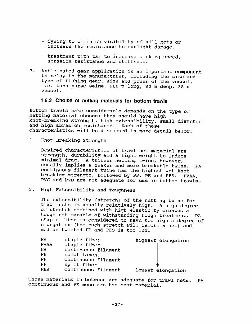
The extensibility stretch! of the netting twine fortrawl nets is usually relatively high. A high degreeof stretch combined with high elasticity creates atough net capable of withstanding rough treatment. PAstaple fiber is considered to have too high a degree ofelongation too much stretch will deform a net! andmedium twisted PP and PES is too low.
highest elongation
lowest elongation
Those materials in between are adequate for trawl nets. PAcontinuous and PE mono are the best material.
-27�
PA
PVAA
PA
PE
PP
PP
PES
staple fiberstaple fibercontinuous filamentmonofilamentcontinuous filamentsplit fibercontinuous filament

3. Abrasion Resistance
Since bottom trawls are subjected to contact withbottom surfaces, and dragged onto rails and ramps, theysuffer the most abrasion damage. PA appears to be the mostabrasion resistant material, although PE mono is excellent.
4. Summary
Compromise usually is the matter at hand when selecting theproper material for a trawl net. PA continuous filaments!and PE monofilaments! are the most common materialsbecause of their technical and economic advantages. PAcontinuous filaments have excellent characteristics: highwet knot breaking strength, high extensibility andelastically, small diameter and high abrasion resistance.Lower price is the main factor in favor of PE foldedmonofilaments. It can be manufactured easily andinexpensively. PE trawls are referred to as being cleanerwith less spiny fish being caught in the meshes because ofthe stiffness of the twine. These also do not catch on
small obstructions on deck, as soft nylon trawls tend todo. PE tends to float, therefore reducing the bottomdamage to parts of the net and permitting reduced flotationof the net.
1.6.4 Choice of netting material for gill nets
A gill net can be defined as a wall of webbing, usuallyassumed to be invisible, which impedes the fish travelpath. Fish become gilled or entangled in the mesh.
Synthetic monofilament! netting is 2-12 times moreeffective at capturing fish than natural fibers cotton orflax or synthetic multifilament! and is widely used.Because of numerous benefits, when affordable, it is thepreferred material for this type of gear. Some of theadvantages of monofilament are:
�! Transparent and invisible in water.
�! Smoother twine surface does allow for less "trashing"of the net.
�! Twine is stiffer so that meshes remain open, it is lesseasily snagged and less surrounding area is affected byentangled fish.
�! Higher elasticity, elongation recovery allows foreasier removal of fish from the net.
-28-

�! Good abrasion resistance
One of the major disadvantages of monofilament is relatedto its nonbiodegradable characteristics. When nets arelost, "ghost nets" are created which will continue fishing
/and destroying the resource. Additionally, because of the/excellent fishing characteristics associated with monofilament, it has become too efficient at capturing fishI and many areas have suffered from rapidly depleted stocks.
Some of the requirements for gill nets appear contradic-tory. Although monofilament is usually clear andinvisible, it is generally too stiff to entangle fish. PAcontinuous filament is the softest of all syntheticmaterials, but due to its bright color, it may be visiblein clear water. Therefore, in order to be effective, thenet must be dyed either green, blue, grey or brown. PAmonofilament is transparent but has a relatively lowbreaking strength with small diameter twine. Twistedmonofilaments combine transparency of monofilaments withthe high strength and softness of a multi-filament.
Most gill nets have bottom and top lines that act as aframe from which the webbing is hung. These lines must bestrong enough to hold up in hauling and setting but mustremain flexible. Synthetic lines are usually adequate forthis purpose.
4.7 References
Commercial fishing vessels and gear, 1957. Bureau ofCommercial Fisheries Circular 48. United StatesDepartment of the Interior. US Government PrintingOffice, Washington, D.C. 61 pps.
FAO catalogue of small-scale fishing gear, 1987. FishingNews Books Ltd, England. 224 pps.
Klust, G. 1982. Netting materials for fishing gear. FAOFishing Manual. Fishing News Books Ltd, England. 169pps-
Klust G. 1983. Fibre ropes for fishing gear. FAO FishingManual. Fishing News Books Ltd, England. 200 pps.
Morton, B.M. 1988. Down East netting: A history and howto of netmaking. Down East Books, Camden, Maine. 143pps.
-29-

Prado, Z. and P.Y. Dremiere. 1988. Fisherman's workbookFAO Fishing Technology Service, Fishery IndustriesDivision. 179 pps.
Tvinevork, An introduction to working with nets. 1987.Fisheries Information Service. Melborne, Florida 70pps ~
Visel, T. and L. Stewart. 1987. A guide to theconstruction of fyke nets. Sea Grant Marine AdvisoryProgram. University of Connecticut. CT-SG-87-08, 16pps ~
Visel, T. and L. Stewart. 1988. A guide to theconstruction of gill nets. Sea Grant Marine AdvisoryProgram. University of Connecticut CT-56-88-04, 26pps ~
von Brandt, A. 1984. Fish catching methods of the world.Fishing News Books Ltd. England, 418 pps.
-30-

CHAPTER 2
BASIC KNOTS USED IN
TWINEWORK K AND KNITTIN NG PROJECTS

Page
2 1 1 Basic Knots................................... 3 3
2.2 Preparation of Toois ............... 35
2.2.1 Sharpening knife ---.----2.2.2 Loading the needle ....
35
35
2.3 Knitting Projects............ ~ t 0 ~ 37
2.4 References ............. ~ ~ ~ ~ ~ 0 ~ ~ ~ ~ ~ ~ ~ ~ ~ ~ ~ ~ 44
2.1.1
2. 1.2
2.1.3
2.1.4
2.3.1
2.3.2
2.3.3
2.3.4
2.3.5
CHAPTER 2
BASIC KNOTS USED IN
TWINEWORK AND KNITTING PROJECTS
Half hitch ..Clove hitch .
Sheet bend or weavers knot ~ .Double sheet bend ..--
Knitting a square piece of webbing .Increasing, widening or creasing -.--Narrowing or bating-- ' ~ 0Reinforcing with a straight selvedgeKnitting a diamond .-
33
33
34
34
37
4041
4242

BASIC KNOTS USED IN
TWINEWORK AND KNITTING PROJECTS
2.1 Basic Knots
The following knots are most commonly used in twinework.Other knots are useful in the fisherman's world and manybooks are available to describe these see Referencesection!.
2.1.1 Half hitch
The half hitch is used to secure twine to a line or rod.The twine is brought around the line and over or under theother part of the line. It is not used alone because itwill easily slide free Figure 2.1!.
Figure 2.1. HBN hitch.
2.1.2 Clove hitch
The clove hitch is a combination of two half hitches. Thisknot is more dependable and is commonly used to secure theinitial loops to begin a knitting project Figure 2.2!.
Figure 2.2. Clove hitch.
� 33�

2.1.3 Sheet bend or weavers knot
The sheet bend is one of the' best joining knots and is thebasis for net making. Care must be taken to seat the knotaround the foundation loop and not let it slip below theloop Figure 2.3!.
Figure 2.3. Sheet bend a! correct b! incorrect.
2.1A Double sheet bend
The double sheet bend is used when initially tying onto orfinishing an area of patching or mending. It is also usedwhen working with slippery twines which do not hold knotswell Figure 2.4!.
Figure 2.4. Double sheet bend.
� 34�

2.2 Preparation of Tools
2.2.1 Sharpening knife
No matter how expensive the knife, it can only be as goodas you make it by sharpening it. Ideally, knives wouldnever rust, break or need to be resharpened. However, saltwater and blood will even corrode stainless steel blades.
Knives can be sharpened on grinding wheels, flat stones,ceramic rods or steels, as well as in the patented "stick-the-blade-in-the slot" devices. Sharpening a knife on awheel or stone is a very involved procedure. It requiresmany hours of practice to develop the right feel.
If the blade is severely damaged, it should be treatedinitially with a coarse wheel and then moved on to finersteel and buffing wheels.
Most commonly used in the field is the sharpening stone.The blade must be held against the sharpening stone at afixed angle. In the proper position, the knife is strokedslowly against the stone in one direction. The angle mustbe changed slightly to hone the cutting edge. When oneside has been completed, turn and do the other side.
Traditionally, sharpening stones have been oiled. The oillubricates the stone and keeps steel dust from clogging thepores. Oil, however, is no longer recommended, because ofthe harm done to the knife by dragging it through oil withsteel grit. Regardless of the lubricant used, the stoneshould be kept clean and can be washed in water or oil.
The best solution to the problem of sharpening your knifeis to keep the blade in good condition in the first place.It should be kept clean and honed frequently, and driedafter use.
2.2.2 Loading the needle
To eliminate any kinks in the twine, before loading theneedle, cut off a long piece of twine from the roll andallow the twists to uncurl.
To wind the needle, follow the steps listed and shown inFigure 2.5.
1. Hold needle with point upwards.2. Pass end of twine around prong and trap under the twine
leading out half hitch!.
-35-

Figure 2.5a. Starting to load the needle.
3. Take twine down and around the heel of the needle andturn the needle 180 over, passing the twine throughthe prong and back down to heel; never turn 360 or itwill cause kinks in the twine Figure 2.5b!.
Figure 2.5b. Continue to load twine.
4. Repeat this procedure, filling needle tightly andturning the needle back and forth until it is loaded.Neither the prong nor the heel should be hidden Figure2.5c! .

Figure 2.5c. The loaded needle should look like this.
If double twine is desired, pull the required length oftwine from the spool, double in middle, make a hook overthe tongue and load normally.
2.3 Knitting Projects
Webbing is constructed by hand by creating meshes inconsecutive rows which increase in depth until the desirednumber of meshes are obtained. The basic knot used is thesheet bend, also referred to as the pickup knot. Thefollowing projects are designed to help the beginner todevelop the skills necessary to accomplish larger projects.
2.3.1 Knitting a square piece of webbing Sx6D!
1. Begin by tying a piece of twine about 46 cm long toform a loop and secure on a hook or nail Figure 2.6!.
Figure 2.6. Form a loop.
-37-

2. Form a series of 8 loops on this loop using the meshgauge and clove hitches Figure 2.7!.
0 NELOO
Figure 2.7. Form series of loops.
3. Turn loop over so that you will be knitting always inthe left to right direction.
4. Using the mesh gauge, you will now create the first rowof webbing using the 8 loops as a base. Remember thegauge only measures the bar length, not the entire meshsize Figure 2.8!.
-38-

Figure 2.8. Creating the first row of meshes.
To form the sheet bend knot, enter the loop from beneathwith the needle, go around the 2 sides and back through theincoming twine Figure 2.9!. Keep the knot in positionwith your fingers.
Figure 2.9. Eniarged view of sheet bend.
Use the heel of the needle to pull the knot tight but besure that the knot does not slip below the loop see Figure2.3!.
-39-

This is the first full mesh. Leave the gauge in positionand repeat the same procedure for the remaining 7 loops.
5. When the last knot is completed, turn the loop over andknit the next row. Continue doing this until 6 rowshave been completed. Cut the loop and pull throughleaving the square piece of webbing open. The finishedproduct should look like Figure 2.10 '
Figure 2.10. A sguare piece of webbing.
2.3.2 increasing, widening or creasing
Increasing, widening or creasing are all terms used todescribe the increasing in the size of the net by addingmore meshes. Where this extra mesh occurs will ultimatelydetermine the final shape of the net. A mesh consistentlyadded on the last of the row will provide a net that slantsat a 45 angle i.e. rectangular tennis net!. It isdesirable to increase in the middle of a row and alternateso that creasings are not adjacent to one other.
To increase, make a mesh with the normal method, then takethe twine and go around the gauge again, but instead oftaking up the next mesh, you should go back through themesh just made. Then continue in the normal manner to thenext mesh Figure 2.11!.
-40-

e LOOKSL! KE
e ToTHt5
edh
Figure 2.11. A creasing.
2.3.3 Narrowing or bating
Narrowing or a ingb t'n means decreasing the size of the net byremoving meshes. Bating should be done evenly, just ascreasing, to avoid distortion of the net.
is done b taking in two meshes instead of one! andBating is one y at the regular sheet bend around both meshes Fi urety j.ng g2. 12! .
Figure 2.12. A bating.
-41-

2.3.4 Reinforcing with a straight selvedge
When knitting a piece of flat webbing, the outer meshes atthe edge hang loose. This is the normal selvedge, but itcan be strengthened by deliberately taking in thedescending strand of the loose mesh with the first knot ineach row. Then proceed to the next mesh in the normalfashion Figure 2.13!.
Figure 2.13. Knitting a selvedge.
Selvedges along the bottom or top of the net may be madesimply by knitting the first and last rows with doubletwine.
2.3.5 Knitting a diamond or a square mesh piece
By knitting a diamond shape and turning it 90, you willcreate a square mesh piece of webbing. The size of thewebbing will depend on the number of rows knitted. Work isstarted at one corner by the formation of one mesh. Thenext row contains two meshes and so on. This is continueduntil the desired length is reached. Meshes are thenreduced one by one by row until one mesh remains. Thiswill form a square piece. If a rectangular net is desired i.e. tennis net! then when the desired depth is achieved,
meshes are reduced at one end and increased on the otherend.
-42-

Start by forming a loop and hook to secure.Form two creasings to increase to 2 meshes in the nextrow.
Form a selvedge and end with a crease.Continue with a selvedge and crease until fourth row.Row five, regular row with no creasing or bating.Last four rows, start with a selvedge and end the rowwith a bating until 1 mesh is left.
1.
2.
3.
4.5.6.
KN I T A 0l A MONO
OP
3 S
6 Crea
7 Selvedge
lO NO Crease or Bate~ 9 Selvedge
l2 Batingl I Selvedg
elvedge
17 END
Figure 2.14. Knitting a diamond.
-43�
To knit the diamond Figure 2.14!:
easing
Creasing
5 Selvedge
~ 8 Creasing

2.4 References
Blanford, P.W. 1973. Netmaking. Brown, Son and Ferguson,Ltd. England. 104 pps.
Dahlem, T. 1978. How to make and mend cast nets. GreatOutdoors Publishing Co. Florida. 72 pps.
Graumont, R. and E. Wentstorm. 1976. Fisherman's knotsand nets. Cornell Maritime Press, Inc. Maryland. 203pps ~
Holdgate, C. 1972. Netmaking. Emerson Books Inc. NewYork. 136 pps.
Lorimer, P.D. 1978. Net mending and patching. PacificSea Grant Advisory Program. Oregon State UniversityExtension Service. USA. 16 pps.
Ludgate, H.T. 1976. Make nets; Here's how. NetcraftCompany, Inc. Ohio. 72 pps.
Morton, B.M. 1988. Down East netting: A history andhow-to of net making. Down East Books, Maine. 143pps-
Winch Q. 1987. Nets and knots. Dryad Press Ltd. London.71 pps ~
-44-

CHApTER 3
BASICC NET DESIGN
GILL NETS

CHAPTER 3
BASIC NET DESIGN: GILL NET
Page
3.1 Basic Net Designs.-... ~ t 0 0 ~ ~ 0 ~ ~ ~ ~ ~ ~ ~ 47
3.2 Types of Gill Nets- 47
3.3 Determination of Mesh Size ...... ~ ~ 0 1 0 ~ ~ ~ ~ ~ ~ 5l
3.4 Hanging Ratio........ 52
3.5 Determination of Net Depth and Length ~ ~ ~ 53
3.6 Determination of Knot Spacing ......-- 55
3.7 Rigging the Gill Net. ~ ~ ~ ~ t ' ~ ~ ~ ~ ~ ~ 57
Positive buoyancy----Negative buoyancy
57
57
3.7.13.7.2
3.8 Net Plan for a Coastal Bottom Set Gill Net ....... 58
3.8.1 Explanation of net plans ....--3.8.2 Construction ~ ~-
59
60
3.9 References 60
3.2.1
3.2.23.2.3
3.2.4
3.2.5
3.2.63.2.7
3.2.8
Anchored nets - ~Coastal nets---Drift nets ~ -....-----.
Drop-line netsEncircling netsFlag netsStaked nets
Trammel nets ....
48
48
48
49
49
50
50
50

BASIC NET DESIGN: GILL NET
3.1 Basic Net Designs
A gill net is simply a wall of webbing of certain mesh sizewhich interrupts the path of fish and captures them by"gilling" or entangling them. By attempting to swimthrough a mesh, the fish will become stuck when thecircumference of its body is too large to pass through themesh. This can occur at the dorsal fin, but most commonlyit will be behind the opercula gill cover! and the gills Figure 3.1!. Other larger or smaller fish may becomeentangled with spines, fins or other body parts.Entangling nets or trammel nets! are designed speciallyfor entangling fish.
Figure 3.1. The typical manner in which a fish is" gilled".
Gill nets are maintained vertically in the water by floatson the upper line and by weights in the ground-line.Floats and leads should be evenly distributed. The numberand type of floats and leads will vary according to fishingmethod and design.
3.2 Types of Gill Nets
Gill nets are usually set across the direction of themigrating fish. They can be placed in many different ways:there are bottom nets set on or near the bottom to catchdemersal fish; there are anchored or free drifting nets;there are encircling and dragged gill nets.
-47�

3.2.1 Anchored nets
By using anchors, these nets are usually set across tide inlaces where they might be subject to heavy tides,p ac
currents, and fouling. Anchored gill nets may be use d tofish the surface, bottom, or midwater by adjusting thelength of the bridles, by the use of float or drop lines,and by adjusting the length of the anchor line Figure3.2!.
Figure 3.2. Anchored bottom gill net.
3.2.2 Coastal nets
Using a heavy lead line and float line will allow a gillnet to be used in heavy currents and tides; this rigging isgenerally known as a coastal net. Extra floats and leadsmay be employed.
3.2.3 Drift nets
Drift gill nets, most often used in currents and tides,are allowed to drift freely and are not fixed or set.Usually, one end of the gill net can be secured to thefishing vessel, with the net allowed to drift past aselected area of good fishing ground. Depending on theabundance of sharks or non-target species in the area,fishing time can be determined to prevent fouling Figure3.3!.
-48�

Figure 3.3. Drift net.
3.2.4 Drop line nets
A drop line net is an adjustable gill net, using drop linesto hold it below the surface. Drop lines are attached tothe floatline, and prevent surface fouling from jellyfish,seaweed and other floating debris. The leadline is keptoff the bottom, thus avoiding bottom fish and crabs thatmight otherwise become entangled in it Figure 3.4!.
Figure 3.4. Dropline net.
3.2.5 Encircling or run around gill nets
This gill net is often set to circle a certain location orschool of fish. Fish are then frightened into the net.Encircling gill nets are often hung full with extra webbingand can be operated by one or two boats Figure 3.5!.

Figure 3.5. Encircling net.
3.2.6 Flag nets
Flag nets are constructed of limp, soft multifilamentwebbing, and use no weighted bottom line leadline!. Theyare designed for use in ponds and lakes where there islittle or no current.
3.2.7 Staked nets
A staked net is a gill net set out along a series of stakesor poles driven into the bottom. The stakes provide asturdy foundation for setting gill nets in strong currents,and keep the net set properly.
3.2.8 Trammel nets
Trammel nets consist of an inside wall of loose small meshwebbing and two outside walls of large webbing. All threewalls are hung to the same float and lead line. The net'sdepth is determined by that of the outside walls. Theinside net has a greater depth and hangs loosely betweenthe outer panels of webbing. Fish are usually captured byentanglement. As the fish passes through the larger outermesh, it hits the small mesh netting and carries it throughone of the openings of the outer large-mesh webbing. Apocket of small mesh webbing is formed, trapping the fish.Most trammel nets are hung with a 0.5 hanging ratio. Thehanging of trammel nets varies by area and type of fish Figure 3.6!.
-50�

Figure 3.6. Trammel net.
Once a suitable type of net has been selected, it isnecessary to determine its optimum size, mesh size, twinethickness, hanging ratios, color, sizes of lines, warps,rigging and anchors. Local regulations and licensingrestrictions must be considered.
3.3 Determination of Mesh Size
The size of target fish directly determines the mesh sizeused in a gill net. This must be carefully examined sinceif the mesh is too big, the fish will pass through thewebbing; if too small, the fish will not gill.
Two approaches to determining the correct mesh size aresuggested below:
1. Tie a piece of twine immediately behind the gill plateson a fish of the size you desire. Slip off twine loopand measure it.
2. A mathematical approach to estimating the mesh openingin terms of the maximum girth or circumference of thefish G.
Mo=K.G
where
K is between 0.4 for long narrow bodied fish and 0.44 fordeep short-bodied fish.
-51-

G = maximum circumference of fish.
Mo = mesh size.
For example; a herring of 10.2 cm circumference, would needa mesh size of 4.08 cm.
Mo = 0.4 x 10.2 cm = 4.08 cm
3.4 Hanging Ratio
The hanging ratio is expressed as either a fraction ordecimal and it refers to the ratio between the stretchedrope length to stretched webbing length.
Example: 10 cm webbing to 5 cm of rope is equal to:
Hanging Ratio = 5 cm/10 cm = 1/2 = 0.5
For example, 120 m of stretched webbing hung to a line witha 0.5 hanging ratio yields a 60 m long net.
Hanging ratio determines howcopen" or uclosed'i eachindividual mesh is.
8.25 t-m8.25 cm
Hanging ratio = 0.5 Hanging ratio = 0.25
Figure 3.7. Examples of hanging ratios.
-52�
The hanging ratio refers to how the webbing is hung to theleadline or floatline. It compares the length of stretchedwebbing hung to the length of leadline or floatline anddescribes how slackly or tightly the webbing is hung to anyrigid or flexible frame. Although other terminologiesdescribe this relationship, the one most commonly used isthe hanging ratio.

Drift gill nets are usually hung by a ratio of 0.5 to 0.7.Values as low as 0.3 are sometimes used to increaseentangling in bottom set nets, although 0.5 is the usualvalue.
3.5 Determination of Net Depth and Length
The depth of a gill net is a function of the hanging ratioand the hanging coefficients. Hanging coefficients are thevalues used to calculate the width or depth of a given meshsize hung at various ratios.
The A hanging coefficient is equal to the hanging ratio.The B coefficient is calculated geometrically by theformula:
B = 1-A2
To calculate the opening or width of a mesh, multiply the Acoefficient by the mesh size.
A
width = 0.5 x 10.0 cm = 5.0 cm so 5.0 cm
B will equal 0.87
To calculate the height of a mesh, multiply the Bcoefficient by the mesh size.
length = 0.87 x 10.2 = 8.7 cm so = 8.7 cm
Table 3.l. Hanging Terminology for Nylon Nets
Han in Ratio Han in Coefficient
~Primmr
-53�
1
0.8
0.66
0.6
0.58
Q0.50.45
0.4
0
1
0.8
0.66
0.6
0.58
0.5
0.45
0.4
0
0
0.8
0.75
0.8
0.82
p
0.89
0.92
1.0

HANGING COEPPICIENTS A, B!
To calculate the opening ofwidth of a mesh, multiply the Acoefficient by the mesh size.To calculate the closure orheight of a mesh, multiply theB coefficient by the mesh size.
Figure 3.8. Hanging coefficients.
When the width and length of each mesh is known, it ispossible to calculate the number of meshes needed to attainthe depth and length desired.
Example: To obtain a gill net of 3.3 m in depth, how manymeshes deep should the panel be?
Hanging ratio = 0.5Secondary hanging coefficient = 0.87Mesh size = 10.0 cm stretchDepth of gill netting = ?Desired depth = 3.3 m
Depth in meshes! = Desired de th in cmB coefficient X Mesh Size
Depth in meshes! = 330 cm = 33IY = 38 meshes.87 x 10.0 cm 8.7
Depth of gill netting desired for this depth equals 38meshes.
-54-

The desired length of the net is determined by the abilityof the crew and boat to handle it efficiently on board.Usual net length is between 15 and 200 m depending onfishing conditions and handling facilities. Many timesgill nets are not used as single nets; but can be linkedtogether. These can be set up as straight-walls,bow-shaped or other patterns.
3.6 Determination of Knot Spacing
Once the hanging ratio and desired length have beendetermined, the amount of hanging line and webbing can becalculated and the hanging can begin. Distance betweenknots tie length! per phase length can be calculated. Thenumber of meshes per tie is based on the experience of thefishermen. Three meshes per tie is ideal, but requiresmany more knots than 10 meshes per tie. After specifyingthe number of meshes per tie, the tie length TL! iscalculated as follows:
TL = � meshes per tie! x stretch mesh length! x hanging ratio!
Example:
For a gill net with a 10.0 cm mesh and a hanging ratioof 0.5 and a specified number of meshes per tie of 3:
TL = �! x �0.0! x �.5! = 15.0 cm
So 30.0 cm of stretched webbing � meshes! will be hung in15.0 cm or three 10.0 cm meshes are hung in each 15.0 cmphase Figure 3.9!.
15.0 cm
Figure 3.9. Determination of knot spacing.
Once the size and type of net is determined it is best tocalculate the exact quantity of materials to purchase. Youmust know the following:
-55-

1. Mesh size desired2. Length & depth3. Hanging ratio4. Twine type and diameter5. Rigging considerations
You have decided that the desired gill net is 90.0 m long,2.0 m deep, with a hanging ratio of 0.5. The twine typewill be a multifilament nylon 4 139 total Tex, and 8.25 cmmesh size. The webbing is available at depths of 30meshes. There are 85 meters of webbing per Kg.
The following questions must be answered:
1. How many kilograms of webbing are needed?2. Are 30 meshes deep sufficient for the net?3. What is the tie length between knots to hang the
webbing, based on a specified number of meshes pertie?
SOLUTIONS
1. To determine the weight of the webbing required toconstruct this net, first calculate the g ofstretched meters of webbing needed to build thenet.
1
Hanging ratio x length = Length of stretched webbing
x 90.0 m = 180.0 m of webbing1
Since there are 85 m/Kg of this material, you mustdetermine how much 180.0 m of gill netting weighs.
180.0 2 1 2 5 K Since the marine suppliers85 ' g request that you round up to
the nearest 0.5 Kg!
2. The depth of the net is a function of the Bcoefficient �.87! and the mesh length 8.25 cm!.Each mesh has a depth of 0.87 x 8.25 cm = 7.18 cm.30 meshes vill have a depth of 30 x 7.18 cm = 215.4cm or 2.15 m.
3. To calculate the tie length based on 3 meshes pertie, 8.25 cm mesh size, and 0.5 primary hangingratio:
-56�

� meshes/tie! 8.25 cm! �.5! = 12.4 cm
3.7 Rigging the Gill Net
The most frustrating task of rigging a gill net is theplacement and calculation of the floats and leads. Thisis easier than it appears to be and prevents theembarrassment of having your bottom gill net float whenyou don't expect it to.
First, all positive buoyancies must be determined. Thisincludes the webbing, lines and floats. We' ve determinedthat we will construct a 106 m long bottom gill net with0.79 cm polypropylene lines and floats of 100 gram liftspaced 88.9 cm apart. The net will have 200 leads eachweighing 50 grams. Will the net sink?
3.7.1 Positive buoyancy
212 m of PP line float and lead lines! have a positivebuoyancy of 154 grams/30 m therefore, 7 x 154 = 1078 g or1.08 Kg buoyancy.
Each float has a buoyancy of 100 grams, and there arefloats placed every 89 cm in a line of 106 m, therefore120 floats are placed on the float line producing abuoyancy of 12,000 grams or 12 Kg.
Total buoyancy = 1.08 + 12.00 = 13.08 Kg
3.7.2 Negative buoyancy
200 leads x 50 grams = 10,000 grams or 10 Kg
There is not enough weight to set the gill net on thebottom, so it is necessary to increase the number ofleads. 300 leads x 50 grams = 15,000 grams or 15 Kg wouldbe sufficient for still water. However, environmentalconditions such as swift currents, will require additionalfloats and weights to maintain the gill net in a verticalposition Figure 3.10!. Trial and error will usuallyresult in the proper relationship in these situations,although Fridman �986! offers a mathematical solution tothis dilemma.

Figure 3.10. Configuration of a gill net in a current.
3.8 Net Plan for a Coastal Bottom Set Gill Net
The following net plan is for a coastal gill net, with abottom set. It is a simple design and can be modified tomeet the criteria for the size and species desired Figure3.11 A and 8!.
30 PP$ 'i,5 mm3.05
PP j! 1.5
25 30 PP f! 1.5 mmG1LL NET PLAN
Figure 3.11. Gill net plan: View A.
-58-

B.
2 5 PL 119 g f /1. 2 I E =0,5
E =0.87
120 Pb 56 gf/0.25m E =0.5
RIGG I NG PLAN
Figure 3.it. Gili net rigging plan: View B.
3.8.1 Explanation Of net plans
pp
PApolypropylenepolyamide nylon!plasticlead
diametergrams associated with either lifting or sinkingforce
A or B hanging coefficient
PL
Pb
gf
The length of the float line and lead line will be 30meters of polypropylene rope of 1.5 mm. The up and downline will be approximately 3.05 meters.
The second net plan explains the hanging and rigging ofthe net. The hanging coefficient along the float-linesand lead lines is 0.5; while the B coefficient along the
-59�
The first net plan, A!, provides a view of the netindicating the number of meshes in width and depth, thesize of the meshes and construction materials. The netwill be 429 meshes in length, and 25 meshes in depth. Thewebbing will be constructed of polyamide monofilament witha diameter of 0.5 mm. The mesh size is 140 mm stretchedmesh length.

up and down line is 0.87. There are 25 plastic floats of119 gf each placed every 1.2 meters. There are 120 leadsof 56 gf each placed every 0.25 m.
3.8.2 Construction
1. Choose 4, size of floats and leads, material ofconstruction, mesh size, length and depth. Nake anyadaptations to net plan.
The following instructions pertain to the net planprovided:
2. Take 1 rope 10 meters long and mark off every 140 mm.Hang taut between 2 solid posts.
3. On the same posts, extend the head rope and foot ropealongside the marked rope. Make marks on these toline up together.
4. Begin seizing webbing to float line starting with afloat. Seize 2 meshes to a phase length, using aclove hitch. Place floats every 6 ties. If twopersons are working, hang the float line and the footrope at the same time. If only a one personoperation, hang 10 meters of the float line first,then the foot rope. Continue the 10 m length, thenretie the next 10 m, mark spacing lengths and continueseizing webbing until the 30 m are completed.
3.9. References
Atlantic and Gulf Fishing Supply Corp. Commercial fishingsport fishing and the marine supplies, equipment catalog.
Fridman, A.LE 1986. Calculations for fishing gear designs.Food and Agriculture Organization of the United Nations.Fishing News Books Ltd. Surrey, England 241 pps.
Visel, T and L. Stewart 1988. A guide to the constructionof gill nets, University of Connecticut Sea Grant MarineAdvisory Program. CT-SG-88-04.
von Brandt, A. 1984 Fish catching methods of the world.Fishing News Books Ltd. Surrey, England. 417 pps.

CHApypR ~
BAS~gIC we> z~.,
RA.~ ~ETS

Page
4.1 Introduction to Trawl Net Designs -.... ~ ~ ~ ~ 64
4.2 The Basic Yankee Trawl Net 65
4.3 The Tapering of Webbing- ~ ~ ~ ~ ~ ~ 69
69
71
74
77
774.3.5
4.4 Development of a Cutting Plan ................. 80
4.4. 1
~ ~ ~ ~ ~ 80
864.4.2
4.5 Reinforcing Net Sections.... ~ ' ~ ~ ~ ~ ~ ~ 90
904.5. 14.5.2
92924.5.3
4.6 Assembly of the Net- 98
98
~ 0 ~ ~ ~ ~ ~ 101
4.6. 1
4. 6.2
4.6.3
105
4.7 Hanging the Net to the Mouth Frame................. 106
4.3.1
4.3.2
4.3.34.3.4
4.7. 14.7.24.7.3
4.7.4
CHAPTER 4
BASIC NET DESIGN: TRAWL NETS
Introduction-
Determining the cut-Calculating the taper ~ ~ ~ ~ ~ ~ ~ 0 ~ ~
Summary of cutting and tapering formulasfor body tapers of trawl net sections---Cutting tapers in webbing--- ' ~
Minimum panel size required for a singleor pair of net sections ~-------The cutting plan ....
Introduction ~ ~ ~ 0
Reinforcing the belly and square netsections ~ ~ ~ ~ . o ~ ~ -i-- ~ ~ ~ e ~ ~ ~ ~ ~ ~ ~ ~
Reinforcement of wing net sections ~
The upper panel .....The lower panel ..... ~ ~ ~ ~
Lacing the upper and lower panelstogether ~ ~ ~- ~ ~
Hanging ratioThe mouth frame dimensions
Headrope and hanging line constructionHanging the webbing to the mouth frame
106
106
108109

Page
4.8 Rigging the Traw} Net. 112
4.9 References 121
4.8.1
4.8.2
4.8.3
4.8.4
4.8.5
The sweepF 1 oats ~ ~ ~ r ~ ~ ~ ~ ~ ~ ~
Extension pieces.........The cod-end ~ - ..
Working and strengthening ropes ............
112
115
115
117
118

BASIC NET DESIGN: TRAWL NETS
4.1 Introduction to Trawl Net Designs
The bottom trawl net is a funnel � shaped net that is draggedacross the bottom of the sea and is designed to capture thefish in the near-bottom water. The mouth of the net isopened either by a set of otter doors in single boat ottertrawling, or by the spread of the warps from two boats inpair trawling. This chapter deals with the constructionand rigging of the bottom trawl net.
Except for the simplest nets, such as gill nets, most netsare made from a number of panels of webbing of the same ora different mesh size. These panels are cut out of a sheetof webbing to the correct sizes and shapes, and are thenjoined together to give the required shape. Of all thenets used for fishing, the bottom trawl net is probably themost complicated, in that it involves the use of a numberof panels of webbing which are cut and joined in variousways.
There are many different designs of bottom trawl nets usedin the modern ground fisheries. These include flat nets,high rise nets, balloon trawl nets, four panel box trawlnets, and others. Once the procedures for making the mostbasic trawl net are understood, it should be possible forthe twineperson to make any net, providing that theappropriate net plan is available.
When learning to construct a trawl net, it is morepractical to first work with a model. A model is a scaled-down version of a full-scale net. The model described inthis chapter is for learning purposes only; it is not aproperly scaled engineering model used to determine netperformance.
The net designs used to illustrate the construction of abottom trawl net in this chapter are a full-scale, modified3/4 Yankee trawl net and a model Yankee trawl net. TheYankee trawl net is a basic flat net design used in the NewEngland ground fisheries. The full-scale net is sometimesreferred to as the 11.9 by 16.4 �9 x 54! net, however, themodified version described in this chapter is a 11.2 by16.7 �7 by 55! net. These numbers refer to the length inmeters of the headrope and sweep, respectively.
By scaling a net design up or down, changing the netsection sizes and the headrope and sweep dimensions, netscan be built to suit the size and power of individual
-64-

vessels e.g., Yankee 35: 15.2 by 21.3 �2 x 72!; Yankee 3618.3 by 24.4 �0 x 80!; Yankee 41: 24.4 x 30.5 80 x 100!!.The net itself is made up of a number of sections of shapedwebbing. When all these sections have been joinedtogether, the net is attached to the mouth frame. Theframe around the mouth of the net consists of threedifferent parts: the headrope, the hanging line, and theup and down line. Once the net has been hung to the mouthframe, the appropriate cod-end, working lines, sweep orfootrope, rigging and otter boards for the particularapplication are arranged.
4.2 The Basic Yankee Trawl Net
The net is constructed of a number of sections of shapedwebbing, as shown in Figure 4.1. As the headrope is 5.4 mshorter than the sweep, the top of the net overhangs thebottom of the net. This overhang is important inpreventing upward escape of fish. The section of twineforming the overhang is termed the square.
ND
DOOR
Figure 4.1. Basic trawl design.
The upper and lower panels of the net are built separatelyand then joined to make the complete net. The arrangement ofthe upper and lower panels is shown in Figure 4.2, which isthe net plan for the full-scale 3/4 Yankee trawl net andFigure 4.3, which is the net plan for the model Yankee trawlnet.
-65-

Figure 4.2. 3/4 Yankee trawl net.
-66-

Figure 4.3. Model Yankee trawl net.

The upper panel of the net is made up of sections thatinclude one square, one belly, and two top wings. Thelower panel of the net is made up of sections that includeone belly identical to the top belly! and two bottomwings. Note that, due to the square being inserted toprovide overhang, the bottom wings are longer than the topwings by the depth of the square.
The various sections may be made in several ways:
1.! The twine may be knitted to the required shape andsize. This is a slow and monotonous task and veryrarely is undertaken today.
2.! The sections may be purchased already cut to size.Host fishing supply houses keep a stock of thevarious sections for standard nets.
3.! The sections may be cut out from standard sheets ofwebbing.
The construction of a bottom trawl net from a net plan and asingle sheet of webbing is described in this chapter, andincludes the following operations:
1.! Determine the taper for each section of net.
2.! Calculate the minimum size of a panel of webbingrequired to cut individual sections or pairs ofsections.
3.! Develop a cutting plan for all the net sections froma panel of webbing of standard depth.
4.! Cut the net sections.
5.! Reinforce the sections with heavier or double twineas required.
6.! Assemble the upper and lower panels of the net bysewing sections together.
7.! Lace the upper and lower panels, forming a goreseam and a complete net.
8.! Construct the mouth frame: headrope, hanging line,and up and down line.
9.! Hang the assembled net to mouth frame.
-68-

10.! Complete the rigging of the net, sew on thecod-end, knit on gussets, attach the sweep, etc.
Each of these topics are presented in the remainingsections of this chapter, with specific examples applied tothe 3/4 Yankee trawl net, and the model Yankee trawl net.
4.3 The Tapering of Webbing
4.3.1 Introduction
Tapering is the art of shaping or cutting a section ofwebbing to specific dimensions. The twineperson usuallystarts with a panel of webbing cut along meshes pickups!and siders points!. This is referred to as a square panelof webbing, although it may not actually be square Figure4.4!. The webbing is oriented along the "run of thetwine", or the direction that, when the webbing isstretched or pulled in, the knots tighten. "Cross-twine"is the direction at a right angle to the "run of thetwine", where the knots loosen when stretched.
Mesh size for a panel of webbing is measured in two ways.The manufacturer of webbing refers to the mesh size as thedistance between knots center to center! when the webbingis stretched along the "run of the twine." Some fisheriesregulatory agencies refer to the mesh size as the actualopening in the mesh. The mesh size can be expressed ininches, centimeters or millimeters. Twine size is usuallyexpressed in terms of diameter in millimeters in theAmerican thread count system.
Tapers are cut into webbing, leaving points, bars, andmeshes Figure 4.5!. Tapers are divided into three types.The jib taper is cut leaving meshes and bars. The bodytaper is cut leaving points and bars. The all bars taper actually one point and then all bars! separates the bodytapers from the jib tapers.
If the webbing is hung such that the individual meshes aresquare in shape, the jib taper is between the all meshes orpickups taper and the all bars taper, and may be thought ofas a taper between 45 and 90 degrees. The body taper isbetween the all points or siders taper and the all barstaper, and may be thought of as a taper between 0 and 45degrees Figure 4.6!. The tapers that are cut in mosttrawl net sections are body tapers. Jib tapers aretypically used in reinforcing wedges or gussets that areknit into the quarters of the trawl net.
-69-

I 2 5 4 5 6 7 8 9 IO Ii l2 l3
12
I2 I/2'i w I Ae
Figure 4.4. A square section of webbing, 13 meshes wide by 121/2 meshes deep.
BAR POI NT
BAR
Figure 4.5. Meshes, points and bars.
-70-

LENGTHALL MESHES or PIC KUPS
0 ON
R'E MESHES
Figure 4.6. Angles resulting from cutting tapers.
4.3.2 Determining the cut
The cut is the number of meshes lost in making a taper in apanel of webbing of specified depth. To determine the cut ofa section of webbing that is symmetric, and thus will haveidentical tapers at each end, the following formula is used.
WE � NE
where:
This formula is useful in calculating the cut of a belly orsquare section taper because they are symmetric sections Figure 4.7! .
-71-
M ILICIV!
OErII-
O0
C = cut of belly or square section in meshesWE = number of meshes in the wide end of
the section
NE = number of meshes in the narrow end ofthe section

Wide End
Narrow EndCut Cut
For the 3/4 Yankee trawl net example:
1.! The belly section of the net is 100 meshes at thewide end, 40 meshes at the narrow end, and 80 meshesdeep �00 x 40 x 80 D!.
WE � NE 100 � 40
30
30 meshes
2.! The square of the net is 130 meshes at the wide end,100 meshes at the narrow end, and 20 meshes deep �30x 100 x 20 D! .
WE � NE 130 � 100 30
15
C = 15 meshes
The wings of a bottom trawl net are not symmetric. Theinside edge of the section is cut with a straight barstaper. The outside edge of the section is cut with a bodytaper Figure 4.8!. T'o determine the cut of that outsidetaper, the following formula is used:
-72�
Figure 4.7. Symmetric section belly or square!.
RUN
of the
TW INE

where:
WE = number of meshes in the wide end of the wing
NE = number of meshes in the narrow end of thewing
number of meshes in the depth of thewing
D
Cut
Figure 4.8. Asymmetric section wing!.
Note: if the cut is negative, use the absolute value ofthe cut, that is, ignore the negative sign.
1.! The upper wing of the net is 40 meshes at the wideend, 9 meshes at the narrow end, and 30 meshes deep�0 x 9 x 30 D! .
-73-
NE + D � 1 � WE
cut of wing in meshes
For the 3/4 Yankee trawl net example:
RUN
of the
TWINE

C = NE + D � 1 � WE = 9 + 30 � 1 � 40 = -2
C = /-2/ = 2 meshes
2.! The lower wing of the net is 30 meshes at the wideend, 21 meshes at the narrow end, and 50 meshesdeep �0 x 21 x 50 D!.
C = NE + D � 1 � WE = 21 + 50 � 1 � 30 = 40
C = 40 meshes
For the model Yankee trawl net example, the application ofthe cut formulas results in the following:
1.! Belly section �4 x 10 x 21 deep!C = 7 meshes
2.! Square section {31 x 25 x 5 deep!C = 3 meshes
3.! Upper wing section {10 x 3 x 8 deep!C = 0 meshes
4.! Lower wing section � x 5 x 13 1/2 deep!C = 10 1/2 meshes
4.3.3 Calculating the taper
2 x CUT
DEPTH � CUT
BARSBODY TAPER
POINTS
The body taper is expressed as a fraction in bars andpoints. When cutting the body taper, the twinepersonalways begins at the wide end with the points. The taperfraction is always reduced to the simplest form, thensubdivided into a sequence of bars to a single point orpoints to a single bar.
If the taper formula results in a whole number �B/1P,2B/1P or 1B/1P! then, the taper sequence is simply repeatedas it is cut into the webbing, and is sometimes referred toas a straight taper.
-74�
Having determined the cut or the number of meshes lost inmaking a taper in a panel of webbing of given depth, the
;,taper sequence is calculated. The body taper formula isused when the cut is less than the depth, as is usually thecase for trawl net wings, belly and square sections.

If the taper formula results in a fraction that reduces toa mixed number �B/4P = 1 3/4!, then a taper consisting ofan alternating sequence of bars to a single point is cutinto the webbing, and is referred to as a mixed taper. Inthis case, to cut the smoothest or most uniform taperpossible, the fraction is divided into a mixed sequence oftapers that, when taken together, result in the originalfraction. This mixed taper sequence is determined from themixed number. The denominator of the fraction indicates
the number of tapers in the mixed sequence of 1 point each.The whole number indicates the base number of bars in eachof the tapers. The numerator of the fraction indicates thenumber of tapers with bar cuts, 1 unit greater than thebase. If the fraction is greater than one-half, the mixedtaper sequence begins with the larger bar cuts; if thefraction is less than half, the mixed taper sequence beginswith the smaller number bar cuts. Considering the previousexample, the body taper formula results in 7B/4P; the mixednumber is 1 3/4; the mixed taper sequence will be 4 tapersof 1 point each, the base number of bars to be cut in eachtaper is 1, however, 3 of the tapers will be 1 more than 1bar, or 2 bars. Because 3/4 is greater than 1/2, the mixedsequence will begin with the larger bar cuts, or 2 bars.The resulting mixed taper sequence is 2B/1P, 2B/1P, 2B/1P,1B/1P, or 3�B/1P! and 1�B/1P!.
If the body taper formula results in a fraction less thanone, 1B/2P or 4B/7P, the result is referred to as a reversetaper because the number of bars in the taper is less thanthe number of points. The reverse body taper can berepeated or mixed. The reverse taper �B/6P! is repeatedas it is cut into the webbing. The reverse mixed taper�B/7P! is subdivided into a reverse mixed taper sequenceas done previously for the mixed taper sequence, however,in this case the result is the reciprocal 3 �B/2P! and 1�B/1P! .
For the 3/4 Yankee trawl net example,
1.! In the belly of the net, the cut is 30 meshes andthe depth is 80 meshes. Therefore, the taper is:
2 x 30 6B2 x C
D � C 80 � 30 5p
-75-

This is a mixed taper, and the mixednumber is 1 1/5. The resulting mixedtaper sequence is 4 �B/1P! and 1 {2B/1P!.
2.! In the square of the net, the cut is 15 meshes andthe depth is 20 meshes. Therefore, the taper is:
2 x C 2 x15 30 6B
20 � 15D � C 1P
This is a straight taper.
3.! For the upper wing of the net, the cut is 2 meshesand the depth is 30 meshes. Therefore, the taperj s.
2 x C 2 x 2 4 1B
D � C 30 � 2 28 7P
This is a reverse taper.
js
2 x C 2 x 40 80 8B
D � C 50 � 40 10 1P
This is a straight taper.
For the model Yankee trawl net, the application of thetaper formula results in the following:
1.! Belly, �4 x 10 x 21 deep!,where C = 7 meshes, the taper = 1B/1P.
2.! Square, {31 x 25 x 5 deep!,where C = 3 meshes, the taper = 3B/1P.
3.! Upper wing, �0 x 3 x 8 deep!,where C = 0, the taper is all points.
4.! Lower wing, � x 5 x 13 1/2 deep!,where C = 10 1/2, the taper is 7B/1P.
-76-
4.! For the lower wing of the net, the cut is 40 meshesand the depth is 50 meshes. Therefore, the taper

4.3.4 Summary of cutting and tapering formulas for body tapersof trawl net sections
Symmetric Section CUT Belly and Square! = WE � NE! /2Asymmetric Section CUT Wing! = NE + D � 1 � WETAPER Body! = � x C! / D � C! .
Note: These formulas can be algebraically rearranged forspecial purposes. For example:
WE Belly of Square! = NE + 2 T x D! / � + T!
WE Wing! = NE + D � 1! � T x D! / � + T!
NE Belly or Square! = WE � 2 T x D! / � + T!
NE Wing! = WE+ 1 � D! + TxD! / �+ T!
4.3.5 Cutting tapers in webbing
The cutting of tapers into webbing is straightforward if afew simple rules are followed:
1.! Always begin to cut the taper at the WE of thesection of webbing.
2.! Always begin the taper sequence with the point orpoints.
3.! When cutting tapers in wing sections, if the NE + Di~s rea ez � than-the-WE,. the cutting of the taperbegins at the NE in place of the WE. That is tosay, the WE becomes the NE for tapering purposes.Conversely, if the ~NE is equal to or less thanthe WE, then the taper is cut from the WE as usual.
For illustration purposes, the tapering of individualsections of a model Yankee trawl net is presented.
1.! The belly sections of the model net are 24 x 10 x21 deep and the taper is 18/1P. The tapers are cutas shown in Figure 4.9. First, a square section ofwebbing, 24 meshes wide by 21 meshes deep, isidentified in the larger panel of webbing. Thenone corner of the wide end is located and the tapersequence is cut, beginning with the point or
-77�

points, then the bar or bars. The taper sequenceis repeated if necessary for the required depth ofthe section. Then, the opposite corner of the wideend is located by counting over the number ofmeshes in the wide end from the first corner mesh.The second taper is cut. If the tapers werecalculated and cut correctly, the number of meshesin the narrow end of the resulting section ofwebbing should be the number specified in the netplan for that section.
Figure 4.9. Model Yankee trawl net belly section.
2.! The square section of the model net is 31 x 25 x 5deep and the taper sequence is 3B/1P. The cuttingof the tapers is shown in Figure 4.10, and theprocedure is similar to that described for thebelly section.
-78-

Figure 4.10. Model Yankee trawl net square section.
St. bars St. bars Taper.'AllDeep Deep p Points
lOlo
Figure 4.1t. Model Yankee trawl net upper wing sections.
3.! The upper wing sections of the model net are 10 x 3x 8 deep and the taper is all points. As notedpreviously, the cutting of wings requires specialconsideration. In this case, NE + D is greaterthan the WE; therefore, the tapering begins at theNE. The inside edge of the wing is tapered with astraight bar cut after the first point for the 8mesh depth of the wing. The outside taper is cutfrom the NE starting with a point Figure 4.11!.

4.! The lower wing sections of the model net are 7 x 5x 13 1/2 deep, and the taper is 7B/1P. In thiscase, the NE + D is greater than NE, therefore, thetaper begins at the NE. The inside edge of thewing is again tapered with a straight bars cutafter the first point for the 13 1/2 mesh depth ofthe wing. The outside taper is cut from the NEstarting with a point, Figure 4.12.
,152Deep
I5�. 2-
DeepToper,'
1P/7E1
Figure 4.12. Model Yankee trawl net - lower wing sections.
4.4 Development of a Cutting Plan
4.4.1 The minimum panel size required for a single or pairof net sections
The formulas for determining the minimum dimensions for apanel of webbing are based on the following:
-80-
Having inspected the trawl net plan, and calculated the cutand taper for each section of the net, the twineperson mustnext determine the amount of webbing required for eachsection of the net, and then assemble these panels into acutting plan, The objective is simply to determine howmuch webbing is required to construct the bottom trawl netwith a minimum of waste.

1.! When joining two panels of webbing together bysidering, a half mesh is gained or added to the sumof the widths of the individual panels.
2.! When cutting tapers into a panel of webbing, a fullmesh is lost from the panel, and from the sum ofthe two resulting sections.
WE NEMINIMUM PANEL WIDTH = � � � � + ---- + 1/2 mesh
Single Section! 2 2
WE = the number of meshes in the wide end ofthe section
Where:
NE = the number of meshes in the narrow endof the section.
The depth of the panel of webbing is the same as the depthof the net section.
For example, the construction of a 3/4 Yankee trawl netrequires a single square section. This section is 130 x100 x 20 deep.
NEWE
MINIMUM PANEL WIDTH
2+ 1/2 mesh
130 100
+ 1/2
65 + 50 + 1/2
Width = 115 1/2 meshes
The resulting minimum panel size is 115 1/2 x 20 deep.
The cutting and assembly of a single section from theminimum size panel is illustrated for the square section ofthe model Yankee trawl net. The dimensions of this sectionare 31 x 25 x 5 deep. The minimum panel width required is:
-81-
A single symmetric section of a trawl net can be cut from asquare panel of webbing with no waste and little additionaleffort. The minimum dimensions of a square panel ofwebbing required for this single net section is determinedusing the following formula:

WE NE
+ + 1/2 mesh2 2
MINIMUM WIDTH
31 25
+ 1/2
15 1/2 + 12 1/2 + 1/2
28 1/2 meshes
The minimum panel size is 28 1/2 x 5 deep.
The procedure for cutting and assembling this panel into asingle section is as follows Figure 4.13!:
1.! Count in from a whole mesh corner along the meshes orpickups about one half the number of meshes in theWE. This marks the wide end corner mesh.
1
2.! Cut the specified taper sequence into the webbing.
3.! Rotate one of the resulting sections, and sider toremaining section. Start on the three-legger, form ahalf mesh, sider to the bottom of the section, formthe last half mesh, and finish the three-legger.
Note that when cutting two tapers simultaneously with oneactual cut, one of the tapers will be out of sequence by asingle bar or point, depending on the taper sequence.
MINIMUM PANEL WIDTH = WE + NE + 1 1/2 meshes Pair of Sections!
Where: WE = the number of meshes in the wide end of thesection
NE = the number of meshes in the narrow end ofthe section
-82�
A pair of symmetric or asymmetric sections for a trawl netcan be cut from a square of webbing with no waste using thefollowing formula for the minimum width of the panel.

Figure 4.13. Cutting and assembly of the square section for the model Yankee trawl net.
The depth of the panel of webbing is the same as the depthof the section.
For example, the construction of a 3/4 Yankee trawl netrequires a pair of belly sections. An individual section
-83�

is 100 x 40 x 80 deep. The minimum panel width for a pairof belly sections is:
MINIMUM PANEL WIDTH = 100 + 40 + 1 1/2141 1/2 meshes
The resulting minimum panel dimensions are 141 1/2 x 80deep.
A pair of upper wing sections for the 3/4 Yankee trawl netrequires a panel of webbing 50 1/2 x 30 meshes deep. Apair of lower wing sections for the 3/4 Yankee trawl netrequires a panel of webbing 52 1/2 x 50 meshes deep. Thecutting and assembling of a pair of belly sections isillustrated for the model Yankee trawl in Figure 4.14. .Thedimensions of this section are 24 x 10 x 21 deep. Theminimum panel width is::
MINIMUM PANEL WIDTH = WE + NE + 1 1/2 meshes24 + 10 + 1 1/235 1/2
The minimum panel dimensions are 35 1/2 x 21 deep.
The procedure for cutting and assembling this panel intothe two belly sections is as follows:
1.! Count in from the whole mesh corner about one halfthe width NE of the section. The next mesh ismarked as the first full mesh of the wide end ofthe belly section.
2.! Cut the specified taper sequence into the webbing.
3.! Returning to that first full mesh. of the wide end,count across on the meshes or pick-ups the numberof meshes in the wide end. This marks the oppositewide end corner mesh.
4.! Cut the specified taper sequence into the webbing.This leaves a full belly section, and two halfbelly sections that must be sidered together.
5.! Finally, sider the two half belly sectionstogether. Starting on the 3-1egger, form a halfmesh, sider down, form the last half mesh, andfinish on the 3-1egger.

Figure 4.14. Cutting and assembling a pair of belly sections for a model Yankee trawl.
The cutting and assembling of a pair of wing sectionsfollows a different procedure than described previously fora pair of belly sections. For the upper wing sections ofthe model Yankee trawl, the minimum panel size required for
-85-

a pair of sections is 14 1/2 x 8 deep. The cutting andassembling for a pair of upper wing sections is as follows Figure 4.15!:
1.! Cut a straight bar taper from the second full meshin the corner of the panel.
2.! Rotate the resulting section relative to the other,to form a parallelogram, and sider the sectionstogether.
3.! For the upper wing section of the model, the NE + Dis greater than the WE, therefore the taper isstarted from the NE. Identify the NE of the leftwing on the parallelogram, count in three meshes;this marks the beginning of the taper.
4.! Cut the all points taper sequence for the depth ofthe webbing.
For a pair of lower wing sections for the model Yankeetrawl, the minimum panel dimensions required are 13 1/2 x13 1/2 deep. The cutting and assembly of a pair of lowerwing sections is illustrated in Figure 4.16. The procedureis similar to that described for the upper wing sections.
4.4.2 The cutting plan
Sheet webbing from the manufacturer is available instandard depths of 25, 50 and 100 meshes, and other depthson special order. A cutting plan is the layout of each ofthe square panels of webbing required for a given net intoa pattern for a particular standard depth of webbing, sothat the twineperson can determine how much material toorder. The goal is to lay out a cutting plan with aminimum amount of waste. A cutting plan for the 3/4 Yankeetrawl net is illustrated in Figure 4.17, based on a sheetwebbing 100 meshes deep. Note that a 1/2 mesh is lost ateach all points or all pickups cut in the webbing.
Therefore, the square section will only be 19 1/2 meshesdeep, not the specified 20 meshes deep. This will becorrected when a 1/2 mesh of reinforcement is added to thewide end of the square. This will be discussed in asubsequent section of this chapter.
-86�

Figure 4.15. Cutting and assembly of a pair of upper wing sections for a model Yankeetrawl net.
� 87-

Figure 4.16. Cutting and assembly of a pair of lower wing sections for a model Yankeetrawl net.
-88-

Square Panels Required:
100 m
Deep.
I2
Figure 4.17. Cutting plan for the 3/4 Yankee trawl net.
The cutting plan for the model Yankee trawl net isillustrated in Figure 4.18. Note that because of the smalldimensions of the panels, there is considerably more wastein the model net cutting plan compared to the full scalenet cutting plan.
-89-
2-Be I ly2-Upper Wing2-Lower Wing1-Square
141 2 x 80D502 x 30D52 2x50D
115 2 x 20D

Square Pa ne I s Required:
25 Bl
Deep
Figure 4.18. Cutting plan for the model Yankee trawl net.
4.5 Reinforcing Net Sections
4.5.4 Introduction
Prior to sewing the various net sections together to formthe upper and lower~panels of the net, it is advisable toreinforce the sectiohs of webbing in areas of high stressand abrasion. The general rule is that the webbing isreinforced with double twine or extra heavy single twinewherever the webbing is attached to the mouth frame; thatis, along the headrope~anging line, and up and down line.This implies then that the wide end of the square section,the wide end of the lower belly section and the insideedges of the upper and lower wing sections are reinforced.
-90-
2 � Be I I y2 � Upper Wing2- Lower Win gl � Square
35' x 2ID
14m x 8D13 ~ x13 zD28~ x 5D

n A
Figure 4.19. Preparation and reinforcement of a belly or square net section.
� 91-

4.5.2 Reinforcing the belly and square net sections
In general, only the upper row or last half mesh of thewide end of the belly and square sections are reinforced.Although only the lower belly actually contacts the mouthframe, both the upper and lower belly sections arereinforced. The reason is that the upper and lower bellysections are interchangeable because they have the samedimensions. If a spare belly section was to be cut andreinforced, it could be used as either an upper or lowerbelly section.
The procedure for reinforcing a miniature belly or squarenet section is presented as follows and illustrated inFigure 4.19.
1.! Beginning with the complete net section, cut offthe upper row or. half mesh and pull out theremaining pickup knots.
2.! With double or extra heavy twine on the needle,start on the corner sider a!, make a dummy sider b!, then form a half mesh by making a pickup knoton the first mesh c!.
3.! Continue across, knitting on the 1/2 mesh withpickup knots.
4.! Make the last pickup knot on the last mesh e!,form the last half mesh � bars length!, make adummy sider f!, and finish on the sider g!.
4.5.3 Reinforcement of wing net sections
The inside edge of both the upper and lower wing sectionsof a trawl net is usually reinforced with either dog ears,dog ears plus a mesh, straight bars, or straight bars plusa mesh. To illustrate the procedure for reinforcing a wingsection in detail, a miniature wing section will beprepared for reinforcement. One miniature wing sectionwill be reinforced with dog ears, another miniature wingsection will be reinforced with dog ears plus a mesh, andanother miniature wing section will be reinforced withstraight bars plus a mesh. Other methods of reinforcingwing sections follow from these techniques.
To prepare the wing section for reinforcement, theprocedure is as follows Figure 4.20!:
-92�

1.! When cut from the webbing, both wings upper andlower! appear as shown in Figure 4.20a. This showsa miniature wing having 7 meshes pickups! at thewide end, 4 meshes at the narrow end and 4 meshes siders! in depth. The inside edge is cut alongthe straight bars, to which dog ears are to beknitted.
2.! Starting at the first full mesh of the wide end ofthe wing, alternate bars are cut, and the pickupknot pulled out, Figure 4.20b!.
3.! The miniature wing section, when prepared forreinforcement, appears as illustrated in Figure4.20c.
1.! A needle filled with doubled twine is used brokenlines indicate double twine!. The needle is tiedon at a!; strictly speaking, a left sider shouldbe used, but in practice a sheet bend is oftensubstituted. A full mesh dog ear! of double twineis formed and a pickup knot made at b!, the doubletwine is then taken to the point at c! and a siderknot is made; from here a second dog ear is formedand the pickup knot made at d!.
2.! The procedure for dog ears is continued until thefinal one is made at the narrow end mesh, with itspickup knot at e!. If work stopped at this point,a three-legger would remain and it would not bepossible to hang the narrow end properly. It isusual, therefore, to continue with double twine andknit an extra row on to the narrow end. From e!the double twine is used to knit f!, g!, and h!in turn. The knitting is finished at h!, where athree-legger remains; this location is suitable asit will later be taken up in the gore seam when theupper and lower panels of the net are joined.
-93-
Dog ears are knitted onto thestraight bar edge and prepareis always started at the widenarrow end. The procedure isand is described below.
wing to strengthen theit for hanging. The knittingend and proceeds toward theillustrated in Figure 4.21

4 siders
�! a Wing as Cut Out
C! a Prepared Wing
Figure 4.20. Preparation of a wing for reinforcement.
B! Cutting 4iternate Bars
-94�
E

Figure 4.21. Reinforcement of a wing section with dog ears.
In some nets, a full mesh of double twine plus the dog earsis used to reinforce the wing section, although thispractice is becoming less common today. If it is desiredto use this arrangement, then the wing section must be cutwith one less pickup in its dimensions so that when theextra double twine mesh is knitted on, it becomes thecorrect size. The procedure for knitting on the extradouble twine mesh plus the dog ears is shown in Figure 4.22and presented below:
1.! To begin knitting, an extra mesh must be created atthe wide end to ensure the correct number of
pickups are in the wing. A sheet bend of doubledtwine is made at a! leaving a long tail. Theprocedure for creating the mesh is to make an"around the thumb" or inverted sheet bend at b!.In practice an over-hand knot is often substitutedat b! as it is simpler.
-95-

2. ! From b! a dog ear of doubled twine is formed and apickup knot made at c!, then to d! with anotherpickup knot.
3.! The twine is now taken to e! where a sider knot isformed, and then around to f! with a pickup knot.Alternate bars are removed throughout the length ofthe wing as shown, and described previously.
4!. From f! the second dog ear is formed with a pickupknot at g! and the procedure repeated to h!, j!, k!, l!, m!, n!, p!, q! . At this point thefinal dog ear has been formed and it remains toknit down the narrow end to r!, s! and so on tothe final three-legger at t!.
Many of the modern net designs specify straight bars plus afull mesh for reinforcement of the wing sections. If thenet plan requires this reinforcement, the wing section mustagain be cut with one less pickup in its dimensions, sothat when the extra double twine mesh is knitted on, itbecomes the correct size. The procedure for knitting onthe extra double twine mesh plus straight bars is similarto the previous example, but each dog ear is tied down toform a selvedge mesh, and this half mesh must be picked upin a baiting as the reinforcement proceeds to the narrowend. The procedure is described in detail below andillustrated in Figure 4.23.
1.! To begin the work, an extra mesh must be created atthe wide end to ensure the correct number ofpickups are in the wing. A sheet bend of doubletwine is made at a! leaving a long tail. Theprocedure for creating the mesh is by making an"around the thumb" or inverted sheet bend at b!.In practice, an overhand knot is often substitutedat b! as it is simpler.
2.! A selvedge mesh is formed at c! and a half meshformed with a pickup knot at d!.
3.! From d!, a sider knot is made at e!, completing amesh; a half mesh is formed and a baiting made at f!, with a pickup knot taking both the half meshand the selvedge mesh.
4.! The knitting is continued to the narrow end, addingthe extra half mesh of reinforcement, and finishingby leaving a three-legger.
-96-

Figure 4.22. Reinforcement of a wing section with dog ears plus a full mesh.
C!
-97-
D!

4.6 Assembly of the Net
The net sections are made up into two panels, upper andlower, and then these are laced together. The cod-end isadded later. The net sections are always sewn togetherwith double or extra heavy twine; both for strength and toaid in the identification of the seams at a later time.
4.6.3 The upper panel
The upper panel of the net consists of two top wingsections, one square section and one belly section.Assembly is begun by laying out the square section andsewing on the two top wing sections. Sewing is started atthe selvedge and proceeds toward the middle of the square.It is very important to ensure that there is a three-leggeron the last dog ear or straight bar of the wing sections,so that work finishes on the three-legger. Whenevermending or sewing twine together, the needle is considereda three-legger, so that a three-legger is left on the wingsto permit finishing with a square mesh.
In sewing a wing section to the square section or to abelly section as in putting together the lower half of thenet!, all the meshes are first picked up, and then it isnot possible to go directly to the three-legger because itwill not form a square mesh. Therefore, an additional halfmesh must be made on the square or belly section, then amesh completed in the opposite direction, finishing on thethree-legger of the wing section.
The procedure for sewing an upper wing section reinforcedwith straight bars plus a mesh to a square section isdescribed below and illustrated for a miniature net sectionin Figure 4.24.
1.! Tie on with a sheet bend pickup knot! to theoutside mesh on the wide end of the wing section a! .
2.! Nake a pickup knot to the outside mesh of the wideend of the square section, leaving a single barlength of twine b! ~
3.! Continue sewing across the seam.
4!. Nake the last pickup knot on the wing section, makethe next pickup knot on the square c!, form a halfmesh, making a, pickup knot on the next mesh of thesquare d!.

/bK
Figure 4.23. Reinforcement of a wing section with straight bars plus a full mesh.
-99-
b~ !WC
OK
bm !
C XC
b~~~ c

ie On
ieOn
Figure 4.24. Sewing a reinforced straight bars plus a mesh! wing section to asquare section.
-100-

5.! Make a double hitch or rolling hitch at one barlength on the half mesh e!, and finish on thethree-legger of the straight bar selvedge of thewing f! .
After the sewing of the wing section to the square sectionis complete, the seam between the square and belly sectionsis made by sewing in the usual manner. In many of themodern net designs, the narrow end of the square section isone mesh greater than the wide end of the belly section.Therefore, the needle is first tied on the narrow endcorner mesh of the square section, then tied at one barslength to the wide end corner mesh and sewn across fromthere; the wide end of the belly section will lie evenlywithin the narrow end of the square section following thegeneral trend of the net tapers. If both the narrow end ofthe square section and the wide end of the belly sectionare the same number of meshes, then when the sections aresewn together, one section will be offset by a half meshfrom the other.
The assembly of the upper panel of the model Yankee trawlnet is illustrated in Figure 4.25. Note that the upperwing sections were reinforced with straight bars plus amesh. The upper wing sections are sewn to the squaresection using the procedure described above.
4.6.2 The lower panel
The lower panel of the net is sewn together in exactly thesame manner as the upper panel. However, in this case, thelower wing sections are, of course, sewn directly to the
� lower belly section. The lower wings in this example arereinforced with dog ears plus a full mesh, and theprocedure for finishing the sewing is slightly different.This is described below and illustrated in Figure 4.26.
1.! The sewing begins by tying onto the outside mesh onthe wide end of the wing section a!.
2.! A pickup knot is made on the outside mesh of thewide end of the belly section, leaving a single barlength of twine b!.
3.! Continue sewing across the seam.
4.! Make the last pickup knot on the wing section c!,make the pickup knot on the belly section d!, forma half mesh making another pickup knot on the nextmesh of the belly section e!.
-101-

Figure 4.25. Assembly of the upper panel of the model Yankee trawl.
-102-

5.! Form the quarter dog, with three bars length oftwine, and make a pickup knot into the half meshpreviously formed; f! finish on the three-leggerof the dog ear reinforcement on the wing section g! .
The assembly of the lower panel of the model Yankee trawlnet is illustrated in Figure 4.27 ' Note that the lowerwings were reinforced with dog ears plus a full mesh. Thelower wing sections are sewn to the lower belly sectionusing the procedure described previously.
Figure 4.26. Sewing a reinforced dog ears plus a mesh! wing section to a belly section.
-103-

Figure 4.27. Assembly of the lower panel of 'the model Yankee trawl.
-104-

4.6.3 Lacing the upper and lower panels together
Once the upper and lower panels have been assembled, theyare laced together, resulting in a gore seam Figure 4.28!.To prepare for this, the lower panel is stretched outlengthwise and the narrow end of the belly section hung ona nail or cleat, allowing three meshes on each side forlaceage. The upper panel is then placed adjacent to thelower panel and hung up in the same way. Both bellysections are now stretched out together, care being takento ensure that the wide ends are exactly even.
To begin lacing, three mesh widths of twine from each ofthe upper and lower belly sections are gathered, broughttogether, and the needle tied on with half hitches or arolling hitch. At a distance of about one foot along theseam from this position, the hitches are repeated and thelength. of seam between these locations laced together usinground turns. The procedure is continued for the length ofthe gore seams. It is done in this manner so that in theevent of the twine becoming broken between the securedpoints, the whole seam does not open up.
Rolling Hitch or
Figure 4.28. Lacing the upper and lower panels with the resulting gore seam.
-105-

When lacing of both sides of the belly sections iscomplete, the wing and square sections are stretched outand laced. The same operation is carried out for thesesections with three meshes from each of the upper and lowerwings gathered on the seam.
4.7 Hanging the Net to the Mouth Frame
The assembled trawl net is now ready for attachment to themouth frame. But, first the dimensions of the mouth framepieces headrope, up and down line, hanging line! must bedetermined.
4.7.1 Hanging ratio
When attaching webbing to rope, the twineperson mustdetermine the amount of webbing to hang to a given lengthof rope. The Hanging Ratio is the ratio of stretched ropeto stretched webbing. For example, in the 3/4 Yankee trawlnet described in this manual, the stretched webbing meshsize is 14.0 cm. If one mesh of 14.0 cm webbing isattached to 14.0 cm of rope, the hanging ratio is 1:1..Likewise, if two 14.0 cm meshes are attached to 14.0 cm ofrope, the hanging ratio is 1:2. In general, the wingsections of most trawl nets are attached to the mouth framewith a hanging ratio of 1:1. The meshes in the bosum ofthe lower belly and square sections are attached with ahanging ratio of 1:2, as are the meshes in the door ends ofthe wings of the Yankee trawl nets.
4.7.2 The mouth frame dimensions
The frame around the mouth of the net consists of threedifferent parts: the headrope, the hanging line, and theup and down line. Normally, the mouth frame is made fromcombination wire rope, a six stranded wire with each wirestrand covered with a fiber wrapper!. The size of wireused depends on the size of the net, although the mostcommon sizes are between 1.27 cm and 2.5 cm in diameter.On a smaller trawl net, Poly Dac, a synthetic fiber rope,is sometimes used for the mouth frame. This type of fiberrope has minimal elongation, high strength, and goodabrasion resistance.
The dimensions of the mouth frame parts must bedetermined in individual sections based on the hangingratio, the number of meshes, and the mesh size in the netsection. The total headrope length consists of two upperwing sections along the dog ears or straight bars of thewings, and a bosum section for the meshes of the square.
� 106�

The hanging line consists of two lower wing sections alongthe dog ears or straight bars of the wings, and a bosumsection along the meshes of the lower belly. The up anddown line of the Yankee trawl net series is a singlesection along the door ends of the upper and lower wings.
For the 3/4 Yankee trawl net, the upper wing sectionsare 30 meshes deep, plus a half mesh of reinforcement atthe door end. The mesh size is 14.0 cm and the hangingratio is 1:1. Therefore, the wing section of the headrope1s:
�0 1/2 meshes! �4.0 cm! � m/100 cm! �/1! = 4.26 m.
The wide end of the square section of the 3/4 Yankee trawlnet is 120 meshes. Each of the upper wing sections has awide end of 40 meshes, and these are attached to 40 mesheseach of the square section in sewing the sections together.One additional mesh is lost in the sewing process at eachquarter. Therefore, the bosum of the square section is�20-40-40-2!, 38 meshes. The mesh size is 14.0 cm and thehanging ratio is 1:2. The length of the bosum section ofthe headrope is:
�8 meshes! �4.0 cm! � m/100 cm! 1/2! = 2.65 meters
The total length of the headrope along the webbing is �.26+ 4.26 + 2.65! = 11.17 meters.
The length of the hanging line of the 3/4 Yankee trawl isdetermined in the same manner. The lower wing sections are50 1/2 meshes deep after reinforcement. The length of thewing section of the hanging line is:
�0 1/2 meshes! �4.0 cm! lm/100 cm!�/1! = 7.05 meters
The bosum of the lower belly sections is �00-30-30-2!, 38meshes. The bosum section of the hanging line is:
�8 meshes! �4.0 cm! �m/100 cm! �/2! = 2.65 meters
The total length of the hanging line along the webbing is:
7.05 + 7.05 + 2.65 = 16.75 meters
The length of the up and down line for the 3/4 Yankee isbased on the number of meshes in the door end of the upperand lower wing sections, less the meshes laced into thegore seam. In this case, there are 30 meshes in the doorends, less 6 meshes in the gore seam, which leaves 24 for
-107-

the up and down line. These meshes are attached with ahanging ratio of 1:2. The length of the up and down linealong the webbing is:
�4 meshes! �4.0 cm! � m/100 cm! �/2! = 1.68 m.
The mouth frame of the model Yankee trawl net is madefollowing the same procedure as was outlined for the fullscale trawl net, except that the mesh size of the webbingis 3.8 cm, and the dimensions of the sections are alsosmaller.
The headrope is made from three sections:
Wing Sections 8 1/2 meshes! �.8 cm! �/1!32.4 cm
Square Bosum Section = 9 meshes! �.8 cm! �/2!17.15 cm
The total length of-the headrope is 81.95 cm.
The hanging line is made from three sections:
Wing Sections �4 meshes! �. 8 cm! �/1!53.34 cm
Belly Bosum Section = 8 meshes! �.8 cm! �/2!15.24 cm
The total length of the hanging line is 121.92 cm
The length of the up and down line is:
� meshes! �.8 cm! �/2!13.34 cm
4.7.3 Meadrope and hanging line construction
The headrope and hanging line may be made in a number ofdifferent ways. Each arrangement has advantages anddisadvantages.
-108-
A one piece headrope or hanging line has some advantages.There are only two splices, thus saving time and money.There are no wire-ends to catch the hands except at thevery ends. However, this arrangement has some particulardisadvantages. Marks must be put in the middle and at eachquarter where the wings start. Very often these marks wearout, get moved or covered up by a float. In such a case,

the position for the quarter may easily be changed duringmending so that the net tears up due to uneven strain.This means that constant measuring and marking isnecessary. Also, if the headrope breaks, it meansreplacing the complete rope.
A three piece headrope or hanging line has some advantages.If one length breaks, it can be replaced easily and with aminimum of work. The top wing sections are hung on the onepiece of the required length and the bosum sections arehung on another piece of the required length. There is noneed to mark the headrope or hanging line at the quarters,as the position is clearly and permanently marked by theeyes joining the pieces, and it is simple to check theposition of the quarters at any time. The disadvantages ofthe method are clear. Greater costs because more rope isneeded to make the three piece headrope or hanging line dueto the six eyes involved. Two sizes of spare lengths mustbe carried, or alternatively must be made up at sea.
4.7.4 Hanging the webbing to the mouth frame
The method of attaching the webbing of net section to themouth frame depends on the type of reinforcing used on the
wing section. If the wing section has been reinforced withdog ears, then the webbing is generally hung to the ropewith yorkings and a rolling hitch. The length or distancebetween the hitches is the same as the mesh size, and twohalf dog ears are hung per tie, resulting in a hangingratio of 1:1 Figure 4.29a!. When the wing sections arehung in this manner, the same procedure is used to hang themeshes of the bosum, except that the tie length, ordistance between the hitches, is half a mesh length,resulting in a hanging ratio of 1:2 Figure 4.29b!.
If the wings were reinforced with straight bars, then thewebbing is generally hung by seizing the reinforced edge ofthe webbing directly to the rope with rolling hitches and around turn. The tie length is one half the mesh size, butonly one bar or half mesh is hung per tie, resulting in ahanging ratio of 1:1 Figure 4.30a!. When the wingsections are hung in this manner, the same procedure isused to hang the meshes of the bosum. The tie length isone half mesh length, and one pickup is seized per tie,resulting in a hanging ratio of 1:2 Figure 30b!.
-109�

de with RQIIing Hitch
Figure 4.29. Hanging dog ears and meshes with yorkings and rolling hitches.
-110-

a. Seizings Made with Rollin
b. Seizings Made with Rolling Hitch and
Figure 4.30. Hanging straight bars and meshes with seizings.
� 111-

4.8 Rigging the Trawl Net
4.8.1 Sweep
The footrope, or sweep, outlines the bottom of the netmouth. It is attached to the hanging line along theforward edge of the bottom belly section and the lower wingsections. The twine may be connected directly to thesweep, but usually is attached to a hanging line which isin turn connected to the sweep. This latter arrangementallows the sweep to be changed easily, depending on fishingconditions. A number of different types of sweeps are inuse today, depending upon the bottom being fished. Severalof the most common types are described below:
1.! Simple Combination Chain Loop and Wire Sweep, Figure 4.31a!. A length of combination wire ropesimilar to that used for the hanging line and alength of chain in loops are used as the sweep.Chain is used to provide the weight necessary toensure that the sweep tends bottom. The chain isfastened each 30.5 cm by a split link hammered flataround the double wire rope. The depth of thechain loops and the weight of the chain determinesthe distance between the bottom and the webbing ofthe trawl net.
2.! Rubber Hose Sweep, Figure 4.31b!.A rubber hose is cut in pieces 30.5 cm in lengthand the wire rope passed through it. In order toattach the chain to the hanging line, a shackle isplaced around the wire, and a scallop ring isattached to the shackle on the net side of thewire. This scallop ring lays along the hangingline and may easily be seized to it. The shacklemay also be passed through appropriate links of acontinuous piece of looped chain to provide theweight!. Normally 0.79 cm to 1.3 cm chain is used,hung in bights about 35.6 cm in length for each 30cm of wire. Chain may replace the wire through thehose, especially in the case of smaller vessels.
3.! Rubber Cookie Sweep, Figure 4.31c!.
A modern rubber cookie or disc sweep is constructedfrom discs that are stamped from old car and trucktires and are usually available in diameters of 5,7.6, 10, 12.7, and 15 cm. Holes are stampedthrough the center, of 1.3 cm up to 7.6 cm. Therubber discs are strung on a chain. Rings are
-112-

usually seized to the hanging line at appropriateintervals approximately 30 cm! and shackles usedto connect the chain to each ring. This allowsquick changeover of sweeps if necessary. The chainis sometimes replaced with wire, and lead cookiesare alternated with rubber cookies to provide thenecessary weight.
4.! Roller Sweep Figure 4.32!.
The roller sweep is designed for use on hardbottom. The modern gear employs rollers andspacers made of solid rubber. Rollers may vary indiameter from 25.4 to 50.8 cm, and the spacers areusually 15 cm. Depending on fishing conditions, aroller sweep extending up to the full length of thehanging line may be used; often a roller sweep isused only at the bosum between the quarters! witha rubber cookie sweep used for the wing sections.Both rollers and spacers are extremely expensive,so that in order to minimize the loss should asweep part, roller sweeps are often made in shortlengths of 2.4 to 3.0 m and then shackled together.Basically, the roller sweep is constructed bystringing the rollers and spacers on a wire. Themethod of attachment to the hanging line isimportant. It must allow easy placement andremoval, since the fisherman may decide to changefrom rollers to a lighter sweep, or vice versa,between tows. Commonly, either a fishing line or azipper chain is used. With the former, drop chainsare used as shown in Figure 4.31a, to connect thewire running through the rollers to the fishingline, a permanent wire which is then seized atappropriate intervals to the hanging line. If itis desired to remove the sweep, the seizes are cutand the sweep removed in one piece. In the case ofa zipper chain, rings are seized to the hangingline as shown in Figure 4.32b. A free length ofchain is then passed through these rings and therings of the drop chains that are connected to thesweep. If it is desired to remove the sweep, thezipper chain is disconnected at both ends andpulled out of the sweep rings, so that the rollersweep may be removed in one piece. The zipperchain is sometimes replaced with a wire.
The sweep is usually attached to the hanging line with thefollowing procedure. The first step is to determine theexact centers of the hanging line and sweep, and seize the
-113-
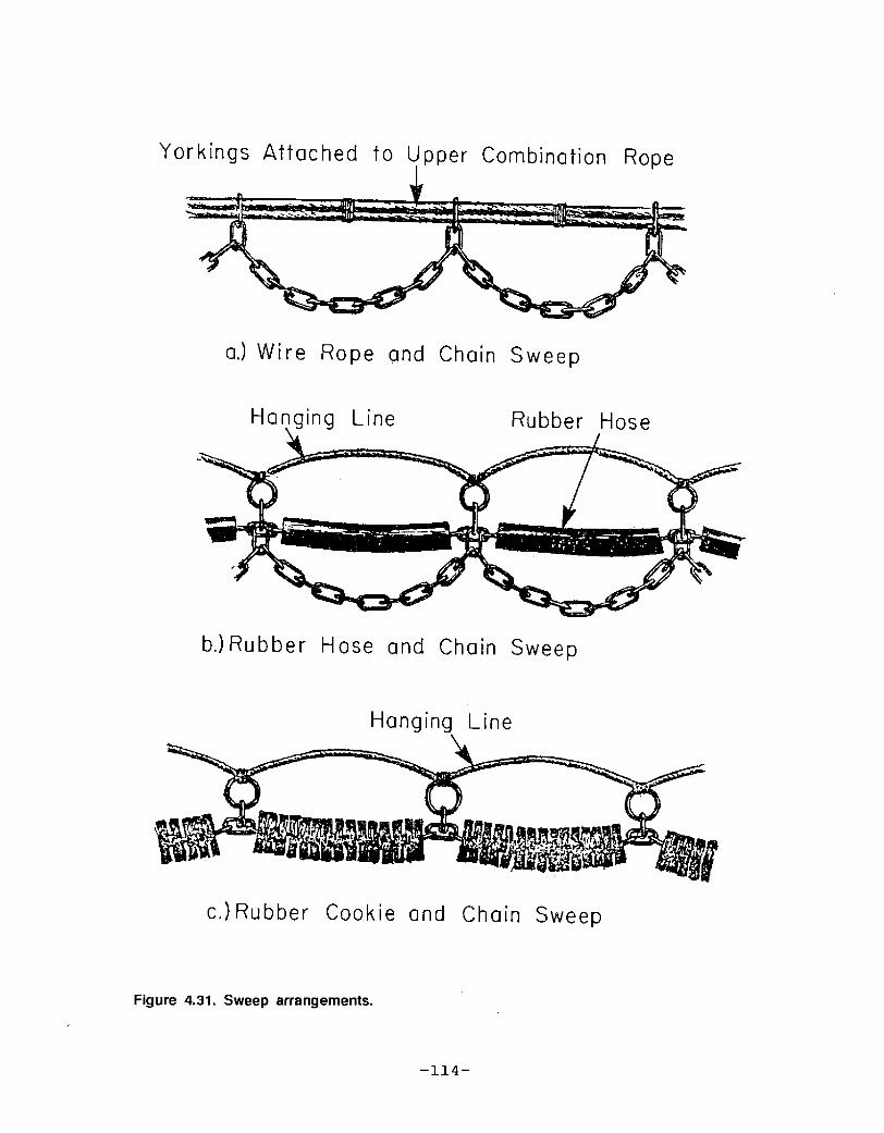
Yorkings Attached fo Upper Combination Rope
a.! Wire Rope and Chain Sweep
Hanging Line
b.! Rubber Hose and Chain Sweep
Hanging Line
c.! Rubber Cookie and Chain Sweep
-114-
Figure 4.31. Sweep arrangements.
R

two together. The quarters are then positioned. and stopped.in place. If a chain sweep is being used, the hanging linewill be attached by closing split links. If heavy rollersare used, the hanging line will be seized to a fishingline, or to rings for a zipper chain. In these cases, therings or chain links must be "cross seized" stopped acrossthe rope! in order to keep the chain straight and provide afirm seizing.
To seize on a ring to the hanging line in this manner, apiece of twine about 2 meters in length is used. The endsare passed through the ring and back out through the bightof the twine forming a cow hitch. The rope is then placedon the ring, the twine taken over the rope and two halfhitches made on the opposite side of the ring. The twineis then taken over the rope again to the other side, andtwo more half hitches formed. This procedure is repeateduntil about 25 cm of the doubled twine remains. The endsare now separated, one being passed one way and the otherthe opposite way between the hanging line and the chainseveral times, pulling it taut. The work is completed bytying two square knots, one on top of the other.
4.8.2 Floats
The purpose of the floats or "cans"! is to provide initialflotation to raise the headline of the net and so providean effective open mouth area. In addition to the verticalflotation force on the headline, the floats cause drag vhentowing, which tends to pull the headline back and reducethe headline height. This drag effect increases markedlywith the speed at vhich the net is toved through the vaterso that the number of floats to be used in any particularcase requires a rather delicate balance betveen thebenefits of buoyancy and the detriment of drag.
Standard modern floats used vith travls are approximately20.3 cm diameter spheres constructed from aluminum or hardplastic and have about 3.2 kg of positive buoyancy. Thesematerials have proved effective in resisting the crushingpressures exerted by the depths in vhich trawls work. Atthe same time, they are sturdy enough to resist the heavytreatment, abrasion and impact forces to which they aresubjected when the net is being set and brought aboard.
4.8.3 Extension pieces
In some fisheries, it is common to extend the overalllength of the net through the use of extension pieces.These are placed betveen the bellies and the cod-end, and
-115-

Hanging Line Zipper Chain Roller Chains
Hanging Line
Figure 4.32. Roller sweeps.
Roller Chains

are usually made in two sections, one for the top half andone for the bottom half of the net and then laced togetherin the usual manner when the net is put together.
Extension pieces may be shaped i.e., have a taper! betweenthe belly and the cod-end, especially in the case of largernets, or may alternatively be square pieces of webbing ofeither the same or a different mesh size from the bellies.Their length will vary according to the fishery and therequirements of individual net designs or skippers.
A typical extension piece for the 3/4 Yankee net would havea depth of 50 meshes and would taper from 40 meshes inwidth at the belly equal to the belly dimension! to 30meshes at the cod-end half the cod-end circumference!.The taper of the two sections upper and lower! required tomake the complete extension tube is calculated with thesame formulas presented previously. The extension sectiondimensions are 40 x 30 x 50 deep.
The cut is:
1040 � 30WE � NE
The taper is:
2 x C 2 x 5 10 5B
4 �B/1P! / 1 �B/2P!D � C 50 -5 45 9P
A good extension for the model Yankee trawl net is 9 x9 x 10, with the resulting taper being all points.
4.8.4 The cod-end
The cod-end is made of extra heavy twine of a suitable meshsize. The size of the mesh must conform with anyregulations which are in force to permit the escape ofundersized fish. A typical inshore ground fishery uses amesh size in the cod-end of. 7.6 cm. For a 7.6 cm meshcod-end, the standard size is 60 meshes around by 50 mesheslong. As the extension sections are made 30 meshes wide atthe narrow end, the 30 meshes of the cod-end can be sewndirectly to the narrow end of the extension.
The tail end of the cod-end is closed up by a cod-end rope.To take this rope, rings often two inches in diameter are
-117-

knitted on, one ring to two meshes. A rope, often 1.3 cm,is then passed through the rings and tied with one of theregular cod-end knots, or a cod-end tripper.
In some cases, a liner of much smaller mesh may be fittedinside the cod-end in order to retain fish or other sealife which would normally pass freely through the cod-endmesh. The liner is usually of cylindrical shape and sewndirectly to the inside of the webbing, forming the cod-endat its forward end. The length of the liner should beabout 30.5 cm greater than the cod-end itself. When tying,the liner should be brought out through the cod-endopening, and the rope in its rings tied tightly around itso that a "tail" remains outside the net.
4.8.5 Working and strengthening ropes
Dependingthe trawl,these mayrope, and
on the particular technique being used to fishvarious working ropes are necessary. Typically,
include: quarter ropes, splitting strap, bullgore lines.
The splitting strap is always fitted. It has two mainpurposes. First it allows easy splitting of the catch whennecessary; secondly, in the case of a bad tear up when bothbellies are tarn off, the cod-end can be saved.
The splitting strap is placed some six feet ahead of thecod-end rope. Rings may be stopped to the twine everyother mesh around the cod-end, or beckets seized on only atthe gore seams. A rope �.6 cm to 2.5 cm in diameter! isthen passed around the bag through the rings or beckets andspliced or tied together Figure 4.33!. A bullrope �.6 cmto 2.5 cm! is either tied or spliced into the splittingstrap on the upper side of the net, to be taken loosely to,and tied at, the headrope.
When fishing on an abrasive bottom, the weight of fishtrapped in the cod-end causes the twine in contact with thebottom to wear out rapidly due to the chafing effect. Theharder the bottom, the more important it is to provide"chafing gear" to protect the cod-end webbing. A commontechnique is to use short lengths of unlaid synthetic ropetied in at each knot of the underside of the cod-end.These short lengths are tied in using a cow hitch with thefree ends unraveled to provide an extended wearing surface.These wear out with the abrasion and must be replaced asnecessary.

Quarter ropes are used to lift the sweep and headrope thenet mouth! aboard a vessel which uses this technique forhandling the net. They are connected to the sweep atlocations which are dependent on the positioning of thequarter rope blocks aboard the vessel. Usually, they arepositioned between 1.5 and 3 m each side of the center ofthe sweep.
Each quarter rope is taken from its fastening at the sweeprope very loosely around the outside of the net, through abecket usually a 10 cm ring stopped to the headrope thesame distance each side of its center! at the headrope, andmade fast at the wing.
Connection of the quarter rope to the sweep is made by useof a quarter rope cup or bucket. These buckets are coneshaped and sized to fit the rope being used. The quarterrope is passed through the small end and knotted so that itjams when pulled tight, to avoid its chafing on the bottom.The bucket is attached by a pear link to a swivel, whichis, in turn, stopped or shackled to the sweep.
When large or heavy catches in the net are anticipated, andin the case of some heavily rigged gear operating underrigorous conditions, strengthening ropes are fastened tothe net to help avoid distortion and the carrying away oftwine and whole parts of the net.
The most common is a gore line which is fastened along thelaceage, or gore, to take the longitudinal strains at thisseam. A gore line usually runs from the forward end of thewings along the laceage to the rear of the cod-end. It isparticularly important in the case of nets which aredesigned for use with three bridles, where much of thetowing strain is taken along the laceage.
Other longitudinal strengthening ropes may be used asnecessary in the top and bottom panels of the net torelieve the strain on the webbing and allow it to take up anatural, unstrained shape. In order to prevent a netbursting, circumferential strengthening ropes may be used,especially in nets which are used to catch fish in bulk.In some cases, the arrangement of longitudinal andcircumferential strengthening ropes may be quitesophisticated.
-119-

Bull Rope
Splitting S
Rein forcing
Figure 4.33. Cod-end rigging.
4.9 References
Garner, J. 1962. How to make and set nets or thetechnology of netting. Fishing News Books Ltd. 95pps ~
Garner, J. 1973. Modern inshore fishing gear, rigging andmending. Fishing News Books, Ltd. 69 pps.
Garner, J. 1977. Modern deep sea trawling gear. FishingNews Books, Ltd. 83 pps.
Fridman, A.L., M.M. Rogenshtein and V.N. Lukashov. 1979.Design and testing of trawls. Translated from Russianand published for National Marine Fisheries Service,NOAA and U.S. Dept. of Commerce. 212 pps.
Kostyunin, Y.N. 1971. Trawls and trawling. Translatedfrom Russian and published for U.S. Dept. of Commerce,Virginia. 144 pps.
Sainsbury, J.C. 1971. Commercial fishing methods, anintroduction to vessels and gear. Fishing News Books,Ltd. 119 pps.
Von Brandt, A. 1984. Fish catching methods of the world.Fishing News Book, Ltd. 418 pps.
-121-


BASIC NET DESIGN:
FYKE NETS

Page
5.1 Introduction 0 ~ ~ 0 ~ 0 t t 4 ~ 125
5.2 Materials and Construction 125
5.3 List of Materials for Fyke Net................... 126
5.4 Fyke Net Plan- 126
5.5 Construction Details ....... ~ ~ 1 ~ ~ 0 127
129
129
5.6 References......... 131
5.5.1
5.5.2
5.5.3
5.5.4
5.5.5
CHAPTER 5
BASIC NET DESIGN: FYKE NETS
Hoops .-Funnels
Barrel .
Leader
Wings
127
127
128

BASIC NET DESIGN: FYKE NETS
5.1 Introduction
Fyke nets are traps made from netting, which are placedin bays, rivers and other inshore areas. There are manyvariations in the design, size and fishing methods of thefyke net Figure 5.1!.
The fyke net originated in Europe and was introduced tothe East Coast of the USA in the late 19th century.Although proven effective at capturing eels, it has beenmodified to effectively capture flounders, white perch, seabass, cod, and bluefish.
Fykes can be fished at water depths of 10 to 50 ft.Similar to other passive fishing gears, fykes arefuel-efficient, and easily managed and modified. The catchusually will remain alive and in good condition untilextracted from the net.
5.2 Materials and Construction
Fyke nets have three distinct parts: leader, barrel,and two wings optional!. The leader and wings act toguide fish into the main body, or barrel. The barrel isessentially a hoop net constructed of frames covered withweb netting or wire mesh. Fish pass through funnel shapedthroats or non-return devices in the barrel and are trappedin the last section.
Figure 5.1. Typical arrangement of a coastai fyke net.
-125-

5.3 List Of Materials for Fyke Net
4 hoops with indicated measurements fiberglass or other!webbing: 136 x 168 D, 5.0 cm x 1.6 mm for the barrelwebbing: 240 x 46 D, 5.0 cm x 1.6 mm for wings and leader.
5.4 Fyke Net Plan
The details of the fyke net plan are illustrated in Figure5.2.
2020
136m
24
20
25 Dee
Figore 5.2. Fyke net plan.
-126-
Sewing twine: 1.6 mmLines and anchors to set lead'erLine and anchor to set end of fyke
33D 2 23D
2 Sets
F Unnel s.

5.5 Construction Details
5.5.1 Hoops
The net plan presented in this chapter is for a smallfour-hoop fyke net. Fiberglass hoops can be purchased in thediameters indicated in Table 5.1. Since fiberglass tends tosplinter, it is recommended that each hoop be wrapped withheavy tape. Other materials such as galvanized steel, orwood bent in circular patterns, can be substituted.
Table 5.1. Fyke net hoop characteristics.
Hoo Diameter Circumference Han in
5.5.2 Funnels
Two funnels need to be constructed with the indicatedmeasurements Figure 5.3j. These will be placed in hoops ¹1and ¹3. The funnels are laced to the hoop with the samehanging ratio as the barrel.
25 Dee
2020
Figure 5.3. Funnel cutting plan.
-127-
¹1¹2¹3¹4
107 cm
91.4
76.2
76.2
336 cm
287 cm
239 cm
239 cm
1 mesh per 2.5 cm1 mesh per 2.2 cm1 mesh per 1.8 cm1 mesh per 1.8 cm

Sew the two halves together at the all bars tapers toform the funnels, then sew onto the bare hoops.
5.5.3 Barrel
The fyke barrel is constructed entirely from a singlepiece of 50 cm mesh webbing that is rolled into a cylinderaround hoops, and laced at the seam. There are 136 meshesalong the mouth and 120 meshes in depth. Four all barstapers are cut into the last section �5 meshes deep! toterminate in 20 meshes for each half of the cod-end Figure
5.4! . 136 30 Deep30 Deep
30 Deep
25 Deep
24 20 24 20
Figure 5.4. Cutting plan for barrel.
-128-

The fyke barrel is made by sewing the section to thefiberglass hoops. These hoops are placed every 30 meshes.The meshes are laced onto the hoops according to the hoopcircumference. Once the barrel is attached to the hoops,the seam is sewn in the barrel section.
5.5.4 Leader
The leader is made from a single sheet of 5 cm webbing240 meshes wide and 22 meshes deep.
240
Figure 5.5. Cutting plan for the leader.
The leader is attached to a floatline of 1.0 cm braidedpolypropylene line with a hanging ratio of 0.5, meaningthat the 240 mesh piece of webbing �2 m! will provide a6 m leader. The leadline is similarly attached using a 1.0cm braided polypropylene line with a 50 gram lead spacedevery 30.0. The leader is then attached in the middle ofthe first hoop.
5.5.5 Wings
The wings are formed from a single sheet of 5 cm webbingmeasuring 240 meshes wide and 23 meshes deep.
240
Figure 5.6. Cutting plan for the ~ings.
-129-

Mesh
19 B ars
SiderSider
19
Mesh
Figure 5.7. Detailed cutting plan for diamond shaped hole.
After attachment to the hoop, there will be a slightoverhand along the top. This can be sewn into the hoop orleft to form a canopy over the hoop to prevent escaping.
-130-
The wings willdiamond shapedbars down to a
cut 19 bars to
starting point
be secured to the first hoop by cutting ahole in the center of the webbing. Cut 19sider, then cut 19 bars to a pickup, and thenthe opposite sider and back 19 bars to the Figure 5.7! .

5.6 References
Commercial fishing gear of the United States. Bureau ofthe Interior. Fish and Wildlife Service. Washington25, D.C. 61 pps.
FAO Catalogue of small-scale fishing gear. 2nd edition1987. Fishing News Ltd. 224 pps.
Visel, T. and L. Stewart. 1987. A guide to theconstruction of fyke nets. Sea Grant PublicationCT-S6-87-08. The University of Connecticut. 16 pps.
-131-


CHAPTER 6
ET MENDING PATCHING
AND SPEC IALIZED TRAWWL REPAIR TEC HNI QUES

CHAPTER 6
NET MENDING, PATCHING, AND SPECIALIZED
TRAWL REPAIR TECHNIQUES
Page
6.1 Net Mending ..... ~ ~ e ~ ~ ~ ~ 1 35
6.1.1 Mending simple tears and holes .6.1.2 Trimming and mending holes and tears .......
135
138
6.2 Net Patching ....... ~ ~ 0 ~ ~ ' ~ ' ~ ' ~ ~ ~ ~ ~ ~ ~ ~ ~ 143
6.3 Specialized Trawl Net Mending TechniqUes 149
6.3. 1
6.3.2~ ~ ~ t ~ ~ ~ ~ 1 49
6.3.3
6.3.4bars ...
6.4 References . ~ 0 0 ~ ~ ~ ~ ~ ~ ~ 159
6.2. 1
6.2.2
6.2.3
6.2.4
A simple patch in a rectangular hole ..Patching a non-rectangular hole . ~ .....Using a patch of different mesh size ..Lacing for temporary repair
Mending wings reinforced with dog earsMending wings reinforced with dog ears
and a full mesh of double twine ......Mending wings reinforced with straightJoining wing sections ..
143
146
147
149
150
155
159

NET MENDING, PATCHING AND SPECIALIZEDTRAWL REPAIR TECHNIQUES
6.1 Net Mending
6.1.1 Mending simple tears and holes
The simplest mending operation is the repair of tears wheresuccessive horizontal or vertical bars are cut.
In a piece of webbing, each knot always has four barsleading to it, never three or two unless it is on the edgeof the webbing, and never five under any circumstances.When mending, a starting knot is tied to an existing knotand the twine on the needle must be used to form the fourthbar to that knot. To begin mending, therefore, thestarting knot must be made over a knot which already hasthree bars leading to it. Similarly, the finishing knotmust also be made over a knot which has three bars leadingto it. Such existing knots in a piece of webbing which isdamaged are called "three � leggers".
The simplest tear is shown in Figure 6.1a. Here the twothree-leggers are at the same height in the webbing and thestarting knot may be made at either �! or �!. To startat �!, a double sheet bend or starting pickup knot is madearound the three-legger. This tear may be mended workingfrom left to right in a similar fashion to sewing twopieces of webbing together. First a pickup knot is made onthe nearest mesh the lower half mesh! at a! in the usualmanner with the length of the bar being adjusted by eye.This is followed by a pickup knot on the next mesh theupper half mesh! at b! in the usual manner, the length ofthe bar being adjusted by eye. This procedure is nowcontinued until the final pickup knot on the mesh at. g!has been formed. The repair is completed by forming adouble sheet bend at the three-legger �! as a finishingknot. Note that in this case where the starting and endingthree-leggers are at the same height, the mending couldhave been started at �! and, working from right to left,finished at �!. In the Figure 6.1b, where thethree-leggers are at different heights, a start is made onthe upper three-legger at �!. Working from right to left,successive pickup knots are formed at a!, b!, ' c!, d!, e!, and f!, followed by the finishing knot around thethree-legger at �!.
A simple vertical tear which has three-leggers at �! and�! is shown in Figure 6.2. The repair is started by
-135-

forming a double sheet bend at the three-legger �!; thisis followed by making a right sider knot at a!, a leftsider knot at b!, and so on until the final right siderknot is completed at e!. The repair is completed by a
Figure 6.1. Simple horizontal tears.
Figure 6.2. Simple verticaltear. The starting three-legger is at1. Thefinishingthree-legger is at 2.
� 136-
a! The three leggers at1 and 2 are at the
same height
b! The three leggers at1 and 2 are at
different heights

double sheet bend around the three-legger �!. The missingbars have now been replaced and the vertical tear ismended.
A rectangular hole having a depth and width equal to twowhole meshes plus a half mesh is shown in Figure 6.3a. Thehole therefore, has two sides made of meshes pickups!, twosides of points siders! and two diagonally oppositethree-leggers at �! and �!. The procedure for mendingthis hole is shown in Figure 6.3b, and is described asfollows. A double sheet bend or starting pickup knot istied onto the starting three-legger �!, then a singlesheet bend or pickup knot on the upper meshes a!, to aleft sider knot b!, a right sider knot c!, a single sheetbend or pickup knot to the lower meshes d!,- and finally adouble sheet bend or finishing pickup knot is tied on tothe finishing three-legger �!.
Figure 6.3. a! The repair on a simple rectangular hole is started at the three-legger 1 andfinished at the three-legger 2. b! The procedure for mending a simplerectangular hole .
-137-

6.1.2 Trimming and mending of holes and tears
In the previous cases, it has been assumed that the tear orhole has already been prepared for mending, so that thetwineperson has only to knit in the required meshes. Inpractice, this is seldom the case, and it is necessary totrim a hole before beginning to work with the needle.
The process of trimming a hole requires the cutting out ofunwanted free ends of bars and some existing bars in orderto provide starting and finishing three-leggers, and alogical mending sequence in between.
Two initial rules are important:
1. Knots in pickups or meshes should be removedentirely.
2. The knots in a sider cannot be cut out; if they are,the webbing will separate. The ends of sider knotsshould be left at least 1 cm long so that they donot become untied.
To begin trimming a hole, the webbing should be laid outand the run of the twine identified. Trimming should bestarted at the very top of the hole and proceed down oneside of the hole. A three-legger must be left to start themending. All the remaining three-leggers must be cut outby cutting around the edge of the hole. In places wherethree-leggers come together, a cut is made between them andboth are eliminated. This is continued until the bottom ofthe hole is reached. Cutting is then begun next to the topthree-legger and down the other side of the hole until thebottom is reached again. This will leave a three-legger inthe bottom of the hole on which to finish.
To recognize a three-legger, the knot should be picked upon one finger and the parts of the twine that connectdirectly to the knot should be counted. Only the partsthat connect with other knots should be counted; an endwhich is hanging free is not counted as a bar. Existingpickups and siders at the edges of the hole should be leftas they are, since they will fit naturally into the mendingpattern.
To do a proper job of trimming and mending, the followingrules must be known and followed:
-138-

1. Nake sure the three-legger is left in a positionthat will allow you to get to a sider on theopposite side of the hole.
2. The only time you can go to a sider is when a squaremesh is formed by making a single bar.
3. Every time a sider is reached you then look for apickup. If the pickup is there it must be taken;you will then find that another pickup will bedirectly opposite the one you have just taken. Thisis your next move. However, if after you make thesider a pickup is not there, you must turn and goback across the hole until you reach a sider. Thisprocedure is followed until the hole is finished.
4. You cannot go from one sider to another sider on thesame side of the hole, but you can go from sider tosider providing they are opposite each other.
5. You cannot make a pickup on a sider.
6. When starting to mend a hole on the left hand side,the needle is passed up through the mesh and theknot is tied. Whereas, moving from right to left,the needle is passed down through the mesh. Thismust be done in order to keep the meshes frombecoming twisted. This applies only to aright-handed person. A left-handed person would dothe opposite.
The process of trimming a simple tear, based on the aboveprocedures, is illustrated in Figure 6.4a. The brokenlines indicate bars of meshes removed during trimming. Thecrosses X! indicate cuts made during trimming operation.When mending the hole Figure 6.4b!, a start is made at �!and the first row of meshes worked from right to left untilthe sider at a! is taken. The next step is to the pickupat b!, following which a row of meshes is knitted fromleft to right until the opposite sider at c! is taken.Here, the bottom pickup d! is available and must be taken,followed by another row from right to left until theopposite sider at e! is taken. Now the bottom pickup f!is available and sewing proceeds from left to right untilthe finishing three-legger �! is reached.
The procedure for trimming and mending a simple diagonaltear is illustrated in Figure 6.5a. Start at the top ofthe tear; a starting three-legger is available at �!.Working down the left side of the hole, remove all the
� 139�

Mending
Trimming
Figure 6.4. a! Trimming and b! mending a hole.
three-leggers by cutting at b! and c! . Now work down theright side of the hole and remove the three-leggers bycutting at d! and e!. This will leave a finishingthree-legger at �!. The hole, when trimmed, will appearas in Figure 6.5b. The mending of this trimmed diagonaltear is straight forward. A start is made at thethree-legger �!, followed by a natural progression to thesider a!, lower pickup b!, upper pickup c!, sider d!,opposite sider e!, lower pickup f!, upper pickup g!,sider h!, to the finishing three-legger �!.
The trimming and mending of a more complicated diagonaltear is illustrated in Figure 6.6a. In this case, a numberof meshes of twine are missing entirely. The missing barsare shown by the blank spaces, and the final trimmed holeby the heavy lines. To trim the hole, a start is made atthe top, a starting three-legger is available at �!.Working down the left side of the hole, bars are cut at b!, c!, and d! to eliminate three � leggers. On the rightside of the hole, three-leggers are eliminated by cuttingbars at e!, f!, g!, and h! until the finishingthree-legger remains at �!.
The mending of the properly trimmed hole is slightly moredifficult than the previous example. The final hole isshown in heavy lines Figure 6.6b!. Starting at the
� 140�

Trimming Mending
Figure 6.5. a! Trimming a diagonal tear and b! mending a diagonal tear.
Often a hole will appear in a V-shape. In this case, it isusually necessary to mend the hole in two stages, startingat the top of each leg of the V in turn. First the smallerof the tears is trimmed and mended as far as possible.Then the remaining hole is trimmed and mended in the usualfashion. Note that when trimming the remaining hole, itmay be necessary to cut bars attached to the new twineknitted in when mending the first tear. This procedure
-141�
three-legger �!, the procedure is to sider a!, to lowerpickup b!, to upper pickup c!, to sider d! to sider e!,knit half mesh to upper pickup f!, to sider g!, knit leftto sider h!, knit right to upper pickup j!, half mesh topickup k!, to sider l!, knit left to sider m!, to lowerpickup n!, sew right to lower pickups o!, p!, knit rightto upper pickup q!, to sider r!, knit left to sider s!,to lower pickup t!, and sew right to finishingthree-legger �!.

Trimming
Mending
Figure 6.6. a! Trimming and b! mending a more complicated diagonal tear.
-142-

avoids the cutting away and replacement by mending of alarge part of the V-shaped flap of webbing which would benecessary if the hole were trimmed for mending in oneoperation. Often, when holes of this type are large andspread in several directions, mending may be donesimultaneously by two or more twinepersons working downtowards one another.
The tear in the shape of a V is shown in Figure 6.7a. Thesmall tear on the left is mended first. The startingthree-legger is at �! and the left side of the tear istrimmed by cutting, as shown, to remove the three-leggers.Starting at the three-legger �!, mending proceeds to theright sider a!, to the left sider b!, to the lower pickup c!, to the upper pickup d!, to the right sider e!, tothe left sider f!, and to the upper pickup g! Figure6.7b!. At this point there is no pickup or sider availableto be taken, and the mending stops. The shape of theremaining hole is now as shown in Figure 6.7c. Theremaining hole is now trimmed as shown, to permit a newstart to mending at the three-legger �!, with thefinishing three-legger at �!. The shape of the finaltrimmed hole is as shown in Figure 6.7d. Starting at thethree-legger �!, mending proceeds to the pickup h!, tothe right sider j!, knit left to the left sider k!, thenknit right to the right sider e!, knit left to the upperpickups m! and n!, and to the left sider g!, knit rightto the right sider p!, take the lower pickups q! and r!,to the upper pickup s!, to the left sider t!, to theright sider u!, and finally to the three-legger �!.
6.2 Net Patching
When a hole is so large that an excessive amount of mendingwould be needed for repair, it is preferable to replace thedamaged portion with a patch of webbing having the samemesh size. In order to avoid complicating the work, theprepared hole and the patch should be square or rectangularin shape, having dimensions in length and depth equal to awhole number of meshes. This avoids the leaving ofthree-leggers in the hole and in the patch! and enablesthe work to be done by straight sewing and sidering.
6.2.1 A simple patch in a rectangular hole
The damaged section of webbing is removed by cuttinghorizontally below a row of pickups at the top and above arow of pickups at the bottom, being sure that a wholenumber of meshes are removed. This is illustrated inFigure 6.8a, where a length of three meshes has been cut
-143�

Figure S.7. Trimming and mending a v-tear in two steps.
a. V tear
c, trim o ther side
-144-
b. mend one side
d, mend other side

out the existing pickup knots are then removed!. This isfollowed by a vertical cut on the left hand edge to theright of a line of points siders! and a vertical cut onthe right, to the left of a series of points siders!,again ensuring that a whole number of meshes has beenremoved in this manner the siders are, of course, left "asis"! .
patch3 meshes
~ wide~
patch2 meshes
hole3 meshes
removeddeep
~hole~4 meshes
removed
Figure 6.8. a! Trimming for a patch.
A suitable patch for the repair is then cut out of a squarepiece of webbing. This patch must again have length anddepth equal to a whole number of meshes, but be one meshless in each dimension. The patch is put in by sewing andsidering along each edge in turn as shown by Figure 6.8b inone continuous operation, two twinepersons may worktogether. One twineperson should start on the top left asshown in Figure 6.8b, and sew along the top and sider alongthe right side to end at d!. The other twineperson would

also start at �! or alternatively at d!! and work alongthe left and bottom sides of the patch. A start may bemade at any corner. Here, the starting point is on thepickup �! at the top left corner. The twineperson startswith a double sheet bend at �! and then sews to the rightuntil the pickup at a! is taken; then proceeds to theright sider b! and siders down the right side until thefinal sider at c! is taken; then to the lower pickup at d!, sewing to the left until e! is reached, then to thefirst left sider at f!, and siders up to g!. The patchis completed by a finishing knot at �!, the startingpoint. Note that �! becomes a three-legger once thestarting knot has been made.!
Figure 6.8. b! Sewing and sidering for a patch.
6.2.2 Patching a non-rectangular hole
It is not essential that all holes and patches arerectangular, although the operation should always involvehorizontal all meshes! and vertical all points! cuts for
-146-

both the hole and the patch. Commonly, part of a largehole may be cut out and. joining in the patch commenced.When the operation has proceeded as far as practicable,then a further section of hole and patch can be cut to fit.The patch can be any shape so long as each corner turnedduring cutting out the hole and patch is a right angle.
Figure 6 ' 9 shows a typical non-rectangular patch fitted toan appropriate hole; dimensions equal to a whole number ofmeshes for each length and depth are illustrated, andjoining up the patch can be accomplished by either onecontinuous operation or by several twinepersons workingtogether if a very large patch is involved.
Figure 6.9. Fitting a non-rectangular patch.
6.2.3 Using a patch of different mesh size
Although normally the webbing used for patching should beof the same mesh size as the damaged web, sometimes theonly material available will be of a different mesh size.
� 147-

In such a case, it is still possible to put in a patch inorder to effect a temporary repair. However, on the firstpossible occasion, such a patch should be removed andreplaced by a patch of the correct mesh size. This istermed a "soft patch."
In such a case, measurement of the length and depth is madeby using the stretched mesh length of each side of the holeagainst the stretched mesh length of the corresponding sideof the web being used as the patch. Obviously, the meshesof the patch cannot be lined up with those of the hole.
Knots are tied only in the side of the join that has thelarger mesh size. The twine is simply passed behind theknots along the edge of the webbing having the smallermesh, as shown in Figure 6.l0.
Figure 6.10. Patching with webbing of a smaller size.
-148-

6.2.4 Lacing for temporary repair
Lacing is used to make a temporary repair when it isnecessary to make a net available for use as quickly aspossible. It is usually pulled out as soon as anopportunity is available, and a proper repair made. [&enlacing, the twine is passed behind the knots on each sideof the tear and fastened with a double hitch on one side ofthe tear only, about 15.2 cm to 30.5 cm apart. It is mostimportant, when lacing, to leave sufficient slack in themending twine so that some natural adjustment can takeplace when strain is placed on the laced-up section of theweb.
6.3 Specialized Trawl Net Mending Techniques
The repair of interior tears and holes in the webbing oftrawl net sections is accomplished according to theprocedures outlined in the previous sections. Trawl netwings are often tom off the straight bar of the insideedge along the mouth frame. In many cases, the wings arereinforced with dog ears or straight bars plus a full mesh.If wings become damaged so that it is necessary to repairthem, this may be done by mending or by joining in a newsection of wing. Because straight bars and dog ears areinvolved, such mending requires procedures beyond thosenormally used for the usual mending and patching.
6.3.1 Mending wings reinforced with dog ears
This is necessary when the dog ears which are knitteddirectly on to the straight bars with double twine aredamaged. Two cases arise.
The first occurs when a length of the wing which does notinvolve the wide end is damaged at the edge. Here it ispossible to trim the hole and mend from the wide end towardthe narrow end, as a starting point is available on aremaining three-legger. The procedure is shown in Figure6.11. The steps are as follows, using a needle filled withsingle twine: starting at the three-legger a!, half meshesare knitted downward to b!, then to sider c!, and thenhalf meshes are knitted back upward to the pickup d!.From d!, a four bar length look of twine is made back to asecond pickup knot at d!, then a three bar loop of twineto the pickup e! completes the doubled dog ear. Neshesare then knitted downward to the sider f! and back upwardto the pickup g!, where a four bar look is formed back tothe same knot at g! followed by a three bar loop to h! tocomplete the second doubled dog ear. Knitting is
-149-

continued to j! and back to k! where again a four barloop and a three bar loop are formed to end the third dogear at �!. Mending is completed by the straight bar to thethree-legger at m!.
If the damage extends into the wide end so that no dog earsremain, then it is necessary to build up the missing twineby working from the narrow end toward the wide end. Thisis known as "backscuttling" and the procedure is shown inFigure 6.12. This method, as shown in the sketch, is usedin particular when the bunt end wide end! is tom out, sothat it is necessary to work from the narrow end toward thewide end. Some twinepersons prefer to use the method whenmending dog ears are at the center of the wing. The stepsare as follows, using a needle filled with single twine: astarting knot is made at a!, the three-legger whichincludes one bar of the doubled dog ear. A one bar lengthof twine is adjusted, followed by a four bar loop, which isthe full round of a single part of twine for the first dogear; the four bar round is ended with a pickup knot at b!.
A second round of single twine is then made with a secondpickup knot at b! to complete the first dog ear of doubledtwine. From b! the twineperson proceeds to c!, with asider, and then up to a pickup knot at d! on the doubledmesh dog ear! formed previously. From d!, the single barand the two rounds to form the second dog ear are made,with pickup knots at e!. From e!, continuing as beforebrings us back to the pickup knot at g! on the second dogear formed. From g!, the procedure is repeated once moreto form the third doubled dog ear, ending at the pickup h!. From h!, normal knitting takes us to the sider j!at the wide end of the wing. From j!, the twinepersonknits the end row of the wing up to the pickup k!. Therepair is completed by finishing on the three-legger at
�!- 6.3.2 Mending wings reinforced with dog ears and a full meshof double twine
If the wing is reinforced with a full mesh of doubled twineto which dog ears are added, then the procedures involvedare more complicated and involve the use of two needles,one filled with doubled twine, the other with a singlepart. The same two cases arise as before.
When the wide end of the wing is not damaged, then it ispossible to work toward the narrow end; this procedure isshown in Figure 6.13. It involves the use of two needles,one filled with single twine shown by single lines! the
-150-

BUNTEND
ON
EGGER
END
Figure 6.14. Mending wings reinforced with dog ears.
DOOR
F l NlSH ON
THREE LEGGER BUNT END
Figure 6.12. Backscuttling.
-151-

other filled with doubled twine shown by two lines!.Start at the three-legger a! using the needle filled withsingle twine. The twineperson knits across to b! at whichpoint a three bar length of twine is made which includes anoverhand knot c! which acts as a dummy sider for latermending with the doubled twine, when it serves to anchorthe knot. The twineperson then proceeds across to thesider d! and back to e!. Here, another three bar loop ismade, including the dummy overhand knot at f!. Theprocedure is continued, losing one mesh for each completemesh knitted on until the final double bar is made,including a dummy sider p! to end at the three-legger q!.Mending of the single twine is now complete. Using theneedle filled with double twine, the twineperson now beginsat the three-legger A! and knits on the double mesh plusthe dog ear, as has been explained previously in thechapter on trawl construction.
For simplicity of explanation, the above technique involvedcompleting mending with single twine before beginning withthe double twine. In practice, the twineperson willusually find it more convenient, especially if the damageis considerable, to mend with single twine to form thedoubled mesh and dog ears on the partially completedrepair. By alternating single and double twine, thetwineperson can then move along the edge of the twine,completing the mending as he/she progresses.
If the wide end of the wing is missing at the edge, then itis necessary to begin work on the remaining twine of thenarrow end and work toward the wide end. This is shown inFigure 6.14. It involves the use of two needles usedalternately, one filled with single twine, the other withdouble twine. The steps for mending twine are as follows:
Single Twine: start at three-legger a! and knit to sider b! including an overhand knot as a dummysider to anchor double twine later!; dropthe needle.
Double Twine: start at three-legger A! and form a five barloop back to one bar with a pickup knot asshown, then to dummy sider in the singletwine, then to B!; drop the needle.
Single Twine: from b! go to c! on the double twine formedin previous step. Then form three bar loopwhich includes the dummy sider as shown, andacross to d!; drop the needle.
-152-

LULU
Z ~LU
0 ~Q Z
I�
~ Z4 p
E EO
C!
C!
Q.C!
CK
~ oZZ
pa0 Z0
<f p Z 0Z
Figure 6.13. Mending wings with two needles straight dog ears!.
-153-

z 0
p 0 m rnO rn
Figure 6.14. Mending wings with two needles backscuttled dog ears!.
-154-

Double Twine: from B! form a five bar loop to the one barwith a pickup knot as shown, then to thedummy sider on the single twine and back to C!; drop the needle.
Single Twine: from d! knit to e! then form three barsincluding the dummy sider, and go back to f!; drop the needle.
from C! form the five bar loop to the onebar with a pickup knot as shown, then to thesingle twine dummy sider, and back to D!;drop the needle.
Double Twine:
Single Twine: from f! knit to g!, make the three bar loopincluding dummy sider and back to h!; dropthe needle.
Double Twine: from D! form five bar loop then to singletwine dummy sider and back to E!; drop theneedle.
Single Twine: from h! knit to j!, form three bar loopincluding overhand knot and knit back to endon the three-legger k!. These actions formthe single twine part of the wide end of thewing.
Double Twine: from E! make the five .bar loop, then to thesingle twine dummy sider and back to F!,then finish on the three-legger of doubletwine at its correct position on the wing.
6.3.3 Mending wings reinforced with straight bars
Depending on the way a hole is running, it may be mended byworking from the narrow end door end! of the wing towardthe wide end, or from the wide end toward the narrow end.
-155-
The procedure when working from the wide end toward thenarrow end, which is possible if the wide end is notdamaged is shown in Figure 6.15. In this case, batings areinvolved because a mesh is lost in length with each twostraight bars. The hole resulting from the damage istrimmed to give the shape shown. Run of twine is from topto bottom. Mending is begun with a starting knot at a!and half meshes are knitted down to b!, and then to thesider c!. From c!, half meshes are knitted across to d!; at d! a loop equal to three bar lengths is made asshown, ending in a pickup knot at e! formed around the

three parts of twine a selvedge mesh!. From e!, meshesare knitted across to f!, then to the sider g! andfinally to the knot at h!. In forming the pickup knot at h!, both mesh and loop are taken up in the needle and theknot tied around the four parts of twine forming abating!. From h!, another loop equal to three bar lengthsis made and the pickup knot tied around the three parts oftwine, as before, at j!. A mesh is knitted to k! andthen to the sider l! and across to m! where the fourparts of twine are again included in the knot. A furtherthree bar length loop is formed with the pickup knot at n!made around the three parts. Mending is completed byforming the bar from n! to o!; at o! the final knot istied around the four parts of twine.
W1DE END
RT
NARROW
END
Figure 6.15. Mending the straight bar toward the narrow end.
The procedure when working from the narrow end toward thewide end, as when the wide end is damaged, is shown inFigure 6.16. Herein, creasings are involved as an extramesh must be created in the length for each two straightbars.
-156-

The hole is trimmed in exactly the same manner as before.The mending procedure involves creating meshes as necessaryto gain the length of web in steps. The first procedure isto create a mesh from the beginning point a!. A sheetbend with a long tail is made at a! and the mesh createdby using the "around the thumb" knot to form a sheet bendat b!. From b! a loop of twine equal to two bar lengthsis made with a pickup knot formed around the "thumb" knotat b!, forming a creasing; the twineperson then proceedsto the sider c!. From c! a half mesh is knitted to d!,where a pickup knot is made, taking in the loop formedpreviously. From d!, another loop of two bar lengths, acreasing, is made and a pickup knot formed at d!; thetwineperson then makes a loop equal to three bar lengths toa knot formed around the three parts of twine at e!,forming a selvedge mesh. From e!, a half mesh is knittedto the sider f!, and half meshes knitted to g!, the loop
NARROW
END
F 1 NISH
WlDE END
Figure 6.16. Mending the straight bar toward the wide end.
-157-

DOOREND
TH DOOREND
STAR
THREE BUNT END DOOREND
BUNT END
Figure 6.17. Joining wing sections.
-158-

formed previously. The mending is completed by repeatingthe procedure from g! a loop of two bars is made back to g!, a creasing, followed by a three bar loop ending withthe knot at h!, a selvedge, then continuing as before andfinally to the finishing knot at h!.
6.3.4 Joining wing sections
If the wing is badly damaged so that normal mending is toogreat a task, it is usual to cut away the affected sectionand join in a new section of the required size.
If the narrow end is damaged, then the procedures arestraightforward as shown in Figure 6.17. In this case theremaining wide end of the wing and the section of thenarrow end to be joined may be trimmed in either of theways shown in a! and b! in order to prepare for sewingtogether. Either of the techniques shown may be used,depending on the way in which the wing is damaged, and thepreference of the twineperson. In Figure 6.17a, a straightmesh is cut between dog ears with a three-legger halfmesh! left on the wide end. The twineperson starts at thethree-legger a!, proceeds to b! and forms a sider knot;he/she then sews the two parts together in the usualmanner. In Figure 6.17b, a mesh is cut between dog ears,with a three-legger half mesh! on the narrow end. Thetwineperson starts at the three-legger a!, proceeds to b!and forms a pickup knot, he/she then sews the two partstogether in the usual manner. If the wide end is missing,then it is necessary to work from the narrow end in joiningthe sections, as shown by Figure 6.17c. In this case, thesection toward the narrow end which is to be replaced istrimmed, so that it has a three-legger on its upper edge inthe same manner as a wing is prepared for joining the bellyor square. The wide end will then often be trimmed asshown on a straight mesh cut, so that it is necessary toreplace a dog ear during the joining operation. Thetwineperson starts at the three-legger a! on the narrowend and forms a four bar length loop to the pickup b!;from here, he/she proceeds to make a pickup knot at c! andthen sews the two parts together in the usual manner.
6.4 References
Hillier, A.J. and C.W. Recksiek. 1982. Introduction tonet mending. The University of Rhode Island. MarineBulletin 48, 42 pps.
-159-

Libert, L. and A. Maucorps. 1978. Mending of fishingnets. Fishing News Books Ltd. England, 101 pps.
Twinework, an introduction to working with nets. 1987.Fisheries Information Service Publication, Florida, 70pps-
-160-