practical design considerations for dense, high-speed
TRANSCRIPT

Practical Design Considerations for Dense, High-Speed,
Differential Stripline PCB Routing Related to Bends,
Meanders and Jog-outs

AUTHORS
Michael J. Degerstrom, Mayo Clinic
Chad M. Smutzer, Mayo Clinic
Dr. Barry K. Gilbert, Mayo Clinic
Dr. Erik S. Daniel, Mayo Clinic

INTRODUCTION - 1
• Signal integrity rules of thumb are often not applicable – Many rules originate from microwave and RF practices where packaging
geometries may be far different from that used in dense high-speed digital systems
– Stripline bend design rules, the subject of this presentation, are one example (see examples on next slide)
• Rules of thumb state to use mitered bends rather than 90 degree corners – Or use arcs instead of a sharp point at any angle (overly-conservative for
most applications)
– Lots of confusion on definition of ‘miter‘ • Many think of changing outside 90 corner to 45 degree slope as a miter – but that is a
chamfer
• Miter is actually a sloping joining face between joining objects
• For our paper, a mitered bend is a 45 degree bend – two bends realize a 90 degree turn
INTRODUCTION - 2
• Sharp outer corners not generally realizable – PCB design software mostly utilize gerber format
• Stripline path is defined by circular aperture swept along path
• Inner corner of 90 degree turn is sharp, outer corner has circular radius
• Measured results of striplines with differing bend structures were surprising – We wanted to determine better rules for restricting serpentine line usage
• This is a hard problem; our results are by no means comprehensive but hopefully offer better guidance
– We also wanted to utilize small bends (that are tolerable) to devise a method to make stripline length tuning easier
OUTLINE
• Test board – Structure descriptions and measured results
– Model comparisons to measurements
• Serpentine stripline structures – General periodic structure behavior
– Serpentine structure descriptions
– Electrical behavior of serpentine lines
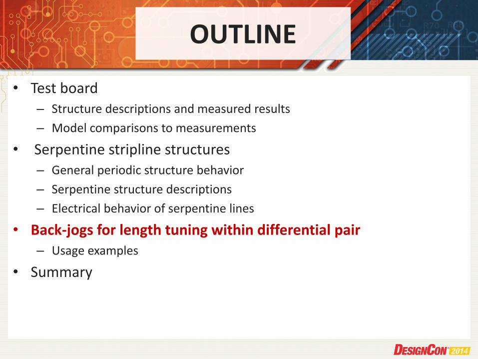
• Back-jogs for length tuning within differential pair – Usage examples
• Summary

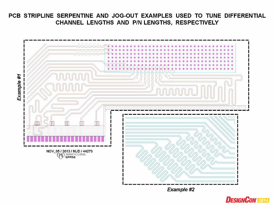
PCB BENDS
• Stripline bends in a PCB are required in several instances – Have to break-out of pin-fields to get to a routing channel
– From/To pins are not lined up so have to implement bends/turns
– Some nets require additional length to meet electrical timing requirements • These are meander or serpentine patterns – both have equivalent meaning
• For meander patterns, either minimize bends as much as possible with "trombone " patterns or add many more bends with "accordion" patterns – In practice, implementations may vary considerably depending on available
routing area, personal preference, etc.

PCB TEST STRUCTURES - DESCRIPTION
• We designed 12“ patterns with both trombone and accordion patterns and with both 90 degree and mitered bends (a 90 degree turn using two 45 degree turns) – Trombone pattern had just one down-and-back pattern
– Accordion pattern had 34 serpentine patterns, 136 bends + 1 more for entry into probe pads
– Patterns repeated 3 times to determine uniformity
• Board used low-loss Isola FR408 (Er=3.65, loss-tan=0.01) and tight 3313 weave (to minimize fiber-weave-skew)
• Striplines, all differential, were 5 mil wide with 10 mil space
• Dielectric thickness ~5 mils used to obtain ~100 ohm-differential impedance
• Used high bandwidth G-S-G-G-S-G microwave probes


PCB TEST STRUCTURES – MEASURED RESULTS
• Accordion patterns have noticeable sharp insertion loss drop-outs at 17.5 GHz – About 7 and 2.5 dB for 90 and 45 degree bends, respectively
• Measurements across three patterns are fairly consistent through ~18 GHz
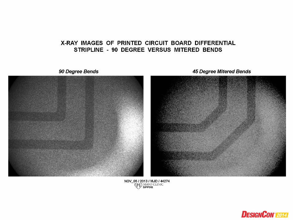
• We also took X-ray images of our bends – It is possible that PCB vendors augment design to remove sharp
corners (to avoid acid traps)
– Sharp corners (by design) may be etched away to some degree
– PCB software may not actually produce outer sharp corners, e.g., Gerber format produces corners with circular arcs
• Our 90 degree bends have under-etched inner corners and circulars arcs for outer corners


PCB TEST STRUCTURES – SIMULATION RESULTS
• We created 3-D full-wave EM model of accordion-style structures – Both for 90 and 45 degree bends
– Just model 1 of 34 structures and mathematically chain to realize model of complete structure
– Use manufacturer‘s laminate specifications for electrical parameters, we then adjust surface roughness to match our measured insertion losses
• Simulated insertion loss drop-outs are at correct frequency but lower magnitude than that measured – 4 vs. 7 dB and 1.5 vs. 2.5 dB
• Simulations do not show minor resonances – We believe ground stitching vias / planar cavities cause these


OUTLINE
• Test board – Structure descriptions and measured results
– Model comparisons to measurements
• Serpentine stripline structures – General periodic structure behavior
– Serpentine structure descriptions
– Electrical behavior of serpentine lines
• Back-jogs for length tuning within differential pair – Usage examples
• Summary

BEHAVIOR OF PERIODIC STRUCTURES
• We realize that our PCB bend structures are periodic – Actual repeating structure is one-half of serpentine structure, e.g.,
we have 68 repeating structures for 34 serpentines
• Simple circuit used to approximate our 34-structure with 90 degree bends – 68 lossy transmission lines with 15 fF capacitors between them to
match measured 9 dB drop-out at 17.5 GHz
• Periodic electrical behavior affected by several factors – Small down-and-back reflections get multiplied by N(=68)
patterns
– Sharp drop-outs occur at half wave-length multiples
– Reactances grow at higher frequencies which increase drop-out magnitudes
– Transmission line loss increases with frequency to decrease drop-out magnitudes


OUTLINE
• Test board – Structure descriptions and measured results
– Model comparisons to measurements
• Serpentine stripline structures – General periodic structure behavior
– Serpentine structure descriptions
– Electrical behavior of serpentine lines
• Back-jogs for length tuning within differential pair – Usage examples
• Summary

SERPENTINE STRUCTURE DESCRIPTIONS
• Serpentine examples – Periodic , up to 7 identical meander patterns (14 periodic structures)
• These can come from copying patterns or auto-generated by PCB software
– Note that longer meander patterns will cause resonances at lower frequencies
• Jog-out examples – In-line pin-field escape causes differential pair mismatch equal to pin-
field pitch (1 mm in this case)
– Typically require many jog-outs to equalize line lengths
– We‘ve assumed loosely-coupled striplines – additional problems if tightly coupled


OUTLINE
• Test board – Structure descriptions and measured results
– Model comparisons to measurements
• Serpentine stripline structures – General periodic structure behavior
– Serpentine structure descriptions
– Electrical behavior of serpentine lines
• Back-jogs for length tuning within differential pair – Usage examples
• Summary

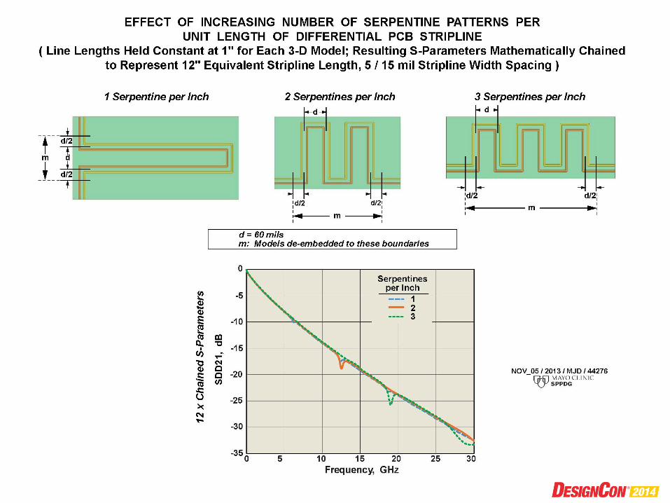
SERPENTINE STRUCTURE EXAMPLES
• Changing number of serpentines with fixed stripline length – We do see the half-wave (1st) resonance at the expected frequency
– The higher order resonaces are small or nonexistant • Possibly due to fact that repeating pattern has two discontiuities within repeating pattern
• Also capacitance is distributed rather than lumped
• Adjacent structure spacing – Here we do see resonance magnitude increase in higher order
harmonics
– Our model captures only 11 of 23 coupled regions (24 meander patterns in 12“ total length)
• Varying stripline width can greatly increase resonance magnitude – Larger discontinuity and lower stripline loss both act together
– Again, higher frequency resonances are missing


SERPENTINE STRUCTURE STUDY SUMMARY
• Typically, meandering lines should not have performance impacts – But there are some risk areas
• Lower risks by 1. Use mitered versus 90 degree bends
2. Use fewer longer (trombone) versus many shorter (accordion) serpentine patterns
3. Don‘t use repeating patterns – even small length adjustments could be beneficial
4. Don‘t crowd adjacent patterns too tightly
5. Be especially careful with wide lines (> 0.005“)
OUTLINE
• Test board – Structure descriptions and measured results
– Model comparisons to measurements
• Serpentine stripline structures – General periodic structure behavior
– Serpentine structure descriptions
– Electrical behavior of serpentine lines
• Back-jogs for length tuning within differential pair – Usage examples
• Summary

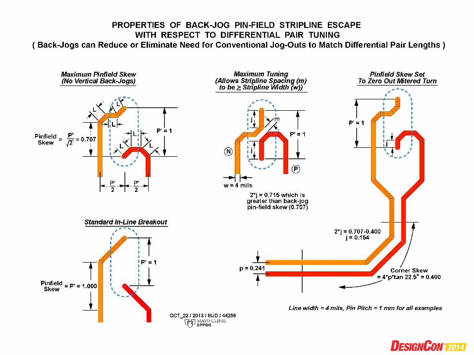
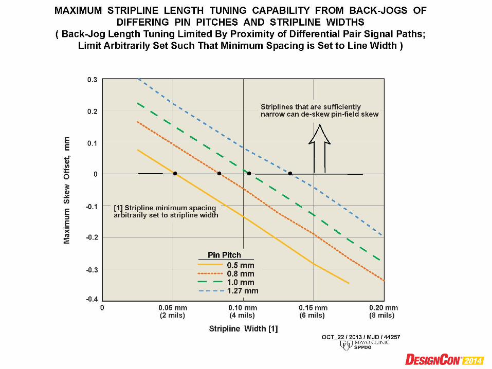
CORRECTING PIN-FIELD SKEW WITH BACK-JOGS
• We observe that a few stripline bends generally will not cause problems
• Use this result to try to reduce or eliminate jog-outs – Essentially route backward jog-outs, i.e., a back-jog to minimize pin-
field skew
• Standard break-outs are 45 degree paths toward outside of pin-field to reach routing channel between pin columns – Back-jog uses three bends with three equal length short segments to
reach between pin columns • This is our approach – other variations may be possible
• With shorter path backing up toward complement pin resulting baseline (maximum) skew is 0.707*pin-pitch
• Slide p/n striplines closer together to further reduce skew
• Minimum skew is dependant on pin-pitch and stripline width

BACK-JOG ELECTRICAL PERFORMANCE
• We simulated a standard versus back-jog pin-field escape – Assumes 100 mil thick PCB and 10 mil diameter vias having 13 mil via
stub, 26x65 mil oblong antipads
• Back-jog has somewhat higher return loss but lower frequency-dependant skew – Based on previous work, we believe that augmenting the antipad
shape can reduce back-jog return loss


OUTLINE
• Test board – Structure descriptions and measured results
– Model comparisons to measurements
• Serpentine stripline structures – General periodic structure behavior
– Serpentine structure descriptions
– Electrical behavior of serpentine lines
• Back-jogs for length tuning within differential pair – Usage examples
• Summary
BACK-JOG USAGE EXAMPLES
• It is difficult to manually lay out back-jogs in our PCB software
– Instead we automate using (Cadence) SKILL program
• Examples assume 1 mm pin pitch, 3/6 mil width/spacing
• Skew originates from pin-field break-out and bends
– Skew equations in paper
– Example shows that jog-outs can be reduced or eliminated versus standard (left-side) versus implementing back-jogs (right side)


SUMMARY
• Meandering lines not expected to be problematic for data-rates up to 10 Gb/s – Be more diligent for higher data-rates
• To reduce risk, use mitered bends and avoid high numbers of ‘perfectly’ repeated patterns
• Be careful when using wider striplines
• Don’t place adjacent serpentine patterns too closely
• Consider using back-jogs to eliminate or reduce jog-outs