practical camera auto-calibration based on object appearance and motion for traffic...
TRANSCRIPT

Practical Camera Auto-Calibration Based on Object Appearance and Motion forTraffic Scene Visual Surveillance
Zhaoxiang Zhang, Min Li, Kaiqi Huang and Tieniu TanNational Laboratory of Pattern Recognition,
Institute of Automation, Chinese Academy of Sciences{zxzhang, mli, kqhuang, tnt}@nlpr.ia.ac.cn
Abstract
Camera calibration, as a fundamental issue in computervision, is indispensable in many visual surveillance appli-cations. Firstly, calibrated camera can help to deal withperspective distortion of object appearance on image plane.Secondly, calibrated camera makes it possible to recovermetrics from images which are robust to scene or view an-gle changes. In addition, with calibrated cameras, we canmake use of prior information of 3D models to estimate 3Dpose of objects and make object detection or tracking morerobust to noise and occlusions.
In this paper, we propose an automatic method to recovercamera models from traffic scene surveillance videos. Withonly the camera height H measured, we can completely re-cover both intrinsic and extrinsic parameters of camerasbased on appearance and motion of objects in videos. Ex-periments are conducted in different scenes and experimen-tal results demonstrate the effectiveness and practicabilityof our approach, which can be adopted in many traffic scenesurveillance applications.
1. Introduction
Camera calibration, as a fundamental topic in com-puter vision, is not only essential for many computer vi-sion problems like stereo, metrology and reconstruction, butalso benefits many application tasks like intelligent visualsurveillance. Firstly, camera calibration can help to dealwith perspective distortion of object appearance on 2D im-age plane which is a very difficult problem to solve for most2D image feature based methods. Secondly, calibrated cam-eras make it possible to recover discriminant metrics robustto scene or view angle changes, which is greatly helpfulfor some applications like classification or tracking amongmulti-cameras. Thirdly, with cameras calibrated, we canmake use of prior information of 3D models to estimate real3D pose of objects in videos and make object detection or
tracking more robust to noise and occlusions.Due to its importance, much work has been done in the
field of camera calibration with all kinds of approaches pro-posed. The common practice for camera calibration is tocollect a set of correspondences between 3D points andtheir projections on image plane [4, 5]. However, a time-consuming wide site survey is required and it is difficult tomeasure 3D points which are not laid on the ground planein wide surveillance scenes. Alternative strategies are pro-posed by Tsai [9] with a 3D known metric structure andZhang [10] with a known planar template of unknown mo-tion. However, requirement of calibrated templates lim-its the practicability of surveillance algorithms to differentscenes. In addition, calibrated templates are not available inwide-field surveillance scenes because their projections areof very small size on image plane to supply poor accuracyfor calibration.
Auto-calibration methods seem to be a more suitableway to recover camera parameters for surveillance appli-cations. Since most surveillance applications make use ofonly one static camera, auto-calibartion cannot be achievedfrom camera motion but from inherent structure of monoc-ular scenes. Caprile and Torre [2] described methods touse vanishing points to recover intrinsic parameters from asingle camera but extrinsic parameters from multi-cameras.Liebowitz and etc. [6] developed a method to estimate in-trinsic parameters by Cholesky decomposition and appliedit to a scene reconstruction problem. Deutscher and etc.[3] made use of vanishing points in a Manhattan world torecover camera parameters for visual tracking. These meth-ods are based on extraction of vanishing points from staticscene structures such as buildings and landmarks.
In the absence of inherent scene structures, methods de-scribed above are not available. Researchers make use ofobject motion in videos to take the place of scene structure.Lv and etc. [8] obtained 3 orthogonal vanishing points byextracting head and feet positions of humans in videos onthe assumptions of constant human height and planar hu-man motion. As we know, precise pedestrian detection is
978-1-4244-2243-2/08/$25.00 ©2008 IEEE

very difficult in surveillance videos due to noise and shad-ows. Further more, the approach requires accurate localiza-tion of head and feet positions of humans, which is morechallenging in low resolution surveillance videos. Bose andetc. [1] tracked vehicles and detected constant velocity lin-ear paths to realize ground plane rectification instead of re-covering intrinsic and extrinsic camera parameters.
In this paper, we propose a novel automatic camera cali-bration method from traffic scene surveillance videos. Withmoving objects extracted from videos using motion infor-mation, three vanishing points corresponding to three or-thogonal directions in real 3D world are estimated basedon motion and appearance of moving objects. With onlythe camera height H measured, we can recover both in-trinsic and extrinsic camera parameters, which is of greathelp for all kinds of surveillance applications. Experimentsare conducted to evaluate the performance of this calibra-tion algorithm in different traffic scenes. Experimental re-sults demonstrate the accuracy and practicability of our ap-proach.
The remainder of the paper is organized as follows. InSection 2, we introduce our method to extract accurate fore-ground areas with shadows removed. The strategy to esti-mate 3 orthogonal vanishing points from motion and ap-pearance of video objects is described in Section 3. In Sec-tion 4, we introduce our method to realize calibration onlyfrom 3 orthogonal vanishing points and camera height H .Experimental results and analysis are given in Section 5.Finally, we draw our conclusions in Section 6.
2. Motion DetectionMotion and appearance of moving objects in surveil-
lance videos supply plentiful information for calibration. Inthis section, we introduce our method for extraction of accu-rate foreground areas with shadows removed. As we know,Gaussian Mixture Model (GMM) is a popular method inthe field of motion detection due to its outstanding ability todeal with slow lighting changes, periodical motions in clut-ter background, slow moving objects and long term scenechanges. However, this method still has disadvantages thatit cannot deal with fast illumination changes and shadowsvery well, which are very common in traffic scene surveil-lance. In our work, we adopt the method described in [11]to deal with disadvantages mentioned above and the methodcan be summarized as follows:(1) The intensity of each pixel is modeled as the product ofirradiance component and reflectance component.(2) The reflectance value of each pixel is modeled as a mix-ture of Gaussian.(3) Every new pixel is matched against each of the existingGaussian distributions. A match is defined as a pixel valuewithin 2.5 standard deviations of a distribution.(4) Sort the Gaussians and determine whether it is back-
ground.(5) Adjust the Gaussians and their prior weights.(6) If there is no match, replace the least probable Gaussianand set mask pixel to background.
Experimental results of background maintenance andmotion detection are shown in Figure 1. As we see, fore-ground objects are detected accurately with cast shadowsremoved.
(a) One frame of videos (b) Background recov-ered
(c) Detected movingobjects
Figure 1. Motion detection results with shadows removed (citedfrom [11])
3. Vanishing Points EstimationA vanishing point is defined as the intersection of a series
of projected parallel lines, which is very useful for auto-calibration. In this section, we propose our method to es-timate three orthogonal vanishing points from appearanceand motion of moving objects in videos.
In fact, conventional traffic surveillance scenes have aseries of helpful general properties for vanishing points es-timation which are summarized as follows:
• Almost all moving objects including vehicles andpedestrians are moving on the ground plane.
• Vehicles always run along the roadway which can beseen to be straight or contain one or more approxi-mately straight segments in the field of camera view.
• Image projection of vehicles are rich in line segmentsalong two orientations which correspond to the sym-metrical axis direction and its perpendicular directionin most view angles.
• In most cases, pedestrians are walking with their trunksperpendicular to the ground plane.
These four properties are found in most traffic surveil-lance scenes and they can be used to estimate three orthog-onal vanishing points, which are described in detail as fol-lows.
3.1. Coarse moving object classification
We extract two kinds of directions for every moving ob-jects detected from videos. The first one is the velocity di-rection in images, which can be calculated due to its posi-tion change of unit time. The second one is the main axis

direction θ, which can be estimated from moment analysisof silhouette as:
θ = arctan(2µ11
µ20 − µ02) (1)
Here, µpq is the central moment of order (p, q). The differ-ence between these two directions supplies coarse categoryinformation. As we know, the direction difference is quitesignificant for pedestrians moving in videos while the twodirections are very close for vehicles in most cases of cam-era view as shown in Figure 2. As a result, we take thedifference of these two directions as discriminant featurefor coarse classification. K-Mean clustering seems to be agood method for classification. However, due to large viewangle variance in the camera view field, we should adoptmore reliable strategy to avoid serious misclassification. Inpractice, we set two threshold values θ1 = 5◦ and θ2 = 20◦.The object is labeled as a vehicle if its direction differenceis less than θ1 and as a pedestrian if its direction differenceis larger than θ2. Those objects whose direction differenceis between θ1 and θ2 are discarded. The latter estimation ofvanishing points benefits from this strict classification strat-egy.
(a) Illustration of vehicles (b) Illustration of pedestrians
Figure 2. Illustrations in different view angles (Red arrowheadstands for velocity direction; blue arrowhead stands for main axisdirection)
It is evident that this classification is not very accuratebut enough for us to extract three orthogonal vanishingpoints as described in the following.
3.2. Line Equations Estimation
The four general properties in traffic surveillance sceneswe summarized before supply important information for re-covery of camera models.
Here, we assume that the roadway is straight in the fieldof view. Special cases of non-straight roadways will be dis-cussed in Section 5. In this case, most vehicles are run-ning in the same or inverse direction of the 3D world so thatthe symmetrical axes of most vehicles should be parallel toeach other, which are also parallel to the ground plane. Thissupplies important information for us to extract horizonalvanishing points. As we have described before, image pro-jection of vehicles are rich in line segments along two orien-tations which correspond to the symmetrical axis directionand its perpendicular direction. With these two orientationsextracted for each vehicle detected from videos, we can esti-mate their intersections corresponding to the two horizonalvanishing points, respectively.
Due to perspective distortion, projected orientation of 3Ddirection is not unique and related to its position in images.For accuracy, we try to extract two accurate line equationscorresponding to the two perpendicular directions for ev-ery vehicle detected from videos. Instead of sensitive edgepoint detection and combination to edge lines, these two ori-entations are extracted by Histogram of Orientated Gradient(HOG) in two stages. For every moving region labeled asvehicle detected from videos, the gradient magnitude andorientation are computed at every pixel within it. The ori-entation is divided into N bins and the histogram is formedby accumulating orientations within the region, weighted bythe gradient magnitude. Those two bins with the largest val-ues are chosen as coarse line orientations and a N bin HOGis calculated in each bin again to extract accurate line ori-entation, respectively. For every orientation estimated accu-rately, the line with this orientation slides from top to bot-tom of the region to determine its position in which the linemost fits image data by correlation. An example is illus-trated with line equations determined as shown in Figure 3.
HOG
HOG HOG
Figure 3. Flowchart for estimation of line equations for vehicles
For every vehicle, we can extract two line equations cor-responding to two 3D directions. Motion direction is ap-plied to distinguish these two directions. The line withits orientation close to motion direction corresponds to thesymmetric axis direction of the vehicle while the other onecorresponds to the perpendicular direction.
Pedestrians do not have so significant gradient orienta-tions. However, as we know, most pedestrians are walkingwith their trunk perpendicular to the ground plane in mostsituations. Instead of localizing head and feet position ina small region, we take the line with main axis orientationpassing by its centroid to describe trunk pose, which is morerobust to be used for estimation of vertical vanishing points.

3.3. Intersection Estimation
There are three kinds of lines estimated from detectedobjects in videos. The first kind corresponds to the symmet-ric axis direction in reality. The second kind corresponds toperpendicular direction of symmetric axis. The third kindcorresponds to the perpendicular direction of the groundplane.
With abundant objects detected from videos, we can col-lect large sets of lines for each kind and make use of themto estimate vanishing points. Due to large portion of out-liers and noise in videos, lines are in fact not intersected atthe same point. Various approaches can be adopted for ro-bust estimation of the intersection point from redundant lineequations. The simplest way is to solve simultaneous lineequations based on least square strategy. Also, the problemcan be transformed to estimate a point the sum of whose dis-tance to all lines is minimal. This is an optimization prob-lem which can be solved by Levenberg-Marquardt method.In addition, RANSAC is another strategy to solve this prob-lem which has been used in [8].
In spite of the accuracy and robustness supplied by theabove methods, they are not suitable to our case. In traf-fic scene surveillance, with videos processed and the framenumber increases, more and more moving objects are de-tected from videos and the set of extracted lines becomelarger and larger. The intersections should be estimatedfrom large sets of lines every moment without repeated cal-culation.
An improved voting strategy is adopted here for incre-mental estimation of intersections. It is based on the thoughtthat every point on the line is the possible candidate as theintersection. The possibility satisfies a Gaussian distribu-tion on the neighborhood due to the distance to the point.As a result, for every line l extracted from objects in videos,each point s(x, y) lying on l generates a Gaussian impulsein the voting space with (x, y) as its center. With time ac-cumulated, a voting surface can be generated and the posi-tion of its global extreme corresponds to the estimated in-tersection of lines. Compared to other estimation method,this strategy can estimate the positions of vanishing pointsevery moment without repeated calculation. Compared totraditional voting method, this strategy supplies more spic-ulate global extreme, smoother surface, and is more ro-bust to noise and outliers. One example of estimation ofthe vanishing point from voting surface is shown in Fig-ure 4. Line equations from vehicles are taken to estimate 2horizonal vanishing points while those from pedestrians aretaken to estimate 1 vertical vanishing points. In this way, wecan extract 3 orthogonal vanishing points (u1, v1), (u2, v2),(u3, v3) from appearance and motion information of mov-ing objects in traffic scene surveillance videos.
(a) Illustration of a traffic scene (b) Voting surface
Figure 4. Illustration of estimating vanishing points from trafficscenes
4. Camera CalibrationIn this section, we introduce our approach to recover
camera models from vanishing points.For a pin-hole camera, perspective projection from the
3D world to an image can be conveniently represented inhomogeneous coordinates by the projection matrix P:
λi
ui
vi
1
= P
Xi
Yi
Zi
1
= K [R T]
Xi
Yi
Zi
1
(2)
As we know, the P can be further decomposed into the 3×3rotation matrix R, the 3 × 1 translation vector T and theintrinsic parameter matrix K which has the form as
K =
αu s u0
0 αv v0
0 0 1
(3)
With the assumption of zero skew (s = 0) and unit aspectratio (αu = αv = f) for surveillance cameras, the K issimplified to have only 3 degrees of freedom.
4.1. Recovery of K and R
The 3 vanishing points correspond to the 3 orthogonaldirections in the 3D space, which are chosen to set up theworld coordinate system. Due to the fact that points in infin-ity correspond to the 3 orthogonal directions, we can derivethe constraints as: λ1u1 λ2u2 λ3u3
λ1v1 λ2v2 λ3v3
λ1 λ2 λ3
= P
1 0 00 1 00 0 10 0 0
= KR (4)
Since the rotation matrix R satisfies R · RT = I, (4) canbe rearranged to derive constraints on K as: u1 u2 u3
v1 v2 v3
1 1 1
λ21 0 00 λ2
2 00 0 λ2
3
u1 u2 u3
v1 v2 v3
1 1 1
T
= KKT (5)
Under the assumption of unit aspect ratio and zero skew,(5) can be solved to recover 3 intrinsic camera parametersand the 3 unknown factors, λ2
i . A more robust strategy is toassume the main point (u0, v0) lying on the middle of imageplane so that we only need to solve f from (5).
With K and λi solved, they can be substituted into (4) tosolve the rotation matrix R.
4.2. Recovery of T
Traditionally, the translation matrix T is recovered fromcorrespondence between two or more views. However, onlyone static camera is usually used in surveillance applica-tions. In this case, we can choose one arbitrary referencepoint (u4, v4) from image plane to correspond to the originof the world coordinate system so that:
λ4
u4
v4
1
= K [R T]
0001
= KT (6)
This supplies two constraints about T, which leaves thescale factor λ4 and is not sufficient to completely solve T.
As we know, surveillance cameras are always mountedquite high from the ground plane so that the Z coordinate ofthe optical center can be simply estimated as the distance Hbetween the camera and the ground plane. We will derivetwo other constraints from this metric.
The first property we can use is that the image projectedpoint (u, v) of every point in z = H plane are on theline across the two horizonal vanishing points (u1, v1) and(u2, v2). This lead to a linear equation about T as:
(u − u1)(v1 − v2) − (v − v1)(u1 − u2) = 0 (7)
The other property is that the optical center of the cameralies on the z = H plane so that
−R−1T =
xc
yc
H
(8)
where (xc, yc) is the coordinate of optical center on theworld coordinate system. So another linear equation aboutT can be derived from (8). The above derived simultaneousequations are sufficient to recover the translation matrix T.
In this section, we propose our method of complete cali-bration of surveillance scenes with three estimated orthogo-nal vanishing points and the measured camera height H . Inthe next section, experiments are conducted to evaluate theperformance of our auto-calibration method.
5. Experimental Results and AnalysisExperiments are conducted in different scenes and exper-
imental results are presented in this section to demonstratethe performance of the proposed approach.
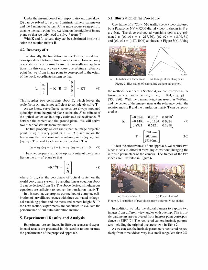
5.1. Illustration of the Procedure
One frame of a 720 × 576 traffic scene video capturedby a Panasonic NV-MX500 digital video is shown in Fig-ure 5(a). The three orthogonal vanishing points are esti-mated as (u1, v1) = (−217, 70), (u2, v2) = (1806, 31)and (u3, v3) = (427, 4906) as shown in Figure 5(b). Using
(a) Illustration of a traffic scene
(u1, v1)
(u2, v2) (u3, v3)
(b) Triangle of vanishing points
Figure 5. Illustration of estimating camera parameters
the methods described in Section 4, we can recover the in-trinsic camera parameters: αu = αv = 884, (u0, v0) =(336, 226). With the camera height measured as 7420mmand the center of the image taken as the reference point, therotation matrix R and the translation matrix T can be recov-ered as:
R =
−0.5244 0.8512 0.0190−0.1484 −0.1134 0.98240.8384 0.5124 0.1858
(9)
T =
781mm2020mm29180mm
(10)
To test the effectiveness of our approach, we capture twoother videos in different view angles without changing theintrinsic parameters of the camera. The frames of the twovideos are illustrated in Figure 6.
(a) Frame of video1 (b) Frame of video2
Figure 6. Illustration of two videos from different view angles
In addition, we take the digital camera to capture twoimages from different view angles with overlap. The intrin-sic parameters are recovered from interest point correspon-dence by SIFT [7]. The recovered camera intrinsic parame-ters including the original one are shown in Table 2.
As we can see, the intrinsic parameters recovered respec-tively from three videos vary in a small range less than 2%.

Table 1. Recovered intrinsic parameters of the digital camera
parameter f u0 v0
original video 884 336 226video1 872 325 234video2 893 342 238SIFT 880 332 231
Further more, it is comparable to the method based on in-terest point correspondence. It is shown that our calibrationmethod is accurate to be adaptive to different view angles.Many vanishing points based auto-calibration methods arenot applicable because they cannot estimate the position ofvanishing points accurately. In our approach, we make useof motion and appearance information of moving objects,which is very redundant for recovery of vanishing points. Inaddition, voting strategy is applied to get rid of outliers. Inthis case, our approach can estimate vanishing points quiteaccurately so that we can recover accurate camera parame-ters.
5.2. Comparison to Point Set CorrespondenceBased Method
For traffic scene surveillance, the most conventionalmethod for camera calibration is based on point correspon-dence between 3D real scenes and 2D images [4]. In or-der to estimate accurate projection matrix, we need to sur-vey the whole scene and label points distributed averagelywithin the whole scene. To compare with our approach, wemanually labeled more than 60 points and mark the corre-sponding point in the image plane as shown in Figure 7. 20
Figure 7. Correspondence of labeled points on image plane
points of them are selected and Direct linear transformation(DLT) method is applied to recover the projection matrix P
based on the least square strategy as:
P =
−195.67 912.46 83.77 942915850.74 17.79 897.79 92706930.68 0.70 0.15 32739
(11)
In comparison, the projection matrix recovered by our ap-proach is:
P =
−181.94 925.3 79.3 1050494658.87 15.8835 911.18 84039570.84 0.51 0.19 29180
(12)
Experiments are conducted to compare the projectionmatrix calculated by DLT and our method using the other 40corresponding pairs. We find that our approach gives morethan 3% higher accuracy. The possible reason is that label-ing of points in surveillance scenes are focus on the groundplane. It is difficult to collect abundant points which arenot lied on the ground plane. In addition, manually labeledpoints cannot cover the whole scene averagely. In contrast,our approach makes use of motion and appearance infor-mation of moving objects, which supplies very redundantdirection information to achieve accurate calibration.
5.3. Testing with Real Scene Measurement from Im-ages
The performance of camera calibration can be evaluatedby measurement of real length ratio from images. As shownin Figure 8, we take one length as unit length and 27 lengthratio are measured from images. The measured value andthe ground truth of every value are listed in Table 2.
1l2l3l4l
5l
6l
7l8l9l10l
11l
12l
13l
14l
15l
16l
17l 18l
19l 20
l 21l
22l 23
l
25l
24l
27l
26l
1
Figure 8. Scene measurement from images
As we can see, the average error of measurement isless than 10% which demonstrate the effectiveness of ourapproach. Two phenomena from the experimental resultsshow some disadvantages of our approach. The first oneis that those lines near the camera are measured more ac-curately than those far away. This is related to the mea-sured pixel error on the image plane. The second one

Table 2. Measurement from images of the digital camera
Label l1 l2 l3 l4 l5 l6 l7Test 0.94 1.01 1.03 1.05 0.96 1.02 0.40Real 1.00 1.00 1.00 1.00 1.00 1.00 0.46Label l8 l9 l10 l11 l12 l13 l14Test 0.40 0.48 0.46 0.52 0.48 0.50 1.94Real 0.46 0.46 0.46 0.46 0.46 0.46 2.11Label l15 l16 l17 l18 l19 l20 l21Test 1.92 2.04 0.91 0.99 2.23 2.25 2.07Real 2.11 2.11 1.13 1.13 2.11 2.11 2.11Label l22 l23 l24 l25 l26 l27 l28Test 1.10 1.12 0.49 1.39 0.51 0.48 1.42Real 1.13 1.13 0.52 1.50 0.52 0.52 1.50
is that those lines which are parallel to the ground planeare measured more accurately than those perpendicular tothe ground plane. That is because the horizonal vanishingpoints estimated from vehicles are more accurate than thevertical one from pedestrians. More accurate estimation ofvertical vanishing points can boost performance of our ap-proach.
5.4. Degenerate Cases
Some degenerate cases may lead to invalidation of ourapproach. As we know, if the camera plane is parallel orperpendicular to the ground plane, we cannot recover thewhole 3 orthogonal vanishing points from videos. In thesecases, we should have more information like more verticalor horizonal lines to realize complete camera calibration.Fortunately, surveillance applications always like to mountthe camera with a titled angle to the ground plane to covera wider view field. As a result, these extreme cases are notcommon at all in surveillance applications.
5.5. Discussion
In the above, we assume that the roadway is straightin the field of view, which is not always true in real ap-plications. Even though the roadway is not straight, theremust be one or more approximately straight segments in thefield of view. The longest straight segment will generatethe global conspicuous peak in voting space to estimate thetwo orthogonal horizonal vanishing points. As a result, ourapproach still works in this case.
Another special case is that there are more than one road-way in the field of view. For example, the surveillance scenecontains a crossroad as shown in Figure 9. This will lead totwo evident peaks in the voting surface for horizonal van-ishing points estimation. In most cases, the two roads havenot the same traffic flow in a period of time. As a result, thetwo peaks are of different height so that they can be distin-
guished from each other. Two groups of three orthogonalvanishing points can be estimated and the camera param-eters can be recovered from these two groups with a leastsquare strategy.
Figure 9. Illustration of scene containing crossroad
In our framework, we design a very simple strategy forobject classification in videos. Two thresholds are adoptedand a part of samples are discarded. There are two reasonsfor us to use this strategy. The first is that voting basedestimation need not very accurate classification. The secondis that our calibration result is useful for classification sothat it can even be feed back to the classification step tooutput more accurate result.
In addition, due to the unknown intrinsic structure ofcameras, the camera optical center height H cannot be mea-sured accurately. In our work, we use the distance betweencamera and the ground plane to approximate this value. Aswe know, cameras are mounted very high in surveillanceapplications so that the measure error of H is less than 2%.Even more, the error of H only effect the translation matrixT. It can be validated that the estimation error of T is lessthan 2% in existing of 2% measure error of H .
5.6. Applications
Accurate automatic calibration from videos has great po-tential to be applied to all kinds of traffic scene surveil-lance applications. In recent years, appearance based objectrecognition is more popular than 3D model based method.The reason is that the 3D model based method needs priorcamera calibration step which limits its applications. Withour approach applied, the 3D model based method can beautomatically applied to all kinds of traffic surveillancescenes without manual calibration. Also, classification ofobjects in surveillance video is difficult due to the perspec-tive distortion of objects. The most common phenomenonis that close objects seems to be larger and move faster thanthose far away. With our approach applied to object classi-fication, 2D motion and shape features like speed and size

can be normalized to be invariant to view angle changes. Inthis case, motion and shape features can greatly contributeto the classification accuracy.
6. Conclusions
In this paper, we have proposed a practical camera auto-calibration method for traffic scene surveillance. With onlythe camera height H measured, we can completely recoverboth intrinsic and extrinsic parameters of cameras based onappearance and motion of moving objects in videos. Ex-perimental results have demonstrated accuracy and practi-cability of our approach, which can be used in all kinds ofsurveillance applications like model based object recogni-tion, coarse object classification and metric measurementfrom images.
Acknowledgement
This work is funded by research grants from the Na-tional Basic Research Program of China (2004CB318110),the National Science Foundation (60605014, 60332010,60335010 and 2004DFA06900), and the CASIA Innova-tion Fund for Young Scientists. The authors also thank theanonymous reviewers for their valuable comments.
References[1] B. Bose and E. Grimson. Ground plane rectification by track-
ing moving objects. In Proceedings of the Joint InternationalWorkshops on Visual Surveillance and Performance Evalua-tion of Tracking and Surveillance, 2003.
[2] B. Caprile and V. Grimson. Using vanishing points for cam-era calibration. International Journal of Computer Vision,4:127–140, 1990.
[3] J. Deutscher, M. Isard, and J. MacCormick. Automatic cam-era calibration from a single manhttan image. In Proceedingsof European Conference on Computer Vision, 2002.
[4] O. Faugeras. Three dimensional computer vision: A geomet-ric viewpoint. MIT Press, 1993.
[5] R. I. Hartley and A. Zisserman. Multiple View Geometryin Computer Vision. Cambridge University Press, ISBN:0521540518, second edition, 2004.
[6] D. Liebowitz, A. Criminisi, and A. Zisserman. Creatingarchitecural models from images. In Proceedings of Euro-Graphics, 1999.
[7] D. Lowe. Distinctive image features from scale-invariantkeypoints. International Journal of Computer Vision,60(2):91–110, 2004.
[8] F. Lv, T. Zhao, and R. Nevatia. Camera calibration fromvideo of a walking human. IEEE Transactions on PatternAnalysis and Machine Intelligence, 28(9), 2006.
[9] R. Tsai. An efficient and accurate camera calibration tech-nique for 3d machine vision. In Proceedings of IEEE Con-ference on Computer Vision and Pattern Recognition, 1986.
[10] Z. Zhang. A flexible new technique for camera calibration.In Proceedings of 7th International Conference on ComputerVision, 1999.
[11] Z. X. Zhang, Y. Cai, K. Huang, and T. Tan. Real-time mov-ing object classification with automatic scene division. InIn Proc. of International Conference on Image Processing,2007.