ppr: partial packet recovery for wireless networks · the ppr system allows the link/mac layer to...
TRANSCRIPT

Computer Science and Artificial Intelligence Laboratory
Technical Report
m a s s a c h u s e t t s i n s t i t u t e o f t e c h n o l o g y, c a m b r i d g e , m a 0 213 9 u s a — w w w. c s a i l . m i t . e d u
MIT-CSAIL-TR-2007-008 February 2, 2007
PPR: Partial Packet Recovery for Wireless NetworksKyle Jamieson and Hari Balakrishnan

PPR: Partial Packet Recovery forWireless Networks
Kyle Jamieson and Hari BalakrishnanMIT Computer Science and Artificial Intelligence Lab
{jamieson, hari}@csail.mit.edu
Abstract
Bit errors occur over wireless channels when the signal isn’t strong enough toovercome the effects of interference and noise. Current wireless protocols may useforward error correction (FEC) to correct for some (small) number of bit errors,but generally retransmit the whole packet if the FEC is insufficient. We observethat current wireless mesh network protocols retransmit a number of packets andthat most of these retransmissions end up sending bits that have already been re-ceived multiple times, wasting network capacity. To overcome this inefficiency, wedevelop, implement, and evaluate a partial packet recovery (PPR) system.
PPR incorporates three new ideas: (1) SoftPHY, an expanded physical layer(PHY) interface to provide hints to the higher layers about how “close” the actualreceived symbol was to the one decoded, (2) a postamble scheme to recover dataeven when a packet’s preamble is corrupted and not decodable at the receiver,and (3) PP-ARQ, an asynchronous link-layer retransmission protocol that allows areceiver to compactly encode and request for retransmission only those portions ofa packet that are likely in error.
Our experimental results from a 27-node 802.15.4 testbed that includes Te-los motes with 2.4 GHz Chipcon radios and GNU Radio nodes implementing theZigbee standard (802.15.4) show that PPR increases the frame delivery rate by afactor of 2× under moderate load, and 7× under heavy load when many links havemarginal quality.
1 IntroductionBit errors over wireless channels occur when the signal to interference and noise ratio(SINR) is not high enough to decode information correctly. Poor SINR is usually the re-sult of noise caused by sources external to the network, and interference caused by oneor more other concurrent transmissions in the network, and varies in time even withina single packet transmission. Even with a variety of physical layer (PHY) techniquessuch as soft-decision decoding [10], spread spectrum modulation, channel coding, andthe like, current systems rely heavily on link-layer retransmissions to recover from bit
This work was supported by the National Science Foundation under Award Numbers CNS-0520032 andCNS-0205445.
1

errors and achieve high throughput. Because wireless channels are hard to model andpredict, designing an error-free communication link generally entails sacrificing signif-icant capacity; instead, a design that occasionally causes errors to occur fares better inthis regard. Link-layer retransmissions allow a receiver to recover from lost packets.
Retransmitting entire packets works well over wired networks where bit-level cor-ruption is rare and a packet loss implies that all the bits of the packet were lost (e.g.,due to a queue overflow). Over radio, however, all the bits in a packet don’t share thesame fate: wery often, only a small number of bits in a packet are in error and othersare correct. Thus, it is wasteful to re-send the entire packet when only a small part ofit is lost. Our goal is to eliminate this waste, ideally by never re-sending those portionsof the packet that have already been received correctly.
There are several challenges in realizing this goal. First, how can a receiver tellwhich bits are correct and which are not? Second, since most PHY schemes requirethe receiver to synchronize with the sender on a preamble before decoding a packet’scontents, wouldn’t any corruption to the preamble (caused, for instance, by a packetcollision from another transmission) greatly diminish the potential benefits of the pro-posed scheme? Third, how can higher layer protocols use partial packets to improveend-to-end performance?
This paper presents the design, implementation, and evaluation of PPR, a PartialPacket Recovery system that improves aggregate network capacity by greatly reducingthe number of redundant bit transmissions. It incorporates three new techniques to meetthe challenges mentioned above:
1. SoftPHY allows a receiver to determine, with no additional feedback or informa-tion from the sender, which groups of bits (symbols) are likely to be correct inany given packet reception using hints from the PHY. The key insight in Soft-PHY is that the PHY maintains information about how close the received symbolwas to what it decoded and reported to the higher layer. The higher layer can usethis information, propagated from the PHY, as a hint. Section 3 develops thisidea further.
2. Postamble decoding allows a receiver to receive and decode bits correctly evenfrom packets whose preambles are corrupted. The main idea here is to replicatethe preamble and packet headers in a postamble and a packet trailer, allowing areceiver to lock on the postamble and then “roll back” in time to recover datathat was previously impossible to obtain. Section 4 describes the details of thisscheme.
3. PP-ARQ, a link-layer retransmission protocol in which the receiver compactlyrequests and encodes the retransmission of only select portions of a packet. Thiscompact encoding is done using a dynamic programming algorithm that mini-mizes the expected bit overhead of communicating this feedback, balancing thatagainst the cost of the sender retransmitting bits already received correctly. Sec-tion 5 describes PP-ARQ.
We have implemented all three components on the GNU Radio platform for802.15.4, the Zigbee standard. Our implementation is compatible with that specifica-tion (see Section 6). The SoftPHY and postamble decoding steps running at the receivercan recover partial packets from unmodified Zigbee senders, while PP-ARQ requiresmodifications to the sender as well.
2

Preamble frame synchronization
Bits + SoftPHY hints
PP-ARQPackets
Postamble frame synchronization
Viterbi decoderMatched filter
Soft-decision decoderHard-decision decoder
Partial packets + SoftPHY hints
SoftPHY
Interface
Figure 1: Block diagram of the PPR system; dark blocks and the SoftPHY interface arethe contributions of this paper. PPR sits above one of many different types of receiverstructure, as discussed in Section 3. The SoftPHY interface passes up hints from thereceiver to PP-ARQ, the partial packet retransmission layer, described in Section 5.Postamble decoding, described in Section 4, increases the number of opportunities forrecovering partial packets from the receiver.
We have conducted several experiments over a 25-node indoor testbed consistingof Telos motes with 2.4 GHz Zigbee radios from Chipcon and four GNU Radio nodes.These results, described in Section 7, show factor-of-two gains in the packet deliveryrate and per-link throughput with PPR over the status quo under moderate load. Wealso compare PPR to other ways of determining which bits in a packet are likely to becorrect, such as fragmented CRCs on packets. There we find that on the links with thelowest loss rates (which would be the ones selected by routing protocols), the raw suc-cess rate improves by 1.6×. These gains are even higher (7× better per-link throughput)under heavy load, which causes a number of links to have marginal quality.
2 Design OverviewThe PPR system allows the link/MAC layer to estimate which bits of any given re-ception are likely to be correct and use that information to improve packet deliveryrates and throughput. To understand how its three components (SoftPHY, postambledecoding, and PP-ARQ) work and interface with each other, a conceptual model of thewireless communication system will be helpful. This model is intentionally simple anddoesn’t capture the breadth of designs where PPR can be useful, but describes a typi-cal instance of a direct-sequence spread spectrum (DSSS) radio. This model applies toboth 802.15.4 (Zigbee) and 802.11b/g (WiFi), two common standards.
At the sender, the network layer passes packets to the link/MAC layer, which placesa header that includes the link-layer source address, link-layer destination address, anda CRC covering the entire link-layer packet’s contents at the end of the packet.1 Thelink layer then passes a stream of bits to the PHY.
There are many ways to implement a DSSS sender. In one approach, the PHY mapsgroups of b bits to a B-bit codeword. In Zigbee, for instance, b = 4 and B = 32. Sincethere are only 2b b-bit strings, the space of valid codewords is extremely sparse. Eachcodeword (actually, the sequence of codewords) is broken up into groups of k ≥ 1, each
1Later, we will investigate the performance of fragment-CRC schemes that place multiple CRCs in thepacket.
3

group mapping to a channel symbol or chip, and sent over the air modulated over somewaveform (in Zigbee, k = 1). Thus, each bit in the original packet gets spread overmany chips.
At the receiver, in current systems, the PHY produces a sequence of bits after de-modulating incoming waveforms and decoding symbols. This interface is rather limit-ing in that the link/MAC layer has no easy way of telling which bits are almost certainlycorrect, and which bits are more questionable. The PHY, however, has this information;for example, when decoding received waveform samples to a codeword, it knows howclose the actual reception was to the closest valid codeword, and can propagate thatinformation up as a confidence. If it uses a maximum-likelihood estimator in demod-ulation, then it can propagate the likelihood as a confidence too. We use this insightin developing PPR’s SoftPHY interface, shown in Figure 1 and described in detail inSection 3.
In the status quo, no processing of a packet payload can occur without the success-ful receipt of a preamble. Unfortunately, when collisions occur, the preamble is oftendestroyed. Our postamble decoding scheme, shown in Figure 1 and described in Sec-tion 4, overcomes this problem by allowing a receiver to recover data even when thepreamble is lost. We also replicate the information in the header in a trailer at the endof the packet. Figure 2 shows the layout of the information in a typical PPR packet.
Finally, once SoftPHY propagates confidence information together with each groupof bits to the link/MAC layer, there are several ways to use it. We develop PP-ARQ,a retransmission protocol where the receiver sends a request to the sender to re-sendonly those bit ranges where there are several bits likely wrong. In response, the senderretransmits the bits from those ranges and sends CRC values for the other ranges, sothat the receiver can be certain that the bits in the non-retransmitted portions are cor-rect. Other ways to use SoftPHY information include integrating it with forwardingprotocols or opportunistic routing protocols, forwarding only the bits likely to be cor-rect. We do not investigate that possibility in this paper, focusing instead on improvingARQ (see Section 5).
The underlying premise in PPR is that significant performance gains can be ob-tained by being a little more flexible about the granularity of error recovery in wirelessnetworks. A finer granularity than packets can help improve performance in both accesspoint-based networks and wireless mesh networks. Section 7 shows several experimen-tal results that confirm this premise.
3 SoftPHYIn the abstract, the SoftPHY interface is simple: annotate each group of bits propagatedto the higher layer with a confidence metric. The details of how the confidence metricis calculated and what it actually means, however, depend on how the PHY works. Webelieve, however, that most demodulation and decoding methods maintain this infor-mation. For three common designs, we outline what this information would be, thendiscuss the method we implemented, and finally discuss how higher layers should bedesigned to interpret these hints, given that what the information means depends onwhat the PHY does.
4

b bits
S/B codewords
B symbols
Packet preamble Packet postambleCodewordSymbol
lendstsrc
lendstsrc
Header Trailer
Figure 2: A packet is composed of symbols, which may be organized into codewords ofB symbols each by channel coding or direct-sequence spread spectrum. Each codewordencodes b data bits.
3.1 Options for PHY HintsAt a high level, the PHY generally includes a demodulator and a channel decoder. Wepropose three ways of obtaining PHY hints that apply to three popular designs.
Hamming distance in hard-decision decoding. In one common PHY design, thedemodulator makes a hard decision [10, Chp. 8] of what symbol any given samplewaveform corresponds to (and therefore what group of k ≥ 1 bits they correspond to),independent of other receptions. It then sends that information to the channel decoder,which maps the received word to the closest (most likely) codeword. The closenessof this mapping, measured as the Hamming distance between the received work andthe codeword (the number of distinct elements between the two words), can serve as auseful confidence hint: a low distance inspires confidence in the correctness of the bits,while a large one does not.
Correlation metric in soft-decision decoding. To cope better with Gaussian noise,a more efficient option than hard decoding is to use soft-decision decoding (SDD) [10,Chp. 8].2 Here, the demodulator passes samples of received symbols. The decoder thenmakes codeword decisions on groups of received symbols using a correlation metricthat takes into account these samples. However, SDD will still produce incorrect code-words if the SINR is low, and does not recover correct bits in the presence of packetcollisions particularly well.
With SDD, the receiver calculates a correlation metric C between the received sam-ples R and each codeword Ci (whose jth bit is ci j) defined as [10, Ch. 8]:
C (R,Ci) =n∑
j=1
(2ci j − 1
)ri j (1)
This metric can serve as a useful hint from the PHY to higher layers: a larger metricinspires confidence that the bits are correct.
We also note that a particularly interesting instance of a confidence metric whenconvolutional decoding is used with soft-decision decoding is to use the output of theViterbi decoder [11]. This output is the likelihood of is a measure of how well the
2SDD improves BER by 2 to 3 dB over HDD in the presence of noise.
5
received sequence of codewords matched with the path through the coding trellis asso-ciated with the decided-upon codeword.
Matched filter demodulator output. PHY hints can also be obtained from thedemodulator itself in the absence of any channel coding. The receiver structure foroptimal detection of signals over an additive white Gaussian noise (AWGN) channelis a filter matched to the shape of the incoming signal [10, Ch. 5]. The output of thismatched filter is the correlation function between the received signal and the decided-upon codeword. The SoftPHY hint is then simply the output of the matched filter; alarger value signifies higher confidence.
3.2 Hamming Distance as a HintWe conducted preliminary experiments with the HDD and SDD schemes describedabove. We found that our bit errors were mostly due to collisions, and in this case, thedifference between HDD and SDD was not significant. Because the HDD implemen-tation was conceptually simpler, we developed a complete implementation of that ideaand conducted several experiments with it (described in detail in Section 7). Here, wegive a brief summary of one experimental result that shows that the Hamming distanceis a good SoftPHY hint.
This experiment was done over a 27-node testbed of 802.15.4 Chipcon and GNURadios described in Section 7. 23 of the nodes send packets whose payload is a knowntest pattern at a constant rate. There are four receivers (each receiver is able to hear anddecode some subset of the 23 senders). Figure 3 shows the distribution of Hammingdistance across each received codeword, demarcated by whether the codeword wascorrectly or incorrectly received (we know this from the test pattern). Conditioned on acorrect decoding, 96% of codewords have a Hamming distance of 1 or less. In contrast,barely 10% of the incorrect codewords have a distance of 6 or less.
This result shows that the higher layer must actually interpret this SoftPHY hintwith a threshold rule. We denote the threshold by η, so that the higher layer labelsgroups of bits with d ≤ η “good” and groups of bits with d > η “bad”. This graph,and later results in Section 7.4, show that a large Hamming distance is an excellentindication of symbol incorrectness, while a small Hamming distance is a good predictorof codeword correctness.
3.3 Architectural Implications of SoftPHY HintsAlthough the SoftPHY interface can be provided for a variety of PHY implementa-tions, the semantics of the delivered information is intimately tied to the details of thePHY. One of the benefits of protocol layering is that higher layers are shielded fromthe details of the lower ones, and SoftPHY has the potential danger of violating thisabstraction barrier in the interest of performance. Here, we argue that it is possible toimplement higher layers without violating the abstraction boundary.
To do that, the higher layers must not be aware of exactly how the information iscalculated. Instead, they should adapt their threshold or other decisions to label groupsof bits as “good” or “bad” to actual observation. For example, the link/MAC layer couldobserve the correlation between a particular threshold and the correctness of the hint,
6

0
0.2
0.4
0.6
0.8
1
0 3 6 9 12
Cu
mu
lati
ve
dis
trib
uti
on
Hamming distance
3.5 Kbits/s/node, correct codewords
3.5 Kbits/s/node, incorrect codewords
6.9 Kbits/s/node, correct codewords
6.9 Kbits/s/node, incorrect codewords
13.8 Kbits/s/node, correct codewords
13.8 Kbits/s/node, incorrect codewords
Figure 3: The distribution of hamming distances for every codeword in every receivedpacket, separated by whether the received codeword was correctly or incorrectly de-coded. For correctly-decoded codewords, hamming distance is low; for incorrectly-decoded codewords, hamming distance is high.
and adapt the threshold dynamically. This approach can be used as long as the PHYsimply provides a “monotonicity” contract; i.e., given any two hint values, h1 and h2,h1 < h2 always implies that the PHY has a higher confidence in the bits associated withh1 than with h2 (or vice versa). Implementing such a contract is straightforward for thePHY, at least for the three options we laid out above.
In some ways, SoftPHY might seem analogous to soft-decision decoding, but thereis a crucial architectural difference. With soft-decision decoding, the demodulator’sinterface to the decoder is quite different from hard decoding. In the former, the de-modulator doesn’t even attempt to make a decoding decision, instead propagating allreceived signal samples up to the decoder. In contrast, with our SoftPHY design, thePHY doesn’t simply pass up all its raw information to the higher layer, so layeringboundaries are preserved and the PHY still makes “hard” decisions. However, the PHYdoes pass hints upwards about its confidence in each decision it makes. This architec-ture preserves a clean decomposition between PHY and higher layers, while enablingperformance gains.
3.4 An Alternative to SoftPHY: Per-Fragment CRCWe will show later that SoftPHY improves performance significantly, but one mightask whether it is necessary to achieve similar gains. One cannot ignore the benefits ofthe boundaries between the PHY and higher layers in the status quo, so it is importantthat we investigate how necessary SoftPHY hints are, in addition to how much theyimprove performance. One way to approximate SoftPHY is to send multiple CRCsper packet, one per fragment of the packet, as shown in Figure 4. This scheme allows
7

Fragment
Fragmentchecksum
Figure 4: Multiple CRC checksums sent per packet, with each CRC taken over a dif-ferent fragment of the packet.
(P1)
(P2)
(P3)
(P4)
Figure 5: A collision between many packets. We use the postamble to partially decodepackets P3 and P4, and the techniques described in Sections 3 and 5 to detect theincorrect parts of each packet and request retransmission of just those parts.
the receiver to identify entire fragments that are correct. If bit errors are concentratedin only a few bursts, then entire fragments will check out correctly, and the receiverwould then only have to recover the erroneous fragments from the sender.
How big must a fragment, c, be? In an implementation, one might place a CRCevery c bits, where c varies in time. If the current value leads to a large number ofcontiguous error-free fragments, then c should be increased; otherwise, it should bereduced (or remain the same). Alternatively, one might observe the symbol error rate(or bit error rate), assume some model for how these errors occur, and derive an analyt-ically optimal fragment size (which will change with time as the error rate changes).
In Section 7, we investigate the “best case” for CRC fragments, finding post factofrom traces of errored and error-free symbols what the optimal fragment size is andusing that value.
4 Decoding Packets Without a PreambleWhen errors occur in the preamble due to collisions or noise, the receiver will not beable to synchronize to the incoming transmission and decode any bits. In that case, thebenefits of SoftPHY will go unrealized. We need a way to cope with preamble loss, forexample, in the multi-packet collision in Figure 5. In this example, packet P4 wouldnot be received at all, because its preamble would not have been decoded correctly,while packet P3 would be received only partially.
8

Our approach to synchronizing on packets without an intelligible preamble is sim-ple: add a postamble to the end of each packet on which a receiver can also synchro-nize. Like the preamble, the postamble has a well-known sequence attached to it thatuniquely identifies it as the postamble, and differentiates it from a preamble. In addi-tion, we add a trailer near the postamble at the end of the packet, as shown in Figure 2.The trailer contains the packet length, source, and destination addresses. Just as withthe header data, the receiver uses a CRC fragment or PHY-layer confidences to checkthe correctness of the trailer so that it can request a partial retransmission from thesender, as described in Section 5.
To recover payload symbols (and bits) after hearing just a postamble, the receivermaintains a circular buffer of samples of previously-received symbols even when ithas not heard a preamble. In our implementation of postamble decoding in MSK, wekeep as many samples of previously-received symbols as there are symbols in onemaximally-sized packet in the system. When the receiver detects a preamble, the be-havior is the same is in the status quo. When the receiver detects a postamble, it takesthe following steps:
1. “Roll back” as many symbols as are in the packet trailer.2. Decode and parse the trailer to find the start of the entire packet, source, and
destination addresses.3. Verify the trailer’s checksum.4. “Roll back” in time as many symbols as are in the entire packet, to decode as
much of the packet as possible.The main challenge of postamble decoding is addressing how a receiver can keep a
modest number of samples of the incoming packet in a circular buffer while still allow-ing the various receiver subsystems to perform their intended functions. These func-tions include carrier recovery, adaptive equalization, automatic gain control (AGC),and symbol timing recovery. We meet each of these challenges in our implementation,as briefly outlined below.
To receive a packet correctly, the demodulator may3 need to perform carrier recov-ery [15, Chp.14] to estimate the incoming carrier’s frequency and phase. In our MSKimplementation, there is no need to perform carrier recovery. For other modulations,preamble-less non-decision-aided techniques for carrier recovery in 16-QAM have alsobeen proposed [8].
A number of techniques for countering inter-symbol interference rely on estimat-ing the channel impulse response, a process called adaptive equalization [15, Chp.9]. Typically the preamble includes a known training sequence to enable the adaptiveequalizer to acquire the signal. We therefore include the same training sequence in thepostamble and post-process the samples of the signal in the body of the packet after-wards. Modulations needing automatic gain control such as MQAM [10, Chp. 6] canutilize similar methods.
Finally, most, but not all demodulators need to perform symbol timing recovery [15,Chp. 15] to determine when to sample the incoming signal such that each symbolis correctly decoded. In our system, we use a non data-aided symbol timing recov-
3Some modulation techniques permit the use of non-coherent detection where carrier recovery is notnecessary.
9

ery [21] which permits synchronization at any time during a transmission, allowing usto symbol-synchronize the stored samples without having already heard the postamble.
5 PP-ARQ: Retransmissions Using Partial Packet Re-covery
SoftPHY and the postamble scheme together allow higher layers to discover whichreceived codewords are likely to be correct and which are not. We now examine theproblem of how the receiver should most efficiently communicate this information backto the sender, to form the full partial packet recovery protocol.
The naive way to provide feedback is for each receiver to send back the bit rangesof each chunk believed to be wrong. Unfortunately, doing that takes up a large numberof bits, since encoding the start of a range and its length can take up between log Sand 2 log S bits for a packet of size S (depending on the details of the encoding; com-pression might improve this number, but it is still potentially large). Hence, we need todevelop an bit-efficient feedback scheme.
After the receiver has decoded a packet, it has a list of received symbols S i, 1 ≤i ≤ N, and a list of associated PHY layer hints φi where φi is the confidence the PHYhas in symbol S i. Then it computes alternating run lengths λg
j , λbj , 1 ≤ j ≤ L of good
and bad symbols, respectively, to form the run-length representation of the packet asshown in Figure 6. This representation has the form:
λb1λ
g1λ
b2λ
g2 · · · λ
bLλ
gL (2)
Here, λgj is the count of symbols in the jth run of symbols all rated “good” by
SoftPHY, shown with light shading in the figure. Similarly, λbk is the size of the kth run
of symbols rated “bad” by SoftPHY, shown with dark shading in the figure.The receiver’s job is to decide which runs to ask the transmitter to re-send. Once
the receiver has made that choice, it sends a feedback packet to the transmitter commu-nicating this information. If there are many short runs of incorrect bits, encoding theirpositions will be expensive, and the receiver should ask for one large run containing allthe incorrect bits. If, on the other hand, there are relatively-few long runs of incorrectbit, the receiver should ask for each and every long run individually.
This problem can be solved using dynamic programming. We show that any set ofbad runs the receiver asks for can be assigned a cost function, and that the problemitself exhibits the “optimal substructure” property in that the cost for the entire packetis easily derived from the cost of two suitably divided portions. The result is a seriesof segments that the receiver requests the sender to retransmit. Each of those segmentswill of course have “bad” codewords in them, but may also have some “good” code-words (for otherwise there might have been too many segments to ask for). On theother hand, no segment that is not asked for will have any “bad” codewords. When thesender responds to this carefully constructed requests for segment retransmissions, italso sends the CRCs of the segments not asked for, so that the receiver can verify thatall those codewords have been correctly recovered.
10

b1λ
g1λ
b2λ g
2λb3λ
g3λ
b4λ g
4λ
2,1c
runrun Chunk Chunk Chunk
Figure 6: After computation of run-length representation of a received packet, the firststep in PP-ARQ at the receiver. Run lengths λb,g
i are as defined in expression 2. c1,2refers to the chunk as defined in expression 3.
5.1 Dynamic programming to find the best retransmission strategyThe receiver forms a list of “chunks” ci, j: groups of runs that it will eventually askthe sender to retransmit. Chunk ci, j contains all the bad and good runs in between andincluding bad run i and bad run j, so each chunk starts and ends with bad runs. Forexample, chunk c1,2 appears in Figure 6. Note that chunk ci, j does not include λg
j , thelast run of good symbols in the chunk.
ci, j = λbi λ
gi λ
bi+1λ
gi+1 · · · λ
bj (3)
If λgk , i ≤ k ≤ j are all small and j − i is large, we would favor requesting that
chunk ci, j be retransmitted over chunks ck,k for each and every i ≤ k ≤ j , becausethe additional bits it would take for the receiver to describe each of the j − i individualchunks would exceed that needed to retransmit the good symbols associated with thosechunks. If, on the other hand, some of the λg
k , i ≤ k ≤ j are large, and/or j − i is small,we would favor asking for the individual chunks ck,k for the same reasons.
We assume that the receiver must send a checksum of every good run to the sender,to verify that the bits are correct. We also assume that the receiver will ask the senderto re-transmit at least the bad runs in the packet.
We define the cost of a chunk as follows:
C(ci,i)= log S + log λb
i +min(λ
gi , λC
)(4)
C(ci, j
)= min
2 log S +j−1∑l=i
λgl ,
mini≤k≤ j−1
{C(ci,k)+ C(ck+1, j
)}}(5)
For the receiver to describe the length and offset of the ith bad run to the sender,it takes approximately log S + log λb
i bits, where S is the packet length. The receiver
11

also sends the ith good run or a checksum of it to the sender, so that the sender canverify that it received the good run correctly. This takes min
(λ
gi , λC
)bits, where λC is
the length of the checksum. These two terms form the base case cost of a chunk inEquation 4.
The receiver then runs the recursive steps of the DP algorithm on the run-lengthrepresentation of the packet. Equation 5 describes this computation. The outermostmin chooses between leaving chunk ci, j intact (thus resending all good runs within thechunk), or splitting the chunk into two smaller chunks and thus diving deeper into therecursive computation. The innermost min operator chooses how to make the split, ifone is needed.
We can compute the optimal chunking bottom-up using a table to memoize thecosts of each possible chunking. Note that because the chunking algorithm operates onchunks, the table has as many entries as there are chunks in the packet, L. To analyzethe computational complexity of this algorithm, we note that it can be implemented ina bottom-up fashion using a table to memoize the costs of each possible chunking. Theresults in an O(L3) implementation.
5.2 The streaming ACK PP-ARQ protocolThe receiver-side dynamic programming algorithm described above chooses chunkssuch that each chunk “covers” all the bad runs in the packet, and may cover somegood runs, if they are short enough. We now describe the complete PP-ARQ protocolbetween sender and receiver.
1. The sender transmits the full packet, with a checksum appended.2. The receiver decodes the packet (possibly partially), and computes the best feed-
back set of chunks as described in Section 5.1.3. The receiver encodes the feedback set in its reverse-link acknowledgement
packet (which may be empty, if the receiver can verify the forward link packet’schecksum).
4. The sender retransmits only those runs (and their associated CRCs and byte off-sets) that the receiver has requested.
This process continues, with multiple forward-link data packets and reverse-linkfeedback packets being concatenated together in each transmission, to save per-packetoverhead.
6 ImplementationEach of the receivers in the following experiments is a computer connected to a GNURadio [9] software-defined radio. We deployed four receivers among the senders, asshown in Figure 7. The hardware portion of the receiver is a GNU Radio Univer-sal Software Radio Peripheral (USRP) with a 2.4 GHz RFX2400 daughterboard; theremainder of the receiver’s functionality is implemented in software. The DSSS de-spreading functionality was written in C++ by us, with parts derived from code writtenby Schmid [25]. The preamble and postamble frame synchronization was also imple-mented in C++.
12

The sender node Chipcon CC2420 radio [28] is a 2.4 GHz RF transceiver thatuses O-QPSK modulation with half sine pulse shaping, also known as min-shift keying(MSK) [22]. The CC2420 uses direct-sequence spread spectrum (DSSS) at a rate of2 Msymbols/s with B = 32 symbol codewords.4 Each of the 16 codewords encodesb = 4 bits, implying a peak link data rate of 250 Kbits/s when there are no othertransmissions in progress.
6.1 PP-ARQWe implemented PP-ARQ in Python, above the SoftPHY interface. At the receiver, ourimplementation parses the received SoftPHY hints, computes the run-length represen-tation of the packet as defined in Equation 2, runs the dynamic programming algorithmdescribed in Section 5.1 on the run-length representation of the packet, and sends afeedback packet to the sender summarizing which runs need retransmitting.
At the sender, our implementation parses the recevier’s feedback packet, computeschecksums of each run needing retransmission, packs the runs into a fragmented CRCpacket (with variable sized fragments), and transmits the fragmented CRC packet tothe receiver.
7 EvaluationWe now describe our experimental evaluation of the PPR system. We begin with anevaluation of the predictive power of SoftPHY’s PHY-level hints proposed in Sec-tion 3. Next we present channel capacity results evaluating the SoftPHY interface and apostamble-enabled physical layer (Section 4). We conclude our evaluation with resultscombining the above two techniques with PP-ARQ, the partial packet recovery ARQmethod described in Section 5. We summarize our experiments and findings in Table 1.
7.1 Experimental methodEach of the senders in the following experiments is a moteiv tmote sky wireless sensornode, equipped with a TI/Chipcon CC2420 radio. We deployed 23 sender nodes overnine rooms in an indoor office environment, as shown in Figure 7. All sender nodes areconnected to tmote connect gateways, which interface the senders to a central controlcomputer.
7.2 Partial packet recovery in a busy networkWe now present channel capacity results evaluating how well the combination of Soft-PHY (with the Hamming distance hint described in Section 3) and postamble decodingperforms against the fragmented CRC scheme described in Section 3.4. In this experi-ment each node sends a stream of bits, which are formed into traces and post-processedto emulate a packet size of 1500 bytes. Summarizing each scheme:
4We use the notation defined above in Section 2.
13

Experiment Section ConclusionPPR capacity 7.2 PPR and fragmented CRC both im-
prove per-link throughput over thestatus quo by more than 7× underhigh load, and 2× under moderateload; PPR improves capacity evenmore than fragmented CRC, by afactor of 2× under high load and1.6× under moderate load.
Anatomy of a collision 7.3 PPR can recover partial packetseven in the presence of uncertaintyin PHY symbol-timing recovery.
SoftPHY hints in a busy network 7.4 The pattern of “misses” and “falsealarms” under the SoftPHY hints wepropose enable partial packet recov-ery in a busy network.
PP-ARQ 7.5 PP-ARQ acheives significant end-to-end savings in retransmissioncost, a median factor of 50% reduc-tion.
Table 1: A summary of the major experimental contributions of this paper.
0
0 50 100 feet
Figure 7: Experimental testbed layout: there are 27 nodes in total, spread over ninerooms in an indoor office environment. Each dot indicates an 802.15.4 node. GNURa-dio nodes are labeled R1 through R4.
14

Number of chunks Aggregate throughput (Kbits/s)1 2610 8530 96100 80300 15
Table 2: Fragmented CRC end-to-end aggregate throughput in our network as a func-tion of chunk size.
1. Packet CRC computes a 32-bit CRC check over the received packet payload anddiscards the packet if it does not pass.
2. Fragmented CRC, described above in Section 3.4, breaks the packet into chunks,each followed by an associated 32-bit CRC over the preceeding chunk. Frag-mented CRC delivers each chunk whose checksum verifies correctly, and dis-cards the remainder.
3. PPR delivers exactly those bits in the packet whose codewords had a Hammingdistance less than η. Here we choose η = 6.
7.2.1 Choosing fragmented CRC chunk size
To find the optimal chunk size for the fragmented CRC scheme, we ran experimentscomparing aggregate throughput as chunk size varied. The results are shown in Table 2.We see that when chunk size is small, checksum overhead dominates; while large chunksizes lose throughput because collisions and interference wipe out entire chunks. Basedon these results, we picked a chunk size of 50 bytes (corresponding to 30 chunks perpacket) for the following experiments.
7.2.2 Equivalent frame delivery rate
We first examine the rate at which each scheme described above delivers bits to higher-layers, once it has succesfully acquired a packet. We term this rate the equivalent framedelivery rate, because it measures how efficient each scheme is at delivering packets tohigher layers once the PHY layer synchronizes on a packet, either by the presence of apreamble, or by the presence of a postamble.
In the following experiments we measure the amount of traffic each of the23 CC2420 senders shown in Figure 7 can deliver to the four GNU Radio receivers.In the absence of any other traffic, each sink had between 4 and 8 sender nodes thatit could hear, with the best links having near perfect delivery rates. When multiplenodes transmit at the same time, SINR reduces and link quality falls, as shown in thedelivery-rate graphs below.
Figure 8 shows the per-link distribution of equivalent frame delivery rate in ournetwork when there is a moderate offered load (3.5 Kbits/s/node). In this experiment,the CC2420 senders perform a carrier sense before transmitting each packet. We seethat under all partial packet recovery schemes, postamble decoding increases median
15

0
0.2
0.4
0.6
0.8
1
0 0.2 0.4 0.6 0.8 1
Cu
mu
lati
ve
dis
trib
uti
on
Per-link equivalent frame delivery rate
Packet CRC, no postamble decodingFragmented CRC, no postamble decoding
PPR, no postamble decodingPacket CRC, postamble decoding
Fragmented CRC, postamble decodingPPR, postamble decoding
Figure 8: Per-link equivalent frame delivery rate with carrier sense enabled, at moderateoffered load (3.5 Kbits/s/node).
frame delivery rate by a factor of two, probably because it decreases the probability ofmissing an opportunity to synchronize on an incoming transmission. Even when carriersense and postamble decoding are enabled, we see relatively poor links in the network.
Comparing packet-level CRC with fragmented CRC, we see a large gain in framedelivery rates, because fragmented CRC does not throw away the entire packet whenit detects an error. PPR improves on frame delivery rates even more by identifyingexactly which portions of the frame are correct and passing exactly those bits up.
We now repeat the experiment with carrier sense disabled; Figure 9 shows the re-sults. When carrier sense is disabled, at least a small part of the packet is likely to bedecoded incorrectly, resulting in a dropped packet in the packet-level CRC scheme.This is reflected in the very poor frame delivery rates of packet-level CRC. However,at moderate offered loads, we see that it is not likely that very much of the packet isinvolved in a collision, because the frame delivery rates for PPR and fragmented CRCremain roughly unchanged between Figures 8 and 9.
Figure 10 shows how frame delivery rate changes when we increase the offeredload to 13.8 Kbits/s/node in the network. At higher offered loads we see packet-levelCRC performance degrading substantially. There have been several recent studies thatattempt to elucidate the causes of this loss [1,26,27]. PPR’s frame delivery rate remainshigh despite the high offered load, suggesting that only relatively-small parts of framesare actually being corrupted. This means that PPR has a large potential to improveend-to-end throughput of the system, and that higher layers, such as PP-ARQ and therouting layer, have a large potential for performance gains resulting from using PPR atthe link layer.
16

0
0.2
0.4
0.6
0.8
1
0 0.2 0.4 0.6 0.8 1
Cu
mu
lati
ve
dis
trib
uti
on
Per-link equivalent frame delivery rate
Packet CRC, no postamble decodingFragmented CRC, no postamble decoding
PPR, no postamble decodingPacket CRC, postamble decoding
Fragmented CRC, postamble decodingPPR, postamble decoding
Figure 9: Equivalent frame delivery rate with carrier sense disabled, at an offered loadof 3.5 Kbits/s/node.
0
0.2
0.4
0.6
0.8
1
0 0.2 0.4 0.6 0.8 1
Cu
mu
lati
ve
dis
trib
uti
on
Per-link equivalent frame delivery rate
Packet CRC, no postamble decodingFragmented CRC, no postamble decoding
PPR, no postamble decodingPacket CRC, postamble decoding
Fragmented CRC, postamble decodingPPR, postamble decoding
Figure 10: Equivalent frame delivery rate at an offered load of 13.8 Kbits/s/node. Car-rier sense is disabled in this experiment.
17

0
0.2
0.4
0.6
0.8
1
0 2 4 6 8 10 12 14 16
Cu
mu
lati
ve
dis
trib
uti
on
Per-link, end-to-end delivery throughput (Kbits/s)
Packet CRC, no postambleFragmented CRC, no postamble
PPR, no postamblePacket CRC, postamble decoding
Fragmented CRC, postamble decodingPPR, no postamble
Figure 11: End-to-end per-link throughput at an offered load of 6.9 Kbits/s/node, closeto channel saturation. Carrier sense is disabled in this experiment.
7.2.3 End-to-end throughput
We now examine end-to-end throughput from all of the senders to each of the fourreceivers in our network. These results take into account the performance of all thecommunication subsystems described above such as modulation, coding, use of spread-spectrum, and synchronization.
Figure 11 compares the per-link distribution of throughputs at medium offered loadfor each of the three schemes. We see that
The scatter plot in Figure 12 compares end-to-end throughput for fragmented CRCon the x-axis with either PPR (triangle points) or packet-level CRC (circles); we showresults for all three offered loads. The first comparison we can draw from this graph isthe per-link throughput of PPR compared with fragmented CRC (the triangle points inthe graph). From these points we see that PPR improves performance over fragmentedCRC by a roughly constant factor. This factor is related to the fragment size, and maybe attributable to the fact that fragmented CRC needs to discard the entire fragmentwhen a part of it is corrupted by another transmission.
The circle points in Figure 12 compare fragmented CRC with packet-level CRC.We see that fragmented CRC far out-performs packet-level CRC, because it only has todiscard a small fragment instead of the entire packet when that fragment is corrupted.The fact that the circle points are dispersed on the y-axis and not on the x-axis meansthat the spread in the link quality distribution decreases when moving to smaller frag-ment sizes or PPR. This is probably again because collisions do not occur over theentire packet, but rather often over a small piece of it.
18

0.01
0.1
1
10
0.01 0.1 1 10Pac
ket
CR
C a
nd
PP
R p
er-l
ink
th
rou
gh
pu
t (K
bit
s/s)
Fragmented CRC per-link throughput (Kbits/s)
Packet CRC, 13.8 Kbits/s/nodePacket CRC, 6.9 Kbits/s/nodePacket CRC, 3.5 Kbits/s/node
PPR, 13.8 Kbits/s/nodePPR, 6.9 Kbits/s/nodePPR, 3.5 Kbits/s/node
Figure 12: Comparison of end-to-end per-link throughput at various offered loads, withfragmented CRC as the baseline, on the x-axis. Carrier sense is disabled in this experi-ment.
7.3 SoftPHY hints during a partial packet receptionWe now take a detailed look at a partial packet reception, showing the receiver’s view ofeach codeword. Figure 13 shows a receiver’s view of two packets sent from each of twosenders. Each packet contains a known bit pattern, against which we test each receivedcodeword for correctness. The result of each test is indicated by the presence or absenceof a triangle in the figure.5 The upper plot in Figure 13 shows the first packet arrivingat the receiver at time6 0, and the second packet packet arriving at time 10 (lower plot).When the second packet arrives, symbol timing recovery succeeds and the receiverdecodes approximately 40 codewords correctly (including the preamble) before eitherlosing symbol timing synchronization or a too-low SINR results in codeword errors.We see that Hamming distance remains at 0 for the duration of the correct codeworddecisions, and rises at time 47 when a burst of codeword errors occurs. The PHY passesthese Hamming distance hints up to the ARQ layer along with all the codewords in thepacket.
Later, at time 90 (upper plot), the receiver successfully decodes a run of codewordsextending to the end of the first packet. Having missed the first packet’s preamble, itrelies on its postamble in order to frame-synchronize and pass up the partial packetreception and associated SoftPHY hints.
5For clarity, we show the result of every fourth codeword-correctness test.6Measured in units of codeword-time, 16 µs in our radios.
19

0
5
10
15
20
25
0 25 50 75 100 125 150 175 200 225
Ham
min
g d
ista
nce
Time (codeword number)
Hamming distance, first packetFirst packet correct codewords
0
5
10
15
20
25
0 25 50 75 100 125 150 175 200 225
Ham
min
g d
ista
nce
Time (codeword number)
Hamming distance, second packetSecond packet correct codewords
Figure 13: Partial packet reception during two concurrent transmissions: codewordcorrectness (triangle indicators) and each codeword’s associated Hamming distance(curves). Despite uncertainty in PHY codeword timing recovery or SINR, Hammingdistance indicates the correct parts of these packets to higher layers.
7.4 SoftPHY hints in a busy networkIn Section 3 we introduced the SoftPHY hints that we use in our experimental eval-uation; in Section 7.3 we saw that SoftPHY hints were a good predictor of correctdecoding during an example packet reception. We now examine the statistics of theHamming distance hint in more detail.
7.4.1 Miss rate
Recall from Section 3 that we label a codeword “correct” when its Hamming distanceis less than or equal to η. Therefore the CDF curves of incorrect codewords in Figure 3are also the fraction of incorrect codewords that we falsely label correct, and for whichthe CRC check on the resulting packet or run fails. We call this fraction the miss rateat threshold η, the rate at which we “miss” labeling a codeword incorrect at Hammingdistance thresold η. We see from the figure that the miss rate is one in ten codewordsat η = 6, a cause for concern. The saving grace is that when misses occur, it is highlylikely that there are correctly-labeled incorrect codewords around the miss, and so PP-ARQ will choose to retransmit the missed codewords. Figure 14 verifies this intuition,showing the complementary CDF of contiguous miss lengths at various thresholds η.We see that the majority of misses (30%) are of length 1, and that the distributionof miss length decreases faster than an exponential distribution, since the miss-lengthcurve lies below a line on a log-log scale.
7.4.2 False alarm rate
We now examine the distribution of correct codeword Hamming distances moreclosely. In Figure 15, we plot the complementary cumulative distribution of correct
20

1e-04
0.001
0.01
0.1
1
1 10 100
Co
mp
lem
enta
ry C
DF
Length of contiguous misses
η = 1η = 2η = 3η = 4
Figure 14: The distribution of lengths of contiguous misses in every received packetfor various thresholds η.
1e-04
0.001
0.01
0.1
1
0 3 6 9 12
Co
mp
lem
enta
ry C
DF
(fa
lse
alar
m r
ate)
Hamming distance (threshold η)
3.5 Kbits/s/node, correct codewords6.9 Kbits/s/node, correct codewords
13.8 Kbits/s/node, correct codewords
Figure 15: The complementary cumulative distribution of Hamming distances for ev-ery correct codeword in every received packet; also the “false alarm” rate for labelingcorrect codewords incorrect, causing them to be retransmitted.
codewords’ Hamming distances: the fraction of correct codewords with Hamming dis-tance greater than the ordinate of the graph. Since we label a codeword “incorrect”when its distance exceeds η, this complementary CDF is also the false alarm rate atthreshold η: the fraction of correct codewords that we falsely label incorrect (and whichPP-ARQ retransmits) at threshold η. Noting that the overhead of a false alarm is low— just one unnecessarily transmitted codeword, we see that the false alarm rate is verylow; varying slightly with offered load, on the order of 5 in 1000 codewords at η = 6.
21
0
0.2
0.4
0.6
0.8
1
0 50 100 150 200 250
Cu
mu
lati
ve
dis
trib
uti
on
Size of partial retransmission (bytes)
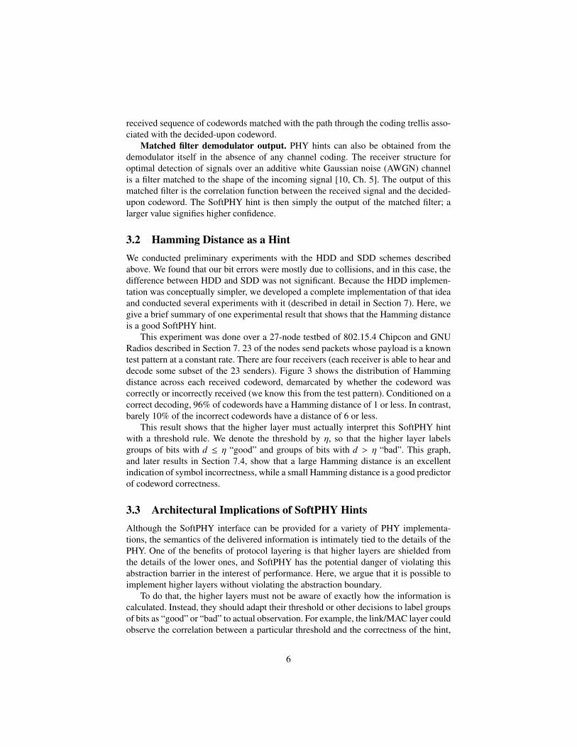
Figure 16: Packet sizes of partial retransmissions between a pair of nodes transferringdata with PP-ARQ. Here each packet size is 250 bytes.
7.5 PP-ARQWe now present some preliminary results from our implementation of PP-ARQ. In thissingle-link experiment, one GNU Radio transmitter sent 250 byte data packets back-to-back to another GNU Radio receiver using the same DSSS/MSK modulation as inthe previous results.
Figure 16 shows the sizes of each retransmission packet that the PP-ARQ sendersent to the PP-ARQ receiver. We see that even in this implementation, which has yetto be performance-tuned, the median retransmission size is approximately half the fullpacket size. This implies that in a busy network, PP-ARQ may need to retransmit atmost half the data, on half the total retransmissions.
8 Related WorkWhile each of the three ideas in PPR—SoftPHY, postamble decoding, and PP-ARQ—is novel, as is their synthesis into a single system, these individual ideas are related toand inspired by much previous work. We survey closely related work in this section.
8.1 Work Related to SoftPHYThe Viterbi algorithm for convolutional decoding has been extended with a “soft” out-put that indicates the reliability of the output decision: the result is the soft-outputViterbi algorithm (SOVA) [11], a component of the Turbo decoder [4]. The formerwork proposes the use of SOVA in the decoding of outer codes and is contained withinthe physical layer, whereas our focus is on constructing and propagating hints to higherlayers. The two techniques are complementary, because layered coding could be usedin conjunction with SoftPHY as long as the outer-layer code outputs a confidence met-ric.
22

8.2 Work Related to Postamble DecodingSince the body of a DSSS-modulated packet is composed of a known spreading se-quence, Jeong and Lehnart propose using all of the packet for acquisition [13]. Ourwork builds on this idea by using similar postamble-based techniques to not only im-prove the probability of acquisition, but also recover from partial collisions more effi-ciently.
Whitehouse et al. [29] and Priyantha [23] propose avoiding “undesirable capture”in packet-based wireless networks in time. Undesirable capture occurs when the weakerof two packets arrives first at a receiving node, so that the stronger, later packet corruptsthe weaker, earlier packet, resulting in neither being decoded correctly. This can beviewed as a special case of postamble decoding, which we fully explore in the presentwork.
8.3 Wireless Error ControlAhn et al. [2] propose an adaptive FEC algorithm which dynamically adjusts theamount of FEC coding per packet based on the presence or absence of receiver ac-knowledgements.
Hybrid ARQ is the combining of the two basic schemes of forward error control(FEC) and automatic repeat request (ARQ). Type I hybrid ARQ schemes [16] retrans-mit the same coded data in response to receiver NACKs. Chase combining [7] improveson this strategy by storing corrupted packets and feeding them all to the decoder. TypeII hybrid ARQ schemes [16] forego aggressive FEC while the channel is quiet, andsend parity bits on retransmissions, a technique called incremental redundancy [18].Metzner [19] and later Lin and Yu [17] have developed type II hybrid ARQ schemesbased on incremental redundancy.
PP-ARQ takes a different approach from the above work: instead of using strongercodes for the entire packet on retransmit, it uses hints from the physical layer aboutwhich codewords are more likely to be in error, and retransmits just those codewords.
Techniques such as coding with interleaving [10, Chp. 8] spread the bursts of errorsassociated with collisions and deep fades across many codewords so that they can becorrected. This technique is complementary to partial packet recovery, but not easy toimplement, because it is necessary to know the channel conditions rate a priori in orderto provision the amount of coding required to acheieve high throughput.
8.4 High-Throughput Wireless ProtocolsRate selection algorithms have been extensively studied in 802.11 wireless net-works [5, 12, 14, 24]. As with adjusting the amount of coding on a wireless link, itis hard to predict how much redundancy a link will need in highly-variable conditions.PPR mitigates the need for choosing the correct rate by allowing receivers to recoverpartially-received frames and efficiently retransmit only the parts missing. Moreover,SoftPHY hints can potentially be used to perform rate adaptation at finer time-scalesthan before, because it is now possible for the MAC layer to estimate the symbol errorrate for different rates and modulations more directly than before.
23

SoftPHY and postamble decoding together also has the potential to improve theperformance of mesh network protocols such as opportunistic routing [6] and networkcoding. In both cases, nodes need only forward or combine (using XOR, say) symbols(groups of bits) that are likely to be correct, and avoid wasting network capacity on in-correct data. Rather than use PP-ARQ, the integrated MAC/link layer that implementsExOR or network coding would directly work with SoftPHY’s output. Alternatively,PP-ARQ could operate in the “background” recovering erroneous data, while the rout-ing protocol sends the correct bits forward.
Similarly, PPR has the potential to improve the performance of multi-radio diversity(MRD) schemes [20] in which multiple access points listen to a transmission and com-bine the data to recover errors before forwarding the result, saving on retransmissions.Avudainayagan [3, 30] et al.develop a scheme in which multiple nodes (e.g., accesspoints) exchange soft decision estimates of each data symbol and collaboratively usethat information to improve decoding performance. For this application, PPR’s Soft-PHY hints would provide a way to design a protocol that does not rely on the specificsof the PHY, unlike this previous work. Thus, with PPR, we may be able to obtain thesimpler design and PHY-independence of the block-based combining of [20], whilealso achieving the performance gains of using PHY information.
9 ConclusionThis paper described the design, implementation, and experimental evaluation of PPR,a system for partial packet recovery. The motivation for PPR is the observation thatwireless bit errors usually don’t corrupt all the bits in a packet. PPR incorporates threenovel techniques that work in concert: first, SoftPHY, which enhances the physicallayer to compute and pass confidence information about each group of demodulatedbits, and second, the postamble decoding scheme to recover bits even when a packet’spreamble has been corrupted (postamble decoding). The confidence information canhelp higher layers perform better, as shown in our third technique, PP-ARQ, whichshows how a receiver can use this information together with a dynamic programmingalgorithm to request the sender to re-send ranges of bits, rather than an entire packet.
We have implemented all three components on the GNU Radio platform for802.15.4, the Zigbee standard, and evaluated the components and system in a 25-nodeindoor testbed. Our results show a 2× improvement in throughput over the status quounder moderate load, and 7× improvement at high load when many links have marginalquality. Furthermore, our proposed SoftPHY hint, Hamming distance, is a useful mea-sure of bit correctness to PP-ARQ. Finally, PP-ARQ offers considerable savings inretransmission packet size.
We believe that PPR has the potential to change the way PHY, link, and MACprotocol designers think about protocols. Today’s wireless PHY implementations usesignificant redundancy to tolerate worst-case channel conditions. If noise or interfer-ence during the reception of some codewords is higher than expected, existing PHYimplementations will generate incorrect bits, which causing packet-level CRCs to fail.When that happens, entire packets have to be retransmitted. Since SINR depends onother concurrent transmissions and external sources, fluctuations in SINR are often
24

large. The penalty for incorrect decoding is also large. For these two reasons, PHYlayers tend to be conservative with coding and modulation and MAC layers tend to beconservative with rate adaptation. The prevailing mind-set is that the consequences ofbit errors are dire, and must be reduced (though eliminating them is impossible). As aresult, current systems operate at comparatively low payload bit-rates.
PPR reduces the penalty of incorrect decoding, and thus for a given environmentallows the amount of redundancy to be decreased, or equivalently the payload bit-rateto be increased. Put another way, with SoftPHY and PPR, it would be better for a PHYto use parameters that lead to a BER that is one or even two orders-of-magnitude higherthan done currently, because higher layers need no longer have to cope with high packeterror rates—they can decode and recover partial packets correctly.
In addition to investigating the above idea, our plans for future work include imple-menting other ways of obtaining confidence information (as outlined in Section 3, de-veloping a PHY-independent SoftPHY interface and showing how a PP-ARQ link layercan use different SoftPHY implementations without change, performing a broader setof experiments in more settings, and using SoftPHY information to improve the per-formance of routing protocols such as opportunistic routing [6].
References[1] AGUAYO, D., BICKET, J., BISWAS, S., JUDD, G., AND MORRIS, R. Link-
level measurements from an 802.11b mesh network. In Proc. ACM SIGCOMM(Portland, OR, Aug. 2004).
[2] AHN, J.-S., HONG, S.-W., AND HEIDEMANN, J. An Adaptive FEC Code Con-trol Algorithm for Mobile Wireless Sensor Networks. Journal of Communicationsand Networks 7, 4 (2005), 489–499.
[3] AVUDAINAYAGAM, A., SHEA, J. M., WONG, T. F., AND XIN, L. Reliabilityexchange schemes for iterative packet combining in distributed arrays. In Proc.of the IEEE WCNC (Mar. 2003), vol. 2, pp. 832–837.
[4] BERROU, C., GLAVIEUX, A., AND THITIMAJSHIMA, P. Near Shannon LimitError-Correcting Coding and Decoding: Turbo Codes. In Proc. of the IEEE ICCConf. (May 1993), pp. 54–83.
[5] BICKET, J. Bit-rate selection in wireless networks. Master’s thesis, Mas-sachusetts Institute of Technology, Feb. 2005.
[6] BISWAS, S., AND MORRIS, R. ExOR: Opportunistic multi-hop routing for wire-less networks. In ACM SIGCOMM 2005 (Aug. 2005).
[7] CHASE, D. Code combining: A maximum-likelihood decoding approach forcombining an arbitrary number of noisy packets. IEEE Trans. on Comm. 33, 5(May 1985), 385–393.
[8] EFSTATHIOU, D., FINES, P., AND H, A. A. Preamble-less non-decision-aided(NDA) techniques for 16-QAM carrier phase recovery and gain error correction,for burst transmissions. In Proc. of the IEEE GLOBECOMM Conf. (Nov. 1993),pp. 1090–1094.
[9] The GNU Radio Project. http://www.gnu.org/software/gnuradio/.
25

[10] GOLDSMITH, A. Wireless Communications. Cambridge Univ. Press, New York,NY, 2005.
[11] HAGENAUER, J., AND HOEHER, P. A Viterbi Algorithm with Soft-DecisionOutputs and its Applications. In Proc. of the IEEE GLOBECOM Conf. (Dallas,TX, Nov. 1989).
[12] HOLLAND, G., VAIDYA, N., AND BAHL, P. A rate-adaptive MAC protocol formulti-hop wireless networks. In ACM Mobicom 2001 (Sept. 2001).
[13] JEONG, Y., AND LEHNERT, J. Acquisition of Packets with a Short Preamble forDirect-Sequence Spread-Spectrum Multiple-Access Packet Communications. InProc. of IEEE MILCOM Conf. (2003), pp. 1060–1064.
[14] LACAGE, M., MANSHAEI, M. H., AND TURLETTI, T. IEEE 802.11 rate adap-tation: a practical approach. In Proc. of the ACM MSWiM Workshop (Oct. 2004),pp. 126–134.
[15] LEE, E., AND MESSERSCHMITT, D. Digital Communication. Kluwer AcademicPublishers, Boston, MA, 1988.
[16] LIN, S., AND COSTELLO, D. J. Error Control Coding, 2nd. ed. Prentice Hall,2004.
[17] LIN, S., AND YU, P. S. A Hybrid ARQ Scheme with Parity Retransmission forError Control of Satellite Channels. IEEE Trans. on Comm. 30, 7 (July 1982),1701–1719.
[18] MANDELBAUM, D. An Adaptive-Feedback Coding Scheme Using IncrementalRedundancy (Corresp.). IEEE Trans. on Information Theory 20, 3 (May 1974),388–389.
[19] METZNER, J. Improvements in Block-Retransmission Schemes. IEEE Trans. onComm. 27, 2 (Feb. 1979), 524–532.
[20] MIU, A., BALAKRISHNAN, H., AND KOKSAL, C. E. Improving loss resiliencewith multi-radio diversity in wireless networks. In ACM Mobicom (Aug. 2005).
[21] MUELLER, K., AND MÜLLER, M. Timing Recovery in Digital SynchronousData Receivers. IEEE Trans. on Comm. 24, 5 (May 1976).
[22] PASUPATHY, S. Minimum Shift Keying: A Spectrally-Efficient Modulation.IEEE Communications Magazine 7, 4 (July 1979), 14–22.
[23] PRIYANTHA, N. B. The Cricket Indoor Location System. PhD thesis, MIT, May2005.
[24] SADEGHI, B., KANODIA, V., SABHARWAL, A., AND KNIGHTLY, E. Oppor-tunistic media access for multirate ad hoc networks. In Proceedings of ACMMobicom 2002 (September 2002).
[25] SCHMID, T. Personal communication. Also see code repository athttp://acert.ir.bbn.com/projects/gr-ucla/.
[26] SON, D., KRISHNAMACHARI, B., AND HEIDEMANN, J. Experimental Analysisof Concurrent Packet Transmissions in Low-Power Wireless Networks. In SenSys(Boulder, CO, Nov. 2006).
[27] SRINIVASAN, K., DUTTA, P., TAVAKOLI, A., AND LEVIS, P. Understandingthe Causes of Packet Delivery Success and Failure in Dense Wireless Sensor Net-works. Tech. Rep. SING-06-00, Stanford Univ., 2006.
[28] TI/Chipcon Products CC2420 Data Sheet.http://www.chipcon.com/files/CC2420_Data_Sheet_1_3.pdf.
26

[29] WHITEHOUSE, K., WOO, A., JIANG, F., POLASTRE, J., AND CULLER, D. Ex-ploiting the Capture Effect for Collision Detection and Recovery. In IEEE EmNetsWorkshop (Sydney, Australia, May 2005).
[30] WONG, T. F., XIN, L., AND SHEA, J. M. Iterative decoding in a two-node dis-tributed array. In Proc. of the IEEE MILCOM Conf. (Oct. 2002), vol. 2, pp. 1320–1324.
27
