powerflex 753 vfd fault codes - wireless...
TRANSCRIPT

Page 1 of 1
Application Note: PowerFlex 753 Fault Codes Version 001 01 May 2018
PowerFlex 753 Fault Codes If a FAULT has occurred, and you are at the TELEMETRY USER INTERFACE:
1. Note the FAULT CODE in the TELEMETRY USER INTEFACE. 2. Turn all VFD’s OFF via the TELEMETRY USER INTERFACE. 3. Address the condition that caused the FAULT.
See Table Below For List of Fault Codes and Descriptions. The cause must be corrected before the fault can be cleared. Corrective action may require a troubleshooting/repair visit to the VFD site.
4. After corrective action has been take, clear the fault by: Modify Station Setpoints with a CHECKMARK in the setting: “RESET_VFD_ONESHOT”.
5. To resume normal operation, turn all VFD’s back to AUTO via the TELEMETRY USER INTERFACE.
If a FAULT has occurred, and you are at the KEYPAD:
1. See Table Below For List of Fault Codes and Descriptions.
2. Turn all VFD’s OFF via the TELEMETRY USER INTERFACE or via Control Panel.
3. Press RESET_BUTTON on the KEYPAD to acknowledge the FAULT. The fault information will be removed so that you can resume using the keypad.
4. Address the condition that caused the FAULT. The cause must be corrected before the fault can be cleared.
5. After corrective action has been take, clear the fault by:
Press STOP at the KEYPAD ..or.. Cycle VFD Power (VFD shutdown may take up to 1 minute to discharge capacitor energy).
6. To resume normal operation, turn all VFD’s back to AUTO via the TELEMETRY USER INTERFACE or via the Control Panel.

Troubleshooting Chapter 6
Drive Fault and Alarm Descriptions
Table 10 contains a list of drive-specific faults and alarms and includes the following information:
• The fault or alarm type• The action that is taken when the drive faults• The parameter that is used to configure the fault or alarm (if applicable)• A description and action (where applicable)
The faults and alarms that are listed in Table 10 only apply to non-Integrated Motion applications. See Table 39 on page 527 for a list of Integrated Motion faults.
Table 10 - Drive Fault and Alarm Types, Descriptions, and Actions
Event No.
Fault/Alarm Text Type Fault Action
Configuration Parameter
Auto Reset
Description/Action(s)
0 No Entry
2 Auxiliary Input Resettable Fault Coast 157 [DI Aux Fault] Y An auxiliary input interlock is open. A condition within the application is not allowing the drive to energize the motor and the digital input that is assigned in P157 [DI Aux Fault] has forced this fault.
3 Power Loss Configurable 449 [Power Loss Actn] Y The DC bus voltage remained below the [Pwr Loss n Level] of nominal for longer than the time programmed in [Pwr Loss n Time].
4 UnderVoltage Configurable 460 [UnderVltg Action] Y If the bus voltage indicated in P11 [DC Bus Volts] falls below the value set in P461 [UnderVltg Level] an undervoltage condition exists.
5 OverVoltage Resettable Fault Coast Y The DC bus voltage exceeded the maximum value.See P11 [DC Bus Volts].
7 Motor Overload Configurable 410 [Motor OL Actn] Y An internal electronic overload trip has occurred.See P7 [Output Current], P26 [Motor NP Amps, P413 [Mtr OL Factor], and/or P414 [Mtr OL Hertz].
8 Heatsink OvrTemp Resettable Fault Coast Y The heatsink temperature has exceeded 100 % of the drive temperature.Heatsink over temperature occurs between 115…120 °C. The exact value is stored in drive firmware.See P943 [Drive Temp Pct] and/or P944 [Drive Temp C].
9 Trnsistr OvrTemp Resettable Fault Coast Y The output transistors have exceeded the maximum operating temperature.See P941 [IGBT Temp Pct] and/or P942 [IGBT Temp C].If using the drive on a chiller plate, P38 [PWM Frequency] must be set to 2 kHz.
10 DynBrake OvrTemp Alarm 1 The dynamic brake resistor has exceeded its maximum operating temperature.Check settings of parameters P382 [DB Resistor Type] through P385 [DB ExtPulseWatts].
12 HW OverCurrent Resettable Fault Coast Y The drive output current has exceeded the hardware current limit.Insulation Resistance (IR) test the wiring to motor.
13 Ground Fault Resettable Fault Coast Y A current path to earth ground greater than 25 % of drive rating has occurred.
14 Ground Warning Configurable 466 [Ground Warn Actn] The ground current has exceeded the level set in P467 [Ground Warn Lvl].
15 Load Loss Configurable 441 [Load Loss Action] The output torque current is below the value programmed in P442 [Load Loss Level] for a time period greater than the time programmed in P443 [Load Loss Time].
Rockwell Automation Publication 750-PM001N-EN-P - February 2017 309

Chapter 6 Troubleshooting
17 Input Phase Loss Configurable 462 [InPhase LossActn] The DC bus ripple has exceeded a preset level. Make these checks and adjustments in this order.• Check input impedance balance.• Increase the setting of P463 [InPhase Loss Lvl] to make the drive
less sensitive.• Tune the bus regulator or speed regulator to mitigate the effects of
dynamic cyclic loads on DC bus ripple.• Disable the fault by setting P462 [InPhase LossActn] to 0 “Ignore”
and use an external phase loss detector such as a Bulletin 809S relay.
18 Motor PTC Trip Configurable 250 [PTC Cfg] Motor PTC (Positive Temperature Coefficient) over temperature.
19 Task Overrun Alarm 1 System resource utilization is at or above 90 % of capacity. Review the system resource allocation table on page 307.
20 TorqPrv Spd Band Resettable Fault Coast The difference between P2 [Commanded SpdRef] and P3 [Mtr Vel Fdbk] has exceeded the level programmed in P1105 [Speed Dev Band] for a time period greater than the time programmed in P1106 [SpdBand Intgrtr].
21 Output PhaseLoss Configurable 444 [OutPhaseLossActn] The current in one or more phases has been lost or remains below the threshold set in P445 [Out PhaseLossLvl] for 1 second. Decreasing the threshold makes the drive less sensitive to tripping. A deceased threshold is necessary when the motor is smaller than the drive rating.If TorqProve™ is active, the current in one or more phases has been lost or remains below a threshold for five msecs. The phases are checked at start to be sure that torque is delivered to the load. If the drive is faulting on start, increase P44 [Flux Up Time].If TorqProve is active, and the brake is slipping, this fault occurs. When TorqProve is used, before the signal to the brake is applied to release it, the flux up time is used to check the three phases. The angle is adjusted to be sure that current is flowing through all three phases. If the motor moves during this test, the brake is not holding and a phase loss can occur.If TorqProve is active, and no brake is present, this fault occurs.Check for an open output contactor.
24 Decel Inhibit Configurable 409 [Dec Inhibit Actn] The drive is not following a commanded deceleration because it is attempting to limit the bus voltage.For high inertia loads, set P621 [Slip RPM at FLA] to 0 (V/Hz and SVC modes only).
25 OverSpeed Limit Resettable Fault Coast Y The motor operating speed exceeds the limit set by the maximum speed setting P524 [Overspeed Limit]. For forward motor rotation, this limit is P520 [Max Fwd Speed] + P524 [Overspeed Limit]. For reverse motor rotation, this limit is P521 [Max Rev Speed] - P524 [Overspeed Limit]. When flux vector control modes are selected in P35 [Motor Ctrl Mode], P131 [Active Vel Fdbk] determines the motor operating speed. For all other non-flux vector control modes, P1 [Output Frequency] determines the motor operating speed.
Event No.
Fault/Alarm Text Type Fault Action
Configuration Parameter
Auto Reset
Description/Action(s)
ATTENTION: If a PM motor is used and motor phase is lost, lower P445 [OutPhaseLossLvl] to 0 if TorqProve is not used or the drive output (motor) contacts are not used. Otherwise, lower P445 [OutPhaseLossLvl] until the drive is able to start and run without faulting.
310 Rockwell Automation Publication 750-PM001N-EN-P - February 2017

Troubleshooting Chapter 6
26 Brake Slipped Alarm 1 The encoder movement has exceeded the level in P1110 [Brk Slip Count] after the brake was set and the brake slip maneuver is controlling the drive. (Drive is active.) Cycle power to the drive to reset.
Alarm 2 The encoder movement has exceeded the level in P1110 [Brk Slip Count] after the brake was set and the brake slip maneuver is finished. (Drive is stopped.) Cycle power to the drive to reset.
27 Torq Prove Cflct Alarm 2 When P1100 [Trq Prove Cfg] is enabled, these parameters must be properly configured:• P35 [Motor Ctrl Mode]• P125 [Pri Vel Fdbk Sel] and P135 [Mtr Psn Fdbk Sel] must be set to
a valid feedback device. The feedback device does not have to be the same device. However, Open Loop and Simulation Feedback are not considered valid feedback devices.If parameters 125 and 135 are set to a feedback module, verify that the module parameters are set properly. On the module, the feedback loss action CANNOT be set to 0 “Ignore.” Does not work in PM FV mode. Does not work with single ended or channel A only encoders.
28 TP Encls Config Alarm 2 Encoderless TorqProve has been enabled but the application concerns of encoderless operation have not read and understood. Read the “Attention” on page 356 relating to the use of TorqProve with no encoder.
29 Analog In Loss Configurable 263 [Anlg In0 LssActn] Analog input has a lost signal.
33 AuRsts Exhausted Resettable Fault Coast 348 [Auto Rstrt Tries] The drive attempted to reset a fault and resume running for the programmed number of tries, unsuccessfully.
35 IPM OverCurrent Resettable Fault Coast The current magnitude has exceeded the trip level set by P1640 [IPM Max Cur]. Set this value to 0 only when the drive is set to the V/Hz or SVC mode.
36 SW OverCurrent Resettable Fault Coast Y The drive output current has exceeded the 1 ms current rating. This rating is greater than the 3 second current rating and less than the hardware overcurrent fault level. It is typically 200…250% of the drive continuous rating.
383940
Phase U to GrndPhase V to GrndPhase W to Grnd
Resettable Fault Coast A phase to ground fault has been detected between the drive and motor in this phase.Rotate U/T1, V/T2, W/T3 connections.• If the problem follows the wire, suspect a field wiring problem.• If no change, suspect a problem with the drive.
414243
Phase UV ShortPhase VW ShortPhase WU Short
Resettable Fault Coast Excessive current has been detected between these two output terminals.Rotate U/T1, V/T2, W/T3 connections.• If the problem follows the wire, suspect a field wiring problem.• If no change, suspect a problem with the drive.
444546
Phase UNegToGrndPhase VNegToGrndPhase WNegToGrnd
Resettable Fault Coast A phase to ground fault has been detected between the drive and motor in this phase.Rotate U/T1, V/T2, W/T3 connections.• If the problem follows the wire, suspect a field wiring problem.• If no change, suspect a problem with the drive.
48 System Defaulted Resettable Fault Coast The drive was commanded to write default values.
49 Drive Powerup – A Power Up Marker in the Fault Queue indicating that the drive power cycled.
51 Clr Fault Queue – Indication that the fault queue has been cleared.
55 Ctrl Bd Overtemp Resettable Fault Coast The temperature sensor on the main control board detected excessive heat. See product temperature requirement.
58 Module Defaulted Resettable Fault Coast The module was commanded to write default values.
59 Invalid Code Resettable Fault Coast Internal error.
61 Shear Pin 1 Configurable 435 [Shear Pin 1 Actn] Y The programmed value in P436 [Shear Pin1 Level] has been exceeded.
62 Shear Pin 2 Configurable 438 [Shear Pin 2 Actn] Y The programmed value in P439 [Shear Pin2 Level] has been exceeded.
Event No.
Fault/Alarm Text Type Fault Action
Configuration Parameter
Auto Reset
Description/Action(s)
Rockwell Automation Publication 750-PM001N-EN-P - February 2017 311

Chapter 6 Troubleshooting
64 Drive OverLoad Alarm 1 Y P940 [Drive OL Count] has exceeded 50 % but is less than 100 %.
Resettable Fault Coast P940 [Drive OL Count] has exceeded 100 %. Reduce the mechanical load on the drive.Inverter fiber-optic connection is not detected on Frame 8 drive.This fault can occur on power-up if the control detects that no inverter is detected via the fiber-optic communication on a Frame 8 drive.
67 Pump Off Alarm 1 Pump Off condition has been detected.
717273747576
Port 1 AdapterPort 2 AdapterPort 3 AdapterPort 4 AdapterPort 5 AdapterPort 6 Adapter
Resettable Fault Coast The DPI communications option has a fault.See device event queue.
77 IR Volts Range Alarm 2 The value for P73 [IR Voltage Drop], which is calculated from the motor nameplate data, is not within the range of acceptable values, as determined by the Calculated Autotune procedure.Check the motor nameplate data against parameters P25 [Motor NP Volts] through P30 [Motor NP Power].
Resettable Fault Coast The measured value for P73 [IR Voltage Drop] is not within the range of acceptable values, as determined by the Static or Rotate Autotune procedure.
78 FluxAmpsRef Rang Alarm 2 The value for flux amps exceeds the value programmed in P26 [Motor NP Amps], as calculated by the Autotune procedure.Check motor nameplate data against parameters P25 [Motor NP Volts] through P30 [Motor NP Power].
Resettable Fault Coast The value for flux amps exceeds the value programmed in P26 [Motor NP Amps], as measured by the Static or Rotate Autotune procedure.
79 Excessive Load Resettable Fault Coast The motor did not come up to speed in the allotted time during Autotune.
80 AutoTune Aborted Resettable Fault Coast The Autotune function was manually canceled or a fault occurred.
818283848586
Port 1 DPI LossPort 2 DPI LossPort 3 DPI LossPort 4 DPI LossPort 5 DPI LossPort 6 DPI Loss
Resettable Fault Coast 324 [Logic Mask] The DPI port stopped communicating.Check connections and drive grounding.
87 IXo VoltageRange Alarm 2 The default for P70 [Autotune] is 1 “Calculate” and the voltage that is calculated for motor inductive impedance exceeds 25 % of the value of P25 [Motor NP Volts].
Resettable Fault Coast P70 [Autotune] is set to 2 “Static Tune” or 3 “Rotate Tune” and the voltage that is measured for motor inductive impedance exceeds 25 % of the value of P25 [Motor NP Volts].
91 Pri VelFdbk Loss Configurable Note: See option module for configuration parameter number
A Feedback Loss has been detected for the source of P127 [Pri Vel Feedback]. The feedback loss could be due to a problem detected by the feedback option module selected by P125 [Pri Vel Fdbk Sel] or due to a loss in communication between the feedback option module and main control board. The source of primary velocity feedback must be configured not to fault if the feedback loss switchover feature is used.
93 Hw Enable Check Resettable Fault Coast The hardware enable is disabled (a jumper is installed) but indicates not enabled.
94 Alt VelFdbk Loss Configurable Note: See option module for configuration parameter number
A Feedback Loss has been detected for the source of P128 [Alt Vel Fdbk Sel]. The feedback loss could be due to a problem detected by the feedback option module selected by P128 [Alt Vel Fdbk Sel], or due to a loss in communication between the feedback option module and main control board.
Event No.
Fault/Alarm Text Type Fault Action
Configuration Parameter
Auto Reset
Description/Action(s)
312 Rockwell Automation Publication 750-PM001N-EN-P - February 2017

Troubleshooting Chapter 6
95 Aux VelFdbk Loss Configurable Note: See option module for configuration parameter number
A Feedback Loss has been detected for the source of P132 [Aux Vel Fdbk Sel]. The feedback loss could be due to a problem detected by the feedback option module selected by P132 [Aux Vel Fdbk Sel], or due to a loss in communication between the feedback option module and main control board.
96 PositionFdbkLoss Configurable Note: See option module for configuration parameter number
A Feedback Loss has been detected for the source of P847 [Psn Fdbk]. The feedback loss could be due to a problem detected by the feedback option module selected by P135 [Mtr Psn Fdbk Sel], or due to a loss in communication between the feedback option module and main control board.
97 Auto Tach Switch Resettable Fault Coast 635 [Spd Options Ctrl]Bit 7 “Auto Tach SW”
Indication that either of the two following conditions exists.• Tach switch has occurred and alternate feedback device has failed.• Tach switch has not occurred, Auto Tach Switch Option is enabled
and both primary and alternate devices have failed.
100 Parameter Chksum Resettable Fault Coast The checksum read from the non-volatile storage does not match the checksum calculated. The data is set to the default value.
101 PwrDn NVS Blank Resettable Fault Coast Internal data error.• Reset parameter defaults. See publication 20HIM-UM001 for
instructions.• Reload parameters.• If problem persists, replace main control board.Fault normally occurs after a flash update to correct F117 fault.
102 NVS Not Blank Resettable Fault Coast Internal data error.
103 PwrDn NVS Incomp Resettable Fault Coast Internal data error.
104 Pwr Brd Checksum Non-Reset Fault The checksum read from the non-volatile storage does not match the checksum calculated. The data is set to the default value.
106 Incompat MCB-PB Non-Reset Fault Coast The main control board did not recognize the power structure. Flash with newer Application revision.
107 Replaced MCB-PB Resettable Fault Coast The main control board was moved to another power structure. The data is set to the default values.
108 Anlg Cal Chksum Non-Reset Fault Coast The checksum read from the analog calibration data does not match the checksum calculated. Replace main control board.
110 Ivld Pwr Bd Data Non-Reset Fault Coast Power structure data invalid.• Verify ribbon cable connection between the main control board
and the power interface board.• Replace power interface board.
111 PwrBd Invalid ID Non-Reset Fault Coast Power structure ID invalid.• Verify ribbon cable connection between the main control board
and the power interface board.• Replace power interface board.
112 PwrBd App MinVer Resettable Fault Coast Power structure needs newer Application revision. Flash with newer Application revision.
113 Tracking DataErr Resettable Fault Coast Internal data error.
115 PwrDn Table Full Resettable Fault Coast Internal data error.
116 PwrDnEntry2Large Resettable Fault Coast Internal data error.
117 PwrDn Data Chksm Resettable Fault Coast Internal data error.
118 PwrBd PwrDn Chks Resettable Fault Coast Internal data error.
124 App ID Changed Resettable Fault Coast Application Firmware changed. Verify Application revision.
125 Using Backup App Resettable Fault Coast Application did not flash correctly. Reflash.
134 Start On PowerUp Alarm 1 When P345 [Start At PowerUp] is enabled, an alarm is set for the time programmed in P346 [PowerUp Delay].
137 Ext Prechrg Err Configurable 323 [Prchrg Err Cfg] The seal contact on the external precharge contactor has opened (as signalled by P190 [DI Prchrg Seal]) while the drive was running (PWM was active).
Event No.
Fault/Alarm Text Type Fault Action
Configuration Parameter
Auto Reset
Description/Action(s)
Rockwell Automation Publication 750-PM001N-EN-P - February 2017 313

Chapter 6 Troubleshooting
138 Precharge Open Resettable Fault Coast 321 [Prchrg Control]190 [DI Prchrg Seal]189 [DI Precharge]
The internal precharge was commanded to open while the drive was running (PWM was active). The internal fault latch is automatically cleared when PWM is disabled.
141 Autn Enc Angle Resettable Fault Coast P78 [Encdrlss AngComp] is out of range.
142 Autn Spd Rstrct Resettable Fault Coast Frequency limit settings are preventing the drive from reaching a suitable speed during an Inertia Tune test.
143 Autotune CurReg Resettable Fault Coast Calculated values for P96 [VCL Cur Reg Kp] and/or P97 [VCL Cur Reg Ki] are out of range.
144 Autotune Inertia Resettable Fault Coast Results from the Inertia Tune test out of range for P76 [Total Inertia].
145 Autotune Travel Resettable Fault Coast When P77 [Inertia Test Lmt] is set, the Inertia Tune test was prevented from reaching a suitable speed to run the test.
152 No Stop Source Resettable Fault Coast Last stop source has been removed.
155 Bipolar Conflict Alarm 2 P308 [Direction Mode] is set to 1 “Bipolar” or 2 “Rev Disable” and one or more digital inputs is enabled for direction control.
157 DigIn Cfg B Alarm 2 Digital input conflict. Input functions that cannot exist simultaneously have been selected (for example run and start). Correct Digital Input configuration.
Digital Input combinations marked “•” cause an alarm.
Event No.
Fault/Alarm Text Type Fault Action
Configuration Parameter
Auto Reset
Description/Action(s)
DI St
op M
ode B
DI Sp
eed S
el 2
DI Sp
eed S
el 1
DI Sp
eed S
el 0
DI M
anua
l Ctrl
DI D
ecel
2
DI Ac
cel 2
DI Fw
d Rev
erse
DI Jo
g 2 Re
verse
DI Jo
g 2 Fo
rwar
d
DI Jo
g 2
DI Jo
g 1 Re
verse
DI Jo
g 1 Fo
rwar
d
DI Jo
g 1
DI Ru
n Rev
erse
DI Ru
n For
ward
DI Ru
n
DI St
art
DI H
OA St
art
DI Cl
ear F
ault
DI Au
x Fau
lt
DI Cu
r Lm
t Sto
p
DI Co
ast S
top
DI St
op
DI Stop
DI Coast Stop
DI Cur Lmt Stop
DI Aux Fault • •DI Clear Fault •DI HOA Start • • • • • • • • • •DI Start • • • • • • • • •DI Run • • • • • • • •DI Run Forward • • • • • •DI Run Reverse • • • • • •DI Jog 1 • • • • • •DI Jog 1 Forward • • • • • •DI Jog 1 Reverse • • • • • •DI Jog 2 • • • • • •DI Jog 2 Forward • • • • • •DI Jog 2 Reverse • • • • • •DI Fwd Reverse • • • • • •DI Accel 2
DI Decel 2
DI Manual Ctrl
DI Speed Sel 0
DI Speed Sel 1
DI Speed Sel 2
DI Stop Mode B
314 Rockwell Automation Publication 750-PM001N-EN-P - February 2017

Troubleshooting Chapter 6
158 DigIn Cfg C Alarm 2 Digital input conflict. Input functions that cannot be assigned to the same digital input have been selected (for example run and stop). Correct Digital Input configuration.
Digital Input combinations marked “•” cause an alarm.
161 Sleep Config Alarm 2 There is a Sleep/Wake configuration error. With Sleep Wake Mode = Direct, possible causes include:Drive is stopped and Wake Level < Sleep Level.Stop=CF, Run, Run Fwd, or Run Rev is not configured in Digital Input functions.
162 Waking Alarm 1 The Wake timer is counting toward a value that starts the drive.
168 HeatSinkUnderTmp Resettable Fault Heatsink temperature sensor is reporting a value below -18.7 °C (-1.66 °F) or the sensor feedback circuit is open.See P943 [Drive Temp Pct] and/or P944 [Drive Temp C].
169 PWM Freq Reduced Alarm 1 The PWM Frequency has been reduced from the value set in P38 [PWM Frequency] due to excessive IGBT junction temperatures.See also P420 [Drive OL Mode].
170 CurLimit Reduced Alarm 1 The current limit value has been reduced from the value set in [Current Limit n] due to excessive IGBT junction temperatures or P940 [Drive OL Count] = 95 %.See also P420 [Drive OL Mode].
Event No.
Fault/Alarm Text Type Fault Action
Configuration Parameter
Auto Reset
Description/Action(s)
DI St
op M
ode B
DI Sp
eed S
el 2
DI Sp
eed S
el 1
DI Sp
eed S
el 0
DI M
anua
l Ctrl
DI D
ecel
2
DI Ac
cel 2
DI Fw
d Rev
erse
DI Jo
g 2 Re
verse
DI Jo
g 2 Fo
rward
DI Jo
g 2
DI Jo
g 1 Re
verse
DI Jo
g 1 Fo
rward
DI Jo
g 1
DI Ru
n Rev
erse
DI Ru
n For
ward
DI Ru
n
DI St
art
DI H
OA St
art
DI Cl
ear F
ault
DI Au
x Fau
lt
DI Cu
r Lm
t Sto
p
DI Co
ast S
top
DI St
op
DI Stop • • • • • • • • • • • • • • • • • • • •DI Coast Stop • • • • • • • • • • • • • • • • • • • •DI Cur Lmt Stop • • • • • • • • • • • • • • • • • • • •DI Aux Fault • • • • • • • • • • • • • • • • • • • • • •DI Clear Fault • • • • • • • • • • • • • • • • • •DI HOA Start • • • • • • • • • • • •DI Start • • • • • • • • • • • •DI Run • • • • • • • • • • • • • •DI Run Forward • • • • • • • • • • • • • • • •DI Run Reverse • • • • • • • • • • • • • • • •DI Jog 1 • • • • • • • • • • •DI Jog 1 Forward • • • • • • • • • • • • • • • •DI Jog 1 Reverse • • • • • • • • • • • • • • • •DI Jog 2 • • • • • • • • • • •DI Jog 2 Forward • • • • • • • • • • • • • • • •DI Jog 2 Reverse • • • • • • • • • • • • • • • •DI Fwd Reverse • • • • • • • • • • • • • • • •DI Accel 2 • • • • • • • • • • • • • • • • • • • • •DI Decel 2 • • • • • • • • • • • • • • • • • • • • •DI Manual Ctrl • • • • • • • • • • • • • • • • • •DI Speed Sel 0 • • • • • • • • • • • • • • • • • • • • • •DI Speed Sel 1 • • • • • • • • • • • • • • • • • • • • • •DI Speed Sel 2 • • • • • • • • • • • • • • • • • • • • • •DI Stop Mode B
Rockwell Automation Publication 750-PM001N-EN-P - February 2017 315

Chapter 6 Troubleshooting
171 Adj Vltg Ref Alarm 1 Invalid adjustable-voltage reference selection conflict.
175 Travel Lim Cflct Non-Reset Fault Current Limit Stop
Travel limits are in conflict. Both the forward and reverse travel limits indicate that they are simultaneously active.If digital limits (hardware signals) are in use, ensure that the following forward and reverse digital input pairs are not both off simultaneously: fwd/rev decel travel limit digital inputs and fwd/rev end stop travel limit digital inputs. The travel limit digital inputs are meant to be connected to normally closed switch contacts, so the digital input status reads an off (0 = False) bit status when the machine is on limit and the switch contact opens. A possible cause for this condition is loss of common power to both the forward and reverse travel limit switches.If software travel limits are in use, check the state of the fwd/rev travel limit bits in P1101 [Trq Prove Setup]. These bits read an on (1 = Enabled) bit status when the machine is on limit. Bit 2 “Decel Fwd” and Bit 4 “Decel Rev” should not be on simultaneously. Similarly, Bit 3 “End Stop Fwd” and Bit 5 “End Stop Rev” should not be on simultaneously.
177 Profiling Active Alarm 1 The Profile/Indexer is active.
178 Homing Active Alarm 1 The Homing function is active.
179 Home Not Set Alarm 1 The Home position was not set before profile operation.
181 Fwd End Limit Resettable Fault Current Limit Stop
The selected digital input for one of the end limit switches, P196 [DI Fwd End Limit] or P198 [DI Rev End Limit], has detected a falling edge and P313 [Actv SpTqPs Mode] is not set to 1 “Speed Reg.”If digital limits (hardware signals) are in use, ensure that the digital inputs are connected to normally closed contacts. When the end limit is reached the contacts open.
182 Rev End Limit Resettable Fault Current Limit Stop
The selected digital input for one of the end limit switches, P196 [DI Fwd End Limit] or P198 [DI Rev End Limit], has detected a falling edge and P313 [Actv SpTqPs Mode] is not set to 1 “Speed Reg.”If digital limits (hardware signals) are in use, ensure that the digital inputs are connected to normally closed contacts. When the end limit is reached the contacts open.
185 Freq Conflict Alarm 2 Indicates that the values of P520 [Max Fwd Speed] and P521 [Max Rev Speed] are in conflict with the value of P63 [Break Frequency].
186 VHz Neg Slope Alarm 2 Indicates that the V/Hz curve segment resulted in a negative V/Hz slope.See P60 [Start Acc Boost] through P63 [Break Frequency].
187 VHz Boost Limit Alarm 2 Indication that one of the two following conditions exists.• P60 [Start/Acc Boost] and P61 [Run Boost] are greater than P25
[Motor NP Volts] x 0.25 when P65 [VHz Curve] = 0 “Custom V/Hz.”• P61 [Run Boost] is greater than P25 [Motor NP Volts] x 0.25 when
P65 [VHz Curve] = 1 “Fan/Pump.”
190 PM FV Pri Fdbk Alarm 2 Indicates a control mode and primary-feedback device configuration error. P35 [Motor Ctrl Mode] is set to the permanent magnet flux vector “PM FV” control mode, P125 [Pri Vel Fdbk Sel] is set to P137 [Open Loop Fdbk] (port 0).
191 PM FV Alt Fdbk Alarm 2 Indicates a control mode and alternate-feedback device configuration error. P35 [Motor Ctrl Mode] is set to the permanent magnet flux vector “PM FV” control mode, P635 [Spd Options Ctrl] is set to bit 7 “Auto Tach SW,” P128 [Alt Vel Fdbk Sel] is set to P137 [Open Loop Fdbk] (port 0).
192 Fwd Spd Lim Cfg Alarm 2 The forward speed reference is out of range.Verify the settings of P38 [PWM Frequency] and P520 [Max Fwd Speed]. Lower carrier frequencies reduce the output frequency range.Verify that P522 [Min Fwd Speed] is less than or equal to P520 [Max Fwd Speed].
Event No.
Fault/Alarm Text Type Fault Action
Configuration Parameter
Auto Reset
Description/Action(s)
316 Rockwell Automation Publication 750-PM001N-EN-P - February 2017

Troubleshooting Chapter 6
193 Rev Spd Lim Cfg Alarm 2 The reverse speed reference is out of range.Verify the settings of P38 [PWM Frequency] and P521 [Max Rev Speed]. Lower carrier frequencies reduce the output frequency range.Verify that P523 [Min Rev Speed] is greater than or equal to P521 [Max Rev Speed].
194 PM Offset Conflict Alarm 2 Both P80 [PM Cfg] bit 0 “AutoOfstTest” and bit 2 “StaticTestEn” are set. Select only one.
195 IPMSpdEstErr Resettable Fault Coast Speed Estimator failed to track High-Speed angle.
196 PM FS Cflct Alarm 2 Attempted to set P356 [FlyingStart Mode] to 2 “Sweep” with a permanent magnet motor selected in P35 [Motor Ctrl Mode].
197 PM Offset Failed Resettable Fault Coast Indicates that the PM Offset test failed due to interruption of the test before completion or the motor movement failed to reach the proper amount of rotation during the test. The test is rescheduled when this fault occurs. If failure occurred because of movement limitations, increase the [PM OfstTst Cur]. If this solution fails to correct the problem, the load on the motor maybe too large.
201 SpdReg DL Err Alarm 2 Attempted to establish a Datalink to P644 [Spd Err Flt BW], P645 [Speed Reg KP], or P647 [Speed Reg Ki] and P636 [Speed Reg BW] is set to a value other than zero.
202 AltSpdReg DL Err Alarm 2 Attempted to establish a Datalink to P649 [Alt Speed Reg Kp], P650 [Alt Speed Reg Ki], or P651 AltSpdErr FltrBW] and P648 [Alt Speed Reg BW] is set to a value other than zero.
203 Port 13 Adapter Resettable Fault Coast The embedded EtherNet/IP adapter has a fault. See EtherNet event queue.
204 Port 14 Adapter Resettable Fault Coast The DeviceLogix adapter has a fault.
205 DPI TransportErr Alarm 1 A DPI Communication Error has occurred.
210 HW Enbl Jmpr Out Resettable Fault Coast A Safety Option module is present and ENABLE Jumper is removed. Install the jumper. This fault occurs only on frames 1…7.
211 Safety Brd Fault Resettable Fault Coast A Safety option module has indicated a fault. Verify that ENABLE Jumper is installed. Reset or power cycle drive.Safe Speed Monitor (20-750-S1):• See P67 [Fault Status] on page 298 for more information on the
fault statuses.• See publication 750-RM001 for more information.Safe Torque Off (20-750-S):• If DC power drops below 17V DC “Not Enable” is indicated.• If voltage drops below 11V DC the module faults.• See publication 750-UM002 for more information.ATEX (20-750-ATEX):• Possible hardware damage.• The motor to the thermal sensor is shorted.• Excessive EMC noise due to improper grounding/shielding.• See publication 750-UM003 for more information.
212 Safety Jmpr Out Resettable Fault Coast SAFETY Jumper is not installed and a Safety option module is not present. Install the jumper.
213 Safety Jumper In Resettable Fault Coast SAFETY Jumper is installed and a Safety option module is present. Remove the jumper.
214 SafetyPortCnflct Alarm 2 Allowable number of safety options exceeded. Only one safety option module can be installed at a time.
Event No.
Fault/Alarm Text Type Fault Action
Configuration Parameter
Auto Reset
Description/Action(s)
Rockwell Automation Publication 750-PM001N-EN-P - February 2017 317

Chapter 6 Troubleshooting
224225226227228229230231232233234
Port 4 Comm LossPort 5 Comm LossPort 6 Comm LossPort 7 Comm LossPort 8 Comm LossPort 9 Comm LossPort10 Comm LossPort11 Comm LossPort12 Comm LossPort13 Comm LossPort14 Comm Loss
Resettable Fault Coast The device at the port has stopped communicating with the main control board.Verify that the device is present and functional.Verify network connections.Verify options that are installed in ports 4…8 are seated in the port and secured with mounting screws.
244245246247248249250251252253254
Port 4 CfgPort 5 CfgPort 6 CfgPort 7 CfgPort 8 CfgPort 9 CfgPort 10 CfgPort 11 CfgPort 12 CfgPort 13 CfgPort 14 Cfg
Alarm 2 The main control board does not have the correct option in the port.Option may not be compatible with product or MCB firmware must be updated to support it. Option may have to be moved or removed, accept option configuration change.
264265266267268269270271272273274
Port 4 ChecksumPort 5 ChecksumPort 6 ChecksumPort 7 ChecksumPort 8 ChecksumPort 9 ChecksumPort10 ChecksumPort11 ChecksumPort12 ChecksumPort13 ChecksumPort14 Checksum
Resettable Fault Coast An option module storage checksum failed.Option data has been set to default values.
281 Enet Checksum Resettable Fault Coast EtherNet/IP storage checksum failed. Data set to default values.
282 DLX Checksum Resettable Fault Coast DeviceLogix storage checksum failed. Data set to default values.
290 Prev Maint Reset Alarm 1 Predictive maintenance function has reset an elapsed life parameter.
291 HSFan Life Configurable 493 [HSFan EventActn] Predictive maintenance function has reached the event level. Perform maintenance.292 InFan Life Configurable 500 [InFan EventActn]
293 MtrBrng Life Configurable 506 [MtrBrngEventActn]
294 MtrBrng Lube Configurable 510 [MtrLubeEventActn]
295 MachBrng Life Configurable 515 [MtrBrngEventActn]
296 MachBrng Lube Configurable 519 [MchLubeEventActn]
307 Port7InvalidCard Non-Reset Fault Coast Option not valid in that port. Remove option module.
308 Port8InvalidCard Non-Reset Fault Coast
310 Regeneration OK Resettable Fault Coast The drive has detected that the 'Regeneration OK' input has transition to an ‘inactive’ state.
315 Excess Psn Err Configurable Configured with Logix controller.
The absolute maximum Position Error value has been exceeded.
318319320
OutCurShare PhUOutCurShare PhVOutCurShare PhW
Alarm 1 There is output current sharing imbalance between parallel inverters in the phase indicated that is greater than 15 % of the inverter rated current.
Event No.
Fault/Alarm Text Type Fault Action
Configuration Parameter
Auto Reset
Description/Action(s)
318 Rockwell Automation Publication 750-PM001N-EN-P - February 2017

Troubleshooting Chapter 6
322 N-1 Operation Alarm 1 20 (Port 10)[Recfg Acknowledg]21 (Port 10)[Effctv I Rating]
Drive is operating with fewer inverters than the original parallel configuration.
324 DC Bus Mismatch Non-Reset Fault Coast There is a bus voltage imbalance between parallel inverters that is greater than 50V DC.
327328329
HS Temp Imbal UHS Temp Imbal VHS Temp Imbal W
Alarm 1 There is a heatsink temperature imbalance between parallel inverters in the phase indicated that is greater than 11.5 °C (52.7 °F).
331332333
I1 Comm LossI2 Comm LossI3 Comm Loss
Resettable Fault Coast A communications fault has occurred between the main control board and the power layer interface board on inverter n.
341342343
C1 Comm LossC2 Comm LossC3 Comm Loss
Resettable Fault Coast A communications fault has occurred between the main control board and the converter gate board on converter n.
351352353
In Cur Share L1In Cur Share L2In Cur Share L3
Alarm 1 There is an input current sharing imbalance between parallel converters in the AC line indicated that is greater than 15 % of the converter rated current.
357358359
In Vlt Imbal L12In Vlt Imbal L23In Vlt Imbal L31
Alarm 1 There is an input line voltage imbalance between parallel converters in the AC lines indicated that is greater than 5 % of the converter rated voltage.
360 N-1 See Manual Resettable Fault Coast The number of active inverters has been reduced from the original parallel configuration.See N-1 and Re-Rate Functions on page 337.
361 Rerate See Manual Resettable Fault Coast The drive rating has changed from the original parallel configuration.See N-1 and Re-Rate Functions on page 337.
362 Cnv/Inv Mismatch Alarm 2 There is a voltage class mismatch between the installed parallel inverters and converters.
363 CBP/Inv Mismatch Alarm 2 There is a voltage class mismatch between the installed parallel inverters and common DC bus precharge units.
364 CBP Num Mismatch Alarm 2 The number of active inverters and active common DC bus precharge units does not match.
365 Zero Cnv/Prechrg Alarm 2 No converter or common DC bus precharge unit exists.
366 Cnv Num Mismatch Alarm 2 The number of active inverters and active converters does not match.
371372
P1 Comm LossP2 Comm Loss
Resettable Fault Coast A communications fault has occurred between the main control board and the DC precharge control board on the common DC bus precharge unit n.
380 PWM FPGA Overrun Alarm 1 The time limit on the PWM write to the FPGA was exceeded.
900 900 Automatic Drive Reset
Coast Critical input exception.Contact technical support.
901 Machine Check Automatic Drive Reset
Coast Internal error.Replace the main control board.
902 Data Storage Error Automatic Drive Reset
Coast Cache memory corrupt.Replace the main control board.
903 Instruction Storage Error Automatic Drive Reset
Coast Cache memory corrupt.Replace the main control board.
905 Alignment Error Automatic Drive Reset
Coast Pointer is pointing to a non-boundary member.Obtain test points and check grounding.
906 Program Error Automatic Drive Reset
Coast Bad memory read.Check grounding or replace the main control board.
Event No.
Fault/Alarm Text Type Fault Action
Configuration Parameter
Auto Reset
Description/Action(s)
Rockwell Automation Publication 750-PM001N-EN-P - February 2017 319

Chapter 6 Troubleshooting
907 Floating Point Unit Not On
Automatic Drive Reset
Coast Firmware issue.Obtain test points.
909 Aux Processor Not On Automatic Drive Reset
Coast Auxiliary processor interrupt.Contact technical support.
912 Watchdog Automatic Drive Reset
Coast The timer counted down, reached 0, and fault occurred.Replace the main control board.
913 Data TLB Error Automatic Drive Reset
Coast Processor attempted to access non-boundary memory.Check grounding or replace the main control board.
914 Instruction TLB Error Automatic Drive Reset
Coast Processor attempted to access non-boundary memory.Check grounding or replace the main control board.
916 FPGA Failed to Load Automatic Drive Reset
Coast MCB failed to load on powerup.Replace the main control board.
917 FPGA CRC Failure Resettable Fault (753)Disabled (755 LP)Automatic Drive Reset (755 HP)
Coast 964 [CRC Flt Cfg] only
Change fault configuration (753).Replace the main control board.
918 Control Task Overrun Automatic Drive Reset
Coast Carrier frequency changes when passing through 7 Hz.In P40 [Mtr Option Cfg], set the PWM to 2 kHz or turn on the “PWM FreqLock” Bit 9. Or flash the drive to 8.001.
919 System Task Overrun Automatic Drive Reset
Coast The control task not finished and being told to run again.If fault does not clear, replace the main control board.
920 5 mSec Task Overrun Automatic Drive Reset
Coast The control task not finished and being told to run again.If fault does not clear, replace the main control board.
921 Control Task Stall Automatic Drive Reset
Coast Control task stalled.Check grounding or replace the main control board.
922 System Task Stall Automatic Drive Reset
Coast System task stalled.Check grounding or replace the main control board.
923 5 mSec Task Stall Automatic Drive Reset
Coast 5 msec task stalled.Check grounding or replace the main control board.
924 Background Task Stall Automatic Drive Reset
Coast Background task stalled.Check grounding or replace the main control board.
925 Stack Overflow Automatic Drive Reset
Coast Firmware overflow.Obtain test points.
926 Ethernet Error Automatic Drive Reset
Coast Ethernet error.Contact technical support.
927 CIP Motion Error Automatic Drive Reset
Coast Integrated motion error.Contact technical support.
14037 Net IO Timeout Configurable 52 [DLX Prog Cond] DeviceLogix has been disabled.
Event No.
Fault/Alarm Text Type Fault Action
Configuration Parameter
Auto Reset
Description/Action(s)
753
IMPORTANT A module installed in a port generate fault and alarm event numbers 3000…13999. See Fault and Alarm Display Codes on page 308 for an explanation. For event numbers that fall from 13000 to 13999, refer to the PowerFlex 755 Drive Embedded EtherNet/IP Adapter User Manual, publication 750COM-UM001 for descriptions.
320 Rockwell Automation Publication 750-PM001N-EN-P - February 2017

Troubleshooting Chapter 6
Table 11 - Drive Fault and Alarm Cross Reference By Name
Fault/Alarm Text Number Fault/Alarm Text Number
Adj Vltg Ref 171 Fwd Spd Lim Cfg 192
Alt VelFdbk Loss 94 Ground Fault 13
AltSpdReg DL Err 202 Ground Warning 14
Analog In Loss 29 Heatsink OvrTemp 8
Anlg Cal Chksum 108 HeatSinkUnderTmp 168
App ID Changed 124 Home Not Set 179
AuRsts Exhausted 33 Homing Active 178
Autn Enc Angle 141 HS Temp Imbal U 327
Autn Spd Rstrct 142 HS Temp Imbal V 328
Auto Tach Switch 97 HS Temp Imbal W 329
AutoTune Aborted 80 HSFan Life 291
Autotune CurReg 143 Hw Enable Check 93
Autotune Inertia 144 HW Enbl Jmpr Out 210
Autotune Travel 145 HW OverCurrent 12
Aux VelFdbk Loss 95 I1 Comm Loss 331
Auxiliary Input 2 I2 Comm Loss 332
Bipolar Conflict 155 In Cur Share L1 351
Brake Slipped 26 In Cur Share L2 352
C1 Comm Loss 341 In Cur Share L3 353
C2 Comm Loss 342 In Vlt Imbal L12 357
CBP Num Mismatch 364 In Vlt Imbal L23 358
CBP/Inv Mismatch 363 In Vlt Imbal L31 359
Clr Fault Queue 51 Incompat MCB-PB 106
Cnv Num Mismatch 366 InFan Life 292
Cnv/Inv Mismatch 362 Input Phase Loss 17
Comm Loss Net 280 Invalid Code 59
Ctrl Bd Overtemp 55 IPM OverCurrent 35
CurLimit Reduced 170 IPMSpdEstErr 195
DC Bus Mismatch 324 IR Volts Range 77
Decel Inhibit 24 Ivld Pwr Bd Data 110
DigIn Cfg B 157 IXo VoltageRange 87
DigIn Cfg C 158 Load Loss 15
DLX Checksum 282 MachBrng Life 295
DPI TransportErr 205 MachBrng Lube 296
Drive OverLoad 64 Module Defaulted 58
Drive Powerup 49 Motor Overload 7
DynBrake OvrTemp 10 Motor PTC Trip 18
Enet Checksum 281 MtrBrng Life 293
Excess Psn Err 315 MtrBrng Lube 294
Excessive Load 79 N-1 Operation 322
Ext Prechrg Err 137 N-1 See Manual 360
FluxAmpsRef Rang 78 Net IO Timeout 14037
Freq Conflict 185 No Stop Source 152
Fwd End Limit 181 NVS Not Blank 102
Rockwell Automation Publication 750-PM001N-EN-P - February 2017 321

Chapter 6 Troubleshooting
Fault/Alarm Text Number Fault/Alarm Text Number
OutCurShare PhU 318 Port 5 Checksum 265
OutCurShare PhV 319 Port 5 Comm Loss 225
OutCurShare PhW 320 Port 5 DPI Loss 85
Output PhaseLoss 21 Port 6 Adapter 76
OverSpeed Limit 25 Port 6 Cfg 246
OverVoltage 5 Port 6 Checksum 266
P1 Comm Loss 371 Port 6 Comm Loss 226
P2 Comm Loss 372 Port 6 DPI Loss 86
Parameter Chksum 100 Port 7 Cfg 247
Phase U to Grnd 38 Port 7 Checksum 267
Phase UNegToGrnd 44 Port 7 Comm Loss 227
Phase UV Short 41 Port 8 Cfg 248
Phase V to Grnd 39 Port 8 Checksum 268
Phase VNegToGrnd 45 Port 8 Comm Loss 228
Phase VW Short 42 Port 9 Cfg 249
Phase W to Grnd 40 Port 9 Checksum 269
Phase WNegToGrnd 46 Port 9 Comm Loss 229
Phase WU Short 43 Port10 Checksum 270
PM FS Cflct 196 Port10 Comm Loss 230
PM FV Alt Fdbk 191 Port11 Checksum 271
PM FV Pri Fdbk 190 Port11 Comm Loss 231
PM Offset Conflict 194 Port12 Checksum 272
PM Offset Failed 197 Port12 Comm Loss 232
Port 1 Adapter 71 Port13 Checksum 273
Port 1 DPI Loss 81 Port13 Comm Loss 233
Port 10 Cfg 250 Port14 Checksum 274
Port 11 Cfg 251 Port14 Comm Loss 234
Port 12 Cfg 252 Port7InvalidCard 307
Port 13 Adapter 203 Port8InvalidCard 308
Port 13 Cfg 253 PositionFdbkLoss 96
Port 14 Adapter 204 Power Loss 3
Port 14 Cfg 254 Precharge Open 138
Port 2 Adapter 72 Prev Maint Reset 290
Port 2 DPI Loss 82 Pri VelFdbk Loss 91
Port 3 Adapter 73 Profiling Active 177
Port 3 DPI Loss 83 Pump Off 67
Port 4 Adapter 74 PWM FPGA Overrun 380
Port 4 Cfg 244 PWM Freq Reduced 169
Port 4 Checksum 264 Pwr Brd Checksum 104
Port 4 Comm Loss 224 PwrBd App MinVer 112
Port 4 DPI Loss 84 PwrBd Invalid ID 111
Port 5 Adapter 75 PwrBd PwrDn Chks 118
Port 5 Cfg 245 PwrDn Data Chksm 117
322 Rockwell Automation Publication 750-PM001N-EN-P - February 2017

Troubleshooting Chapter 6
Fault/Alarm Text Number Fault/Alarm Text Number
PwrDn NVS Blank 101 Start On PowerUp 134
PwrDn NVS Incomp 103 SW OverCurrent 36
PwrDn Table Full 115 System Defaulted 48
PwrDnEntry2Large 116 Task Overrun 19
Regeneration OK 310 Torq Prove Cflct 27
Replaced MCB-PB 107 TorqPrv Spd Band 20
Rerate See Manual 361 TP Encls Config 28
Rev End Limit 182 Tracking DataErr 113
Rev Spd Lim Cfg 193 Travel Lim Cflct 175
Safety Brd Fault 211 Trnsistr OvrTemp 9
Safety Jmpr Out 212 UnderVoltage 4
Safety Jumper In 213 Using Backup App 125
SafetyPortCnflct 214 VHz Boost Limit 187
Shear Pin 1 61 VHz Neg Slope 186
Shear Pin 2 62 Waking 162
Sleep Config 161 Zero Cnv/Prechrg 365
SpdReg DL Err 201
Rockwell Automation Publication 750-PM001N-EN-P - February 2017 323

Chapter 6 Troubleshooting
Inverter (Port 10) Faults and Alarms (Frame 8 and Larger)
Table 12 contains a list of Inverter-specific faults and alarms, the type of fault or alarm, the action that is taken when the drive faults, the parameter that is used to configure the fault or alarm (if applicable), and a description and action (where applicable). These faults and alarms only apply to Frame 8 drives and larger.
Table 12 - Inverter Fault and Alarm Types, Descriptions, and Actions
Event No.
Fault/Alarm Text Type Fault Action
Configuration Parameter
Auto Reset
Description/Action(s)
101011020110301
I1 Comm LossI2 Comm LossI3 Comm Loss
Non-Reset Fault
Coast Indicates that the communication connection from the fiber optic interface board to the power layer interface board has been lost. Once the root cause of the communication fault has been resolved, power must be cycled or a drive reset must be initiated to clear this fault.• Verify the status of the Fiber Loss pin segment of the power-layer
interface board LED.
• Verify that the fiber optic cables are properly connected to the transceivers.
• Verify that the transceivers are properly seated in the ports.• Verify that the fiber optic cable is not cracked or broken.• Verify that power is applied to the fiber optic interface board and
power layer interface board.
101021020210302
I1 Thermal ConstI2 Thermal ConstI3 Thermal Const
Non-Reset Fault
Coast The thermal model data sent to the power layer interface board is incorrect.• Verify that the inverter is the correct rating for the drive.• Compare the firmware revisions of the power layer interface and
control board for compatibility.• If necessary, reflash the application firmware in control board.
101031020310303
I1 HSFan SlowI2 HSFan SlowI3 HSFan Slow
Alarm 1 The inverter heatsink fan is running below normal operating speed.• Verify the actual fan speed in [In HSFan Speed] (Port 10).• Check for debris in the fan. If necessary, clean the fan and housing.• Check for noise at the fan, indicating motor bearing failure.• Verify that the fan power and feedback connections are not loose or
disconnected.• Replace the fan, if necessary.
ATTENTION: Hazard of permanent eye damage exists when using optical transmission equipment. This product emits intense light and invisible radiation. Do not look into fiber-optic ports or fiber-optic cable connectors. Remove power from the drive before disconnecting fiber optic cables.
324 Rockwell Automation Publication 750-PM001N-EN-P - February 2017

Troubleshooting Chapter 6
101041020410304
I1 Overcurr UPosI2 Overcurr UPosI3 Overcurr UPos
Resettable Fault
Coast Y An instantaneous overcurrent (IOC) has occurred in the U, V, or W phase, positive or negative leg.• Reduce the mechanical load.• Check the motor and connections.• With motor disconnected, run the drive in open loop, in V/Hz mode
and check for sufficient output phase-to-phase voltages. If an IOC occurs immediately after restarting the drive, check the appropriate current sensor.
• Check the power and signal connections to the gate driver board for the phase that is identified, or replace it. The IGBT could also have failed open (and the opposite leg is receiving excess current).
101051020510305
I1 Overcurr UNegI2 Overcurr UNegI3 Overcurr UNeg
101061020610306
I1 Overcurr VPosI2 Overcurr VPosI3 Overcurr VPos
101071020710307
I1 Overcurr VNegI2 Overcurr VNegI3 Overcurr VNeg
101081020810308
I1 Overcurr WPosI2 Overcurr WPosI3 Overcurr WPos
101091020910309
I1 Overcurr WNegI2 Overcurr WNegI3 Overcurr WNeg
101101021010310
I1 Bus OvervoltI2 Bus OvervoltI3 Bus Overvolt
Resettable Fault
Coast Y The DC bus has exceeded the maximum value.• Verify the correct voltage on the AC input line.• Reduce the mechanical load and/or rate of deceleration.• Compare the DC bus voltage displayed in [In DC Bus Volt] (port 10), in
[Cn DC Bus Volt] (port 11), and with a meter using the DC+ and DC- test points at the top of the inverter. If the measurements do not match, the components that are used for DC bus voltage feedback sensing can be damaged or incorrect. Replace the power supply, power control, and power-layer interface circuit boards.
101111021110311
I1 Ground FaultI2 Ground FaultI3 Ground Fault
Resettable Fault
Coast Y A current path to earth ground greater than 25 % of drive rating has occurred.• Perform a Megger or surge test on a disconnected motor. Replace the
motor, if necessary.• Check the output phase current displayed in [In U Phase Curr], [In V
Phase Curr], and [In W Phase Curr] (port 10) for an imbalance. [In Gnd Current] (port 10) is the calculated (not measured) ground current based on the phase currents.
• If the ground fault happens immediately when the drive is started, view the values of the output phase current parameters (noted in the second bullet) when running the drive with a light load or perform a trending analysis.
• Reseat the rating plug and current transducer wiring harness.
101121021210312
I1 IGBT OvrTempI2 IGBT OvrTempI3 IGBT OvrTemp
Resettable Fault
Coast Y An IGBT over temperature has been detected. This power layer interface board calculated this value based on the NTC temperature plus a rise based on recent currents through the inverter.• Check the NTC temperature that is displayed in [In Heatsink Temp]
(port 10) and verify that it is not near the limit. If this value is near the limit, check for cooling problems caused by a blocked or slow heatsink fan.
• Check the output phase current displayed in [In U Phase Curr], [In V Phase Curr], and [In W Phase Curr] (port 10) for an imbalance.
• Check for high-current operation at low speeds, since nearly all current goes through one IGBT in this case.
• Replace the power layer interface board.
101131021310313
I1 HS OvrTempI2 HS OvrTempI3 HS OvrTemp
Resettable Fault
Coast Y A heatsink over temperature has occurred in inverter 1.• Verify that the NTC is not disconnected or shorted.• Check for cooling problems - the heatsink cooling fan is running
slow, the enclosure filter or heatsink fins are dirty, or the ambient temperature is too high.
• Check the NTC resistance with a meter. If the resistance is correct, replace the power layer interface board.
Event No.
Fault/Alarm Text Type Fault Action
Configuration Parameter
Auto Reset
Description/Action(s)
Rockwell Automation Publication 750-PM001N-EN-P - February 2017 325
Chapter 6 Troubleshooting
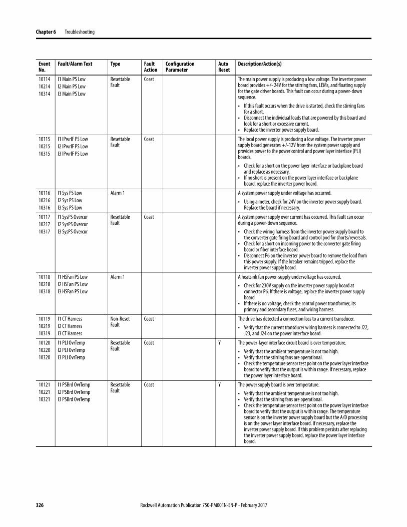
101141021410314
I1 Main PS LowI2 Main PS LowI3 Main PS Low
Resettable Fault
Coast The main power supply is producing a low voltage. The inverter power board provides +/- 24V for the stirring fans, LEMs, and floating supply for the gate driver boards. This fault can occur during a power-down sequence.• If this fault occurs when the drive is started, check the stirring fans
for a short.• Disconnect the individual loads that are powered by this board and
look for a short or excessive current.• Replace the inverter power supply board.
101151021510315
I1 IPwrIF PS LowI2 IPwrIF PS LowI3 IPwrIF PS Low
Resettable Fault
Coast The local power supply is producing a low voltage. The inverter power supply board generates +/-12V from the system power supply and provides power to the power control and power layer interface (PLI) boards.• Check for a short on the power layer interface or backplane board
and replace as necessary.• If no short is present on the power layer interface or backplane
board, replace the inverter power board.
101161021610316
I1 Sys PS LowI2 Sys PS LowI3 Sys PS Low
Alarm 1 A system power supply under voltage has occurred.• Using a meter, check for 24V on the inverter power supply board.
Replace the board if necessary.
101171021710317
I1 SysPS OvercurI2 SysPS OvercurI3 SysPS Overcur
Resettable Fault
Coast A system power supply over current has occurred. This fault can occur during a power-down sequence.• Check the wiring harness from the inverter power supply board to
the converter gate firing board and control pod for shorts/reversals.• Check for a short on incoming power to the converter gate firing
board or fiber interface board.• Disconnect P6 on the inverter power board to remove the load from
this power supply. If the breaker remains tripped, replace the inverter power supply board.
101181021810318
I1 HSFan PS LowI2 HSFan PS LowI3 HSFan PS Low
Alarm 1 A heatsink fan power-supply undervoltage has occurred.• Check for 230V supply on the inverter power supply board at
connector P6. If there is voltage, replace the inverter power supply board.
• If there is no voltage, check the control power transformer, its primary and secondary fuses, and wiring harness.
101191021910319
I1 CT HarnessI2 CT HarnessI3 CT Harness
Non-Reset Fault
Coast The drive has detected a connection loss to a current transducer.• Verify that the current transducer wiring harness is connected to J22,
J23, and J24 on the power interface board.
101201022010320
I1 PLI OvrTempI2 PLI OvrTempI3 PLI OvrTemp
Resettable Fault
Coast Y The power-layer interface circuit board is over temperature.• Verify that the ambient temperature is not too high.• Verify that the stirring fans are operational.• Check the temperature sensor test point on the power layer interface
board to verify that the output is within range. If necessary, replace the power layer interface board.
101211022110321
I1 PSBrd OvrTempI2 PSBrd OvrTempI3 PSBrd OvrTemp
Resettable Fault
Coast Y The power supply board is over temperature.• Verify that the ambient temperature is not too high.• Verify that the stirring fans are operational.• Check the temperature sensor test point on the power layer interface
board to verify that the output is within range. The temperature sensor is on the inverter power supply board but the A/D processing is on the power layer interface board. If necessary, replace the inverter power supply board. If this problem persists after replacing the inverter power supply board, replace the power layer interface board.
Event No.
Fault/Alarm Text Type Fault Action
Configuration Parameter
Auto Reset
Description/Action(s)
326 Rockwell Automation Publication 750-PM001N-EN-P - February 2017

Troubleshooting Chapter 6
101221022210322
I1 InFan1 SlowI2 InFan1 SlowI3 InFan1 Slow
Alarm 1 / Resettable Fault
Stirring fan 1 is under speed.• Visually verify that fan 1 is turning.• Check the measured fan speed displayed in [In InFan n Speed] (port
10).• Check the wiring harness to the stirring fans to verify that the power
and tachometer signals are connected.• If necessary, replace both stirring fans. When the fans are replaced,
the elapsed hours, displayed in [In PredMainReset] (port 10) must be reset.
101231022310323
I1 InFan2 SlowI2 InFan2 SlowI3 InFan2 Slow
101241022410324
I1 NTC OpenI2 NTC OpenI3 NTC Open
Non-Reset Fault
Coast An NTC open condition has occurred.• Check the ribbon cable that runs between the backplane board and
gate driver board for loose connections or damage. The capacitor bank must be removed to check this cable.
• If the drive is located in cold conditions, raise the ambient temperature.
• Check the power-layer interface board testpoints for the individual phase NTC temperatures to determine which is open.
• Reseat the power layer interface board. If this problem persists, replace the power layer interface board.
101251022510325
I1 Incompat UBrdI2 Incompat UBrdI3 Incompat UBrd
Non-Reset Fault
Coast The power layer interface and power control board do not detect the correct gate driver board on the U, V, or W phase. This fault can occur during a power-down sequence.• Check the ribbon cable that runs between the backplane board and
gate driver board for loose connections or damage and verify that the correct gate driver board is installed. The capacitor bank must be removed to check this cable and the board.
• Reflash the control board.• Check the rating plug.
101261022610326
I1 Incompat VBrdI2 Incompat VBrdI3 Incompat VBrd
101271022710327
I1 Incompat WBrdI2 Incompat WBrdI3 Incompat WBrd
101281022810328
I1 Incompat BrdnI2 Incompat BrdnI3 Incompat Brdn
Non-Reset Fault
Coast The drive detected an incompatible burden resistor.• Verify that the correct rating plug is installed. Reseat the rating plug.
101291022910329
I1 DC Bus ImbalI2 DC Bus ImbalI3 DC Bus Imbal
Resettable Fault
Coast Either the lower or upper leg of the capacitor bank is getting too much voltage (based on the bus voltage, measured voltage across the lower leg, and a calculation to find the voltage across the upper leg) or the voltage sensing components are damaged.• Check the value of the bus bleeder resistor and bus balancing resistor
and replace as necessary.• Inspect the capacitor bank for leakage or damage and replace as
necessary. Replacing the capacitor bank assembly also replaces the bus balancing resistor.
• Measure the voltage on each half of the bus to confirm the calculations. If the bus measurements aren’t correct, replace the power interface board and/or inverter power supply board.
101301023010330
I1 Curr OffsetI2 Curr OffsetI3 Curr Offset
Alarm 1 The calculated current offset for any phase is larger than expected.• Check the current sensor offset reading inverter testpoint and power
supply. If necessary, replace the current sensor.• If this problem persists, replace the inverter power supply board and/
or the power layer interface board.
Event No.
Fault/Alarm Text Type Fault Action
Configuration Parameter
Auto Reset
Description/Action(s)
ATTENTION: The DC bus voltage can only be measured when the drive is energized. Servicing energized equipment can be hazardous. Severe injury or death can result from electrical shock, burn, or unintended actuation of controlled equipment. Follow Safety related practices of NFPA 70E, ELECTRICAL SAFETY FOR EMPLOYEE WORKPLACES. DO NOT work alone on energized equipment!
Rockwell Automation Publication 750-PM001N-EN-P - February 2017 327

Chapter 6 Troubleshooting
101311023110331
I1 Fault Q FullI2 Fault Q FullI3 Fault Q Full
Resettable Fault
Coast The fault queue is full. There are at least three other faults in the queue. Troubleshooting and clearing the existing faults makes room for additional faults in the queue (if any).This fault can occur during a power-down sequence.
101321023210332
I1 Incompat PSI2 Incompat PSI3 Incompat PS
Resettable Fault
Coast The drive has detected an incompatible power supply for the drive AC input rating.• Check the power supply and replace it if incorrect.• If the power supply is correct, reflash the control board.• If this problem persists, replace the inverter power supply board or
power layer interface board.
101341023410334
I1 UBrd FaultI2 UBrd FaultI3 UBrd Fault
Resettable Fault
Coast The power supply on the U, V, or W phase gate driver board has failed.• If this fault occurred on this phase only, replace the appropriate gate
driver board.• If this fault occurred on all three phases, check the 24V power supply
on the inverter power supply board that feeds the gate driver boards and replace the inverter power supply board if necessary.
101351023510335
I1 VBrd FaultI2 VBrd FaultI3 VBrd Fault
101361023610336
I1 WBrd FaultI2 WBrd FaultI3 WBrd Fault
101371023710337
I1 Flash FailedI2 Flash FailedI3 Flash Failed
Resettable Fault
Coast This fault will be asserted if an attempt to flash the FPGA configuration device fails.
101381023810338
I1 Powering DownI2 Powering DownI3 Powering Down
Resettable Fault
Coast This fault will be asserted at 80% of the rated DC bus voltage.
Event No.
Fault/Alarm Text Type Fault Action
Configuration Parameter
Auto Reset
Description/Action(s)
328 Rockwell Automation Publication 750-PM001N-EN-P - February 2017

Troubleshooting Chapter 6
Converter (Port 11) Faults and Alarms (Frame 8 and Larger)
Table 13 contains a list of Converter-specific faults and alarms, the type of fault or alarm, the action that is taken when the drive faults, the parameter that is used to configure the fault or alarm (if applicable), and a description and action (where applicable). These faults and alarms only apply to Frame 8 drives and larger.
Table 13 - Converter Fault and Alarm Types, Descriptions, and Actions
Event No.
Fault/Alarm Text Type Fault Action
Configuration Parameter
Auto Reset
Description/Action(s)
111011120111301
C1 PrechargeC2 PrechargeC3 Precharge
Alarm 1 1. The AC line voltage is in the range of 50...300V (for 400V class drives) or 50...400V (for 600V class drives). Precharge begins when the AC line voltage reaches 300V or 400V.
2. The drive has been in precharge for more than 12 seconds. If the “Cn Precharge” alarm persists for more than 30 seconds the drive will fault. Following powerup or a fault reset, the converter does not issue any voltage-related alarms until the AC input voltage exceeds 50V to prevent an alarm when a customer-supplied auxiliary power supply is used.
3. The DC bus open circuit test can be cycling. If this test cycles for more than 10 seconds, event 144/244 “Cn DC Bus Open” occurs.
Alarm:• Check the line voltage displayed in [Cn L12 Line Volt], [Cn L23 Line
Volt], and [CV L31 Line Volt] (port 11).• Check the phase current displayed in [Cn L1 Phase Curr], [Cn L2 Phase
Curr], and [Cn L3 Phase Curr] (port 11) and the bus voltage in [Cn DC Bus Volt] (port 11). Line current, line voltage, and bus voltage sensing are all performed on the converter gate firing board. If this alarm persists, replace the converter gate firing board.
Fault:• Verify that the current transducers have not all failed. If necessary,
replace all three current transducers.• Verify that the DC link inductor has not failed. If necessary, replace
the DC link choke.• Verify that the converter line and DC bus wiring is connected.• Verify that the capacitor bank is properly installed and connected.
Non-Reset Fault
Coast
111021120211302
C1 Phase Loss L1C2 Phase Loss L1C3 Phase Loss L1
Alarm 1 The AC line-to-line voltages are imbalanced, indicating an open AC input phase.• Check for an upstream AC line loss.• Verify that the AC input line wiring is properly connected.• Check the wiring harness to the converter gate firing board for loose
connections and/or damage. If necessary, replace the converter gate-firing board wiring harness.
111031120311303
C1 Phase Loss L2C2 Phase Loss L2C3 Phase Loss L2
111041120411304
C1 Phase Loss L3C2 Phase Loss L3C3 Phase Loss L3
111111121111311
C1 SCR OvrTempC2 SCR OvrTempC3 SCR OvrTemp
Alarm 1 Y An alarm occurs if the calculated SCR temperature exceeds 125 °C (257 °F) and a fault occurs when the calculated SCR temperature exceeds 135 °C (275 °F).• Check for cooling problems - the heatsink cooling fan is running
slow, the enclosure filter or heatsink fins are dirty, or the ambient temperature is too high.
Resettable Fault
Coast
111121121211312
C1 HS OvrTempC2 HS OvrTempC3 HS OvrTemp
Alarm 1 Y An alarm when the heatsink temperature exceeds 95 °C (203 °F) and a fault when the heatsink temperature exceeds 100 °C (212 °F).• Check the NTC for a short or verify that it is connected.• Measure the resistance of the NTC. The reading should be
approximately 11.5 Ω, at room temperature.• Check for cooling problems - the heatsink cooling fan is running
slow, the enclosure filter or heatsink fins are dirty, or the ambient temperature is too high.
Resettable Fault
Coast
Rockwell Automation Publication 750-PM001N-EN-P - February 2017 329

Chapter 6 Troubleshooting
111131121311313
C1 TVSS BlownC2 TVSS BlownC3 TVSS Blown
Alarm 1 The MOV block is reporting that the transient voltage suppression system (TVSS) has blown.• Check the MOV wiring harness for loose connections and/or damage
and replace if necessary.• Replace the MOV block.• If the MOV block is not blown and the wiring harness is properly
connected and not damaged, replace the converter gate firing board.
111141121411314
C1 Blower SpeedC2 Blower SpeedC3 Blower Speed
Alarm 1 The converter cooling fan is running below normal operating speed.• Check for debris in the fan. If necessary, clean the fan and housing.• Check for noise at the fan, indicating motor bearing failure.• Verify that the fan power and feedback connections are not loose or
disconnected.• Replace the fan, if necessary.
111151121511315
C1 Line DipC2 Line DipC3 Line Dip
Alarm 1 Y The bus voltage has fallen below the value specified in P451 [Pwr Loss A Level] or P454 [Pwr Loss B Level] (port 0) minus 20 volts. Until the converter has established communications with the main control board, this value defaults to 180V below the converter bus memory. The converter stops firing the SCRs until the nominal value of the DC bus voltage for the present AC line voltage is within 60 volts of P12 [DC Bus Memory] (port 0). If the line dip condition persists for more than 60 seconds the alarm becomes a fault.• Verify the power wiring connections.• Compare the actual DC bus voltage to the value displayed in [Cn DC
Bus Volt]. If the values are different, replace the converter gate firing board.
Resettable Fault
Coast
111161121611316
C1 Minimum LineC2 Minimum LineC3 Minimum Line
Alarm 1 The AC line voltage is less than 280V (for a 400V class drive) / 400V (for a 600V class drive).• The AC line voltage must exceed 320V / 440V to recover from this
alarm.
111171121711317
C1 Line FreqC2 Line FreqC3 Line Freq
Alarm 1 The measured line frequency is out of the range (below 40 Hz, or above 65 Hz). This alarm becomes a fault if the condition persists for more than 30 seconds.• Check the incoming power line frequency.• Check the wiring harness to the converter gate firing board for loose
connections and/or damage and replace if necessary.• If the wiring harness is properly connected and not damaged,
replace the converter gate firing board.
Resettable Fault
Coast
111181121811318
C1 Single PhaseC2 Single PhaseC3 Single Phase
Alarm 1 The converter was intentionally powered up in single-phase mode with only AC phase L1-L2 present. Intentional single-phase mode is only detected at the initial application of AC line voltage. Application of 3-phase voltage after the converter has entered single-phase mode results in the single phase alarm becoming a fault.• Verify that only one phase is applied to a drive in single-phase mode.
Resettable Fault
Coast
111341123411334
C1 OvercurrentC2 OvercurrentC3 Overcurrent
Resettable Fault
Coast The peak AC input current has exceeded 3000 A for five line cycles.• Verify that the current transducers are connected.• Check the wiring harness to the converter gate firing board for loose
connections or damage and replace if necessary.• If the current transducers are properly connect and the wiring
harness for the gate firing board is OK, replace the converter gate firing board.
• Check for an open SCR or DC bus short.
Event No.
Fault/Alarm Text Type Fault Action
Configuration Parameter
Auto Reset
Description/Action(s)
330 Rockwell Automation Publication 750-PM001N-EN-P - February 2017

Troubleshooting Chapter 6
111351123511335
C1 Ground FaultC2 Ground FaultC3 Ground Fault
Resettable Fault
Coast Y The converter input ground current (peak) has exceeded the threshold set P16 [Gnd Cur Flt Lvl] (port 11) for 5 line cycles. A possible internal short in the drive between a phase, ground, or the DC bus can have occurred.• Verify that the current transducer wiring harness is connected to the
converter gate firing board and that they are functioning properly. If necessary, replace all three current transducers (CTs).
• If the current transducer wiring harness is connected and the CTs are functioning properly, replace the converter gate firing board.
• To determine if there is an imbalance between the phases, view the input phase current values in [Cn L1 Phase Curr], [Cn L2 Phase Curr], and [Cn L3 Phase Curr] (port 11). [Cn Gnd Current] (port 11) is the calculated (not measured) ground current based on the phase currents. If necessary, use trending when the ground fault occurs upon drive power-up.
111361123611336
C1 HS NTC OpenC2 HS NTC OpenC3 HS NTC Open
Non-Reset Fault
Coast The converter heatsink NTC is open. The heatsink NTC is mounted on the converter heatsink and is wired to the converter gate firing board. An open NTC is assumed when the heatsink temperature is below -40 °C(-40 °F).• Check for loose connections or damage to the NTC wiring harness.• Measure the resistance of the NTC and verify that it is within range.• If the NTC wiring harness and resistance measurement is OK, replace
the converter gate firing board.
111371123711337
C1 HS NTC ShortC2 HS NTC ShortC3 HS NTC Short
Non-Reset Fault
Coast The converter heatsink NTC is shorted. The heatsink NTC is mounted on the converter heatsink and is wired to the converter gate firing board. A shorted NTC is assumed when the heatsink temperature is above 200 °C (392 °F).• Check for loose connections or damage to the NTC wiring harness.• Measure the resistance of the NTC and verify that it is within range.• If the NTC wiring harness and resistance measurement is OK, replace
the converter gate firing board.
111381123811338
C1 Brd OvrTempC2 Brd OvrTempC3 Brd OvrTemp
Resettable Fault
Coast Y The gate firing board is over temperature. This fault occurs when the gate firing board temperature exceeds 70 °C (158 °F).• Check the cabinet fan wiring harness for loose connections or
damage and that the fan is running. If necessary, replace the fan wiring harness and/or fan.
• Lower the ambient temperature.• Replace the converter gate firing board.
111391123911339
C1 Brd NTC OpenC2 Brd NTC OpenC3 Brd NTC Open
Non-Reset Fault
Coast The converter gate firing board NTC is open. An open NTC is assumed when the temperature is below -40 °C (-40 °F).• Replace the converter gate firing board.
111401124011340
C1 Brd NTC ShortC2 Brd NTC ShortC3 Brd NTC Short
Non-Reset Fault
Coast The converter gate firing board NTC is shorted. A shorted NTC is assumed when the temperature is above 200 °C (392 °F).• Replace the converter gate firing board.
111411124111341
C1 Power SupplyC2 Power SupplyC3 Power Supply
Resettable Fault
Coast A power supply input voltage (24V input and/or +/-12V internal supply) is operating outside of the acceptable range.• Check input power to the converter gate firing board. The following
thresholds are used:24V is below 20.1V12V is below 10.0V12V is above 15.0V-12V is above -10.0V
• If the power supply voltage is within the acceptable range, replace the converter gate firing board.
Event No.
Fault/Alarm Text Type Fault Action
Configuration Parameter
Auto Reset
Description/Action(s)
Rockwell Automation Publication 750-PM001N-EN-P - February 2017 331

Chapter 6 Troubleshooting
111421124211342
C1 Comm LossC2 Comm LossC3 Comm Loss
Resettable Fault
Coast The converter gate firing board lost communications (through the power layer interface board) to the main control board. Once the root cause of the communication fault has been resolved, power must be cycled or a drive reset must be initiated to clear this fault.
• Verify that the fiber optic cables are properly connected to the transceivers.
• Verify that the transceivers are properly seated in the ports.• Verify that the fiber optic cable is not cracked or broken.• Verify that power is applied to the fiber optic interface board, gate
firing board, and power layer interface board. If necessary, replace the fiber optic interface, gate firing board, and/or power layer interface board.
111431124311343
C1 Firmware FltC2 Firmware FltC3 Firmware Flt
Non-Reset Fault
Coast A firmware fault has occurred.• Reset the drive. If this fault persists, replace the converter gate firing
board.
111441124411344
C1 DC Bus OpenC2 DC Bus OpenC3 DC Bus Open
Non-Reset Fault
Coast The DC bus voltage did not rise above 12V (for 400V class drives) or 20V (for 600V class drives) as the SCRs began to ramp on. In this case, the converter tries to turn on the SCRs for approximately 10 seconds before issuing this fault. Event 101/201 “Cn Precharge” is issued following the first retry.• Verify that the current transducers have not all failed. If necessary,
replace all three current transducers.• Verify that the DC link inductor has not failed. If necessary, replace
the DC link choke.• Verify that the converter line and DC bus wiring is connected.• Verify that the capacitor bank is properly installed and connected.
111451124511345
C1 DC Bus ShortC2 DC Bus ShortC3 DC Bus Short
Non-Reset Fault
Coast The peak current has exceeded 150 % of the converter rating during the precharge sequence. Peak charging current is normally limited to 50 % of the converter rating.• Check for a DC bus short, internally and externally.• Verify that the wiring harness to P10 on the converter gate firing
board is connected and not damaged. Replace the harness as necessary.
• Verify that the capacitor bank is properly installed and connected.• Check for an IGBT short and replace as necessary.
111461124611346
C1 CT HarnessC2 CT HarnessC3 CT Harness
Non-Reset Fault
Coast A current transducer (CT) wiring harness connection loss has been detected.• Verify that the CT wiring harness is not damaged and is connected to
P6 on the converter gate firing board. Replace the wiring harness if necessary.
• If this problem persists, replace the converter gate firing board.
111471124711347
C1 LFuse HarnessC2 LFuse HarnessC3 LFuse Harness
Non-Reset Fault
Coast A line-fuse wiring harness connection loss has been detected.• Verify that the line fuse wiring harness is not damaged and is
connected to P7 on the converter gate firing board. Replace the wiring harness if necessary.
• If this problem persists, replace the converter gate firing board.
Event No.
Fault/Alarm Text Type Fault Action
Configuration Parameter
Auto Reset
Description/Action(s)
ATTENTION: Hazard of permanent eye damage exists when using optical transmission equipment. This product emits intense light and invisible radiation. Do not look into fiber-optic ports or fiber-optic cable connectors. Remove power from the drive before disconnecting fiber optic cables.
332 Rockwell Automation Publication 750-PM001N-EN-P - February 2017

Troubleshooting Chapter 6
111481124811348
C1 Line Fuse L1C2 Line Fuse L1C3 Line Fuse L1
Non-Reset Fault
Coast The line fuse for Line n has blown.• Check the fuse and replace if necessary.• Verify that the line fuse wiring harness for line 1 is not damaged and
is connected to P7 on the converter gate firing board. Replace the wiring harness if necessary.
• If this problem persists, replace the converter gate firing board.111491124911349
C1 Line Fuse L2C2 Line Fuse L2C3 Line Fuse L2
111501125011350
C1 Line Fuse L3C2 Line Fuse L3C3 Line Fuse L3
111571125711357
C1 BFuse HarnessC2 BFuse HarnessC3 BFuse Harness
Non-Reset Fault
Coast A bus-fuse wiring harness connection loss has been detected.• Check the bus fuse harness and replace if necessary.• If this problem persists, replace the converter gate firing board.
111581125811358
C1 BFuse PosC2 BFuse PosC3 BFuse Pos
Non-Reset Fault
Coast The DC+ bus fuse is blown.• Check the DC+ bus fuse and wiring harness and replace if necessary.• If this problem persists, replace the converter gate firing board.
111591125911359
C1 BFuse NegC2 BFuse NegC3 BFuse Neg
Non-Reset Fault
Coast The DC- bus fuse is blown.• Check the DC- bus fuse and wiring harness and replace if necessary.• If this problem persists, replace the converter gate firing board.
111601126011360
C1 Command StopC2 Command StopC3 Command Stop
Resettable Fault
Coast Y The main control board has commanded the converter gate firing board to stop due to an asymmetrical bus condition.• Check the DC bus connections and wiring.
111611126111361
C1 AC Line HighC2 AC Line HighC3 AC Line High
Resettable Fault
Coast The AC line voltage has exceeded 565V (for 400V class drives) or 815V (for 600V class drives), which corresponds to the nominal bus voltage of 799V DC (for 400V class drives) or 1150V DC (for 600V class drives). This fault is intended to protect the capacitor bank from an overvoltage condition especially if a 400V class drive is inadvertently placed in a 600V system.• Verify the incoming line voltage.
111621126211362
C1 Line LossC2 Line LossC3 Line Loss
Resettable Fault
Coast Y An AC line loss has occurred.• Monitor the incoming AC line for low voltage or line power
interruption.
111631126311363
C1 Fault Q FullC2 Fault Q FullC3 Fault Q Full
Resettable Fault
Coast The fault queue is full. There are at least three other faults in the queue.• Troubleshooting and clearing the existing faults make room for
additional faults in the queue (if any).
Event No.
Fault/Alarm Text Type Fault Action
Configuration Parameter
Auto Reset
Description/Action(s)
Rockwell Automation Publication 750-PM001N-EN-P - February 2017 333

Chapter 6 Troubleshooting
Precharge (Port 11) Faults and Alarms (Frame 8 and Larger)
Table 14 contains a list of Precharge-specific faults and alarms, the type of fault or alarm, the action that is taken when the drive faults, the parameter that is used to configure the fault or alarm (if applicable), and a description and action (where applicable). These faults and alarms only apply to Frame 8 drives and larger.
Table 14 - Converter Fault and Alarm Types, Descriptions, and Actions
Event No.
Fault/Alarm Text Type Fault Action
Configuration Parameter
Auto Reset
Description/Action(s)
111011120111301
P1 PrechargeP2 PrechargeP3 Precharge
Alarm 1 The DC bus delta voltage (Vbus_in - Vbus_out) is greater than 25V when the molded case switch (MCS) is open. This alarm is suppressed when the Precharge Fault is present.
Resettable Fault
Coast The DC bus voltage did not meet the conditions that are required to close the molded case switch (MCS) within the timeout period.1. DC bus input is not overvoltage2. DC bus input is not undervoltage3. DC bus delta voltage (Vbus_in - Vbus_out) is less than 25V
111151121511315
P1 Bus DipP2 Bus DipP3 Bus Dip
Alarm 1 Only occurs when the drive is offline or in stand-alone mode. The bus voltage has dipped more than 180V below the drive bus memory. The alarm is released when the bus voltage rises back to within 60V of the drive bus memory.
111191121911319
P1 240 V AC LossP2 240 V AC LossP3 240 V AC Loss
Alarm 1 240V AC not present while the drive is in the inactive state. This alarm is suppressed when the 240V AC Loss Fault is present.
Resettable Fault
Coast 240V AC was lost while in the active state. Active state whenever the drive is not stopped, for example, the molded case switch (MCS) is opening or closing or is closed.
111201122011320
P1 240V AC DisconP2 240V AC DisconP3 240V AC Discon
Alarm 1 The 240V AC disconnect is open when the precharge controller is in the ready state (MCS is not closed).
111211122111321
P1 Bus UndervoltP2 Bus UndervoltP3 Bus Undervolt
Alarm 1 The input bus voltage is below 400V DC while the molded case switch (MCS) is open. Hysteresis level 420V DC. This alarm is suppressed when the Bus Undervoltage Fault is present.
Resettable Fault
Coast The bus input voltage fell below 400V while the molded case switch (MCS) was closed. Hysteresis level at 420V. The system SMPS cuts out near 340V DC.
111221122211322
P1 Bus OvervoltP2 Bus OvervoltP3 Bus Overvolt
Alarm 1 The input bus voltage exceeds 820V DC. Hysteresis level 800V DC.
111231122311323
P1 Door OpenP2 Door OpenP3 Door Open
Alarm 1 Door closure contact is open.
111301123011330
P1 MCS ShuntTripP2 MCS ShuntTripP3 MCS ShuntTrip
Resettable Fault
Coast The molded case switch (MCS) auxiliary contact did not open within 1 second following the shunt trip coil activation.
111311123111331
P1 MCS CloseFailP2 MCS CloseFailP3 MCS CloseFail
Resettable Fault
Coast The molded case switch (MCS) auxiliary contact did not close within 2 seconds following the close coil activation.
111321123211332
P1 MCSAuxContactP2 MCSAuxContactP3 MCSAuxContact
Resettable Fault
Coast The molded case switch (MCS) auxiliary contact was open when the MCS was closed or closed when the MCS was open. If the MCS Failed to Close Fault is present, then this fault is not reported.
111331123311333
P1 MCS ClosedP2 MCS ClosedP3 MCS Closed
Resettable Fault
Coast The voltage across the molded case switch (MCS) when it was closed exceeded 10V.
334 Rockwell Automation Publication 750-PM001N-EN-P - February 2017

Troubleshooting Chapter 6
111381123811338
P1 Brd OvertempP2 Brd OvertempP3 Brd Overtemp
Resettable Fault
Coast Y The gate firing board is over temperature. This fault occurs when the gate firing board temperature exceeds 70 °C (158 °F).• Check the cabinet fan wiring harness for loose connections or
damage and that the fan is running. If necessary, replace the fan wiring harness and/or fan.
• Lower the ambient temperature.• Replace the converter gate firing board.
111391123911339
P1 Brd NTC OpenP2 Brd NTC OpenP3 Brd NTC Open
Non-Reset Fault
Coast The converter gate firing board NTC is open. An open NTC is assumed when the temperature is below -40 °C (-40 °F).• Replace the converter gate firing board.
111401124011340
P1 Brd NTC ShortP2 Brd NTC ShortP3 Brd NTC Short
Non-Reset Fault
Coast The converter gate firing board NTC is shorted. A shorted NTC is assumed when the temperature is above 200 °C (392 °F).• Replace the converter gate firing board.
111411124111341
P1 Power SupplyP2 Power SupplyP3 Power Supply
Resettable Fault
Coast A power supply input voltage (24V input and/or +/-12V internal supply) is operating outside of the acceptable range.• Check input power to the converter gate firing board. The following
thresholds are used:24V is below 20.1V12V is below 10.0V12V is above 15.0V-12V is above -10.0V
• If the power supply voltage is within the acceptable range, replace the converter gate firing board.
111421124211342
P1 Comm LossP2 Comm LossP3 Comm Loss
Resettable Fault
Coast The converter gate firing board lost communications (through the power layer interface board) to the main control board. Once the root cause of the communication fault has been resolved, power must be cycled or a drive reset must be initiated to clear this fault.
• Verify that the fiber optic cables are properly connected to the transceivers.
• Verify that the transceivers are properly seated in the ports.• Verify that the fiber optic cable is not cracked or broken.• Verify that power is applied to the fiber optic interface board, gate
firing board, and power layer interface board. If necessary, replace the fiber optic interface, gate firing board, and/or power layer interface board.
111431124311343
P1 Firmware FltP2 Firmware FltP3 Firmware Flt
Non-Reset Fault
Coast A firmware fault has occurred.• Reset the drive. If this fault persists, replace the converter gate firing
board.
111451124511345
P1 DC Bus ShortP2 DC Bus ShortP3 DC Bus Short
Non-Reset Fault
Coast The peak current has exceeded 150 % of the converter rating during the precharge sequence. Peak charging current is normally limited to 50 % of the converter rating.• Check for a DC bus short, internally and externally.• Verify that the wiring harness to P10 on the converter gate firing
board is connected and not damaged. Replace the harness as necessary.
• Verify that the capacitor bank is properly installed and connected.• Check for an IGBT short and replace as necessary.
111571125711357
P1 BFuse HarnessP2 BFuse HarnessP3 BFuse Harness
Non-Reset Fault
Coast A bus-fuse wiring harness connection loss has been detected.• Check the bus fuse harness and replace if necessary.• If this problem persists, replace the converter gate firing board.
Event No.
Fault/Alarm Text Type Fault Action
Configuration Parameter
Auto Reset
Description/Action(s)
ATTENTION: Hazard of permanent eye damage exists when using optical transmission equipment. This product emits intense light and invisible radiation. Do not look into fiber-optic ports or fiber-optic cable connectors. Remove power from the drive before disconnecting fiber-optic cables.
Rockwell Automation Publication 750-PM001N-EN-P - February 2017 335

Chapter 6 Troubleshooting
111581125811358
P1 BFuse PosP2 BFuse PosP3 BFuse Pos
Non-Reset Fault
Coast The DC+ bus fuse is blown.• Check the DC+ bus fuse and wiring harness and replace if necessary.• If this problem persists, replace the converter gate firing board.
111591125911359
P1 BFuse NegP2 BFuse NegP3 BFuse Neg
Non-Reset Fault
Coast The DC- bus fuse is blown.• Check the DC- bus fuse and wiring harness and replace if necessary.• If this problem persists, replace the converter gate firing board.
111601126011360
P1 Command StopP2 Command StopP3 Command Stop
Resettable Fault
Coast Y The main control board has commanded the converter gate firing board to stop due to an asymmetrical bus condition.• Check the DC bus connections and wiring.
111631126311363
P1 Fault Q FullP2 Fault Q FullP3 Fault Q Full
Resettable Fault
Coast The fault queue is full. There are at least three other faults in the queue.• Troubleshooting and clearing the existing faults make room for
additional faults in the queue (if any).
Event No.
Fault/Alarm Text Type Fault Action
Configuration Parameter
Auto Reset
Description/Action(s)
336 Rockwell Automation Publication 750-PM001N-EN-P - February 2017